EP4044404A1 - Stator de moteur à refroidissement axial à enroulement concentré et moteur - Google Patents
Stator de moteur à refroidissement axial à enroulement concentré et moteur Download PDFInfo
- Publication number
- EP4044404A1 EP4044404A1 EP21821636.4A EP21821636A EP4044404A1 EP 4044404 A1 EP4044404 A1 EP 4044404A1 EP 21821636 A EP21821636 A EP 21821636A EP 4044404 A1 EP4044404 A1 EP 4044404A1
- Authority
- EP
- European Patent Office
- Prior art keywords
- stator
- cooling medium
- axial
- stator winding
- winding
- Prior art date
- Legal status (The legal status is an assumption and is not a legal conclusion. Google has not performed a legal analysis and makes no representation as to the accuracy of the status listed.)
- Granted
Links
Images



Classifications
-
- H—ELECTRICITY
- H02—GENERATION; CONVERSION OR DISTRIBUTION OF ELECTRIC POWER
- H02K—DYNAMO-ELECTRIC MACHINES
- H02K3/00—Details of windings
- H02K3/04—Windings characterised by the conductor shape, form or construction, e.g. with bar conductors
- H02K3/24—Windings characterised by the conductor shape, form or construction, e.g. with bar conductors with channels or ducts for cooling medium between the conductors
-
- H—ELECTRICITY
- H02—GENERATION; CONVERSION OR DISTRIBUTION OF ELECTRIC POWER
- H02K—DYNAMO-ELECTRIC MACHINES
- H02K1/00—Details of the magnetic circuit
- H02K1/06—Details of the magnetic circuit characterised by the shape, form or construction
- H02K1/12—Stationary parts of the magnetic circuit
- H02K1/20—Stationary parts of the magnetic circuit with channels or ducts for flow of cooling medium
-
- H—ELECTRICITY
- H02—GENERATION; CONVERSION OR DISTRIBUTION OF ELECTRIC POWER
- H02K—DYNAMO-ELECTRIC MACHINES
- H02K1/00—Details of the magnetic circuit
- H02K1/06—Details of the magnetic circuit characterised by the shape, form or construction
- H02K1/12—Stationary parts of the magnetic circuit
- H02K1/14—Stator cores with salient poles
- H02K1/146—Stator cores with salient poles consisting of a generally annular yoke with salient poles
-
- H—ELECTRICITY
- H02—GENERATION; CONVERSION OR DISTRIBUTION OF ELECTRIC POWER
- H02K—DYNAMO-ELECTRIC MACHINES
- H02K3/00—Details of windings
- H02K3/46—Fastening of windings on the stator or rotor structure
- H02K3/52—Fastening salient pole windings or connections thereto
- H02K3/521—Fastening salient pole windings or connections thereto applicable to stators only
- H02K3/522—Fastening salient pole windings or connections thereto applicable to stators only for generally annular cores with salient poles
-
- H—ELECTRICITY
- H02—GENERATION; CONVERSION OR DISTRIBUTION OF ELECTRIC POWER
- H02K—DYNAMO-ELECTRIC MACHINES
- H02K9/00—Arrangements for cooling or ventilating
- H02K9/19—Arrangements for cooling or ventilating for machines with closed casing and closed-circuit cooling using a liquid cooling medium, e.g. oil
Definitions
- the present invention claims the priority of a Chinese patent application No. 202010518076.9 filed with the China National Intellectual Property Administration (CNIPA) on June 9, 2020 , entitled "a concentrated winding axial cooling motor stator and a motor”.
- CNIPA China National Intellectual Property Administration
- the present invention belongs to the technical field of motors, in particular relates to a concentrated winding axial cooling motor stator and a motor.
- stator coils a rotating magnetic field is generated when an AC/BC passes through the coils, and interacts with a magnetic field of a rotor to generate an electromagnetic torque, so that the motor rotates.
- a current when passing through stator coils has energy loss under the effect of a resistance, and the lost energy is mainly transformed into heat. Therefore, how to well control temperature rise of the stator coils becomes very important.
- oil cooled motors of the same kind mainly depend on oil cooling at an end part of a stator and a middle part of a stator core and oil shredding of the rotor towards end parts of two sides of the stator to achieve heat dissipation.
- the present invention provides a concentrated winding axial cooling motor stator and a motor so as to resolve the above-mentioned or other previous problems in a prior art.
- a concentrated winding axial cooling motor stator is arranged on a casing, includes a stator core and stator windings arranged on the stator core, and further includes barriers and an axial oil feeding device, wherein,
- each barrier and coils of two adjacent groups of the stator windings in slots of the stator core constitute a cooling medium communication cavity
- the spray hole corresponds to the cooling medium communication cavity
- the barrier blocks off a cooling medium flowing out of the spray hole and guides a flow line of the cooling medium, so that the cooling medium flows along the axial inner surface of the stator winding in the two adjacent groups of the stator windings towards two ends of the stator winding.
- an axis of the spray hole extends slantly from the spray hole towards an end away from the stator winding and provided with the axial oil feeding device.
- a plurality of spray holes are provided, and each cooling medium communication cavity corresponds to a location of at least one of the spray holes;
- the axial oil feeding device further includes:
- a cross section of the oil pipe body is in a shape of a circle or a polygon.
- the oil pipe body is of an annular structure, or a plurality of oil pipe bodies are provided, and the plurality of oil pipe bodies are annularly arranged by taking the axis of the stator winding as a center.
- the barrier has a flow guide portion, and the flow guide portion is opposite to the corresponding spray hole for changing a flow direction of the cooling medium.
- the barrier is a slot wedge, a frame or insulating paper.
- a concentrated winding motor includes a concentrated winding axial cooling motor stator as mentioned above.
- the concentrated winding axial cooling motor stator is simple in structure and convenient to use.
- the concentrated winding axial cooling motor stator has an axial oil feeding device that is arranged on a leading-out terminal or a non-leading-out terminal of a motor stator, spraying of a cooling medium is carried out on an end of the motor stator, an axis of a spray hole of an axial cooling structure and an axis of a stator winding are intersected obliquely, so that a cooling medium outflow line is slant and a cooling medium is sprayed towards the other end of the motor stator onto the barrier and blocked off by the barrier.
- the barrier has a flow guide portion for shunting the cooling medium and changing a flow direction of the cooling medium, so that the cooling medium is divided into two portions and sprayed to an axial inner surface of coils of the concentrated winding stator, flows along the axial inner surface of the coils towards two ends of the stator winding and flows out from the two ends, thereby increasing a heat exchange contact area between the cooling medium and the winding, improving heat dissipation capability, solving the problem that the middle part of the coils of the concentrated winding is quick to temperature rise and a temperature difference between two end parts is large as the cooling medium flows through the whole axial inner surface of the coils, and promoting power density.
- the inclination angles of axes of the spray holes are different, so amounts of the cooling medium flowing to two ends are different. Due to different oil outflow angles, allocation of amounts of the cooling medium axially flowing to two end parts is adjusted, so that the axial oil feeding device is able to cool different types of stator windings, and thus has a wide application range.
- the axial oil feeding device has an oil pipe body with a cavity provided therein, and one side of the oil pipe body facing the stator winding is provided with a plurality of spray holes.
- the oil pipe body encircles the circumferential side of the stator winding and is mounted in a yoke space at any end of the motor stator, therefore, the yoke of the stator is fully used, and as the yoke and the stator are secured on a casing, space utilization rate is improved; or the axial oil feeding device is mounted on the casing or integrated on the casing, the axial oil feeding device corresponds to the location of the yoke of the stator when the motor stator is mounted, an interior space of the casing is fully used, and space utilization rate of the casing is improved.
- gearbox lubricating oil as a cooling medium, the lubricating oil flows out of a gearbox into the axial oil feeding device to cool the motor stator, therefore, the gearbox body is simple in oil line design, small in required space, and easy to realize.
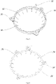
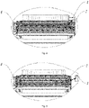
- Fig.1 shows a structure of an embodiment of the present invention, particularly shows the structure and a connection relationship of the present embodiment.
- the present embodiment relates to a concentrated winding axial cooling motor stator and a motor for new energy vehicles.
- an axial oil feeding device By arrangement of an axial oil feeding device, axial cooling of the concentrated winding axial cooling motor stator is carried out, a cooling medium is directly sprayed on an axial inner surface of coils of the concentrated winding stator, flows along the inner surface of the coils of the stator towards two ends of the stator winding and flows out from the two ends, thereby increasing a heat exchange contact area between the cooling medium and the winding, improving heat dissipation capability, solving a problem that a middle part of the coils of the concentrated winding is quick to temperature rise and a temperature difference between two end parts is large, and promoting power density; meanwhile, the axial oil feeding device is arranged on a yoke at any end of a stator core or mounted on a casing,
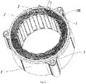
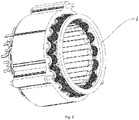
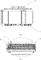
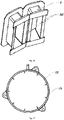
- a concentrated winding axial cooling motor stator as shown in Figs.3 to 6 , is arranged on a casing.
- the casing may be a hybrid box body, a single motor casing, or other box bodies, which can be set in accordance with actual requirements.
- the concentrated winding axial cooling motor stator includes a stator core 4 and stator windings 2, the stator windings 2 are arranged on the stator core 4 to form electromagnetic circuits and generate rotating magnetic fields, and the stator windings 2 use a concentrated wiring mode.
- the concentrated winding axial cooling motor stator further includes an axial oil feeding device 1 and barriers, wherein, the barriers are arranged on the stator core 4, are in contact with the stator windings 2, fix the stator windings 2 and plug notches of the stator core 4.
- Each barrier and stator winding coils at two sides in slots of the stator core 4 constitute a cooling medium communication cavity for flowing of the cooling medium that flows out of the axial oil feeding device 1 and facilitating the cooling medium to be sprayed on the axial inner surface of the stator winding coils.
- the cooling medium communication cavity is a space formed by the barrier and slot portions of the stator winding coils at two lateral walls of the slots of the stator core for facilitating flowing of the cooling medium.
- the barrier is a slot wedge 3, a frame 8 or insulating paper.
- the slot wedge 3 is arranged at a notch of the stator core 4, is in contact with the stator winding 2, and fixes the stator winding 2 to prevent the stator winding 2 from departing from the slot of the stator core 4.
- the frame 8 is arranged at teeth of the stator core 4, sleeves on the stator core 4, is in contact with the stator winding 2, and fixes the stator winding 2 to prevent the stator winding 2 from departing from the slot of the stator core 4.
- the barrier When the barrier is insulating paper, the insulating paper is arranged on an inner wall of the slot of the stator core 4, blocks off the notch of the slot of the stator core 4, and is in contact with the stator winding 2 to prevent the stator winding 2 from departing from the slot of the stator core 4.
- the barrier may be in other structures, which can be selected in accordance with actual requirements and thus is not particularly limited hereby.
- the axial oil feeding device 1 is arranged at any end part of the stator core 4 or is connected with a casing, and a location of the axial oil feeding device 1 corresponds to any end of the stator core 4.
- One side of the axial oil feeding device 1 close to the stator winding 2 is provided with a spray hole 102.
- the spray hole 102 corresponds to a cooling medium communication cavity.
- the barrier blocks off a cooling medium flowing out of the spray hole 102 and guides a flow line of the cooling medium, so that the cooling medium flows along the axial inner surface of the stator winding 2 towards two ends of the stator winding 2.
- the cooling medium flowing out of the axial oil feeding device 1 flows in the cooling medium communication cavity, is sprayed on the barrier and/or coils of the stator winding 2, the cooling medium sprayed on the coils of the stator winding 2 flows along the axial inner surface of the coils of the stator winding, while the cooling medium sprayed on the barrier is blocked off by the barrier and changed in the flow line direction.
- the cooling medium is divided into two portions both of which flow along the axial inner surface of the coils of the stator winding respectively, one portion of the cooling medium flows towards one end of the stator winding 2, and the other portion of the cooling medium flows towards the other end of the stator winding 2, so that the cooling medium flows through the whole axial inner surface of the stator winding 2, and the cooling medium is in full contact with the whole coils of the stator winding, thereby increasing a heat exchange contact area, and improving heat dissipation capability.
- the axial oil feeding device 1 is arranged at any end part of the stator core 4, as shown in Figs.3 to 5 , i.e., the axial oil feeding device 1 is connected with the stator core 4 and arranged on a leading-out terminal 6 of the stator winding 2, or the axial oil feeding device 1 is connected with the stator core 4 and arranged on a non-leading-out terminal 7 of the stator winding 2.
- the axial oil feeding device 1 is mounted in a yoke space of the stator core 4, and the yoke space at each of two sides of the stator core 4 can be provided with the axial oil feeding device 1 respectively, so that the yoke space of the stator core 4 can be fully used, a cross section of an oil passage is increased, and occupied space of a casing is reduced.
- the axial oil feeding device 1 is fixedly connected with the stator core 4, therefore, the space utilization rate of the casing is improved, and complexity in design of the casing is reduced.
- an oil pipe body 100 of the axial oil feeding device 1 is provided with a connecting portion 103 where a mounting hole is formed, the axial oil feeding device 1 is fixedly mounted in the yoke space of any end part of the stator core 4 by a set bolt 5, and the motor stator is fixedly mounted in the casing by another set bolt 5.
- the axial oil feeding device 1 is fixedly mounted on the leading-out terminal of the stator core 4; the axial oil feeding device 1 encircles a circumferential side of the leading-out terminal of the stator winding 2; and an axis of the spray hole 102 is slantly arranged and intersected with an axis of the stator winding 2.
- the axial oil feeding device 1 is fixedly mounted on the non-leading-out terminal of the stator core 4; the axial oil feeding device 1 encircles the circumferential side of the non-leading-out terminal of the stator winding 2; and an axis of the spray hole 102 is slantly arranged and intersected with an axis of the stator winding 2.
- a cooling medium is slantly sprayed from the spray hole 102 and sputtered on the barrier and/or coils of the stator winding 2.
- the cooling medium sprayed on the coils of the stator winding 2 flows along an axial inner surface of the coils of the stator winding, and for the cooling medium sprayed on the barrier, the barrier blocks off the cooling medium sprayed from the spray hole 102, changes a flow direction of the cooling medium, and guides a flow line of the cooling medium.
- the cooling medium is divided into two portions both of which are sprayed on the coils of the stator winding 2, so that the cooling medium flows along an axial inner surface of the coils of the stator winding 2, one portion of the cooling medium flows towards one end of the stator winding 2, and the other portion of the cooling medium flows towards the other end of the stator winding 2 and flows out from the two ends of the stator winding 2, therefore, a heat exchange contact area between the cooling medium and the stator winding 2 is increased, and heat dissipation efficiency is improved.
- the axial oil feeding device 1 is connected with the casing, and a location of the axial oil feeding device 1 corresponds to any end of the stator core 4, i.e., the axial oil feeding device 1 is fixedly mounted on the casing, or the axial oil feeding device 1 is integrated with the casing.
- the location of the axial oil feeding device 1 corresponds to that of a leading-out terminal 6 or a non-leading-out-terminal 7 of the motor stator, the axial oil feeding device 1 encircles the circumferential side of the stator winding 2, is in contact with a surface of an end part of the end of the stator winding 2, or the axial oil feeding device 1 has a distance away from the surface of the end part of the end of the stator winding 2, which can be set in accordance with the actual requirements. Spraying of the cooling medium to coils of the stator winding 2 is carried out by the axial oil feeding device 1.
- the axial oil feeding device 1 may be connected with the casing by a set bolt 5 or other connectors, or the axial oil feeding device 1 is integrally molded in the casing, the motor stator when mounted in the casing is matched with the axial oil feeding device 1, so that the axial oil feeding device 1 encircles the circumferential side of the stator winding 2 and sprays the cooling medium on the leading-out terminal 6 or the non-leading-out-terminal 7 of the stator winding 2 to cool the stator winding 2.
- the axial oil feeding device 1 is fixedly connected with the casing and corresponds to the non-leading-out terminal of the stator core 4.
- the axial oil feeding device 1 has a distance away from the non-leading-out terminal of the stator winding 2.
- One side of the axial oil feeding device 1 provided with the spray holes 102 and an end face of the non-leading-out terminal of the stator winding 2 are substantially parallel to each other.
- the axis of the spray hole 102 and the end surface of the non-leading-out terminal of the stator winding 2 are intersected obliquely.
- the axial oil feeding device 1 is fixedly connected with the casing and corresponds to the non-leading-out terminal of the stator core 4.
- the axial oil feeding device 1 has a distance away from the non-leading-out terminal of the stator winding 2.
- One side of the axial oil feeding device 1 provided with the spray holes 102 corresponds to a side face of the non-leading-out terminal of the stator winding 2.
- the axis of the spray hole 102 and the side face of the non-leading-out terminal of the stator winding 2 are intersected obliquely.
- the axial oil feeding device 1 is fixedly connected with the casing and corresponds to the leading-out terminal of the stator core 4.
- the axial oil feeding device 1 has a distance away from the leading-out terminal of the stator winding 2.
- One side of the axial oil feeding device 1 provided with the spray holes 102 and an end face of the leading-out terminal of the stator winding 2 are substantially parallel to each other.
- the axis of the spray hole 102 and the end surface of the leading-out terminal of the stator winding 2 are intersected obliquely.
- the axial oil feeding device 1 is fixedly connected with the casing and corresponds to the leading-out terminal of the stator core 4.
- the axial oil feeding device 1 has a distance away from the leading-out terminal of the stator winding 2.
- One side, provided with the spray holes 102, of the axial oil feeding device 1 corresponds to a side face of the leading-out terminal of the stator winding 2.
- the axis of the spray hole 102 and the side of the stator winding 2 are intersected obliquely.
- a cooling medium is slantly sprayed from the spray hole 102 and sputtered on the barrier and/or coils of the stator winding 2.
- the cooling medium sprayed on the coils of the stator winding 2 flows along an axial inner surface of the coils of the stator winding, and for the cooling medium sprayed on the barrier, the barrier blocks off the cooling medium sprayed from the spray hole 102, changes a flow direction of the cooling medium, and guides a flow line of the cooling medium.
- the cooling medium is divided into two portions both of which are sprayed on the coils of the stator winding 2, so that the cooling medium flows along an axial inner surface of the coils of the each stator winding 2, one portion of the cooling medium flows towards one end of the stator winding 2, and the other portion of the cooling medium flows towards the other end of the stator winding 2 and flows out from the two ends of the stator winding 2, therefore, a heat exchange contact area between the cooling medium and the stator winding 2 is increased, and heat dissipation efficiency is improved.
- the axial oil feeding device 1 is located on the leading-out terminal 6 or non-leading-out terminal 7 of the motor stator and sprays a cooling medium on the axial inner surface of the coils of the stator winding 2 at this end, and the cooling medium flows along the axial inner surface of the coils of the stator winding 2 towards two ends of the coils of the stator winding 2 and flows out from the two ends, therefore, a heat exchange contact area between the cooling medium and the stator winding 2 is increased, and heat dissipation efficiency is improved.
- the cooling medium flows along the axial inner surface of the coils of the stator winding 2 towards two ends of the coils of the stator winding 2 and flows out from the two ends, in such a case, the cooling medium flows through the whole axial inner surface of the coils of the stator winding 2, resolving the problem that the middle part of the coils of the stator winding 2 is quick to temperature rise and a temperature difference between two end parts is large, and promoting power density.
- the barrier is connected with the stator core 4 and arranged in a notch of a slot of the stator core 4.
- the barrier is in contact with the stator winding 2, fixes the stator winding 2 and blocks the notch of the slot of the stator core 4 so as to prevent the coils of the stator winding 2 from departing from the slot of the stator core 4.
- the spray hole 102 of the axial oil feeding device 1 corresponds to the slot of the stator core 4, and the spray hole 102 of the axial oil feeding device 1 corresponds to the cooling medium communication cavity in the slot of the stator core 4, so that after the cooling medium flows out of the spray hole 102, the cooling medium flows in the cooling medium communication cavity and is sprayed on the barrier, and the barrier blocks off the cooling medium sprayed from the spray hole 102, changes a flow direction of the cooling medium and guides a flow line of the cooling medium.
- the cooling medium is divided into two portions both of which are sprayed on the coils of the stator winding 2, so that the cooling medium flows along the axial inner surface of the coils of the stator winding 2, one portion of the cooling medium flows towards one end of the stator winding 2, and the other portion of the cooling medium flows towards the other end of the stator winding 2 and flows out from the two ends of the stator winding 2, therefore, a heat exchange contact area between the cooling medium and the stator winding 2 is increased, and heat dissipation efficiency is improved.
- the above axial oil feeding device 1, as shown in Fig.1 is used for flowing of the cooling medium, so that the cooling medium enters the inside of the concentrated winding axial cooling motor stator by the axial oil feeding device 1, is sprayed to the axial inner surface of the coils of the stator winding 2 under the effect of the barrier and flows along the axial inner surface of the coils towards two ends of the stator winding 2.
- the axial oil feeding device 1 includes an oil pipe body 100, the oil pipe body 100 is internally provided with a cavity for facilitating flowing of the cooling medium, the cooling medium flows in the cavity inside the oil pipe body 100, flows to the location of each coil of the stator winding 2 and thus cools each coil of the stator winding 2.
- the axial oil feeding device 1 further includes an oil inlet 101, and the oil inlet 101 is connected with the oil pipe body 100 and communicated with the cavity inside the oil pipe body 100, so that the cooling medium is able to conveniently enter the inside of the oil pipe body 100.
- the cooling medium enters in the cavity inside the oil pipe body 100 and flows in the cavity inside the oil pipe body 100.
- the axial oil feeding device 1 further includes spray holes 102.
- the spray holes 102 are formed on one side of the axial oil feeding device 1 close to the stator winding 2, i.e., the spray holes 102 are formed on one side of the oil pipe body 100 close to surfaces of the coils of the stator winding 2, and the spray holes 102 are communicated with the cavity inside the oil pipe body 100 to facilitate flowing out of the cooling medium.
- a plurality of spray holes 102 are provided, so that the cooling medium is sprayed to all coils of the stator winding 2 from different locations and different directions for cooling.
- An axis of the spray hole 102 and an axis of the stator winding 2 are intersected obliquely, so that an outflow line of the cooling medium is in a slant state and extends from the spray hole 102 towards one end of the axis of the stator winding 2, the cooling medium is sprayed to the barrier and/or the coils of the stator winding 2 and thus flows along an axial inner surface of the stator winding 2 towards two ends of the stator winding 2.
- the axis of the stator winding 2 and the axis of the oil pipe body 100 are coaxial, i.e., the axis of the spray hole 102 and the axis of the oil pipe body 100 are intersected obliquely, so that an outflow line of the cooling medium is in a slant state and extends from the spray hole 102 towards one end of the axis of the oil pipe body 100, the cooling medium flowing out of the spray hole 102 is obliquely sprayed from the oil pipe body 100 and sprayed on the barrier and/or the coils of the stator winding 2, the cooling medium sprayed on the coils of the stator winding 2 flows along the axial inner surface of the coils of the stator winding, and the cooling medium sprayed on the barrier is changed in the flow direction and divided into two portions both of which are sprayed to the axial inner surface of the coils of the stator winding 2, the cooling medium flows along the inner surface of the coils of the stator winding 2, one portion of the
- the axis of the spray hole 102 slants from the spray hole 102 towards one end of the stator winding 2 away from the axial oil feeding device 1, the axis of the spray hole 102 is slant, as the axial oil feeding device 1 is located on one end of the stator winding 2, in order that the cooling medium is sprayed on the barrier and then sprayed on the coils of the stator winding 2 through changing a flow direction of the cooling medium by the barrier, the axis of the spray hole 102 slants from the spray hole 102 towards one end of the stator winding 2, and the end of the stator winding 2 is one end away from the axial oil feeding device 1, for example, if the axial oil feeding device 1 is arranged on the leading-out terminal 6 of the stator winding 2, the axis of the spray hole 102 obliquely extends from the spray hole 102 towards the non-leading-out-terminal 7 of the stator winding 2.
- each cooling medium communication cavity corresponds to a location of at least one of the spray holes 102, so that the cooling medium flowing out of the spray holes 102 is sprayed on the barriers, i.e., the slot of each stator core 4 is provided with a cooling medium communication cavity, each cooling medium communication cavity corresponds to at least one of the spray holes 102, i.e., each cooling medium communication cavity corresponds to one spray hole 102, or each cooling medium communication cavity corresponds to two or more spray holes 102, which can be set in accordance with actual requirements.
- the plurality of spray holes 102 are configured in such a way that adjacent spray holes 102 are spaced apart by one cooling medium communication cavity, the plurality of spray holes 102 and the plurality of cooling medium communication cavities are arranged at intervals, the adjacent spray holes 102 are spaced apart by one cooling medium communication cavity, i.e., a quantity of the spray holes 102 is half of that of the cooling medium communication cavities.
- one spray hole 102 corresponds to one cooling medium communication cavity
- two cooling medium communication cavities at two sides of the cooling medium communication cavity do not correspond to spray holes 102, and there is a cooling medium communication cavity between adjacent spray holes 102, the cooling medium communication cavity does not correspond to any spray hole 102, so that one side of each coil is sprayed by the cooling medium to cool the coils.
- the plurality of spray holes 102 are configured in such a way that a portion of the spray holes 102 correspond to a portion of the cooling medium communication cavities, and adjacent spray holes 102 of the other portion of the spray holes 102 are spaced apart by one cooling medium communication cavity, so that the portion of the spray holes 102 correspond to the portion of the cooling medium communication cavities, and the other portion of the spray holes 102 and the other portion of the cooling medium communication cavities are spaced apart, i.e., the portion of the spray holes 102 are in one-to-one correspondence with the portion of the cooling medium communication cavities, each spray hole 102 corresponds to one cooling medium communication cavity; a quantity of the other portion of the spray holes 102 is less than half of the quantity of the other portion of the cooling medium communication cavities, so that in the corresponding relationship of this portion of spray holes 102 and the cooling medium communication cavities, when one spray hole 102 corresponds to one cooling medium communication cavity, two cooling medium communication cavities at two sides of the cooling medium communication cavity do
- Arrangement of the spray holes 102 can be selected in accordance with actual oil mass of an oil line and is not particularly limited hereby.
- each cooling medium communication cavity corresponds to one spray hole 102
- each spray hole 102 corresponds to a slot of a stator core 4
- a distance between adjacent spray holes 102 is consistent with a distance between two adjacent slots of the stator core 4, so that the spray hole 102 corresponds to the cooling medium communication cavity.
- the plurality of spray holes 102 are uniformly spaced apart, i.e., the spray holes 102 are formed on one side face of the oil pipe body 100 facing the stator windings 2, so that the cooling medium after sprayed from the oil pipe body 100 is directly sprayed to the coils of the stator windings 102, a quantity of the spray holes 102 is consistent with that of the stator cores 4, the location of each spray hole 102 corresponds to the slot of each stator core 4, so that the cooling medium flowing out of the spray hole 102 is sprayed to the coils of the stator winding 2, and each spray hole 102 corresponds to one slot of the stator core 4.
- the slot of each stator core 4 is internally provided with slot portions of two groups of coils, there is a gap between the slot portions of the two coils, the slot portions of the two coils and the barriers constitute cooling medium communication cavities, the spray holes 102 correspond to the cooling medium communication cavities, when the cooling medium is sprayed from the spray holes 102, it flows along the cooling medium communication cavities, and due to a flow pressure of the cooling medium, the cooling medium is sprayed from the spray holes 102 for a certain distance to be directly sprayed on the barriers.
- the axis of the spray hole 102 and the axis of the oil pipe body 100 are intersected obliquely, different angles of inclination correspond to different cooling medium spraying angles of the spray holes 102, so as to adjust amounts of the cooling medium flowing to two end parts of the stator winding 2, in such a case, the cooling medium sprayed from the spray holes 102 is sprayed obliquely to the inner side face of the stator winding 2, the cooling medium outflow line 104 has a certain angle of inclination, so the cooling medium is able to be sprayed on each barrier in the slot of a same stator core 4, the barrier changes a flow line direction of the cooling medium sprayed from each spray hole 102, the cooling medium is divided into two portions, so that the two portions of the cooling medium are able to be sprayed on the coils of the stator winding 2, the cooling medium flows along the axial inner surface of the coils of the stator winding 2, one portion of the cooling medium flows towards one end of the stator winding
- the spray hole 102 may be in the shape of a circle, a square, a triangle, a polygon or other shapes which can be selected in accordance with actual requirements and is not particularly limited hereby.
- the cooling medium enters in the cavity inside the oil pipe body 100 by the oil inlet 101, flows in the cavity inside the oil pipe body 100, and flows out from the spray holes 102.
- the cooling medium flowing out of the spray holes 102 is sprayed obliquely, and extended lines of a plurality of sprayed cooling medium are intersected on a same straight line, therefore a cone-shaped cooling medium spraying net is constructed by taking the axis of the oil pipe body 100 as an axis, spraying of the cooling medium to the coils of the stator winding 2 is realized from different positions and different angles, the cooling medium is sprayed on the axial inner surface of the coils of the stator winding 2, flows along the axial inner surface of the coils of the stator winding 2 towards two ends of the stator winding 2 and flows out from the two ends.
- the cooling medium flows through the whole axial inner surface of the stator winding
- the above oil pipe body 100 has a cavity inside for facilitating flowing of the cooling medium.
- the oil pipe body 100 encircles the circumferential side of the stator winding 2, and encircles the stator winding 2 therein, so that after the cooling medium is sprayed out from the oil pipe body 100, and its flow direction is changed by the barrier, the cooling medium is sprayed to the axial inner surface of each coil of the stator winding 2, flows along the inner surface of the coils of the stator winding and flows out from the two ends of the coils, therefore, a heat exchange contact area between the cooling medium and the stator winding 2 is increased, the cooling medium takes away heat produced by the stator coils as much as possible, cooling of the stator is realized, and the problem that the middle part of the coils of the stator winding coil is quick to temperature rise and a temperature difference between two end parts is large is avoided.
- the oil pipe body 100 encircles the stator winding 2
- the oil pipe body 100 is of an annular structure, as shown in Fig.1 , the oil pipe body 100 is arranged outside the stator winding 2 in an encircled manner and is coaxial with the stator winding 2.
- a side of the oil pipe body 100 facing the stator winding 2 is provided with a plurality of spray holes 102, and an axis slant direction and angle of inclination of the spray holes 102 are set in accordance with the mounting location of the oil pipe body 100.
- a cross section of the oil pipe body 100 is in the shape of a circle or a polygon, i.e., the cross section of the oil pipe body 100 is of a circle, an oval, a square, a trapezoid or other shapes, which can be selected in accordance with actual requirements and is not particularly limited hereby.
- the oil pipe body 100 is of an annular structure, at least one oil inlet 101 is provided for supplying the cooling medium for the oil pipe body 100.
- the oil inlet 101 can be formed at the other side of the oil pipe body 100 away from the spray holes 102, or a side vertical to the side of the oil pipe body 100 provided with the spray holes 102, or is formed by other modes, which can be set in accordance with actual requirements and is not particularly limited hereby.
- a plurality of oil pipe bodies 100 are provided and are annularly arranged by taking the axis of the stator winding 2 as a center.
- the plurality of oil pipe bodies 100 constitute an annular structure and arranged in an encircled manner along an axial direction of the stator winding 2.
- One side of each oil pipe body 100 facing the stator winding 2 is provided with a plurality of spray holes 102, each oil pipe body 100 is provided with at least one oil inlet 101, so that in each oil pipe body 101, a cooling medium flows, the spray holes 102 of each oil pipe body 100 spray a cooling medium to cool the coils of the stator winding 2 from different positions and different angles.
- the cross section of any oil pipe body 100 is in the shape of a circle or a polygon, i.e., the cross section of any oil pipe body 100 is of a circle, an oval, a square, a trapezoid or other shapes, which can be selected in accordance with actual requirements and is not particularly limited hereby.
- two oil pipe bodies 100 are provided along the circumferential direction of the stator winding 2 and encircles the circumferential side of the stator winding 2, one side of each oil pipe body 100 facing the stator winding 2 is provided with a plurality of spray holes 102 for spraying a cooling medium to the coils of the stator winding 2, oil inlets 101 of the two oil pipe bodies 100 are relatively close to each other, so that the oil inlets 101 of the two oil pipe bodies 100 are connected with a same oil pipe outside for input of the cooling medium.
- the cross section of the oil pipe body 100 is of a square, in such a case, locations and angles of the spray holes 102 (cooling medium outlet line 104) are easy to adjust, and the spray holes 102 are convenient to operate in processing.
- the cross section of the cavity inside the oil pipe body 100 is same as or different from that of the oil pipe body 100, which can be set in accordance with actual requirements and is not particularly limited hereby.
- the above barrier has a flow guide portion 300.
- the flow guide portion 300 is opposite to the spray hole 102.
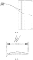
- the cooling medium slantly sprayed from the spray hole 102 flows in the cooling medium communication cavity and sputtered on the flow guide portion 300 of the barrier, the flow guide portion 300 blocks off the cooling medium, changes a direction of the cooling medium outflow line 104 (as shown in Figs.7 to 13 ), and guides the cooling medium sputtered on the flow guide portion 300, so that the flow direction of the cooling medium is changed to being substantially parallel to the axis of the stator winding 2 from being intersected obliquely with the axial direction of the stator winding 2, the cooling medium is divided into two portions, the two portions of the cooling medium flow along the axial inner surface of the coils of the stator winding 2, one portion of the cooling medium flows towards one end of the stator winding 2, and the other portion of the cooling medium flows towards the other end of the stator winding 2, wherein the cooling medium flowing away from the end with the end
- the slot wedge 3 has a slot wedge body of a platy structure
- two flow guide portions 300 are arranged on one side of the slot wedge body and symmetrically arranged on a same side of the slot wedge body.
- the planes where the flow guide portion 300 is located are intersected with the side of the slot wedge body.
- the planes where the two flow guide portions 300 are located are also intersected, so that the two flow guide portions 300 are arranged on a side of the slot wedge body in a raised manner, the joint of the two flow guide portions 300 is in plane transition, so that the two flow guide portion 300 and the slot wedge body constitute a structure with a trapezoid cross section, i.e., the cross section of the slot wedge 3 is of a trapezoid, the flow guide portions 300 and the spray holes 102 are opposite to each other, so that the cooling medium sputtered on the flow guide portions 300 flows towards two directions, and the flow direction of the cooling medium is changed to being substantially parallel to the axis of the stator winding 2 from being slantly intersected with the axial direction of the stator winding 2, the cooling medium is shunted at the end part of the stator winding 2 close to the axial oil feeding device 1 and is divided into two portions, the two portions of the cooling medium flow along the axial inner surface of the coils of the stator winding 2, one
- the height L of the slot wedge 3 is adaptive to that of the stator winding 2, i.e., the height L of the slot wedge 3 is larger than that of teeth of the stator core 4. If the height of the slot wedge 3 is much closer to the heights of ends parts of two sides of the stator winding 2, more cooling media is sputtered on the slot wedge 3, larger amount of the cooling medium is able to be guided to the end parts of the two sides of the stator winding 2, and a corresponding heat contact area is larger.
- the height L of the slot wedge 3 can be selected in accordance with actual requirements and is not particularly limited hereby.
- the width W of the slot wedge 3 is adaptive to that of the stator core 4. If the width W of the slot wedge 3 is much closer to the widths of slots of the stator core 4, more cooling media is gathered on the end part of the stator winding 2 and a dispersive area of the cooling medium is larger.
- the width W of the slot wedge 3 can be selected in accordance with actual requirements and is not particularly limited hereby.
- the frame 8 when the barrier is a frame 8, the frame 8 sleeves on teeth of the stator core 4, frame flow guide portions 800 of adjacent frames 8 blocks off notches of the slots of the stator core 4, so that the stator winding 2 is prevented from departing from the slots of the stator core 4.
- the cooling medium sputtered on the frame flow guide portions 800 of the frames flows towards two directions, the flow direction of the cooling medium is changed to being substantially parallel to the axis of the stator winding 2 from being slantly intersected with the axial direction of the stator winding 2, and the cooling medium is shunted at the end part of the stator winding 2 close to the axial oil feeding device 1 and is divided into two portions, the two portions of the cooling medium flow along the axial inner surface of the coils of the stator winding 2, one portion of the cooling medium flows towards one end of the stator winding 2, and the other portion of the cooling medium flows towards the other end of the stator winding 2, the cooling medium flows through all coils of the stator winding 2 and cools all the coils of the stator winding 2.
- a concentrated winding motor includes a concentrated winding axial cooling motor stator mentioned above.
- the cross section of the oil pipe body 100 is of a square annular structure, i.e., the oil pipe body 100 is in an annular pipe structure, its cross section is square-shaped, and the cross section of an inside cavity is circular.
- the oil pipe body 100 is fixedly mounted in a yoke space at one end of the stator core 4, and arranged on a leading-out terminal 6 of the stator winding 2, one side of the oil pipe body 100 facing the stator winding 2 is provided with a plurality of spray holes, each spray hole 102 corresponds to one slot of the stator core 4, an axis of the spray hole 102 and the axis of the stator winding 2 are slantly intersected, i.e., the cooling medium sprayed out of the spray hole 102 is slantly sprayed to a non-leading-out terminal 7 of the stator winding 2.
- the cooling medium flows in a cooling medium communication cavity to arrive at a slot wedge 3 and to contact with a flow guide portion 300 of the slot wedge 3.
- the cooling medium is shunted to change a direction of the cooling medium outflow line 104, one portion of the cooling medium flows towards the leading-out terminal 6 of the stator winding 2, the other portion of the cooling medium flows towards the non-leading-out terminal 7 of the stator winding 2, and each portion of the cooling medium flows along an axial inner surface of the coils and flows out from the two ends of the stator winding 2, thereby increasing a heat exchange contact area between the cooling medium and the stator winding 2, improving heat dissipation capability, solving the problem that the middle part of the coils of the concentrated winding is quick to temperature rise and a temperature difference between two end parts is large, and increasing power density; meanwhile, the axial
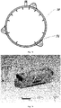
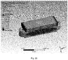
- the results show that the highest temperature of a stator is up to 174°C (at the middle part of the stator) and the highest temperature of a winding at an end part of the stator is 166°C in the solution of radially spraying end parts of a stator and a middle part of a core, while they are respectively 136°C (at the middle part of the stator) and 130°C in the solution of axial gap spraying.
- the axial oil feeding device has an oil pipe body with a cavity in its interior, one side of the oil pipe body facing the stator winding is provided with a plurality of spray holes, the oil pipe body encircles the circumferential side of the stator winding, and the oil pipe body is mounted in a yoke space at any end of the motor stator, the yoke of the stator is fully used, and the yoke and the stator are secured on the casing, so space utilization rate is improved; or the axial oil feeding device is mounted on the casing, or the axial oil feeding device is integrated on the casing, the axial oil feeding device corresponds to the yoke of the stator when the motor stator is mounted, the space inside the casing is fully used, and space utilization rate of the casing is improved.
- the axial oil feeding device is located on the leading-out terminal or non-leading-out terminal of the motor stator, spraying of the cooling medium is carried out on one end of the motor stator, and an axis of the spray hole of an axial cooling structure and the axis of the stator winding are intersected obliquely, so that the cooling medium in the cooling medium outflow line is slantly sprayed towards the other end of the motor stator, blocked off by the barrier in the slot of the stator core after passing through the coils of the stator winding, and shunted by the flow guide portion of the barrier to change its flow direction, therefore, the cooling medium is directly sprayed on the axial inner surface of the coils of the concentrated winding stator, flows along the axial inner surface of the coils towards two ends of the stator winding, and flows out from the two ends, increasing a heat exchange contact area between the cooling medium and the winding, improving heat dissipation capability, solving the problem that the middle part of the concentrated winding coil is quick to temperature
Landscapes
- Engineering & Computer Science (AREA)
- Power Engineering (AREA)
- Motor Or Generator Cooling System (AREA)
Applications Claiming Priority (2)
| Application Number | Priority Date | Filing Date | Title |
|---|---|---|---|
| CN202010518076.9A CN111555503B (zh) | 2020-06-09 | 2020-06-09 | 一种集中绕组轴向冷却电机定子及电机 |
| PCT/CN2021/082826 WO2021248977A1 (fr) | 2020-06-09 | 2021-03-24 | Stator de moteur à refroidissement axial à enroulement concentré et moteur |
Publications (3)
| Publication Number | Publication Date |
|---|---|
| EP4044404A1 true EP4044404A1 (fr) | 2022-08-17 |
| EP4044404A4 EP4044404A4 (fr) | 2022-12-28 |
| EP4044404B1 EP4044404B1 (fr) | 2026-05-06 |
Family
ID=72008672
Family Applications (1)
| Application Number | Title | Priority Date | Filing Date |
|---|---|---|---|
| EP21821636.4A Active EP4044404B1 (fr) | 2020-06-09 | 2021-03-24 | Stator et moteur à refroidissement axial avec enroulement concentré |
Country Status (3)
| Country | Link |
|---|---|
| EP (1) | EP4044404B1 (fr) |
| CN (1) | CN111555503B (fr) |
| WO (1) | WO2021248977A1 (fr) |
Cited By (1)
| Publication number | Priority date | Publication date | Assignee | Title |
|---|---|---|---|---|
| WO2025008078A1 (fr) * | 2023-07-05 | 2025-01-09 | Zf Friedrichshafen Ag | Dispositif d'alimentation en liquide de refroidissement d'une tête d'enroulement à extension axiale d'une machine électrique, boîtier pour machine électrique et véhicule |
Families Citing this family (14)
| Publication number | Priority date | Publication date | Assignee | Title |
|---|---|---|---|---|
| CN111555503B (zh) * | 2020-06-09 | 2025-09-05 | 博格华纳动力驱动系统(天津)有限公司 | 一种集中绕组轴向冷却电机定子及电机 |
| WO2022142483A1 (fr) * | 2020-12-29 | 2022-07-07 | 浙江盘毂动力科技有限公司 | Dispositif de refroidissement de stator de moteur électrique, structure d'évacuation de fluide de refroidissement pour moteur électrique à double stator et moteur électrique |
| CN112821604B (zh) * | 2021-02-09 | 2026-04-14 | 博格华纳动力驱动系统(天津)有限公司 | 一种油冷扁线电机散热结构及电机 |
| CN112769294B (zh) * | 2021-04-07 | 2021-07-20 | 天津市松正电动汽车技术股份有限公司 | 一种油冷扁线电机散热结构及电机 |
| US12101017B2 (en) * | 2021-08-31 | 2024-09-24 | Rivian Ip Holdings, Llc | Coolant fluid sprayer assembly for electric motor |
| CN113612322B (zh) * | 2021-10-08 | 2022-01-11 | 天津市松正电动汽车技术股份有限公司 | 一种油冷电机散热结构及电机 |
| CN116073567A (zh) * | 2021-11-04 | 2023-05-05 | 安徽威灵汽车部件有限公司 | 电机和车辆 |
| CN114211305B (zh) * | 2021-12-22 | 2023-03-21 | 珠海格力电器股份有限公司 | 用于电主轴的轴向和周向联合冷却结构、电主轴和机床 |
| CN114374282B (zh) * | 2022-03-21 | 2022-07-12 | 天津松正汽车部件有限公司 | 一种定子铁芯的散热结构及电机 |
| CN114884277A (zh) * | 2022-05-11 | 2022-08-09 | 珠海格力电器股份有限公司 | 喷射冷却结构、电机及车辆 |
| CN114928212A (zh) * | 2022-05-16 | 2022-08-19 | 珠海格力电器股份有限公司 | 油冷却结构及具有其的新能源车 |
| CN115189519B (zh) * | 2022-07-14 | 2025-01-03 | 深圳十沣科技有限公司 | 一种电机喷油孔控制结构、电机及电机喷油控制方法 |
| CN117175857B (zh) * | 2023-11-02 | 2024-01-09 | 金华市鑫正电机有限公司 | 一种冷却系统及使用该冷却系统的电机 |
| CN118174483B (zh) * | 2024-03-11 | 2024-08-16 | 苏州市职业大学 | 一种低发热量直线电机动子单元 |
Family Cites Families (14)
| Publication number | Priority date | Publication date | Assignee | Title |
|---|---|---|---|---|
| JP2007336646A (ja) * | 2006-06-13 | 2007-12-27 | Toshiba Corp | 回転電機 |
| JP5347380B2 (ja) * | 2008-08-28 | 2013-11-20 | アイシン精機株式会社 | モータの油冷構造 |
| TWI488409B (zh) * | 2012-11-21 | 2015-06-11 | Ind Tech Res Inst | 定子模組及其磁力產生構件 |
| CN204947750U (zh) * | 2015-09-23 | 2016-01-06 | 昆山菱度电机有限公司 | 集中绕组永磁电机的定子结构 |
| JP2017131078A (ja) * | 2016-01-22 | 2017-07-27 | Ntn株式会社 | モータの冷却構造 |
| KR102474505B1 (ko) * | 2016-12-15 | 2022-12-05 | 현대자동차주식회사 | 직접 냉각 방식의 차량용 구동 모터 |
| JP6620128B2 (ja) * | 2017-08-02 | 2019-12-11 | 本田技研工業株式会社 | 回転電機の冷却装置 |
| CN107276266B (zh) * | 2017-08-02 | 2019-04-23 | 华中科技大学 | 一种双向冷却油冷电机 |
| JP6587022B1 (ja) * | 2018-09-05 | 2019-10-09 | 株式会社明電舎 | 回転電機の液冷構造 |
| EP3886299B1 (fr) * | 2018-11-20 | 2024-06-26 | JATCO Ltd | Structure de refroidissement d'huile moteur |
| CN109391088A (zh) * | 2018-12-13 | 2019-02-26 | 上海盘毂动力科技股份有限公司 | 盘式电机及其散热结构 |
| CN210327287U (zh) * | 2019-10-21 | 2020-04-14 | 北京车和家信息技术有限公司 | 一种电机及车辆 |
| CN212462919U (zh) * | 2020-06-09 | 2021-02-02 | 天津市松正电动汽车技术股份有限公司 | 一种集中绕组轴向冷却电机定子及电机 |
| CN111555503B (zh) * | 2020-06-09 | 2025-09-05 | 博格华纳动力驱动系统(天津)有限公司 | 一种集中绕组轴向冷却电机定子及电机 |
-
2020
- 2020-06-09 CN CN202010518076.9A patent/CN111555503B/zh active Active
-
2021
- 2021-03-24 EP EP21821636.4A patent/EP4044404B1/fr active Active
- 2021-03-24 WO PCT/CN2021/082826 patent/WO2021248977A1/fr not_active Ceased
Cited By (1)
| Publication number | Priority date | Publication date | Assignee | Title |
|---|---|---|---|---|
| WO2025008078A1 (fr) * | 2023-07-05 | 2025-01-09 | Zf Friedrichshafen Ag | Dispositif d'alimentation en liquide de refroidissement d'une tête d'enroulement à extension axiale d'une machine électrique, boîtier pour machine électrique et véhicule |
Also Published As
| Publication number | Publication date |
|---|---|
| EP4044404A4 (fr) | 2022-12-28 |
| CN111555503A (zh) | 2020-08-18 |
| EP4044404B1 (fr) | 2026-05-06 |
| CN111555503B (zh) | 2025-09-05 |
| WO2021248977A1 (fr) | 2021-12-16 |
Similar Documents
| Publication | Publication Date | Title |
|---|---|---|
| EP4044404B1 (fr) | Stator et moteur à refroidissement axial avec enroulement concentré | |
| CN113612322B (zh) | 一种油冷电机散热结构及电机 | |
| US12418206B2 (en) | Stator core, motor, power assembly, automobile and vehicle | |
| CN112821604A (zh) | 一种油冷扁线电机散热结构及电机 | |
| WO2022001268A1 (fr) | Moteur, système de refroidissement de moteur et véhicule électrique | |
| JP2022527245A (ja) | モータ、モータ冷却システム、および電動車両 | |
| CN112953047B (zh) | 一种阶梯斜槽的扁铜线油冷电机定子及电机 | |
| CN115173632A (zh) | 高压油冷电驱动总成装置 | |
| CN212462919U (zh) | 一种集中绕组轴向冷却电机定子及电机 | |
| EP4131727B1 (fr) | Structure de stator et moteur à câble plat | |
| KR20180032616A (ko) | 전기 기계를 위한 냉각 시스템 | |
| CN121124419A (zh) | 包括冷却管道的转子、转子成型方法以及电机冷却系统 | |
| CN216162491U (zh) | 一种油冷电机散热结构及电机 | |
| CN116404775A (zh) | 一种油冷轴向磁通电机 | |
| CN214900380U (zh) | 一种新型阶梯斜槽的扁铜线油冷电机定子及电机 | |
| CN219068015U (zh) | 一种电机的油冷结构及电机 | |
| CN214412433U (zh) | 一种油冷扁线电机散热结构及电机 | |
| CN117353521B (zh) | 一种电机驱动系统及汽车 | |
| CN113708550B (zh) | 一种电机 | |
| CN112928838A (zh) | 折流风冷式的发电机定子及具有高转矩密度的发电机 | |
| CN114374282B (zh) | 一种定子铁芯的散热结构及电机 | |
| CN211981621U (zh) | 一种新能源汽车、电机及电机壳体 | |
| CN220440497U (zh) | 定子的冷却结构、壳体、电机及车辆 | |
| CN220421511U (zh) | 电机及具有该电机的动力设备 | |
| CN219999162U (zh) | 一种油冷电机 |
Legal Events
| Date | Code | Title | Description |
|---|---|---|---|
| STAA | Information on the status of an ep patent application or granted ep patent |
Free format text: STATUS: THE INTERNATIONAL PUBLICATION HAS BEEN MADE |
|
| PUAI | Public reference made under article 153(3) epc to a published international application that has entered the european phase |
Free format text: ORIGINAL CODE: 0009012 |
|
| STAA | Information on the status of an ep patent application or granted ep patent |
Free format text: STATUS: REQUEST FOR EXAMINATION WAS MADE |
|
| 17P | Request for examination filed |
Effective date: 20220428 |
|
| AK | Designated contracting states |
Kind code of ref document: A1 Designated state(s): AL AT BE BG CH CY CZ DE DK EE ES FI FR GB GR HR HU IE IS IT LI LT LU LV MC MK MT NL NO PL PT RO RS SE SI SK SM TR |
|
| RAP3 | Party data changed (applicant data changed or rights of an application transferred) |
Owner name: BORGWARNER POWERDRIVE SYSTEMS(TIANJIN) CO., LTD. |
|
| A4 | Supplementary search report drawn up and despatched |
Effective date: 20221125 |
|
| RIC1 | Information provided on ipc code assigned before grant |
Ipc: H02K 9/19 20060101ALI20221121BHEP Ipc: H02K 1/20 20060101ALI20221121BHEP Ipc: H02K 3/24 20060101AFI20221121BHEP |
|
| DAV | Request for validation of the european patent (deleted) | ||
| DAX | Request for extension of the european patent (deleted) | ||
| GRAP | Despatch of communication of intention to grant a patent |
Free format text: ORIGINAL CODE: EPIDOSNIGR1 |
|
| STAA | Information on the status of an ep patent application or granted ep patent |
Free format text: STATUS: GRANT OF PATENT IS INTENDED |
|
| INTG | Intention to grant announced |
Effective date: 20251107 |
|
| GRAS | Grant fee paid |
Free format text: ORIGINAL CODE: EPIDOSNIGR3 |
|
| GRAA | (expected) grant |
Free format text: ORIGINAL CODE: 0009210 |
|
| STAA | Information on the status of an ep patent application or granted ep patent |
Free format text: STATUS: THE PATENT HAS BEEN GRANTED |
|
| AK | Designated contracting states |
Kind code of ref document: B1 Designated state(s): AL AT BE BG CH CY CZ DE DK EE ES FI FR GB GR HR HU IE IS IT LI LT LU LV MC MK MT NL NO PL PT RO RS SE SI SK SM TR |
|
| REG | Reference to a national code |
Ref country code: CH Ref legal event code: F10 Free format text: ST27 STATUS EVENT CODE: U-0-0-F10-F00 (AS PROVIDED BY THE NATIONAL OFFICE) Effective date: 20260506 Ref country code: GB Ref legal event code: FG4D |