EP4044543A1 - Procédé et dispositif de transmission de paquets de données - Google Patents
Procédé et dispositif de transmission de paquets de données Download PDFInfo
- Publication number
- EP4044543A1 EP4044543A1 EP19947563.3A EP19947563A EP4044543A1 EP 4044543 A1 EP4044543 A1 EP 4044543A1 EP 19947563 A EP19947563 A EP 19947563A EP 4044543 A1 EP4044543 A1 EP 4044543A1
- Authority
- EP
- European Patent Office
- Prior art keywords
- rlc channel
- configuration information
- data payload
- channel
- packet
- Prior art date
- Legal status (The legal status is an assumption and is not a legal conclusion. Google has not performed a legal analysis and makes no representation as to the accuracy of the status listed.)
- Pending
Links
Images


Classifications
-
- H—ELECTRICITY
- H04—ELECTRIC COMMUNICATION TECHNIQUE
- H04W—WIRELESS COMMUNICATION NETWORKS
- H04W40/00—Communication routing or communication path finding
- H04W40/24—Connectivity information management, e.g. connectivity discovery or connectivity update
- H04W40/248—Connectivity information update
-
- H—ELECTRICITY
- H04—ELECTRIC COMMUNICATION TECHNIQUE
- H04L—TRANSMISSION OF DIGITAL INFORMATION, e.g. TELEGRAPHIC COMMUNICATION
- H04L9/00—Cryptographic mechanisms or cryptographic arrangements for secret or secure communications; Network security protocols
- H04L9/40—Network security protocols
-
- H—ELECTRICITY
- H04—ELECTRIC COMMUNICATION TECHNIQUE
- H04W—WIRELESS COMMUNICATION NETWORKS
- H04W40/00—Communication routing or communication path finding
- H04W40/02—Communication route or path selection, e.g. power-based or shortest path routing
- H04W40/22—Communication route or path selection, e.g. power-based or shortest path routing using selective relaying for reaching a BTS [Base Transceiver Station] or an access point
-
- H—ELECTRICITY
- H04—ELECTRIC COMMUNICATION TECHNIQUE
- H04W—WIRELESS COMMUNICATION NETWORKS
- H04W88/00—Devices specially adapted for wireless communication networks, e.g. terminals, base stations or access point devices
- H04W88/08—Access point devices
- H04W88/085—Access point devices with remote components
Definitions
- This application relates to the field of wireless communications technologies, and in particular, to a data packet transmission method and apparatus.
- An integrated access and backhaul (integrated access and backhaul, IAB) network technology is introduced into a 5th generation (5th generation, 5G) mobile communications system.
- a wireless transmission solution is used for both an access link (access link) and a backhaul link (backhaul link) in an IAB network, to avoid optical fiber deployment, so as to reduce deployment costs and improve deployment flexibility.
- the IAB network includes an IAB node (IAB node) and an IAB donor (IAB donor).
- a terminal side device may access the IAB node, and traffic data of the terminal side device may be transmitted from the IAB node to the IAB donor through a wireless backhaul link.
- Implementations of this application provide a data packet transmission method and apparatus, to resolve a corresponding problem of how to perform bear mapping for a data payload on a backhaul link.
- an embodiment of this application provides a data packet transmission method, including: An IAB donor determines first configuration information, where the first configuration information is used to indicate a first BH RLC channel, and the first BH RLC channel is used to transmit a control PDU at a BAP layer.
- the IAB donor sends the first configuration information to an IAB node.
- the IAB donor indicates, by using the first configuration information, the IAB node to send the control PDU at the BAP layer through the first BH RLC channel, to implement bearer mapping when the IAB node needs to send the control PDU at the BAP layer.
- the first configuration information includes a channel identifier of the first BH RLC channel; or the first configuration information includes a logical channel identifier, and a logical channel indicated by the logical channel identifier corresponds to the first BH RLC channel.
- a data packet transmission method includes: An IAB node determines a first BH RLC channel used to transmit a control PDU at a BAP layer. The IAB node sends the control PDU at the BAP layer to an adjacent node of the IAB node through the first BH RLC channel.
- an IAB donor indicates, by using first configuration information, the IAB node to send the control PDU at the BAP layer through the first BH RLC channel, to implement bearer mapping when the IAB node needs to send the control PDU at the BAP layer.
- an IAB node determines a first backhaul link BH RLC channel used to transmit a control PDU at a BAP layer includes: The IAB node obtains first configuration information from an IAB donor, where the first configuration information is used to indicate the first BH RLC channel used to transmit the control PDU at the BAP layer. The IAB node determines the first BH RLC channel based on the first configuration information.
- the first configuration information includes a channel identifier of the first BH RLC channel; or the first configuration information includes a logical channel identifier, and a logical channel indicated by the logical channel identifier corresponds to the first BH RLC channel.
- a data packet transmission method includes: An IAB donor determines second configuration information, where the second configuration information is used to indicate a second backhaul link BH radio link control RLC channel, the second BH RLC channel is used to transmit a first-type data payload, and the first-type data payload is a data payload other than an F1 user plane F1-U data payload and an F1 control plane F1-C data payload.
- the IAB donor sends the second configuration information to an IAB node.
- the IAB donor indicates, by using the second configuration information, the IAB node to send the first-type data payload through the second BH RLC channel, to implement bearer mapping on the first-type data payload.
- the first-type data payload includes any one of the following: an operation, administration, and maintenance OAM traffic packet; a packet used to request an internet protocol IP address; a packet used to establish an internet protocol security IPsec transmission channel; a stream control transport protocol SCTP association setup packet; an SCTP association shutdown packet; and an SCTP association heartbeat packet.
- the second configuration information includes any one or more of the following: a first type, where the first type is a type of a data payload, and the first type corresponds to the second BH RLC channel; first differentiated service information, where the first differentiated service information corresponds to the first type and/or the second BH RLC channel; and a first flow label, where the first flow label corresponds to the first type and/or the second BH RLC channel.
- the method further includes: The IAB donor generates a first data payload, where the first data payload is the first-type data payload. If packet header information corresponding to the first data payload carries the first differentiated service information, the IAB donor sends a first data packet to the IAB node through the second BH RLC channel corresponding to the first differentiated service information; or if packet header information corresponding to the first data payload carries the first flow label, the IAB donor sends a first data packet to the IAB node through the second BH RLC channel corresponding to the first flow label, where the first data packet includes the first data payload.
- the second configuration information includes identification information used to identify the second BH RLC channel, and the identification information is a channel identifier of the second BH RLC channel, or the identification information is a logical channel identifier corresponding to the second BH RLC channel.
- a data packet transmission method includes: An IAB node receives second configuration information from an IAB donor, where the second configuration information is used to indicate a second backhaul link BH radio link control RLC channel, the second BH RLC channel is used to transmit a first-type data payload, and the first-type data payload is a data payload other than an F1 user plane F1-U data payload and an F1 control plane F1-C data payload.
- the IAB node transmits the first-type data payload based on the second configuration information.
- the IAB node determines, by using the second configuration information sent by the IAB donor, that the first-type data payload is sent through the second BH RLC channel, to implement bearer mapping on the first-type data payload.
- the first-type data payload includes any one of the following: an operation, administration, and maintenance OAM traffic packet; a packet used to request an internet protocol IP address; a packet used to establish an internet protocol security IPsec transmission channel; a stream control transport protocol SCTP association setup packet; an SCTP association shutdown packet; and an SCTP association heartbeat packet.
- the second configuration information includes any one or more of the following: a first type, where the first type is a type of a data payload, and the first type corresponds to the second BH RLC channel; first differentiated service information, where the first differentiated service information corresponds to the first type and/or the second BH RLC channel; and a first flow label, where the first flow label corresponds to the first type and/or the second BH RLC channel.
- the second configuration information includes identification information used to identify the second BH RLC channel, and the identification information is a channel identifier of the second BH RLC channel, or the identification information is a logical channel identifier corresponding to the second BH RLC channel.
- a data packet transmission method includes: An IAB donor determines a first label based on packet header information corresponding to a third data payload, where the first label is used to determine an egress radio link control RLC channel of the third data payload.
- the IAB donor sends a third data packet to an IAB node, where the third data packet includes the third data payload and a first backhaul adaptation protocol BAP layer header, and the first BAP layer header includes the first label.
- the IAB donor uses the first label to indicate the egress radio link control RLC channel of the third data payload, and no longer determines the egress RLC channel of the third data payload based on only an ingress RLC channel of the third data payload, to implement flexible transmission of the third data payload.
- an IAB donor determines a first label based on packet header information corresponding to a third data payload includes:
- the IAB donor obtains third configuration information.
- the IAB donor determines the first label based on the packet header information corresponding to the third data payload and the third configuration information, where the third configuration information is used to configure a correspondence between first information in the packet header information and the first label, and the first information includes any one or more of the following: first differentiated service information, a first flow label, and a first internet protocol IP address.
- a data packet transmission method includes: A second IAB node obtains a fourth data payload.
- the second IAB node determines a second label based on packet header information corresponding to the fourth data payload or a message type corresponding to the fourth data payload, where the second label is used to determine an egress radio link control RLC channel of the fourth data payload.
- the second IAB node sends a fourth data packet to a first IAB node, where the fourth data packet includes the fourth data payload and a second backhaul adaptation protocol BAP layer header, and the second BAP layer header includes the second label.
- that the second IAB node determines a second label based on packet header information corresponding to the fourth data payload includes:
- the second IAB node receives fourth configuration information from an IAB donor.
- the second IAB node determines the second label based on the packet header information corresponding to the fourth data payload and the fourth configuration information.
- the fourth configuration information is used to configure a correspondence between second information in the packet header information and the second label
- the second information includes any one or more of the following: second differentiated service information in the packet header information, a second flow label in the packet header information, a second IP address in the packet header information, data radio bearer information that is in the packet header information and that corresponds to the fourth data payload, a second type of the fourth data payload, and a stream identifier at an SCTP layer that carries an F1AP message when the fourth data payload is the F1AP message.
- that the second IAB node determines a second label based on a message type corresponding to the fourth data payload includes:
- the second IAB node receives fourth configuration information from an IAB donor.
- the second IAB node determines the second label from the fourth configuration information based on the message type corresponding to the fourth data payload.
- the fourth data payload is a control plane F1 application protocol F1AP message
- the fourth configuration information includes one or more of the following: a second type of the fourth data payload and a second label corresponding to the second type, where the second type is any one or more of F1AP message types: a stream identifier at an SCTP layer that carries the F1AP message when the fourth data payload is the F1AP message, and a second label corresponding to the stream identifier.
- a data packet transmission method includes: A first integrated access and backhaul IAB node obtains a data packet, where the data packet is a data packet from a second IAB node or a data packet from an IAB donor, a backhaul adaptation protocol BAP layer header of the data packet includes a third label, and the third label is used to determine an egress radio link control RLC channel of the data packet.
- the first IAB node determines a third RLC channel identifier based on the third label, where the third RLC channel identifier is an identifier of the egress RLC channel of the data packet.
- the first IAB node sends the data packet through the egress RLC channel corresponding to the third RLC channel identifier.
- that the first IAB node determines a third RLC channel identifier based on the third label includes: The first IAB node receives fifth configuration information from the IAB donor, where the fifth configuration information is used to configure a correspondence between the third label and the third RLC channel identifier.
- the first IAB node determines, as the third RLC channel identifier, an RLC channel identifier that is in the fifth configuration information and that corresponds to the third label.
- the first IAB node determines, as the third RLC channel identifier, an RLC channel identifier that is in the fifth configuration information and that corresponds to the third label and a fourth RLC channel identifier, where the fourth RLC channel identifier is an identifier of an ingress RLC channel for receiving the data packet.
- the first IAB node determines, from the fifth configuration information, a first quality of service QoS identifier corresponding to the third label, and determines, as the third RLC channel identifier, an RLC channel identifier that is in the fifth configuration information and that corresponds to the first QoS identifier.
- the first IAB node determines, from the fifth configuration information, a first QoS parameter corresponding to the third label, and determines, as the third RLC channel identifier, an RLC channel identifier that is in the fifth configuration information and that corresponds to the first QoS parameter.
- the fifth configuration information includes any one or more of the following:
- this application further provides a communications apparatus.
- the communications apparatus has a function of implementing any method provided in any one of the foregoing aspects.
- the communications apparatus may be implemented by hardware, or may be implemented by hardware executing corresponding software.
- the hardware or the software includes one or more units corresponding to the foregoing function.
- the communications apparatus includes a processor, and the processor is configured to support the communications apparatus in performing corresponding functions of the first IAB node, the second IAB node, the IAB donor, or the IAB node in the foregoing method.
- the communications apparatus may further include a memory, and the memory may be coupled to the processor, and stores program instructions and data that are necessary for the communications apparatus.
- the communications apparatus further includes a communications interface, and the communications interface is configured to support communication between the communications apparatus and a device such as the first IAB node, the second IAB node, the IAB donor, or the IAB node.
- the communication apparatus includes corresponding functional units, respectively configured to implement the steps in the foregoing method.
- a function may be implemented by hardware, or may be implemented by hardware executing corresponding software.
- the hardware or the software includes one or more units corresponding to the foregoing function.
- a structure of the communications apparatus includes a processing unit and a communications unit. These units may perform corresponding functions in the foregoing method examples. For details, refer to descriptions in the method according to any one of the foregoing aspects. The details are not described herein again.
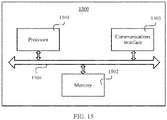
- this application provides a communications apparatus, including a processor and a memory.
- the memory is configured to store computer-executable instructions, and when the apparatus runs, the processor executes the computer-executable instructions stored in the memory, so that the apparatus performs the methods in the foregoing aspects.
- this application provides a communications apparatus, including a unit or a means (means) configured to perform the steps in the foregoing aspects.
- this application provides a communication apparatus, including a processor and a communications interface.
- the processor is configured to: communicate with another apparatus through the communications interface, and perform the methods in the foregoing aspects.
- this application provides a communications apparatus, including a processor, configured to: connect to at least one memory, and invoke a program stored in the at least one memory, to perform the methods in the foregoing aspects.
- the at least one memory may be located inside the apparatus, or may be located outside the apparatus.
- this application further provides a computer-readable storage medium.
- the computer-readable storage medium stores instructions, and when the instructions are run on a computer, the computer is enabled to perform the methods in the foregoing aspects.
- this application further provides a computer program product including instructions, and when the computer program product runs on a computer, the computer is enabled to perform the methods in the foregoing aspects.
- this application further provides a chip system, including a processor, configured to perform the methods in the foregoing aspects.
- this application further provides a chip system, including the first IAB node, the second IAB node, and the IAB donor that are provided above.
- the embodiments of this application may be applied to various mobile communications systems, for example, a new radio (new radio, NR) system, a long term evolution (long term evolution, LTE) system, a long term evolution-advanced (long term evolution-advanced, LTE-A) system, an evolved long term evolution (evolved long term evolution, eLTE) system, a future communications system, and another communications system.
- a new radio new radio
- NR new radio
- LTE long term evolution
- LTE-A long term evolution-advanced
- eLTE evolved long term evolution
- future communications system evolved long term evolution
- a terminal side device is a device having a wireless transceiver function or a chip that can be disposed in the device.
- the device having the wireless transceiver function may also be referred to as user equipment (user equipment, UE), an access terminal, a subscriber unit, a subscriber station, a mobile station, a remote station, a remote terminal, a mobile device, a user terminal, a user agent, or a user apparatus.
- user equipment user equipment
- the terminal side device in the embodiments of this application may be a mobile phone (mobile phone), a tablet computer (Pad), a computer having a wireless transceiver function, a virtual reality (virtual reality, VR) terminal, an augmented reality (augmented reality, AR) terminal, a wireless terminal in industrial control (industrial control), a wireless terminal in self driving (self driving), a wireless terminal in remote medical (remote medical), a wireless terminal in a smart grid (smart grid), a wireless terminal in transportation safety (transportation safety), a wireless terminal in a smart city (smart city), a wireless terminal in a smart home (smart home), or the like.
- An application scenario is not limited in the embodiments of this application.
- the device having the wireless transceiver function and the chip that can be disposed in the device are collectively referred to as the terminal side device.
- a network side device may be a radio access device in various standards, for example, an evolved NodeB (evolved NodeB, eNB), a radio network controller (radio network controller, RNC), a NodeB (NodeB, NB), a base station controller (base station controller, BSC), a base transceiver station (base transceiver station, BTS), a home base station (for example, a home evolved NodeB, or a home NodeB, HNB), a baseband unit (baseband unit, BBU), an access point (access point, AP) in a wireless fidelity (wireless fidelity, Wi-Fi) system, a wireless relay node, a wireless backhaul node, or a transmission point (transmission reception point, TRP or transmission point, TP).
- RNC radio network controller
- NodeB NodeB
- BSC base station controller
- BTS base transceiver station
- home base station for example, a home evolved NodeB, or a home No
- the network side device may alternatively be a gNB or a transmission point (TRP or TP) in a 5G (NR) system, one or a group of antenna panels (including a plurality of antenna panels) of a base station in a 5G system, a network node that constitutes a gNB or a transmission point, for example, a baseband unit (BBU), a DU or a CU in a central unit-distributed unit (central unit-distributed unit, CU-DU) architecture, or the like.
- BBU baseband unit
- DU central unit-distributed unit
- CU-DU central unit-distributed unit
- an IAB scenario in a wireless communications network is used as an example to describe some scenarios. It should be noted that the solutions in the embodiments of this application may be further applied to another wireless communications network, and a corresponding name may also be replaced with a name of a corresponding function in the another wireless communications network.
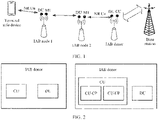
- FIG. 1 is a schematic diagram of a communications system to which an embodiment of this application is applicable.
- the communications system includes a base station, an IAB donor, an IAB node 1, an IAB node 2, and a terminal side device.
- a node that supports integrated access and backhaul is referred to as an IAB node, and the IAB node may also be referred to as a relay node (relay node, RN).
- relay node relay node
- both the node and the relay node are referred to as the IAB node below.
- the IAB node may provide a wireless access service for the terminal side device, and traffic data or control information of the terminal side device is transmitted from the IAB node to the IAB donor (IAB donor) or another network side device through a wireless backhaul link.
- the IAB node may include at least one mobile terminal (mobile terminal, MT) unit and at least one distributed unit (distributed unit, DU).
- the IAB node includes one MT unit and one DU is used for description.
- the MT unit in the IAB node implements that the IAB node serves as a terminal to communicate with a parent node of the IAB node and the IAB donor.
- the DU in the IAB node provides an access service for a terminal side device or another IAB node attached to the DU, and may also communicate with the IAB donor through an F1 interface.
- the MT unit in the IAB node may also be referred to as an MT function entity in the IAB node, and the DU in the IAB node may also be referred to as a DU function entity in the IAB node.
- both the MT unit in the IAB node and the MT function entity in the IAB node are briefly referred to as an "IAB node MT", and both the DU in the IAB node and the DU function entity in the IAB node are briefly referred to as an "IAB node DU”.
- the IAB donor may be an access network element having a complete base station function, or may be an access network element in a form in which a centralized unit (centralized unit, CU) and a distributed unit (distributed unit, DU) are separated.
- a centralized unit centralized unit, CU
- a distributed unit distributed unit
- FIG. 2 an IAB donor CU may alternatively be in a form in which a control plane (control plane, CP) and a user plane (user plane, UP) are separated.
- control plane, CP control plane
- UP user plane
- one IAB donor CU includes one CU-CP and a plurality of CU-UPs. This is not limited in this embodiment of this application.
- a CU in the IAB donor may also be referred to as a CU function entity in the IAB donor, and a DU in the IAB donor may also be referred to as a DU function entity in the IAB donor.
- the CU in the IAB donor and the CU function entity in the IAB donor are briefly referred to as an IAB donor CU, and the DU in the IAB donor and the DU function entity in the IAB donor are briefly referred to as an IAB donor DU.
- FIG. 1 further shows names of interfaces between devices.
- the names of the interfaces are merely examples, and do not represent a limitation on the interface.
- a corresponding name may also be replaced with a name of a corresponding function in another wireless communications network.
- an interface between the IAB donor and the base station may be an Xn interface.
- an interface between the IAB donor and the base station may be an X2 interface.
- An IAB network shown in FIG. 1 supports multi-hop networking.
- there is an intermediate IAB node that is, the IAB node 2 between the IAB node 1 and the IAB donor shown in FIG. 1 .
- the IAB node 1 may also be directly connected to the IAB donor without other intermediate IAB nodes, or there may be more than one intermediate IAB node between the IAB node 1 and the IAB donor.
- the IAB network shown in FIG. 1 supports both multi-hop networking and multi-connection networking. At least one transmission path including a plurality of links may exist between the terminal side device served by the IAB node and the IAB donor. There may also be one or more transmission paths between the IAB node and the IAB donor, and each transmission path may include one or more IAB nodes. On a transmission path, each IAB node considers an adjacent node that provides a backhaul service for the IAB node as a parent node, and correspondingly, each IAB node may be considered as a child node of the parent node of the IAB node. For example, in the scenario shown in FIG. 1 , a parent node of the IAB node 2 is the IAB donor, and the IAB donor considers the IAB node 2 as a child node.
- the terminal side device served by the IAB node may establish a connection to the IAB node, and may also be directly connected to the base station (an evolved NodeB eNB in an LTE network) through a Uu interface in LTE.
- the IAB node may be connected to the base station through the Uu interface in LTE, and may also be connected to the IAB donor through a one-hop or multi-hop NR wireless backhaul link.
- the IAB donor and the base station are connected through an X2 interface.
- some technical terms may be used, for example, a previous-hop node of the node, a next-hop node of the node, an ingress link (ingress link) of the node, and an egress link (egress link) of the node.
- a previous-hop node of the node a next-hop node of the node
- an ingress link (ingress link) of the node a next-hop node of the node
- egress link egress link
- Previous-hop node of a node is the last node that is on a path including the node and that receives a data packet before the node.
- Next-hop node of a node is the 1 st node that is on a path including the node and that receives a data packet after the node.
- the ingress link of the node is a link between the node and a previous-hop node of the node, and may also be referred to as a previous-hop link of the node.
- the egress link of a node is a link between the node and a next-hop node of the node, and may also be referred to as a next-hop link of the node.
- Each IAB node considers a node that provides a wireless access service and/or a wireless backhaul service for the IAB node as a parent node (parent node).
- each IAB node may be considered as a child node (child node) of the parent node of the IAB node.
- the child node may also be referred to as a lower-level node, and the parent node may also be referred to as an upper-level node.
- the F1 interface in this embodiment of this application is an interface between the IAB node DU and the IAB donor or the IAB donor CU.
- the F1 interface may also be referred to as a name such as an F1 ⁇ interface.
- the interfaces may be collectively referred to as the F1 interface, but the name is not limited.
- the F1 interface may also be an interface between function entities in a device.
- the F1 interface may be an interface between the DU in the base station and the CU in the base station.
- the F1 interface supports a user plane protocol and a control plane protocol.
- a user plane protocol layer of the F1 interface includes a general packet radio service (General Packet Radio Service, GPRS) tunneling protocol user plane (GPRS Tunneling Protocol User Plane, GTP-U) layer, a user datagram protocol (user datagram protocol, UDP) layer, and an internet protocol (internet protocol, IP) layer.
- GPRS General Packet Radio Service
- GTP-U General Packet Radio Service
- UDP user datagram protocol
- IP internet protocol
- the user plane protocol layer of the F1 interface further includes a PDCP layer and/or an IP security (IP Security, IPsec for short) layer.
- IP Security IP Security
- a control plane protocol layer of the F1 interface includes an F1 application protocol (F1 application protocol, F1AP) layer, a stream control transport protocol (stream control transport protocol, SCTP) layer, and an IP layer.
- the control plane protocol layer of the F1 interface further includes one or more of a PDCP layer, an IPsec layer, and a datagram transport layer security (datagram transport layer security, DTLS for short) layer.
- first, second, third, and the like may be added before the terms to describe various messages and information, for example, first configuration information, second configuration information, and third configuration information, “first”, “second”, “third”, and the like are only used to distinguish between the messages, the information, and the like, and do not mean that the messages, the information, and the like are limited.
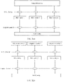
- FIG. 3(a) and FIG. 3(b) each are a schematic diagram of a correspondence between an RLC channel, a logical channel (logical channel, LCH), and a protocol entity.
- the radio link control (radio link control, RLC) channel channel (channel) is a channel between an RLC entity and an upper-layer protocol entity of the RLC entity.
- RLC radio link control
- the RLC channel on a backhaul link is a channel between the RLC entity and the PDCP entity.
- an upper layer of the RLC entity is a backhaul adaptation protocol (Backhaul Adaptation Protocol, BAP) entity
- BAP Backhaul Adaptation Protocol
- the RLC channel on a backhaul link is a channel between the RLC entity and the BAP entity. Therefore, the RLC channel is specifically determined by the upper-layer protocol entity of the RLC entity.
- the logical channel is a channel between the RLC entity and a lower-layer protocol entity of the RLC entity. For example, if a lower layer of the RLC entity is a MAC layer, the logical channel is a channel between the RLC entity and the MAC entity.
- the RLC channel of the IAB node one-by-one corresponds to a RLC entity, and also one-by-one corresponds to a RLC bearer.
- one BAP entity may correspond to a plurality of RLC entities, or as shown in FIG. 3(b) , one BAP entity may correspond to one RLC entity. This is not limited in this application.
- a BAP layer has one or more of the following capabilities: adding, to a data packet, routing information (routing information) that can be identified by a wireless backhaul node (IAB node); performing routing selection based on the routing information that can be identified by the wireless backhaul node; adding, to the data packet, identification information that can be identified by the wireless backhaul node and that is related to a quality of service (quality of service, QoS) requirement; performing QoS mapping on the data packet on a plurality of links including the wireless backhaul node; adding data packet type indication information to the data packet; and sending flow control feedback information to a node having a flow control capability.
- routing information routing information
- IAB node wireless backhaul node
- QoS quality of service
- An RLC channel on a BH link may be understood as a traffic differentiation channel on the BH link between two nodes, and the service differentiation channel may provide specific quality of service QoS guarantee for data packet transmission.
- the RLC channel on the BH link may be understood as a logical channel instead of a physical channel.
- a BH RLC channel that is, the RLC channel on the BH link
- the traffic differentiation channel may provide specific quality of service (quality of service, QoS) guarantee for data packet transmission.
- QoS quality of service
- the RLC channel on the BH link may be understood as a logical channel instead of a physical channel.
- the RLC channel on the BH link may be understood as peer RLC channels of two adjacent nodes that are connected on the BH link.
- the IAB donor DU has an RLC channel 1 and an RLC channel 2
- the IAB node 1 has an RLC channel 1 and an RLC channel 2.
- the RLC channel 1 of the IAB donor DU is a peer of the RLC channel 1 of the IAB node 1
- the RLC channel 2 of the IAB donor DU is a peer (peer) of the RLC channel 2 of the IAB node 1.
- the RLC channel 1 on the BH link between the IAB donor DU and the IAB node 1 may be the RLC channel 1 of the IAB donor DU and the RLC channel 1 of the IAB node 1
- the RLC channel 2 on the BH link between the IAB donor DU and the IAB node 1 may be the RLC channel 2 of the IAB donor DU and the RLC channel 2 of the IAB node 1.
- RLC channels, RLC bearers, and logical channels are in a one-to-one correspondence, in this embodiment of this application, the three descriptions may substitute for each other.
- the RLC channel may be replaced with the RLC bearer or the logical channel.
- the RLC channel on the BH link may be replaced with an RLC bearer on the BH link or a logical channel on the BH link.
- the RLC bearer on the BH link may also be referred to as a BH bearer or a BH link bearer.
- an RLC channel used when a node receives a data packet may also be referred to as an ingress RLC channel (ingress RLC channel), and an RLC channel used when a data packet is sent is referred to as an egress RLC channel (egress RLC channel).
- ress RLC channel an RLC channel used when a data packet is sent
- egress RLC channel an RLC channel used when a data packet is sent
- data payloads transmitted between the IAB node and the donor node may include an F1 traffic data payload and a non-F 1 traffic (non-F 1 traffic) data payload.
- the F1 traffic data payload includes an F1 user plane (F1-U) data payload or an F1 control plane (F1-C) data payload.
- the non-F 1 traffic data payload may include data payloads other than the F1 user plane data payload and the F1 control plane data payload.
- the non-F 1 traffic data payload may be in a plurality of forms.
- the non-F 1 traffic data payload may include a control (control) protocol data unit (Protocol Data Unit, PDU) at a BAP layer, an operation, administration, and maintenance (Operation, Administration, and Maintenance, OAM) traffic data packet of the IAB node (which may be the IAB node DU in a specific implementation), a data packet sent when stream control transport protocol (stream control transport protocol, SCTP) association (association) is established between the IAB node (which may be the IAB node DU in a specific implementation) and the IAB donor or when SCTP association is maintained, and a data packet involved when an internet protocol security (Internet Protocol Security, IPsec) transmission channel is established between the IAB node (which may be the IAB node DU in a specific implementation) and the IAB donor.
- a control (control) protocol data unit (Protocol Data Unit, PDU) at a BAP layer an operation, administration, and maintenance (Oper
- An embodiment of this application provides a method, to perform bearer mapping on the non-F 1 traffic data payload on the wireless backhaul link. Descriptions are provided below.
- a control PDU at a BAP layer is transmitted between an IAB node and an IAB donor.
- the control PDU at the BAP layer may be considered as a non-F1 traffic data packet, and a data payload carried in the control PDU is a data payload other than an F1 user plane data payload and an F1 control plane data payload.
- the control PDU at the BAP layer is exchanged between two adjacent nodes.
- a child node sends the control PDU to a parent node
- a parent node sends the control PDU to a child node.
- the child node may be the IAB node
- the parent node may be another IAB node
- the parent node may be the IAB donor (which may be an IAB donor DU in a specific implementation).
- the control PDU at the BAP layer may include hop-by-hop control information, for example, include feedback information used for flow control, or include a notification that a wireless backhaul link is abnormal and that is sent by the parent node to the child node.
- the abnormality of the wireless backhaul link may be a radio link failure (radio link failure, RLF for short), blockage (blockage), or congestion (congestion) of the wireless backhaul link, or may be a connection that is of the wireless backhaul link and that cannot be recovered, or the like.
- RLF radio link failure
- blockage blockage
- congestion congestion
- This control PDU at the BAP layer does not need to be encapsulated in an IP packet.
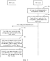
- FIG. 4 is a schematic flowchart of a data packet transmission method according to an embodiment of this application. Refer to FIG. 4 . The method includes the following steps.
- Step 401 An IAB donor determines first configuration information.
- the first configuration information is used to indicate a first BH RLC channel, and the first BH RLC channel is used to transmit a control PDU at a BAP layer.
- Step 402 The IAB donor sends the first configuration information to an IAB node.
- the IAB donor may send the first configuration information by using a control plane message such as an F1AP message or an RRC message.
- the IAB donor (which may be an IAB donor DU or an IAB donor CU in a specific implementation) may receive the first configuration information from OAM of the IAB node, and then send the first configuration information to the IAB node.
- the IAB donor may also send the first configuration information to the parent node of the IAB node.
- a specific process may be the same as a process of sending the first configuration information to the IAB node. Details are not described herein again.
- steps 401 and 402 may be performed by the IAB donor CU. If the IAB donor includes the CU and the DU, the IAB donor CU may further configure the first configuration information for the IAB donor DU.
- steps 401 and 402 may be performed by the IAB donor CU-CP.
- Step 403 The IAB node receives the first configuration information from the IAB donor.
- Step 404 The IAB node determines, based on the first configuration information, the first BH RLC channel used to transmit the control PDU at the BAP layer.
- Step 405 The IAB node sends the control PDU at the BAP layer to an adjacent node of the IAB node through the first BH RLC channel.
- the adjacent node of the IAB node may be, for example, a parent node (the parent node may be another IAB node or the IAB donor (which may be the IAB donor DU in a specific implementation in which the IAB donor is in an architecture in which the CU and the DU are separated)) of the IAB node, or a child node of the IAB node.
- the parent node may be another IAB node or the IAB donor (which may be the IAB donor DU in a specific implementation in which the IAB donor is in an architecture in which the CU and the DU are separated) of the IAB node, or a child node of the IAB node.
- step 401 to step 403 and step 404 and step 405 may be two independent procedures. Step 401 to step 403 may be performed before step 404. After performing step 403, the IAB node may perform step 404 and step 405 based on an actual situation when determining to send the control PDU at the BAP layer.
- the IAB donor indicates, by using the first configuration information, the IAB node to send the control PDU at the BAP layer through the first BH RLC channel, to implement bearer mapping when the IAB node needs to send the control PDU at the BAP layer.
- the first configuration information may include a channel identifier of the first BH RLC channel.
- the IAB node may send the control PDU at the BAP layer through the first BH RLC channel corresponding to the channel identifier that is of the first BH RLC channel and that is in the first configuration information.
- the first configuration information may include a logical channel identifier (logical channel identifier, LCID), and a logical channel indicated by the logical channel identifier corresponds to the first BH RLC channel.
- logical channel identifier logical channel identifier, LCID
- the IAB node determines the first BH RLC channel by using the logical channel identifier in the first configuration information, and sends the control PDU at the BAP layer through the first BH RLC channel.
- the IAB donor (which may be the IAB donor DU in a specific implementation) may also send the control PDU at the BAP layer to the IAB node.
- the IAB donor DU may also send the control PDU at the BAP layer based on the first BH RLC channel indicated by the first configuration information.
- the control PDU at the BAP layer may be sent to the IAB node. Details are not described herein again.
- the IAB donor may not send the first configuration information.
- the first BH RLC channel may be agreed on in advance, for example, a channel identifier of the first BH RLC channel or a first logical channel identifier is specified in a protocol.
- the first BH RLC channel corresponding to the specified channel identifier of the first BH RLC channel or the specified first logical channel identifier is used to send the control PDU at the BAP layer.
- the IAB node may determine the first BH RLC channel based on the channel identifier of the first BH RLC channel that is agreed on in advance or the first logical channel identifier, and send the control PDU at the BAP layer through the first BH RLC channel.
- the IAB donor (which may be the IAB donor DU in a specific implementation) may also determine the first BH RLC channel based on the channel identifier of the first BH RLC channel that is agreed on in advance or the first logical channel identifier, and send the control PDU at the BAP layer through the first BH RLC channel.
- the IAB donor does not send the first configuration information.
- the first node determines, based on information carried in the control PDU at the BAP layer, a BH RLC channel used to transmit the control PDU at the BAP layer.
- the first node and the second node are directly connected through one backhaul link.
- the first node is the IAB node
- the second node is a parent node of the first node
- the control PDU at the BAP layer that is generated by the first node carries buffer status information corresponding to the first BH RLC channel
- the first BH RLC channel is a BH RLC channel corresponding to a link between the first node and the second node.
- the first node sends the control PDU at the BAP layer to the second node through the first BH RLC channel.
- the first node is the IAB node
- the second node is a parent node of the first node
- the control PDU at the BAP layer that is generated by the first node carries buffer status information corresponding to the first BH RLC channel and buffer status information corresponding to another BH RLC channel.
- the first BH RLC channel has a higher priority than another BH RLC channel
- the first BH RLC channel and the another BH RLC channel each are a BH RLC channel corresponding to a link between the first node and the second node.
- the first node sends the control PDU at the BAP layer to the second node through the first BH RLC channel.
- the foregoing describes how to transmit the control PDU at the BAP layer.
- the following describes how to transmit another non-F1 traffic data payload.
- FIG. 5 is a schematic flowchart of a data packet transmission method according to an embodiment of this application. Refer to FIG. 5 . The method includes the following steps.
- Step 501 An IAB donor determines second configuration information.
- the second configuration information is used to indicate a second BH RLC channel, the second BH RLC channel is used to transmit a first-type data payload, and the first-type data payload is a data payload other than an F1 user plane F1-U data payload and an F1 control plane F1-C data payload.
- Step 502 The IAB donor sends the second configuration information to an IAB node.
- the IAB donor may send the second configuration information by using a control plane message such as an F1AP message or an RRC message.
- the IAB donor may receive the second configuration information from OAM of the IAB node, and then send the second configuration information to the IAB node.
- the IAB donor may also send the second configuration information to the parent node of the IAB node.
- a specific process may be the same as a process of sending the second configuration information to the IAB node. Details are not described herein again.
- steps 501 and 502 may be performed by the IAB donor CU.
- the IAB donor CU may further configure the second configuration information for the IAB donor DU.
- the IAB donor DU may obtain the second configuration information by using the OAM
- steps 501 and 502 may be performed by the IAB donor CU-CP.
- Step 503 The IAB node receives the second configuration information from the IAB donor.
- Step 504 The IAB node transmits the first-type data payload based on the second configuration information.
- the IAB donor indicates, by using the second configuration information, the IAB node to send, through the second BH RLC channel, the data payload other than the F1 user plane F1-U data payload and the F1 control plane F1-C data payload, to perform bearer mapping on a non-F1 traffic data payload.
- the second configuration information includes identification information used to identify the second BH RLC channel, and the identification information may be a channel identifier of the second BH RLC channel or a logical channel identifier corresponding to the second BH RLC channel.
- the second configuration information may further include any one or more of the following:
- the differentiated service information may be a differentiated services code point (differentiated services code point, DSCP), a type of service (type of service, ToS) in an internet protocol version 4 (Internet Protocol Version 4, IPv4) packet header, a traffic class (traffic class) field in an internet protocol version 6 (Internet Protocol Version 6, IPv6) packet header, the first six bits of a traffic class field in an IPv6 packet header, or the like.
- the flow label also refers to a flow label field carried in the IPv6 packet header.
- the first-type data payload includes any one or more of the following:
- the IAB donor in a downlink direction, when the IAB donor sends a first data payload to the IAB node, the first data payload is the first-type data payload.
- the IAB donor (which may be the IAB donor DU, the IAB donor CU, the IAB donor CU-CP, or the IAB donor CU-UP in a specific implementation) may use packet header information corresponding to the first data payload to carry the first differentiated service information or the first flow label.
- the packet header information may be an IP packet header.
- the IAB donor (which may be the IAB donor DU in a specific implementation) may send a first data packet to the IAB node through the second BH RLC channel corresponding to the first differentiated service information, send a first data packet to the IAB node through the second BH RLC channel corresponding to the first flow label, or send a first data packet to the IAB node through the second BH RLC channel corresponding to the first type, where the first data packet includes the first data payload.
- the first data packet includes the first data payload and the packet header information, and the first data packet may further include other information. Details are not described herein.
- the first data payload may be the OAM traffic packet, the packet used to request the IP address, or the like.
- the packet header information may be the IP packet header. After obtaining the first data payload, the IAB donor adds the corresponding packet header information to the first data payload, to obtain the first data packet.
- the IAB node when the IAB node sends the first data payload, the first data payload is the first-type data payload.
- the IAB node may use the packet header information corresponding to the first data payload to carry the first differentiated service information or the first flow label.
- the IAB node may send the first data packet to a next-hop node of the IAB node through the second BH RLC channel corresponding to the first differentiated service information, or send the first data packet to a next-hop node of the IAB node through the second BH RLC channel corresponding to the first flow label, where the first data packet includes the first data payload and the packet header information corresponding to the first data payload.
- the IAB node when the IAB node sends the first data payload, the first data payload is the first-type data payload.
- the IAB node may send the first data packet to a next-hop node of the IAB node through the second BH RLC channel corresponding to the first type, where the first data packet includes the first data payload.
- the next-hop node of the IAB node is a parent node of the IAB node, and may be specifically the IAB donor (for example, the IAB donor DU) or another IAB node.
- the IAB donor may not send the second configuration information.
- the second BH RLC channel may be agreed on in advance, for example, a channel identifier of the second BH RLC channel or a second logical channel identifier is specified in a protocol.
- the second BH RLC channel corresponding to the specified channel identifier of the second BH RLC channel or the specified second logical channel identifier is used to send the first-type data payload.
- the IAB node may determine the second BH RLC channel based on the channel identifier of the second BH RLC channel that is agreed on in advance or the second logical channel identifier, and send a data packet whose data payload type is the first type through the second BH RLC channel.
- the IAB donor (which may be, for example, the IAB donor DU in a specific implementation) may also determine the second BH RLC channel based on the channel identifier of the second BH RLC channel that is agreed on in advance or the second logical channel identifier, and send a data packet whose data payload type is the first type through the second BH RLC channel.
- a channel identifier of a default (default) second BH RLC channel is specified in a protocol, and a BH RLC channel specified by the channel identifier is a default BH RLC channel, and may be used to transmit the first-type data payload.
- one or more of the following may be preset (for example, specified in a protocol): a first type, first differentiated service information, a correspondence between the first type and the first differentiated service information, a correspondence between the first differentiated service information and the second BH RLC channel, a first flow label, a correspondence between the first type and the first flow label, and a correspondence between the first flow label and the second BH RLC channel.
- the IAB node determines to send the first-type data payload
- the IAB node uses packet header information corresponding to the first-type data payload to carry preset first differentiated service information or a preset first flow label, and sends the first-type data payload through the second BH RLC channel corresponding to the preset first differentiated service information or the preset first flow label.
- the IAB node sends the first-type data payload through the second BH RLC channel corresponding to the first type.
- the IAB donor determines to send the first-type data payload
- the IAB donor (which may be the IAB donor CU, the IAB donor CU-UP, or the IAB donor CU-CP in a specific implementation) uses packet header information corresponding to the first-type data payload to carry preset first differentiated service information or a preset first flow label
- the IAB donor (which may be the IAB donor DU in a specific implementation) sends the first-type data payload through the second BH RLC channel corresponding to the preset first differentiated service information or the preset first flow label.
- the IAB donor sends the first-type data payload through the second BH RLC channel corresponding to the first type.
- IP 5-tuple information, a correspondence between the IP 5-tuple information and the first differentiated service information, and a correspondence between the first differentiated service information and the second BH RLC channel may be preset, or IP 5-tuple information, a correspondence between the IP 5-tuple information and the first flow label, and a correspondence between the first flow label and the second BH RLC channel may be preset.
- the IP 5-tuple information includes at least one of the following: a source IP address, a destination IP address, a source port number, a destination port number, and a transport layer protocol type.
- the IAB node when determining that IP 5-tuple information corresponding to the sent data payload is the preset IP 5-tuple information, uses packet header information corresponding to the data payload to carry preset first differentiated service information or a preset first flow label, and sends the data payload through the second BH RLC channel corresponding to the preset first differentiated service information or the preset first flow label.
- the IAB donor also sends the data payload in a same manner. Details are not described herein again.
- data payloads in Embodiment 3 to Embodiment 6 each are an F1 user plane (F1-U) data payload or an F1 control plane (F1-C) data payload unless otherwise specified.
- the IAB node 1 is an IAB node that provides an access service for the terminal side device
- the IAB node 2 is an intermediate IAB node.
- an IAB node may be used as both an intermediate IAB node and an access IAB node (access IAB node).
- the IAB node 2 may be used as an intermediate node between the IAB node 1 and the IAB donor, but for the terminal side device that accesses a cell served by the IAB node 1, the IAB node 2 is used as an access IAB node.
- one or more backhaul link (backhaul link. BH) RLC channels are established based on configuration of the IAB donor.
- the IAB node or the IAB donor (which may be the IAB donor DU in a specific implementation) needs to perform bearer mapping. For example, bearer mapping needs to be first performed by the IAB donor (may be performed by the IAB donor DU in a specific implementation) on a data packet that is transmitted on a downlink.
- a proper BH RLC channel is selected from the BH RLC channels on the link between the IAB node 2 and the IAB donor for sending the data packet.
- the IAB node 2 When receiving, from the IAB donor, a data packet that needs to be sent to the IAB node 1, the IAB node 2 also needs to select a proper BH RLC channel from the BH RLC channels on the link between the IAB node 1 and the IAB node 2 for sending the data packet.
- bearer mapping also needs to be performed by the IAB node 1 on an uplink data packet sent by the IAB node 1.
- a BH RLC channel is selected from the BH RLC channels on the link between the IAB node 1 and the IAB node 2 for sending the data packet to the IAB node 2.
- the IAB node 2 when the IAB node 2 used as the intermediate IAB node performs bearer mapping, the IAB node 2 relies on an ingress BH RLC channel used to receive a data packet. Specifically, an egress BH RLC channel corresponding to an ingress BH RLC channel of a data packet may be used as an egress BH RLC channel used to send the data packet.
- this implementation is not flexible enough.
- data packets received from a same ingress BH RLC channel are sent to a next-hop node, the data packets can only be mapped to a same egress BH RLC channel for transmission. Consequently, flexibility is poor, differentiated quality of service (quality of service, QoS) guarantee cannot be provided for data packets of different traffic, and QoS requirements of the data packets cannot be met.
- quality of service quality of service
- a data packet transmitted on a wireless backhaul link may be allowed to carry additional information used by the intermediate IAB node to perform bearer mapping, so that the intermediate IAB node can perform bearer mapping more flexibly.
- the additional information may be a label (label), and the label may be carried in a backhaul adaptation protocol BAP layer header information of the data packet.
- the label may further have another name.
- the label is merely used as an example for description. When a communications standard changes, the corresponding name may also be replaced with a name of a corresponding function in a changed communications standard.
- the following describes how to add and use a label to perform bearer mapping on a wireless backhaul link respectively from perspectives of an IAB donor, an intermediate IAB node, and an access IAB node.
- FIG. 7 is a schematic flowchart of a data packet transmission method according to an embodiment of this application. The method includes the following step:
- Step 700 An IAB donor obtains third configuration information.
- the third configuration information is used to configure a correspondence between a first label and first information in packet header information corresponding to a third data payload obtained by the IAB donor.
- the first information may include any one or more of the following: first differentiated service information, a first flow label, and a first IP address.
- the third configuration information may include any one of the following:
- the first IP address in the third configuration information may be a destination IP address in a data packet.
- the first IP address may alternatively be a source IP address in a data packet.
- the IAB donor may determine the first label based on one or more of differentiated service information, a flow label, and an IP address in the packet header information corresponding to the third data payload, and then send the first label and the third data payload to a next-hop node. For details, refer to descriptions of step 701 and step 702.
- this embodiment of this application further includes the following steps.
- Step 701 The IAB donor determines the first label based on the packet header infonnation corresponding to the third data payload.
- the IAB donor determines the first label based on the packet header information corresponding to the third data payload and the third configuration information.
- the first label is used to determine an egress RLC channel of the third data payload.
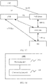
- the IAB donor may receive a downlink data packet including the third data payload, where a structure of the downlink data packet may be shown in FIG. 8 .
- the downlink data packet shown in FIG. 8 includes the third data payload and the packet header information, and the packet header information may be an IP packet header.
- Step 702 The IAB donor sends a third data packet to the IAB node.
- the third data packet includes the third data payload and a first BAP layer header, and the first BAP layer header includes the first label.
- the IAB donor may add the first BAP layer header to the downlink data packet, to obtain the third data packet.
- a structure of the third data packet may be shown in FIG. 9 .
- the third data packet includes the first BAP layer header, the third data payload, and the like.
- the IAB donor in step 700 to step 702 may be specifically the IAB donor DU, that is, the IAB donor DU may add the first label to the first BAP layer header in the third data packet.
- the IAB donor CU (which may be an IAB donor CU-CP in a specific implementation) sends the third configuration information to the IAB donor DU.
- the third configuration information may be included in an F1AP message sent by the IAB donor CU to the IAB donor DU.
- the IAB donor may generate the third configuration information, or may obtain the third configuration information from OAM
- FIG. 10 is a schematic flowchart of a data packet transmission method according to an embodiment of this application. The method includes the following step:
- Step 1000 A second IAB node receives fourth configuration information from an IAB donor.
- the second IAB node may be an access IAB node.
- the IAB donor CU may configure the fourth configuration information for the second IAB node.
- the IAB donor CU-CP may configure the fourth configuration information for the second IAB node.
- the fourth configuration information is used to configure a correspondence between a second label and second information in packet header information corresponding to a fourth data payload obtained by the second IAB node, and the second label is used to determine an egress RLC channel of the fourth data payload.
- the second information may include any one or more of the following: second differentiated service information in the packet header information, a second flow label in the packet header information, a second IP address in the packet header information, and data radio bearer information that is in the packet header information and that corresponds to the fourth data payload.
- the fourth configuration information may include any one or more of the following:
- the second IAB node determines the second label based on the second information in the uplink data packet, the data radio bearer information corresponding to the fourth data payload, the F1AP message type corresponding to the fourth data payload, or the stream identifier at the SCTP layer that carries the fourth data payload, and then sends, to a next-hop node, the uplink data packet to which the second label is added.
- the second label based on the second information in the uplink data packet, the data radio bearer information corresponding to the fourth data payload, the F1AP message type corresponding to the fourth data payload, or the stream identifier at the SCTP layer that carries the fourth data payload.
- this embodiment of this application further includes the following steps.
- Step 1001 The second IAB node obtains the fourth data payload. Specifically, the second IAB node may generate the fourth data payload, or receive the fourth data payload from a terminal device or a child node served by the second IAB node.
- Step 1002 The second IAB node determines the second label.
- the second IAB node may determine the second label based on the packet header information corresponding to the fourth data payload, the data radio bearer information corresponding to the fourth data payload, the F1AP message type corresponding to the fourth data payload, or the stream identifier at the SCTP layer that carries the fourth data payload.
- Step 1003 The second IAB node sends a fourth data packet to a parent node.
- the fourth data packet includes the fourth data payload and a second BAP layer header, and the second BAP layer header includes the second label.
- FIG. 11 is a schematic flowchart of a data packet transmission method according to an embodiment of this application. The method includes the following step:
- Step 1100 A first IAB node receives fifth configuration information from an IAB donor.
- the fifth configuration information is used to configure a correspondence between a third label and a third RLC channel identifier.
- the third label is carried in a BAP layer header of a data packet, and is used by the first IAB node to determine an egress RLC channel of the data packet.
- the third RLC channel identifier is used to identify an egress BH RLC channel (that is, a third BH RLC channel) through which the first IAB node sends a data packet, and may be an identifier of the third BH RLC channel or a logical channel identifier corresponding to the third BH RLC channel.
- the fifth configuration information may include any one or more of the following:
- configuration information configured by the IAB donor for the IAB node may include only a correspondence between an ingress RLC channel and an egress RLC channel, that is, a correspondence between the fourth RLC channel identifier and the third RLC channel identifier.
- the IAB donor CU may configure the fifth configuration information for the first IAB node.
- the IAB donor CU-CP may configure the fifth configuration information for the first IAB node.
- the first IAB node may be an intermediate IAB node.
- a data packet (the data packet may be an uplink data packet or a downlink data packet) received by the intermediate IAB node on a wireless backhaul link has carried a label. Therefore, the intermediate IAB node needs to perform bearer mapping based on the label carried in the data packet, that is, selects an egress RLC channel for the data packet to send the data packet to a next-hop node.
- the intermediate IAB node may perform bearer mapping on the received data packet based on the fifth configuration information. Descriptions are provided below in detail.
- this embodiment of this application further includes the following steps.
- Step 1101 The first IAB node obtains a data packet.
- the data packet is a data packet from a second IAB node, or the data packet is a data packet from an IAB donor.
- a backhaul adaptation protocol BAP layer header of the data packet includes the third label.
- Step 1102 The first IAB node determines the third RLC channel identifier based on the third label.
- the first IAB node when the fifth configuration information includes the third label, the ingress link identifier, the fourth RLC channel identifier, the egress link identifier, and the third RLC channel identifier, the first IAB node performs routing selection on the data packet to determine the egress link identifier, and then determines the third RLC channel identifier based on the third label in the data packet, an ingress link on which the data packet is received, and a fourth RLC channel on the ingress link on which the data packet is received. Another case is not described.
- Step 1103 The first IAB node sends the data packet through the egress RLC channel corresponding to the third RLC channel identifier.
- the first IAB node performs bearer mapping on the data packet based on the fifth configuration information.
- This solution may allow the first IAB node to perform bearer mapping more flexibly, to provide finer QoS guarantee in the IAB network.
- FIG. 12 is a schematic flowchart of a data packet transmission method according to an embodiment of this application. The method includes the following step:
- Step 1200 A second IAB node receives sixth configuration information from an IAB donor.
- the second IAB node may be an access IAB node.
- the IAB donor CU may configure the sixth configuration information for the second IAB node.
- the IAB donor CU-CP may configure the sixth configuration information for the second IAB node.
- the sixth configuration information is used to configure packet header information correspondingly added to a sixth data payload that needs to be transmitted by the second IAB node.
- the sixth data payload may be an F1 control plane (F1-C) message, that is, an F1AP message, between the second IAB node and the IAB donor (which may be specifically the IAB donor CU or the IAB donor CU-CP).
- F1-C F1 control plane
- the packet header information is a field in an IP packet header, and specifically includes differentiated service information and/or a flow label (flow label).
- the sixth configuration information specifically includes any one or more of the following content: first differentiated service information and/or a first flow label specified for a UE associated F1AP message (UE associated F1AP message) and second differentiated service information and/or a second flow label specified for a non-UE associated F1AP message (non-UE associated F1AP message).
- the sixth configuration information specifically includes any one or more of the following content: an identifier of a first terminal device, the first differentiated service information and/or the first flow label specified for the UE associated F1AP message of the first terminal device, and the second differentiated service information and/or the second flow label specified for the non-UE associated F1AP message.
- the second IAB node determines, based on an F1AP message type corresponding to the sixth data payload, differentiated service information and/or a flow label that is to be added to the IP packet header, and then sends, to a next-hop node, the uplink data packet to which the differentiated service information and/or the flow label are/is added. For details, refer to descriptions of step 1201 to step 1203.
- this embodiment of this application further includes the following steps.
- Step 1201 The second IAB node obtains the sixth data payload. Specifically, the second IAB node may generate the sixth data payload.
- Step 1202 The second IAB node determines the differentiated service information and/or the flow label corresponding to the sixth data payload.
- the second IAB node may determine, based on the F1AP message type (for example, the non-UE associated F1AP message or the UE associated F1AP message) corresponding to the sixth data payload, the differentiated service information and/or the flow label corresponding to the sixth data payload, or when the sixth data payload is the UE associated F1AP message, the second IAB node may determine, based on the identifier that is of the first terminal device and that corresponds to the sixth data payload, the differentiated service information and/or the flow label corresponding to the sixth data payload.
- the F1AP message type for example, the non-UE associated F1AP message or the UE associated F1AP message
- the sixth data payload when the sixth data payload is the non-UE associated F1AP message, the sixth data payload corresponds to the second differentiated service information and/or the second flow label, or when the sixth data payload is the UE associated F1AP message, the sixth data payload corresponds to the first differentiated service information and/or the first flow label.
- the sixth data payload when the sixth data payload is the UE associated F1AP message of the first terminal device, the sixth data payload corresponds to the first differentiated service information and/or the first flow label.
- Step 1203 The second IAB node sends a sixth data packet to a parent node.
- the sixth data packet includes the sixth data payload and an IP packet header
- the IP packet header includes the differentiated service information and/or the flow label that correspond/corresponds to the sixth data payload and that are/is determined in step 1202.
- the second IAB node may determine, based on the differentiated service information and/or the flow label included in the sixth data packet, an egress BH RLC channel used to send the sixth data packet.
- the second IAB node adds different differentiated service information and/or flow label values to different types of F1AP messages based on the sixth configuration information, so that the second IAB node can determine, based on BH RLC channels corresponding to the differentiated service information and/or the flow label values, the BH RLC channels used to send the F1AP messages, to provide differentiated QoS guarantee for the different types of F1-C messages.
- UE is connected to both a master node (Master Node, MN) and a secondary node (Secondary Node, SN).
- the MN and the SN may use a same access standard (for example, both the MN and the SN use an LTE standard or an NR standard), or may use different access standards (for example, the MN uses an LTE standard, and the SN uses an NR standard, or the MN uses an NR standard, and the SN uses an LTE standard).
- a master cell group (Master Cell Group, MCG) includes a serving cell associated with the MN, and includes at least one primary cell PCell, and optionally includes one or more secondary cells SCells.
- a secondary cell group (Secondary Cell Group, SCG) includes a serving cell associated with the SN, and includes at least one primary cell (e.g. primary secondary cell (PSCell)), and optionally includes one or more secondary cells SCells.
- An MCG link is a single-hop access link between the UE and the MN
- an SCG link is a single-hop access link between the UE and the SN.
- the UE When the UE finds that a radio link failure (Radio Link Failure, RLF) occurs on the MCG link between the UE and the MN, the UE triggers an RRC connection re-establishment process to recover the MCG link.
- RLF Radio Link Failure
- the UE does not trigger an RRC connection re-establishment process, but sends an SCG failure report (SCG failure report) to the MN by using the MCG, so that the MN triggers an SCG failure recovery process to recover the SCG link, for example, triggers an SCG change process.
- SCG failure report SCG failure report
- the UE uses a mechanism similar to an SCG failure mechanism, no longer triggers an RRC connection re-establishment process, but sends an MCG failure report (MCG failure report) by using the SCG.
- MCG failure report MCG failure report
- an IAB node can work in standalone (standalone, SA) mode or non-standalone (non-standalone, NSA) mode based on EN-DC (E-UTRAN NR Dual Connectivity).
- an MN that provides a service for the IAB node is an eNB
- an SN that provides a service for the IAB node is an IAB donor (IAB donor).
- the MN uses an LTE standard
- the SN uses an NR standard.
- an MCG link is a link between the IAB node (that is, an IAB node MT) and the MN
- an SCG link is a link between the IAB node (that is, the IAB node MT) and the SN.
- the IAB node When the IAB node detects that an RLF occurs on the SCG link between the IAB node and the IAB donor, the IAB node sends, through the MCG link, an SCG failure report to the eNB that provides a service for the IAB node, so that the eNB triggers an SCG failure recovery process to recover the SCG link.
- the IAB node needs to send one piece of RLF indication information to a child node of the IAB node, so that the child node of the IAB node performs corresponding processing.
- the child node of the IAB node receives the RLF indication information sent by the IAB node
- the child node of the IAB node sends, by using an MCG, an SCG failure report to an eNB that provides a service for the child node.
- the child node of the IAB node may be UE or another IAB node.
- the eNB that provides a service for the IAB node may be the same as or different from the eNB that provides a service for the child node of the IAB node. This is not limited in this embodiment.
- this embodiment is also applicable to an IAB multi-hop scenario.
- there may be another IAB node on a link between the IAB node and the donor node that is, a scenario in which the IAB node is connected to the donor node by using the another IAB node. Details are not described herein.
- the methods and the operations implemented by the terminal device may alternatively be implemented by a component (for example, a chip or a circuit) that may be used in the terminal device
- the methods and the operations implemented by the network device may alternatively be implemented by a component (for example, a chip or a circuit) that may be used in the network device.
- each network element includes a corresponding hardware structure and/or software module for implementing each function.
- a person skilled in the art should be easily aware that units, algorithms, and steps in the examples described with reference to the embodiments disclosed in this specification can be implemented by hardware or a combination of hardware and computer software in the present invention. Whether a function is performed by hardware or hardware driven by computer software depends on particular applications and design constraints of the technical solutions. A person skilled in the art may use different methods to implement the described functions for each particular application, but it should not be considered that the implementation goes beyond the scope of the present invention.
- FIG. 14 is a possible example block diagram of a communications apparatus according to this application.
- the apparatus 1400 may exist in a form of software or hardware.
- the apparatus 1400 may include a processing unit 1401 and a communications unit 1402.
- the communications unit 1402 may include a receiving unit and a sending unit.
- the processing unit 1401 is configured to: control and manage actions of the apparatus 1400.
- the communications unit 1402 is configured to support the apparatus 1400 in communicating with another network entity.
- the apparatus 1400 When the apparatus 1400 is configured to implement functions of the IAB donor in the method embodiment shown in FIG. 4 , the following operations are performed:
- the processing unit is configured to determine first configuration information, where the first configuration information is used to indicate a first backhaul link BH radio link control RLC channel, and the first BH RLC channel is used to transmit a control protocol data unit PDU at a backhaul adaptation protocol BAP layer.
- the communications unit is configured to send the first configuration information to an IAB node.
- the first configuration information includes a channel identifier of the first BH RLC channel; or the first configuration information includes a logical channel identifier, and a logical channel indicated by the logical channel identifier corresponds to the first BH RLC channel.
- the apparatus 1400 When the apparatus 1400 is configured to implement functions of the IAB node in the method embodiment shown in FIG. 4 , the following operations are performed:
- the processing unit is configured to determine a first backhaul link BH radio link control RLC channel used to transmit a control protocol data unit PDU at a BAP layer.
- the communications unit is configured to send the control PDU at the BAP layer to an adjacent node of the IAB node through the first BH RLC channel.
- the processing unit is specifically configured to:
- the first configuration information includes a channel identifier of the first BH RLC channel; or the first configuration information includes a logical channel identifier, and a logical channel indicated by the logical channel identifier corresponds to the first BH RLC channel.
- the apparatus 1400 When the apparatus 1400 is configured to implement functions of the IAB donor in the method embodiment shown in FIG. 5 , the following operations are performed:
- the processing unit is configured to determine second configuration information, where the second configuration information is used to indicate a second backhaul link BH radio link control RLC channel, the second BH RLC channel is used to transmit a first-type data payload, and the first-type data payload is a data payload other than an F1 user plane F1-U data payload and an F1 control plane F1-C data payload.
- the communications unit is configured to send the second configuration information to an IAB node.
- the first-type data payload includes any one of the following:
- the second configuration information includes any one or more of the following:
- processing unit is further configured to:
- the second configuration information includes identification information used to identify the second BH RLC channel, and the identification information is a channel identifier of the second BH RLC channel, or the identification information is a logical channel identifier corresponding to the second BH RLC channel.
- the apparatus 1400 When the apparatus 1400 is configured to implement functions of the IAB node in the method embodiment shown in FIG. 5 , the following operations are performed:
- the communications unit is configured to receive second configuration information from an IAB donor, where the second configuration information is used to indicate a second backhaul link BH radio link control RLC channel, the second BH RLC channel is used to transmit a first-type data payload, and the first-type data payload is a data payload other than an F1 user plane F1-U data payload and an F1 control plane F1-C data payload.
- the processing unit is configured to transmit the first-type data payload based on the second configuration information.
- the first-type data payload includes any one of the following:
- the second configuration information includes any one or more of the following:
- the second configuration information includes identification information used to identify the second BH RLC channel, and the identification information is a channel identifier of the second BH RLC channel, or the identification information is a logical channel identifier corresponding to the second BH RLC channel.
- the apparatus 1400 may further implement functions of the IAB donor in the method embodiment shown in FIG. 7 , the apparatus 1400 may further implement functions of the second IAB node in the method embodiment shown in FIG. 10 , the apparatus 1400 may further implement functions of the first IAB node in the method embodiment shown in FIG. 11 , and the apparatus 1400 may further implement functions of the second IAB node in the method embodiment shown in FIG. 12 .
- the apparatus 1400 may further implement functions of the IAB donor in the method embodiment shown in FIG. 7
- the apparatus 1400 may further implement functions of the second IAB node in the method embodiment shown in FIG. 10
- the apparatus 1400 may further implement functions of the first IAB node in the method embodiment shown in FIG. 11
- the apparatus 1400 may further implement functions of the second IAB node in the method embodiment shown in FIG. 12 .
- FIG. 15 shows an apparatus 1500 according to an embodiment of this application.
- the apparatus shown in FIG. 15 may be an implementation of a hardware circuit of the apparatus shown in FIG. 14 .
- the communications apparatus may be used in the flowchart shown above, and performs functions of the IAB node or the IAB donor in the foregoing method embodiments.
- FIG. 15 shows only main components of the communication apparatus.
- the apparatus 1500 shown in FIG. 15 includes at least one processor 1501.
- the processor 1501 may be a general-purpose central processing unit (central processing unit, CPU), a general-purpose processor, a digital signal processor (digital signal processor, DSP), an application-specific integrated circuit (application-specific integrated circuit, ASIC), a field programmable gate array (field programmable gate array, FPGA) or another programmable logic device, a transistor logic device, a hardware component, or any combination thereof.
- the processor may implement or execute various example logical blocks, modules, and circuits described with reference to content disclosed in this application.
- the processor may be a combination of processors implementing a computing function, for example, a combination of one or more microprocessors, or a combination of a DSP and a microprocessor.
- the apparatus 1500 may further include at least one memory 1502, configured to store program instructions and/or data.
- the memory 1502 is coupled to the processor 1501.
- the coupling in this embodiment of this application is indirect coupling or a communication connection between apparatuses, units, or modules for information exchange between the apparatuses, the units, or the modules, and may be in electrical, mechanical, or other forms.
- the processor 1501 may operate in collaboration with the memory 1502.
- the processor 1501 may execute the program instructions stored in the memory 1502. At least one of the at least one memory may be included in the processor.
- the apparatus 1500 may further include a communications interface 1503, configured to communicate with another device through a transmission medium, so that an apparatus in the apparatus 1500 can communicate with the another device.
- the communications interface may be a transceiver, a circuit, a bus, a module, or a communications interface of another type.
- the transceiver may be an independent receiver, an independent transmitter, a transceiver integrated with a transceiver function, or an interface circuit.
- the apparatus 1500 may further include a communications line 1504.
- the communications interface 1503, the processor 1501, and the memory 1502 may be connected to each other through the communications line 1504.
- the communications line 1504 may be a peripheral component interconnect (peripheral component interconnect, PCI for short) bus, an extended industry standard architecture (extended industry standard architecture, EISAfor short) bus, or the like.
- the communications line 1504 may be classified into an address bus, a data bus, a control bus, and the like. For ease of representation, only one thick line is used to represent the communications line in FIG. 15 , but this does not mean that there is only one bus or only one type of bus.
- the apparatus 1500 may implement functions of the IAB node or the IAB donor in the method embodiment shown in FIG. 4 , the apparatus 1500 may further implement functions of the IAB node or the IAB donor in the method embodiment shown in FIG. 5 , the apparatus 1500 may further implement functions of the IAB donor in the method embodiment shown in FIG. 7 , the apparatus 1500 may further implement functions of the second IAB node in the method embodiment shown in FIG. 10 , the apparatus 1500 may further implement functions of the first IAB node in the method embodiment shown in FIG. 11 , and the apparatus 1500 may further implement functions of the second IAB node in the method embodiment shown in FIG. 12 .
- the apparatus 1500 may implement functions of the IAB node or the IAB donor in the method embodiment shown in FIG. 4 , the apparatus 1500 may further implement functions of the IAB node or the IAB donor in the method embodiment shown in FIG. 5 , the apparatus 1500 may further implement functions of the IAB donor in the method embodiment shown in FIG. 7 , the apparatus 1500 may further implement functions of the second IAB node in the
- this application may be provided as a method, a system, or a computer program product. Therefore, this application may use a form of hardware only embodiments, software only embodiments, or embodiments with a combination of software and hardware. Moreover, this application may use a form of a computer program product that is implemented on one or more computer-usable storage media (including but not limited to a disk memory, an optical memory, and the like) that include computer-usable program code.
- a computer-usable storage media including but not limited to a disk memory, an optical memory, and the like
- These computer program instructions may be provided for a general-purpose computer, a dedicated computer, an embedded processor, or a processor of another programmable data processing device to generate a machine, so that the instructions executed by the computer or the processor of the another programmable data processing device generate an apparatus for implementing a specific function in one or more procedures in the flowcharts and/or in one or more blocks in the block diagrams.
- These computer program instructions may alternatively be stored in a computer-readable memory that can indicate a computer or another programmable data processing device to work in a specific manner, so that the instructions stored in the computer-readable memory generate an artifact that includes an instruction apparatus.
- the instruction apparatus implements a specific function in one or more procedures in the flowcharts and/or in one or more blocks in the block diagrams.
Landscapes
- Engineering & Computer Science (AREA)
- Computer Networks & Wireless Communication (AREA)
- Signal Processing (AREA)
- Computer Security & Cryptography (AREA)
- Mobile Radio Communication Systems (AREA)
- Communication Control (AREA)
Applications Claiming Priority (1)
| Application Number | Priority Date | Filing Date | Title |
|---|---|---|---|
| PCT/CN2019/109728 WO2021062803A1 (fr) | 2019-09-30 | 2019-09-30 | Procédé et dispositif de transmission de paquets de données |
Publications (2)
| Publication Number | Publication Date |
|---|---|
| EP4044543A1 true EP4044543A1 (fr) | 2022-08-17 |
| EP4044543A4 EP4044543A4 (fr) | 2022-09-21 |
Family
ID=75336766
Family Applications (1)
| Application Number | Title | Priority Date | Filing Date |
|---|---|---|---|
| EP19947563.3A Pending EP4044543A4 (fr) | 2019-09-30 | 2019-09-30 | Procédé et dispositif de transmission de paquets de données |
Country Status (6)
| Country | Link |
|---|---|
| US (1) | US12219458B2 (fr) |
| EP (1) | EP4044543A4 (fr) |
| JP (1) | JP7482997B2 (fr) |
| CN (1) | CN114467288A (fr) |
| BR (1) | BR112022005876A2 (fr) |
| WO (1) | WO2021062803A1 (fr) |
Cited By (1)
| Publication number | Priority date | Publication date | Assignee | Title |
|---|---|---|---|---|
| EP4040911A4 (fr) * | 2019-11-07 | 2022-10-26 | Huawei Technologies Co., Ltd. | Procédé et dispositif de communication |
Families Citing this family (7)
| Publication number | Priority date | Publication date | Assignee | Title |
|---|---|---|---|---|
| GB2587653B (en) * | 2019-10-03 | 2023-04-26 | Samsung Electronics Co Ltd | Flow control |
| WO2021168813A1 (fr) * | 2020-02-28 | 2021-09-02 | 华为技术有限公司 | Procédé de communication et appareil de communication |
| WO2022099509A1 (fr) * | 2020-11-11 | 2022-05-19 | Nokia Shanghai Bell Co., Ltd. | Procédés, appareils et supports lisibles par ordinateur pour contrôler des transmissions de liaison descendante dans un réseau iab (integrated access and backhaul) |
| EP4258802A4 (fr) * | 2020-12-29 | 2024-06-12 | Samsung Electronics Co., Ltd. | Dispositif et procédé de prise en charge de signalisation de plan de commande dans un système d'accès et liaison terrestre intégrés |
| US20240215103A1 (en) * | 2021-04-02 | 2024-06-27 | Lenovo (Beijing) Limited | Methods and apparatus of srb transmission using sdt |
| CN118216169A (zh) * | 2021-10-19 | 2024-06-18 | 京瓷株式会社 | 通信控制方法和中继节点 |
| CN115955688B (zh) * | 2023-03-03 | 2023-05-26 | 新华三技术有限公司 | 一种应用于5g的数据传输方法、系统、装置及电子设备 |
Family Cites Families (6)
| Publication number | Priority date | Publication date | Assignee | Title |
|---|---|---|---|---|
| US10367677B2 (en) | 2016-05-13 | 2019-07-30 | Telefonaktiebolaget Lm Ericsson (Publ) | Network architecture, methods, and devices for a wireless communications network |
| CN110035042B (zh) * | 2018-01-12 | 2020-08-07 | 华为技术有限公司 | 一种数据传输方法及装置 |
| US10972933B2 (en) | 2018-03-19 | 2021-04-06 | Qualcomm Incorporated | QoS support in wireless backhaul networks using cellular radio-access technologies |
| US10785699B2 (en) * | 2018-03-28 | 2020-09-22 | Apple Inc. | Next generation node-B (GNB) for integrated access and backhaul (IAB) relay in new radio (NR) networks |
| WO2020017941A1 (fr) * | 2018-07-20 | 2020-01-23 | Lg Electronics Inc. | Procédé et appareil de prise en charge de la détection d'encombrement de liaison dans un système de communication sans fil |
| KR20200032560A (ko) * | 2018-09-18 | 2020-03-26 | 삼성전자주식회사 | 무선 통신 시스템에서 데이터를 송수신하는 방법 및 장치 |
-
2019
- 2019-09-30 CN CN201980100956.XA patent/CN114467288A/zh active Pending
- 2019-09-30 JP JP2022519832A patent/JP7482997B2/ja active Active
- 2019-09-30 BR BR112022005876A patent/BR112022005876A2/pt unknown
- 2019-09-30 WO PCT/CN2019/109728 patent/WO2021062803A1/fr not_active Ceased
- 2019-09-30 EP EP19947563.3A patent/EP4044543A4/fr active Pending
-
2022
- 2022-03-30 US US17/708,767 patent/US12219458B2/en active Active
Cited By (2)
| Publication number | Priority date | Publication date | Assignee | Title |
|---|---|---|---|---|
| EP4040911A4 (fr) * | 2019-11-07 | 2022-10-26 | Huawei Technologies Co., Ltd. | Procédé et dispositif de communication |
| US12232103B2 (en) | 2019-11-07 | 2025-02-18 | Huawei Technologies Co., Ltd. | Communication method of transmitting a control plane message for an interface between a radio backhaul device and a radio access device through another radio access device |
Also Published As
| Publication number | Publication date |
|---|---|
| JP2022549953A (ja) | 2022-11-29 |
| US20220225209A1 (en) | 2022-07-14 |
| JP7482997B2 (ja) | 2024-05-14 |
| EP4044543A4 (fr) | 2022-09-21 |
| CN114467288A (zh) | 2022-05-10 |
| US12219458B2 (en) | 2025-02-04 |
| WO2021062803A1 (fr) | 2021-04-08 |
| BR112022005876A2 (pt) | 2022-06-21 |
Similar Documents
| Publication | Publication Date | Title |
|---|---|---|
| US12219458B2 (en) | Data packet transmission method and apparatus | |
| US11510131B2 (en) | Configuration method, data transmission method, and apparatus | |
| CN114223260B (zh) | 用于无线回程上分组转发的配置 | |
| US11102832B2 (en) | Method and wireless communication system for handling offloading of DRBs to WLAN carrier | |
| US11647561B2 (en) | Node and communication method | |
| US9883441B2 (en) | Method and apparatus to route packet flows over two transport radios | |
| US20230189091A1 (en) | Iab node configuration method and communication apparatus | |
| US9077430B2 (en) | Method, device and system for transmitting relay data | |
| CN111586890B (zh) | 一种数据传输方法及装置 | |
| EP3917272B1 (fr) | Procédés de commande, appareil et produit programme d'ordinateur pour une liaison terrestre radio | |
| CN107006022A (zh) | Lwa pdu路由方法及装置 | |
| CN106899582B (zh) | 一种LTE-Advanced Pro系统实现LWA功能的协议配置方法 | |
| US12207174B2 (en) | Communication method and related apparatus | |
| WO2020192654A1 (fr) | Procédé et appareil de configuration de porteuse de contrôle de liaison radio (rlc) | |
| CN109429267B (zh) | 数据传输方法、相关装置及系统 | |
| CN116349304A (zh) | Iab网络的rlf恢复方法、装置以及相关设备 | |
| US20210185750A1 (en) | Multi-hop data transmission method and apparatus | |
| US11470661B2 (en) | Backhaul channel management for IAB networks | |
| US12232103B2 (en) | Communication method of transmitting a control plane message for an interface between a radio backhaul device and a radio access device through another radio access device | |
| RU2803196C1 (ru) | Способ передачи пакета данных и устройство | |
| WO2022154728A1 (fr) | Procédés et nœuds de réseau pour gérer une communication |
Legal Events
| Date | Code | Title | Description |
|---|---|---|---|
| STAA | Information on the status of an ep patent application or granted ep patent |
Free format text: STATUS: THE INTERNATIONAL PUBLICATION HAS BEEN MADE |
|
| PUAI | Public reference made under article 153(3) epc to a published international application that has entered the european phase |
Free format text: ORIGINAL CODE: 0009012 |
|
| STAA | Information on the status of an ep patent application or granted ep patent |
Free format text: STATUS: REQUEST FOR EXAMINATION WAS MADE |
|
| 17P | Request for examination filed |
Effective date: 20220427 |
|
| AK | Designated contracting states |
Kind code of ref document: A1 Designated state(s): AL AT BE BG CH CY CZ DE DK EE ES FI FR GB GR HR HU IE IS IT LI LT LU LV MC MK MT NL NO PL PT RO RS SE SI SK SM TR |
|
| REG | Reference to a national code |
Ref country code: DE Ref legal event code: R079 Free format text: PREVIOUS MAIN CLASS: H04L0029060000 Ipc: H04W0040240000 |
|
| A4 | Supplementary search report drawn up and despatched |
Effective date: 20220823 |
|
| RIC1 | Information provided on ipc code assigned before grant |
Ipc: H04W 28/02 20090101ALN20220817BHEP Ipc: H04W 88/08 20090101ALN20220817BHEP Ipc: H04W 40/22 20090101ALN20220817BHEP Ipc: H04W 40/24 20090101AFI20220817BHEP |
|
| DAV | Request for validation of the european patent (deleted) | ||
| DAX | Request for extension of the european patent (deleted) | ||
| RAP3 | Party data changed (applicant data changed or rights of an application transferred) |
Owner name: HUAWEI TECHNOLOGIES CO., LTD. |
|
| STAA | Information on the status of an ep patent application or granted ep patent |
Free format text: STATUS: EXAMINATION IS IN PROGRESS |
|
| 17Q | First examination report despatched |
Effective date: 20250124 |