EP4044792B1 - Dispositif de récolte - Google Patents
Dispositif de récolte Download PDFInfo
- Publication number
- EP4044792B1 EP4044792B1 EP20812216.8A EP20812216A EP4044792B1 EP 4044792 B1 EP4044792 B1 EP 4044792B1 EP 20812216 A EP20812216 A EP 20812216A EP 4044792 B1 EP4044792 B1 EP 4044792B1
- Authority
- EP
- European Patent Office
- Prior art keywords
- harvesting device
- longitudinal axis
- rods
- harvested produce
- main body
- Prior art date
- Legal status (The legal status is an assumption and is not a legal conclusion. Google has not performed a legal analysis and makes no representation as to the accuracy of the status listed.)
- Active
Links
Images



Classifications
-
- A—HUMAN NECESSITIES
- A01—AGRICULTURE; FORESTRY; ANIMAL HUSBANDRY; HUNTING; TRAPPING; FISHING
- A01D—HARVESTING; MOWING
- A01D46/00—Picking of fruits, vegetables, hops, or the like; Devices for shaking trees or shrubs
- A01D46/30—Robotic devices for individually picking crops
-
- A—HUMAN NECESSITIES
- A01—AGRICULTURE; FORESTRY; ANIMAL HUSBANDRY; HUNTING; TRAPPING; FISHING
- A01D—HARVESTING; MOWING
- A01D46/00—Picking of fruits, vegetables, hops, or the like; Devices for shaking trees or shrubs
- A01D46/005—Picking of fruits, vegetables, hops, or the like; Devices for shaking trees or shrubs picking or shaking pneumatically
-
- A—HUMAN NECESSITIES
- A01—AGRICULTURE; FORESTRY; ANIMAL HUSBANDRY; HUNTING; TRAPPING; FISHING
- A01D—HARVESTING; MOWING
- A01D46/00—Picking of fruits, vegetables, hops, or the like; Devices for shaking trees or shrubs
- A01D46/24—Devices for picking apples or like fruit
Definitions
- the present invention relates to a harvesting device with the features according to the patent claims.
- GB 2 202 724 A is a prior art fruit picker with a body consisting of a tube, part of which is shaped into fingers which, when connected to a handle, enable the operator to pick fruit from trees.
- the fruits are protected within the tube of the fingers, which act like a slipping clutch on unripe fruits when rotated. These can be left to ripen or alternatively harvested by pinching the stem between the fingers by pushing the tool higher and then rotating.
- An adjustable finger spreader held in position by the tension of the fingers, all held by an elastic band, allows for the collection of different types and sizes of fruit.
- GB 604 435 A is a prior art device on or for attachment to a pole or the like for collecting fruit and gripping rounded objects, which includes a head carrying three substantially equally spaced and substantially equally divergent straight, rigid tines or the like , which are arranged so that they lie on a conical surface, the angle of inclination of the tines or the like to the axis of the conical surface being between 10 and 20 degrees.
- GB 521 908 A is a prior art fruit picker consisting of a hollow conical, pyramidal or similar converging element made of sheet metal, intended to grasp the fruit and remove it by a rotary movement, the lower end of such element being fitted with a sleeve or ferrule to hold a rod or a handle.
- a hollow inverted pyramidal element is at opposite diagonal angles in Divided into halves, with half connected to a sleeve to hold a rod.
- the parts are provided with side flanges at the pitch, the flanges of the part being bent upward at their lower ends to receive the lower ends of the side flanges of the fixed part and to provide a rotary connection.
- the parts are pushed apart by a spring band and adjusted relative to one another using a screw that engages in a tongue of the movable part.
- the upper edge of the pyramid-shaped parts can be provided with a V-shaped cutting opening or notch.
- GB 219 879 A is a state-of-the-art clipper equipped with spoon-shaped blades that are sharpened at the tip.
- the fruits are cut off and remain in the shell formed by the scissors or are collected in a container attached to the device.
- the shell is formed by curved claws, with the cutting edges omitted. There may be cutters for cords or wires attached to the device.
- the device includes a generally cylindrically shaped, open-topped container attached to the upper end of an elongated rod.
- a plurality of spaced apart fingers extend upwardly from the upper edge portion of the container.
- Each finger includes an enlarged base portion consisting of downwardly sloping shoulders that extend laterally outward from the side edges of the fingers to intersect with the corresponding shoulders of the next adjacent fingers.
- the edge portions of the shoulders are sharpened to form cutting edges that cleanly cut through the stem of the fruit when the edges are pressed upward against the stem, allowing the fruit to fall into the container.
- the harvesting device 1 which is suitable for picking fruits, fruits or vegetables, for example, is shown in a starting position.
- it is a harvest head or picker.
- this harvesting device particularly sensitive fruits such as. B. Strawberries of different sizes and shapes are picked up by machine and separated from the plant.
- the function of the harvesting device 1 results from the interaction of various components using different physical principles.
- the harvesting device 1 has two ends A and B.
- the first end A faces the crop and the second end B faces away from the crop, ie in particular the fruit to be harvested.
- the longitudinal axis C of the harvesting device 1 extends between the two ends A and B. Starting from the second end B of the harvesting device, the following are arranged along the longitudinal axis C in the following order: a base body 2, a guide body 3 and a suction body 4.
- the harvesting device 1 is connected to the arm of a robot in the area of the second end B or connected to the arm of a robot at the second end B, which in Figure 1 is not shown.
- the harvesting device 1 according to the invention therefore corresponds to a robot gripper.
- the base body 2 and the guide body 3 are arranged at a distance from one another along the longitudinal axis C, the distance being, for example, 40% of the distance between the two ends A and B, i.e. the length of the harvesting device 1 or the gripper according to the invention.
- a plurality of rods 5 are arranged around the longitudinal axis C, which extend from the base body 2 to the first end A. i.e. the longitudinal axis C is surrounded by several rods 5.
- a plurality of rods 5 are arranged around the longitudinal axis C, the rods 5 enclosing the longitudinal axis C in particular in a circular or ring-shaped manner.
- the harvesting device 1 according to the invention is in an initial/base position ( Figure 1 ) has the shape of a tube, in particular with a small or as small as possible diameter, which makes it much easier to reach and fix fruits to be picked in a bush, even if these fruits are partially covered by leaves.
- the rods 5 are made of a flexible or elastic material.
- the rods 5 are made of spring steel. i.e. they are thin spring steel wires.
- 16 (or more) rods 5 with a round cross section are used, each rod having a diameter of 1mm and being 120mm long.
- a large number of rods 5 is favorable, since this results in an even distribution of force on the surface of the crop and the rods 5 automatically adapt to the shape of the crop/fruit due to the spring effect, so to speak, so that Mechanical loads on the surface of the crop and thus damage are minimized.
- the rods 5 can also be made of another elastic/resilient material, for example a plastic or a composite material.
- the rods 5 extend, as described, from the base body 2 to the first end of the harvesting device 1, the rods 5 being connected to the base body 2.
- the rods 5 are glued or welded to the base body 2.
- the rods 5 are further guided through recesses/holes in the guide body 3.
- the rods 5 can also be guided by guide elements/eyelets/sleeves which are arranged on the guide body 3 (outside) (not shown in the figures).
- the recesses/holes in the guide body 3 are larger than is required for the passage of the rods 5, so that the rods 5 can be tilted by a certain angle in these recesses/holes, which, as described below, is important is.
- the diameter of the respective holes in the guide body 3 for guiding/feeding the rods 5 in or through the guide body 3 is larger than the diameter of the rods 5, insofar as the cross section of the rods 5 is round.
- the recesses/holes in the guide body 3 are, for example, twice as large as would be required for the rods 5 to pass through.
- the aforementioned considerations also apply to corresponding guide elements/eyelets/sleeves which are arranged on the guide body 3 (outside).
- the size of the recesses/holes in the guide body 3 or the guide elements/eyelets/sleeves, which are arranged on the guide body 3 (outside) depends on the thickness of the guide body 3 or on the height of the guide elements/eyelets/sleeves.
- the guide body 3 or alternatively the guide elements/eyelets/sleeves should be made as thin or low/flat as possible and made of a material that has good sliding properties, for example bronze.
- the rods 5 are connected to the base body 2 and are guided through recesses in the guide body 3 or through guide elements (outside) on the guide body 3, the rods 5 deform elastically, that is, an evasive movement of the rods 5 takes place in the guide body 3 or the guide elements/eyelets/sleeves which are arranged on the guide body 3 (outside), for example if there is a rotational movement of the guide body 3 about the longitudinal axis C relative to the non-rotatable base body 2 takes place so that the rods 5 move away from the longitudinal axis C in the area between the guide body 3 and the first end A or the distance of the rods 5 from the longitudinal axis C increases (in the area mentioned), see Figure 2 .
- the (fan) gripper i.e. the harvesting device 1
- the (fan) gripper is opened in this way.
- a rotational movement of the base body 2 about the longitudinal axis can also occur C compared to the non-rotating guide body 3, as in Figure 1 is indicated by the double arrow, or in a further alternative embodiment, an opposite rotational movement of the guide body 3 and base body 2 (possibly even taking place at the same time/simultaneously) takes place, in each case about the longitudinal axis C, in order to open the (fan) gripper, i.e the harvesting device 1.
- the rods 5 are designed or designed in such a way that they can be easily elastically (reversibly) bent/deformed, in particular due to the small cross section of the rods 5. i.e.
- the harvesting device 1 is opened and closed simply by bending/deforming/loading or bending back or allowing it to spring back/deforming/relieving the load on the rods 5. This means that no further mechanical elements such as levers or bearings are required.
- the harvesting device 1 can therefore be manufactured very simply and cost-effectively.
- the robustness of the mechanical construction increases.
- the rotational movement of the guide body 3 about the longitudinal axis C or of the base body 2 about the longitudinal axis C is preferably carried out by the guide body 3 and/or base body 2 interacting or being connected to a suitable drive, in particular to a servo motor.
- a control/drive unit also preferably includes position detection or position control with corresponding sensors, as is generally known.
- the suction body 4 is designed to be movable along the longitudinal axis C of the harvesting device 1, as shown by the double arrow in Figure 3 indicated.
- fixed crop material can be transported in the direction of the guide body 3 by means of the suction body 4.
- the suction body 4 is movable along the longitudinal axis C of the harvesting device 1 in an area between the guide body 3 and the first end A.
- the suction body 4 can also leave this area and be moved along the longitudinal axis C of the harvesting device 1 starting from the guide body 3 in the direction of the first end A and then moved beyond the first end A in order to in this way the area between the guide body 3 and the first end A, in particular to fix crops that are further away.
- the suction body 4 is in particular a bellows suction cup or a bellows suction gripper, which has a Vacuum system interacts or is connected, so that a negative pressure is generated in the suction body 4 and a first connection between the crop and the harvesting device 1 is established by sucking and fixing the crop on the suction body 4.
- the dimensions of the absorbent body 4 or the diameter of the absorbent body 4 are such that the rods 5 rest closely against the absorbent body 4 when the harvesting device 1 is closed, see Figure 1 .
- the absorbent body 4 is preferably located at the first end of the harvesting device 1 at the beginning of a harvesting/picking process, as also shown in Figure 1 shown. At the beginning of a harvesting/picking process, the absorbent body 4 can also be located (only) in the area (near) the first end of the harvesting device 1, but this is not shown, with the absorbent body 4 then being located in particular outside the area between the guide body 3 and is located at the first end A, i.e. is moved starting from the guide body 3 over the first end A in the direction of the crop.
- the suction body 4 is designed to be movable along the longitudinal axis C of the harvesting device 1 in that the suction body 4 or the head of the bellows suction device is connected to a tubular air duct 6 which is movable along the longitudinal axis C of the harvesting device 1 and which penetrates the guide body 3 and the base body 2 and lies on the longitudinal axis C of the harvesting device 1.
- the suction body 4 is connected to the vacuum system.
- a sensor for detecting the approach of the harvesting device 1 to the crop or a fruit is preferably integrated into the suction body 4. In the simplest case, a light sensor can be used for this, which is darkened by the fruit when it approaches.
- the transport of the crop fixed by means of the suction body 4 in the direction of the guide body 3, that is, in particular moving the crop for the purpose of gripping the crop in preparation for a harvest or picking, is carried out, for example, by moving the suction body 4 alone in the direction of the guide body 3, during which the base body 2, the guide body 3 and the rods 5 are not moved relative to the crop, the rods 5 of course being previously elastically deformed or as a result of a rotation of the guide body 3, the base body 2 or the guide body 3 and of the base body 2 to open the harvesting device 1 have made an evasive movement, so that the rods 5 move away from the longitudinal axis C in the area between the guide body 3 and the first end A or the distance of the rods 5 from the longitudinal axis C increases, see Figure 2 .
- a combined or joint movement of the suction body 4 takes place in the direction of the guide body 3, with the base body 2, the guide body 3 and the rods 5 also being moved relative to the crop at the same time/simultaneously, for the above-mentioned purpose of gripping the crop for a subsequent harvest.
- the crop is first picked up or enclosed between the rods 5 in the area between the guide body 3 and the first end A.
- the elastic deformation of the rods 5 is influenced in that this deformation is reversed again, so that the rods 5 in the area between the guide body 3 and the first end A move again towards the longitudinal axis C or the distance between them Rods 5 reduced in size again from the longitudinal axis C.
- a (renewed) rotational movement is initiated, namely a rotational movement in the direction/direction of rotation of the guide body 3 and/or the base body that is opposite to the previous rotational movement (required to open the harvesting device 1; complementary). 2 around the longitudinal axis C, so that the rods 5 lie on the surface of the crop, in a fan-like manner, in preparation for a harvest or a separation of the crop from a plant and grasp or fix the crop.
- Enclosing the crop with the rods 5 designed according to the invention and deformed/resilient/deformed according to the invention can replace or supplement the existing fixation of the crop by means of the suction body 4, i.e. a connection between the suction body 4 and the vacuum system can be interrupted after the rods 5 have removed the crop enclose or continue to be maintained in order to secure the crop particularly securely.
- the tips of the rods 5 are coated in an area at the first end A with a soft material 7 in order to further reduce mechanical effects on the crop or the fruit or the plant.
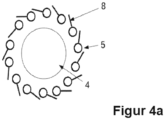
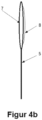
- all (or possibly only individual) bars 5 comprise cutting blades 8, as in Figure 4a and Figure 4b shown.
- the cutting blades 8 are arranged on the bars 5 in such a way that when the harvesting device 1 is not open, ie the bars 5 are not elastically deformed, the cutting blades 8 arranged on the bars 5 point in the direction of an adjacent bar 5 (please refer Figure 4a ).
- the cutting blades 8 are ready for this separation, the separation taking place in that the entire Harvesting device 1 is rotated about the longitudinal axis C, so that the cutting blades 8, ie at least one or some of the cutting blades 8, come into contact with the stem or stem of the crop and in particular as a result of a further rotation of the harvesting device 1 about the longitudinal axis C, the stem or cut through the stem.
- the cutting blades 8 are preferably embedded in the soft material 7 or combined with the soft material 7, which is arranged at the tips of the rods 5 in an area at the first end A or covers the tips of the rods 5 in this area.
- the harvesting device 1 it is also possible to use the harvesting device 1 to detect the size of the crop or the relevant fruit to be picked.
- the harvesting device 1 is opened and closed with the help of a suitable drive, comprising (integrated) position control. Since the size of the crop or fruit to be gripped is initially unknown, the setpoint for regulating the opening/closing of the harvesting device 1 according to the invention is initially (always) selected so that the harvesting device 1 closes again to the base position would. From the control signals generated by the (position) controller, information can be obtained about whether and to what extent the harvesting device 1 or the fan gripper according to the invention has enclosed the crop/fruit (change in the process of the manipulated variable). by the counterforce). A corresponding correction of the setpoint for the position control leads to an adjustment of the gripping force. This is particularly advantageous if the fruits to be picked differ greatly in size. The information about the determined fruit size can be used to pre-sort the fruits during the harvesting process.
- the size of the crop is determined depending on information regarding the angle of rotation of the rotatably moved guide body 3 and/or the rotatably moved base body 2 (for opening and closing the harvesting device 1), thereby determining the size of the crop
- the size of the crop is therefore determined by means of the harvesting device 1 depending on the angle of rotation/the angle of rotation position/angle of rotation of the guide body 3, which is rotated about the longitudinal axis C (or of the base body 2, which is rotated about the longitudinal axis C) before opening the harvesting device 1, i.e . H. the angle of rotation of the guide body 3 rotatable about the longitudinal axis C (or of the base body 2 rotatable about the longitudinal axis C) in the starting position of the harvesting device 1 and depending on the angle of rotation/the angle of rotation/angle of rotation of the guide body 3 rotatable about the longitudinal axis C (or of the rotary angle).
- the longitudinal axis C rotatably moving base body 2), which results when the rods 5 are placed on the surface of the crop (fan-like) in preparation for a harvest or a separation of the crop from a plant and grasp or fix the crop.
- the position of the crop/fruits or crop/fruit recognition is carried out with the aid of a camera 8a and an image processing system, the camera 8a being in a position along the imaginary extension of a/the first robot axis 9 is mounted, see Figure 5 .
- the harvesting device 1 according to the invention is then guided in the harvesting/picking process along the connecting line 10 between the camera 8a and the crop/fruit, depth information for the position of the crop/fruit is not required.
- This preferred arrangement of the camera 8a significantly simplifies the detection process and enables the use of inexpensive hardware.
- the number of degrees of freedom for the harvesting device 1 is reduced.
- the number of robot axes required is therefore reduced to four.
- the approach of the harvesting device 1 is determined with the help of a sensor at the tip or inside. A simple light sensor inside a pipe is suitable for this.
Landscapes
- Engineering & Computer Science (AREA)
- Robotics (AREA)
- Life Sciences & Earth Sciences (AREA)
- Environmental Sciences (AREA)
- Harvesting Machines For Specific Crops (AREA)
Claims (10)
- Dispositif de récolte (1) comprenant deux extrémités (A, B), dans lequel- la première extrémité (A) est orientée vers le produit récolté et la deuxième extrémité (B) est orientée à l'opposé du produit récolté et un axe longitudinal (C) du dispositif de récolte (1) s'étend entre les deux extrémités (A, B),- en partant de la deuxième extrémité (B), le long de l'axe longitudinal (C), un corps de base (2), un corps de guidage (3) et un corps d'aspiration (4) sont agencés,- une pluralité de barres (5) est agencée autour de l'axe longitudinal (C), lesquelles barres s'étendent du corps de base (2) jusqu'à la première extrémité (A),- le corps d'aspiration (4) est mobile le long de l'axe longitudinal (C),- les barres (5) sont reliées au corps de base (2) et sont guidées par des évidements dans le corps de guidage (3) ou par des éléments de guidage sur le corps de guidage (3),- par un mouvement de rotation du corps de guidage (3) autour de l'axe longitudinal (C) par rapport au corps de base (2) non mobile en rotation ou par un mouvement de rotation du corps de base (2) autour de l'axe longitudinal (C) par rapport au corps de guidage (3) non mobile en rotation ou par un mouvement de rotation de sens contraire du corps de guidage (3) et du corps de base (2) respectivement autour de l'axe longitudinal (C), les barres (5) se déforment élastiquement et s'éloignent de l'axe longitudinal (C) dans la zone située entre le corps de guidage (3) et la première extrémité (A),- lorsque la récolte fixée au moyen du corps d'aspiration (4) est transportée en direction du corps de guidage (3) et est ramassée entre les barres (5) dans la zone située entre le corps de guidage (3) et la première extrémité (A), par un nouveau mouvement de rotation du corps de guidage (3) autour de l'axe longitudinal (C) ou du corps de base (2) autour de l'axe longitudinal (C) ou du corps de guidage (3) et du corps de base (2) respectivement autour de l'axe longitudinal (C), la déformation élastique des barres (5) est influencée, de sorte que les barres (5) s'appliquent contre la surface du produit récolté en préparation d'une séparation du produit récolté d'une plante et entourent le produit récolté.
- Dispositif de récolte (1) selon la revendication 1, dans lequel le dispositif de récolte (1) est relié au bras d'un robot dans la zone de la deuxième extrémité (B) .
- Dispositif de récolte (1) selon la revendication 1 ou 2, dans lequel le corps de base (2) et le corps de guidage (3) sont agencés à une certaine distance l'un de l'autre le long de l'axe longitudinal (C).
- Dispositif de récolte (1) selon les revendications 1 à 3, dans lequel les barres (5) entourent l'axe longitudinal (C) selon un cercle et 16 barres (5) ou plus sont utilisées.
- Dispositif de récolte (1) selon les revendications 1 à 4, dans lequel le corps d'aspiration (4) est une ventouse à soufflet qui coopère avec un système de vide, de sorte qu'une dépression est créée dans le corps d'aspiration (4) et qu'une première liaison entre la récolte et le dispositif de récolte (1) est établie par une aspiration et une fixation de la récolte sur le corps d'aspiration (4).
- Dispositif de récolte (1) selon les revendications 1 à 5, dans lequel le corps d'aspiration (4) est réalisé mobile le long de l'axe longitudinal (C) par le fait que le corps d'aspiration (4) est relié à un canal d'air (6) tubulaire mobile le long de l'axe longitudinal (C), qui traverse le corps de guidage (3) et le corps de base (2).
- Dispositif de récolte (1) selon les revendications 1 à 6, dans lequel un capteur est intégré dans le corps d'aspiration (4) pour détecter l'approche du produit récolté par le dispositif de récolte (1).
- Dispositif de récolte (1) selon les revendications 1 à 7, dans lequel toutes les barres (5) ou certaines d'entre elles comprennent des lames de coupe (8), les lames de coupe (8) étant prêtes pour cette séparation lors d'une opération de séparation de la récolte de la plante respective qui suit l'opération de saisie de la récolte, la séparation s'effectuant par le fait que l'ensemble du dispositif de récolte (1) est entraîné en rotation autour de l'axe longitudinal (C), de sorte que les lames de coupe (8) viennent en contact avec la tige de la récolte et coupent la tige.
- Dispositif de récolte (1) selon les revendications 1 à 8, dans lequel, lors de l'utilisation du dispositif de récolte (1), la taille du produit récolté est déterminée en fonction d'informations concernant l'angle de rotation du corps de guidage (3) mobile en rotation et/ou du corps de base (2) mobile en rotation.
- Dispositif de récolte (1) selon les revendications 1 à 9, dans lequel une reconnaissance du produit récolté est effectuée à l'aide d'une caméra (8a) et d'un système de traitement d'images, la caméra (8a) étant disposée à une position le long du prolongement imaginaire d'un premier axe de robot (9), le dispositif de récolte (1) étant guidé lors du processus de récolte le long de la ligne de liaison (10) entre la caméra (8a) et le produit récolté.
Applications Claiming Priority (2)
| Application Number | Priority Date | Filing Date | Title |
|---|---|---|---|
| DE102019127586.5A DE102019127586B4 (de) | 2019-10-14 | 2019-10-14 | Erntevorrichtung |
| PCT/DE2020/100884 WO2021073688A1 (fr) | 2019-10-14 | 2020-10-13 | Dispositif de récolte |
Publications (3)
| Publication Number | Publication Date |
|---|---|
| EP4044792A1 EP4044792A1 (fr) | 2022-08-24 |
| EP4044792C0 EP4044792C0 (fr) | 2023-09-27 |
| EP4044792B1 true EP4044792B1 (fr) | 2023-09-27 |
Family
ID=73597736
Family Applications (1)
| Application Number | Title | Priority Date | Filing Date |
|---|---|---|---|
| EP20812216.8A Active EP4044792B1 (fr) | 2019-10-14 | 2020-10-13 | Dispositif de récolte |
Country Status (3)
| Country | Link |
|---|---|
| EP (1) | EP4044792B1 (fr) |
| DE (1) | DE102019127586B4 (fr) |
| WO (1) | WO2021073688A1 (fr) |
Families Citing this family (2)
| Publication number | Priority date | Publication date | Assignee | Title |
|---|---|---|---|---|
| DE102022132304A1 (de) | 2022-12-06 | 2024-06-06 | Iav Gmbh Ingenieurgesellschaft Auto Und Verkehr | Ernteverfahren und -vorrichtung |
| CN116058168B (zh) * | 2023-02-10 | 2024-05-10 | 西北农林科技大学 | 一种气吸推拉式枸杞采摘装置 |
Family Cites Families (4)
| Publication number | Priority date | Publication date | Assignee | Title |
|---|---|---|---|---|
| GB2202724A (en) | 1987-03-03 | 1988-10-05 | David Rowland Morgan Jones | Fruit pickers |
| US5544474A (en) | 1995-02-21 | 1996-08-13 | Finkelstein; Zvi | System for harvesting crop items and crop harvesting tools used therewith |
| JP6648653B2 (ja) | 2016-08-22 | 2020-02-14 | 株式会社デンソー | ロボットハンド |
| CN107711078A (zh) * | 2017-10-12 | 2018-02-23 | 谷新运 | 番茄吸附夹持同步采摘末端执行器及相应采摘机构和方法 |
-
2019
- 2019-10-14 DE DE102019127586.5A patent/DE102019127586B4/de active Active
-
2020
- 2020-10-13 EP EP20812216.8A patent/EP4044792B1/fr active Active
- 2020-10-13 WO PCT/DE2020/100884 patent/WO2021073688A1/fr not_active Ceased
Also Published As
| Publication number | Publication date |
|---|---|
| EP4044792A1 (fr) | 2022-08-24 |
| DE102019127586A1 (de) | 2021-04-15 |
| WO2021073688A1 (fr) | 2021-04-22 |
| EP4044792C0 (fr) | 2023-09-27 |
| DE102019127586B4 (de) | 2021-09-23 |
Similar Documents
| Publication | Publication Date | Title |
|---|---|---|
| DE69636220T2 (de) | Endoskopisches biopsieinstrument mit verbesserter beisswirkung | |
| EP1417877B1 (fr) | Rouleau de cueillette | |
| WO2022038057A1 (fr) | Système robotique et robot mobile pour cueillir des fruits d'une plante pourvus d'une tige | |
| EP1106048B1 (fr) | Dispositif d'introduction et de cueillage d'un dispositif de chargement de récoltes | |
| EP2422610B1 (fr) | Dispositif et procédé destinés à la cueillette de plantes à fleurs | |
| EP1657975B1 (fr) | Dispositif d'effeuillage, notamment pour la vigne | |
| WO2014198598A1 (fr) | Dispositif de récolte | |
| EP2266384B1 (fr) | Dispositif de sarclage pour plantes aquatiques et bateau de sarclage doté d'un tel dispositif | |
| DE102019127586B4 (de) | Erntevorrichtung | |
| WO2014198599A1 (fr) | Moissonneuse pour moissonner des plantes a tiges | |
| DE3422820A1 (de) | Geraet zum ernten von fruechten | |
| DE102021110259B3 (de) | Vorrichtung zum Greifen und Schneiden von Erntegut | |
| DE3700970A1 (de) | Vorrichtung zum ernten von baumobst | |
| DE19641807A1 (de) | Obstpflücker mit Drehkranz | |
| DE102024108134B4 (de) | Erntevorrichtung und Ernteverfahren für Ernteroboter | |
| DE29815318U1 (de) | Obstpflücker | |
| DE19719095A1 (de) | Obstpflücker für die Ernte unterschiedlich großer Früchte | |
| DE202018004029U1 (de) | Schermesser-Anordnung zum Gartenbau | |
| EP1591047B1 (fr) | Pince pour enlever des parts indésirable ou immangeable de fruits ou légumes | |
| DE291741C (fr) | ||
| DE102007010550A1 (de) | Vorrichtung und Verfahren zum Schälen von länglichem Gemüse | |
| DE2446377A1 (de) | Kleinobstpfluecker | |
| DE2457452C3 (de) | Erntemaschine für Mais oder ähnliche Stengelpflanzen | |
| DE4329447C2 (de) | Handwerkszeug zum einhändigen Entfernen von Unkraut | |
| DE923224C (de) | Verfahren und Vorrichtung zum Vermeiden einer Anstauung von Maehgut bei Motorgrasmaehern |
Legal Events
| Date | Code | Title | Description |
|---|---|---|---|
| STAA | Information on the status of an ep patent application or granted ep patent |
Free format text: STATUS: UNKNOWN |
|
| STAA | Information on the status of an ep patent application or granted ep patent |
Free format text: STATUS: THE INTERNATIONAL PUBLICATION HAS BEEN MADE |
|
| PUAI | Public reference made under article 153(3) epc to a published international application that has entered the european phase |
Free format text: ORIGINAL CODE: 0009012 |
|
| STAA | Information on the status of an ep patent application or granted ep patent |
Free format text: STATUS: REQUEST FOR EXAMINATION WAS MADE |
|
| 17P | Request for examination filed |
Effective date: 20220512 |
|
| AK | Designated contracting states |
Kind code of ref document: A1 Designated state(s): AL AT BE BG CH CY CZ DE DK EE ES FI FR GB GR HR HU IE IS IT LI LT LU LV MC MK MT NL NO PL PT RO RS SE SI SK SM TR |
|
| DAV | Request for validation of the european patent (deleted) | ||
| DAX | Request for extension of the european patent (deleted) | ||
| GRAP | Despatch of communication of intention to grant a patent |
Free format text: ORIGINAL CODE: EPIDOSNIGR1 |
|
| STAA | Information on the status of an ep patent application or granted ep patent |
Free format text: STATUS: GRANT OF PATENT IS INTENDED |
|
| INTG | Intention to grant announced |
Effective date: 20230705 |
|
| GRAS | Grant fee paid |
Free format text: ORIGINAL CODE: EPIDOSNIGR3 |
|
| GRAA | (expected) grant |
Free format text: ORIGINAL CODE: 0009210 |
|
| STAA | Information on the status of an ep patent application or granted ep patent |
Free format text: STATUS: THE PATENT HAS BEEN GRANTED |
|
| AK | Designated contracting states |
Kind code of ref document: B1 Designated state(s): AL AT BE BG CH CY CZ DE DK EE ES FI FR GB GR HR HU IE IS IT LI LT LU LV MC MK MT NL NO PL PT RO RS SE SI SK SM TR |
|
| REG | Reference to a national code |
Ref country code: GB Ref legal event code: FG4D Free format text: NOT ENGLISH |
|
| REG | Reference to a national code |
Ref country code: CH Ref legal event code: EP |
|
| REG | Reference to a national code |
Ref country code: DE Ref legal event code: R096 Ref document number: 502020005448 Country of ref document: DE |
|
| REG | Reference to a national code |
Ref country code: IE Ref legal event code: FG4D Free format text: LANGUAGE OF EP DOCUMENT: GERMAN |
|
| U01 | Request for unitary effect filed |
Effective date: 20231020 |
|
| U07 | Unitary effect registered |
Designated state(s): AT BE BG DE DK EE FI FR IT LT LU LV MT NL PT SE SI Effective date: 20231027 |
|
| U20 | Renewal fee for the european patent with unitary effect paid |
Year of fee payment: 4 Effective date: 20231031 |
|
| PG25 | Lapsed in a contracting state [announced via postgrant information from national office to epo] |
Ref country code: GR Free format text: LAPSE BECAUSE OF FAILURE TO SUBMIT A TRANSLATION OF THE DESCRIPTION OR TO PAY THE FEE WITHIN THE PRESCRIBED TIME-LIMIT Effective date: 20231228 |
|
| PG25 | Lapsed in a contracting state [announced via postgrant information from national office to epo] |
Ref country code: RS Free format text: LAPSE BECAUSE OF FAILURE TO SUBMIT A TRANSLATION OF THE DESCRIPTION OR TO PAY THE FEE WITHIN THE PRESCRIBED TIME-LIMIT Effective date: 20230927 Ref country code: NO Free format text: LAPSE BECAUSE OF FAILURE TO SUBMIT A TRANSLATION OF THE DESCRIPTION OR TO PAY THE FEE WITHIN THE PRESCRIBED TIME-LIMIT Effective date: 20231227 Ref country code: HR Free format text: LAPSE BECAUSE OF FAILURE TO SUBMIT A TRANSLATION OF THE DESCRIPTION OR TO PAY THE FEE WITHIN THE PRESCRIBED TIME-LIMIT Effective date: 20230927 Ref country code: GR Free format text: LAPSE BECAUSE OF FAILURE TO SUBMIT A TRANSLATION OF THE DESCRIPTION OR TO PAY THE FEE WITHIN THE PRESCRIBED TIME-LIMIT Effective date: 20231228 |
|
| PG25 | Lapsed in a contracting state [announced via postgrant information from national office to epo] |
Ref country code: IS Free format text: LAPSE BECAUSE OF FAILURE TO SUBMIT A TRANSLATION OF THE DESCRIPTION OR TO PAY THE FEE WITHIN THE PRESCRIBED TIME-LIMIT Effective date: 20240127 |
|
| PG25 | Lapsed in a contracting state [announced via postgrant information from national office to epo] |
Ref country code: ES Free format text: LAPSE BECAUSE OF FAILURE TO SUBMIT A TRANSLATION OF THE DESCRIPTION OR TO PAY THE FEE WITHIN THE PRESCRIBED TIME-LIMIT Effective date: 20230927 |
|
| PG25 | Lapsed in a contracting state [announced via postgrant information from national office to epo] |
Ref country code: SM Free format text: LAPSE BECAUSE OF FAILURE TO SUBMIT A TRANSLATION OF THE DESCRIPTION OR TO PAY THE FEE WITHIN THE PRESCRIBED TIME-LIMIT Effective date: 20230927 Ref country code: RO Free format text: LAPSE BECAUSE OF FAILURE TO SUBMIT A TRANSLATION OF THE DESCRIPTION OR TO PAY THE FEE WITHIN THE PRESCRIBED TIME-LIMIT Effective date: 20230927 Ref country code: IS Free format text: LAPSE BECAUSE OF FAILURE TO SUBMIT A TRANSLATION OF THE DESCRIPTION OR TO PAY THE FEE WITHIN THE PRESCRIBED TIME-LIMIT Effective date: 20240127 Ref country code: ES Free format text: LAPSE BECAUSE OF FAILURE TO SUBMIT A TRANSLATION OF THE DESCRIPTION OR TO PAY THE FEE WITHIN THE PRESCRIBED TIME-LIMIT Effective date: 20230927 Ref country code: CZ Free format text: LAPSE BECAUSE OF FAILURE TO SUBMIT A TRANSLATION OF THE DESCRIPTION OR TO PAY THE FEE WITHIN THE PRESCRIBED TIME-LIMIT Effective date: 20230927 Ref country code: SK Free format text: LAPSE BECAUSE OF FAILURE TO SUBMIT A TRANSLATION OF THE DESCRIPTION OR TO PAY THE FEE WITHIN THE PRESCRIBED TIME-LIMIT Effective date: 20230927 |
|
| PG25 | Lapsed in a contracting state [announced via postgrant information from national office to epo] |
Ref country code: PL Free format text: LAPSE BECAUSE OF FAILURE TO SUBMIT A TRANSLATION OF THE DESCRIPTION OR TO PAY THE FEE WITHIN THE PRESCRIBED TIME-LIMIT Effective date: 20230927 |
|
| REG | Reference to a national code |
Ref country code: CH Ref legal event code: PL |
|
| REG | Reference to a national code |
Ref country code: DE Ref legal event code: R097 Ref document number: 502020005448 Country of ref document: DE |
|
| PG25 | Lapsed in a contracting state [announced via postgrant information from national office to epo] |
Ref country code: MC Free format text: LAPSE BECAUSE OF FAILURE TO SUBMIT A TRANSLATION OF THE DESCRIPTION OR TO PAY THE FEE WITHIN THE PRESCRIBED TIME-LIMIT Effective date: 20230927 |
|
| PG25 | Lapsed in a contracting state [announced via postgrant information from national office to epo] |
Ref country code: CH Free format text: LAPSE BECAUSE OF NON-PAYMENT OF DUE FEES Effective date: 20231031 |
|
| PG25 | Lapsed in a contracting state [announced via postgrant information from national office to epo] |
Ref country code: MC Free format text: LAPSE BECAUSE OF FAILURE TO SUBMIT A TRANSLATION OF THE DESCRIPTION OR TO PAY THE FEE WITHIN THE PRESCRIBED TIME-LIMIT Effective date: 20230927 Ref country code: CH Free format text: LAPSE BECAUSE OF NON-PAYMENT OF DUE FEES Effective date: 20231031 |
|
| PLBE | No opposition filed within time limit |
Free format text: ORIGINAL CODE: 0009261 |
|
| STAA | Information on the status of an ep patent application or granted ep patent |
Free format text: STATUS: NO OPPOSITION FILED WITHIN TIME LIMIT |
|
| 26N | No opposition filed |
Effective date: 20240628 |
|
| PG25 | Lapsed in a contracting state [announced via postgrant information from national office to epo] |
Ref country code: IE Free format text: LAPSE BECAUSE OF NON-PAYMENT OF DUE FEES Effective date: 20231013 |
|
| PG25 | Lapsed in a contracting state [announced via postgrant information from national office to epo] |
Ref country code: IE Free format text: LAPSE BECAUSE OF NON-PAYMENT OF DUE FEES Effective date: 20231013 |
|
| U20 | Renewal fee for the european patent with unitary effect paid |
Year of fee payment: 5 Effective date: 20241031 |
|
| PG25 | Lapsed in a contracting state [announced via postgrant information from national office to epo] |
Ref country code: CY Free format text: LAPSE BECAUSE OF FAILURE TO SUBMIT A TRANSLATION OF THE DESCRIPTION OR TO PAY THE FEE WITHIN THE PRESCRIBED TIME-LIMIT; INVALID AB INITIO Effective date: 20201013 |
|
| PG25 | Lapsed in a contracting state [announced via postgrant information from national office to epo] |
Ref country code: HU Free format text: LAPSE BECAUSE OF FAILURE TO SUBMIT A TRANSLATION OF THE DESCRIPTION OR TO PAY THE FEE WITHIN THE PRESCRIBED TIME-LIMIT; INVALID AB INITIO Effective date: 20201013 |
|
| U1N | Appointed representative for the unitary patent procedure changed after the registration of the unitary effect |
Representative=s name: WANZEK, JAN; DE |
|
| U20 | Renewal fee for the european patent with unitary effect paid |
Year of fee payment: 6 Effective date: 20250919 |
|
| PG25 | Lapsed in a contracting state [announced via postgrant information from national office to epo] |
Ref country code: TR Free format text: LAPSE BECAUSE OF FAILURE TO SUBMIT A TRANSLATION OF THE DESCRIPTION OR TO PAY THE FEE WITHIN THE PRESCRIBED TIME-LIMIT Effective date: 20230927 |
|
| PGFP | Annual fee paid to national office [announced via postgrant information from national office to epo] |
Ref country code: GB Payment date: 20251024 Year of fee payment: 6 |