EP4044889B1 - Porte-récipient verrouillable - Google Patents
Porte-récipient verrouillable Download PDFInfo
- Publication number
- EP4044889B1 EP4044889B1 EP20793487.8A EP20793487A EP4044889B1 EP 4044889 B1 EP4044889 B1 EP 4044889B1 EP 20793487 A EP20793487 A EP 20793487A EP 4044889 B1 EP4044889 B1 EP 4044889B1
- Authority
- EP
- European Patent Office
- Prior art keywords
- holder
- receptacle
- locking
- upper portion
- hole
- Prior art date
- Legal status (The legal status is an assumption and is not a legal conclusion. Google has not performed a legal analysis and makes no representation as to the accuracy of the status listed.)
- Active
Links
Images


Classifications
-
- A—HUMAN NECESSITIES
- A47—FURNITURE; DOMESTIC ARTICLES OR APPLIANCES; COFFEE MILLS; SPICE MILLS; SUCTION CLEANERS IN GENERAL
- A47K—SANITARY EQUIPMENT; ACCESSORIES THEREFOR, e.g. TOILET ACCESSORIES
- A47K5/00—Holders or dispensers for soap, toothpaste or the like
- A47K5/06—Dispensers for soap
- A47K5/12—Dispensers for soap for liquid or pasty soap
-
- F—MECHANICAL ENGINEERING; LIGHTING; HEATING; WEAPONS; BLASTING
- F16—ENGINEERING ELEMENTS AND UNITS; GENERAL MEASURES FOR PRODUCING AND MAINTAINING EFFECTIVE FUNCTIONING OF MACHINES OR INSTALLATIONS; THERMAL INSULATION IN GENERAL
- F16M—FRAMES, CASINGS OR BEDS OF ENGINES, MACHINES OR APPARATUS, NOT SPECIFIC TO ENGINES, MACHINES OR APPARATUS PROVIDED FOR ELSEWHERE; STANDS; SUPPORTS
- F16M13/00—Other supports for positioning apparatus or articles; Means for steadying hand-held apparatus or articles
- F16M13/02—Other supports for positioning apparatus or articles; Means for steadying hand-held apparatus or articles for supporting on, or attaching to, an object, e.g. tree, gate, window-frame, cycle
-
- A—HUMAN NECESSITIES
- A47—FURNITURE; DOMESTIC ARTICLES OR APPLIANCES; COFFEE MILLS; SPICE MILLS; SUCTION CLEANERS IN GENERAL
- A47K—SANITARY EQUIPMENT; ACCESSORIES THEREFOR, e.g. TOILET ACCESSORIES
- A47K2201/00—Details of connections of bathroom accessories, e.g. fixing soap or towel holder to a wall
- A47K2201/02—Connections to a wall mounted support
- A47K2201/025—Connections to a wall mounted support with resilient locking device
-
- A—HUMAN NECESSITIES
- A47—FURNITURE; DOMESTIC ARTICLES OR APPLIANCES; COFFEE MILLS; SPICE MILLS; SUCTION CLEANERS IN GENERAL
- A47K—SANITARY EQUIPMENT; ACCESSORIES THEREFOR, e.g. TOILET ACCESSORIES
- A47K5/00—Holders or dispensers for soap, toothpaste or the like
- A47K5/06—Dispensers for soap
- A47K5/12—Dispensers for soap for liquid or pasty soap
- A47K5/1202—Dispensers for soap for liquid or pasty soap dispensing dosed volume
- A47K5/1204—Dispensers for soap for liquid or pasty soap dispensing dosed volume by means of a rigid dispensing chamber and pistons
- A47K5/1205—Dispensing from the top of the dispenser with a vertical piston
Definitions
- the present disclosure relates to a receptacle holder.
- a lockable receptacle holder for a dispensing receptacle for dispensing liquid or creamy hygiene products such as soap, shampoo or lotion hand sanitizer
- US2011/0101196 shows a holder for a dispensing bottle that is provided with a collar plate that is provided with an opening for receiving the throat of a soap dispenser.
- the collar plate is guided in two rods that extend from a wall support so that the collar plate may be brought from an inward position in which the collar plate may be locked to an outward position in which the throat of a dispenser bottle may be inserted into the opening of the collar plate.
- a further holder for a dispenser bottle is shown in SE 540307 C2 .
- the collar plate is attached to the bottle support by screws. Replacement of the dispenser bottle requires removal of the screws and is therefore time consuming.
- a further object is to provide a receptacle holder which provides a lockable receptacle holder which provides high resistance to unauthorized removal of a receptacle.
- a further object of the present disclosure is to provide a lockable receptacle holder which may be manufactured at low cost.
- a lockable receptacle holder 10 comprising a holder base portion 20 configured to support the bottom 5 of a receptacle 1; a holder upper portion 30 and an elongated holder back portion 40 extending between the holder base portion 20 and the holder upper portion 30, and further comprising:
- the lockable receptacle holder is tamper resistant and allows for secure holding of receptacle.
- the hook-shaped confining member may easily be unlocked by inserting a purposely dimensioned tool into the through hole to apply a force F unto the locking portion. Subsequently the confining member is pivoted to the side thereby allowing house-keeping personnel to easily remove the receptacle for exchange or refilling. Removal and replacement of the receptacle is easy, demands no tricky handling of the receptacle and may be performed in little time.
- the receptacle holder comprises few parts and is easy to assemble. It is also easy to clean and durable. Cyclic tests have shown that the components of the receptacle holder maintain structural integrity over 7000 cycles at 9 kg pressure.
- the holder upper portion 30 of the he receptacle holder 10 may comprises an arcuate front portion 31 for receiving a portion of a neck 2 or shoulder 3 of a receptacle 1.
- the arcuate front portion provides a secure support for the receptacle during operation of the confining member.
- the hook-shaped front portion 51 of the confining member 50 may be rounded to form an at least partially closed circular space C with the front end 31 of the holder upper portion 30.
- the through hole 32 may be configured to receive an end portion 8 of a tool 7 wherein the cross-sectional shape of the through hole 32 and the end portion 8 of the tool 7 are configured such that end portion 8 of the tool 7 may pass through the through hole 32. This provides the possibility to customize the through hole so that the locking portion only may be accessed by special tools. Thus, unauthorized opening of the receptacle holder may be prevented or made difficult.
- the one of the holder upper portion 30 and the confining member 50 to which the locking member 60 is attached may comprise a receiving opening 53 for receiving the locking portion 61 of the locking member 60 when the locking portion 61 is brought out of the through hole 32.
- This allows for usage of a flat and thin locking portion, which in turn provides for a compact and tamper resistant receptacle holder.
- the locking portion 61 may thereby be elongate, flat and provided with an upright edge 62 to be received in the through hole 32.
- the locking portion is a part of a locking member 60 in the form of an integral piece of resilient steel strip.
- a particularly compact and tamper resistant the receptacle holder 10 is provided when he confining member 50 and the locking member 60 and the holder upper portion 30 are superimposed and the through hole 32 and the locking portion 61 and the receiving opening 53 are aligned so that the locking portion 61 of the locking member 60 may be pushed into the receiving opening 53 by an end portion 8 of a tool 7 that is inserted through the other opening 33, 34 of the through hole 32.
- Such a receptacle holder may be realized in that the locking member 60 is arranged underneath the holder upper portion 30 and the confining member 50 is arranged underneath the locking member 60 and wherein through hole 32 extends between an upper opening 33 on an upper side 35 and a lower opening 34 on a lower side 36 of the of the holder upper portion 30.
- the receptacle holder according to the present disclosure will now be described more fully hereinafter.
- the receptacle holder according to the present disclosure may however be embodied in many different forms and should not be construed as limited to the embodiments set forth herein. Rather, these embodiments are provided by way of example so that this disclosure will be thorough and complete, and will fully convey the scope of the present disclosure to those persons skilled in the art. Same reference numbers refer to same elements throughout the description.
- a “receptacle” or “container” is configured to hold liquid, semi-liquid, creamy or paste-formed substances.
- a receptacle is a bottle or a jar and has a neck, with a mouth, a shoulder, a body and a bottom.
- the receptacle may comprise a dispenser which is inserted into the mouth of the receptacle.
- the dispenser allows a user to pump out the content of the dispenser.
- the receptacle may is such case be denominated "dispenser receptacle”.
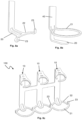
- Figure 6 shows a receptacle 1 in the form of a bottle with a dispenser 6.
- the receptacle has a neck 2, a shoulder 3, a body 4 and bottom 5.
- the receptacle holder may be realized in different sizes and dimensions to fit receptacles of varying shape, size and dimension.
- the receptacle holder in the following is described with reference to a receptacle or parts thereof, it is appreciated that the receptacle holder is dimensioned in view of that receptacle.
- any references to directions such as “upright”, “upwards”, “downwards” or “lateral” are in relation to a vertical orientation of the receptacle holder in which the holder base is below the holder upper portion.
- FIG. 1 shows an exploded view of a lockable receptacle holder 10 according to the present disclosure.
- the receptacle holder 10 comprises an elongated holder back portion 40 which may be configured to be attached to a structure such as a wall (not shown). Attachment of the holder back portion 40 to the structure may for example be achieved by double sided adhesive tape or by screws (not shown) through the openings 41.
- the holder back portion 40 extends between a holder base portion 20 and a holder upper portion 30.
- the holder base portion 20 may extend from one end of the holder back portion 20.
- the holder upper portion 30 extends opposite to the holder upper portion 30.
- the holder base portion 20 is configured to support the bottom 5 of a receptacle (not shown). In figure 1 the holder base portion 20 therefore extends approximately perpendicular from the holder back portion 40 and has a width and a length sufficient to support the bottom 5 of a receptacle 1.
- the holder upper portion 30 may extend from a second end of the holder back portion 40.
- the holder upper portion 30 may thereby extend approximately parallel with the holder base portion 20.
- the front portion 31 of the holder upper portion 30 points away from the holder back portion 40.
- the distance between the holder upper portion 30 and the holder base portion 20 may be selected such that the front end 31 of the holder upper portion faces the neck or shoulder of a receptacle that is supported on the holder base portion 20.
- the front end 31 of the holder upper portion may 30 be configured to receive a portion of the neck or shoulder of a receptacle that is supported on the holder base portion 20.
- the front end 31 of the holder upper portion 30 is arcuate, i.e.
- the holder upper portion 30 comprises a through hole 32 that extends between an upper opening 33 on the upper side 35 of the holder upper portion 30 and a lower opening 34 on the lower side 36 of the holder upper portion.
- the through hole 32 is dimensioned such that a locking portion 61 of a locking member 60 may be received through the lower opening 34 and such that at least the end portion 8 of a tool 7 may be inserted through the upper opening 33.
- the cross-section of the end portion 8 of the tool 7 may thereby have the same or smaller dimensions as cross-section of the through hole 32.
- the cross-sectional shape of the end portion 8 of the tool 7 and/or the tip 8 of the cross-sectional shape of the through hole may be same or similar.
- the through-hole 32 may be of rectangular cross-section and the end portion of the tool 7 may also be of rectangular cross-section.
- the length of the end portion 8 of the tool 7 is selected such that the end portion 8 extends through or flush with the lower opening 34 of the through hole.
- a shaft opening 38 for a pivot shaft 70 is provided in the rear portion 37 of the holder upper portion 30.
- the rear portion 37 is located between the through hole 32 in the holder upper portion 30 and the holder back portion 40.
- the receptacle holder 10 further comprises a confining member 50 which has a hook-shaped front portion 51 and a rear portion 52 which may be rectangular.
- the hook-shaped front portion 51 has a front end 57, i.e. a free front end 57.
- the hook-shaped front portion 51 is rounded, however it may also have other configuration such as triangular- or rectangular hook-shape.
- the confining member 50 is pivotally attached to the holder upper portion 30. The confining member may thereby pivot relative the holder upper portion 30 in a plane that is parallel to the width and length extension of the holder upper portion 30.
- the confining member 50 may thereby be pivotally attached to a pivot shaft 70 that extends through a shaft opening 54 in the rear portion 52 of the confining member 50 and the shaft opening 38 in the holder upper portion 30.
- the confining member 50 comprises a receiving opening 53 that is provided in the rear portion 52 of the confining member 50.
- the receiving opening 53 is provided between the shaft opening 54 and the hook-shaped front portion 51 of the confining member 50.
- the receiving opening 53 may be a through-hole or a recess, and is configured to receive a locking portion 61 of a locking member 60.
- the locking member 60 comprises a locking portion 61 and a rear portion 66 from which the locking portion 61 may extend.
- the locking portion 61 is configured to extend into the through hole 32 in the holder upper portion 30.
- the locking portion 61 may therefore be elongated and have an upright edge 62. That is, directed in direction away from the upper surface 69 of the locking member 60.
- the locking portion 61 is a flat.
- the locking portion 61 may have other configuration, for example rod-shaped. It is also possible to divide the locking portion 61 in to two locking portion halves (not shown).
- the locking member 60 is configured to be attached to the rear end of the confining member 50.
- the rear portion 66 of the locking member 60 may therefore have attachment means 63 in the form of parallel flanges that may be inserted into corresponding openings 58, such as grooves in the confining member 50.
- the locking member 60 may glued or welded to the confining member 50.
- the locking portion is resilient.
- the locking member 60 or at least the locking portion 61 is manufactured from resilient material such resilient steel strip such as spring steel.
- plastic material such as polypropylene.
- the locking member 60 may be arranged such that the locking portion 61 extends over the receiving opening 53 in the confining member 50.
- the rear portion 67 of the locking member 60 may comprise an opening 54 for the pivot shaft 70.
- the pivot shaft may be a press pin that is riveted into the holder upper portion 30.
- the end of the pivot shaft may be secured by rivet locking collar or by a nut and washer (not shown).
- the confining member 50 and the locking member 60 and the holder upper portion are superimposed and the through hole 32 and the locking portion 61 and the receiving opening 53 are aligned so that the locking portion 61 of the locking member 60 may be pushed into the receiving opening 53 by a tool 7 inserted through the upper opening 33 of the through hole 32.
- the locking member 60 is arranged underneath the holder upper portion 30 and the confining member 50 is arranged underneath the locking member.
- Figure 2a shows the assembled receptacle holder 10 in a position A in which the front portion 31 of the holder upper portion 30 and the hook-shaped front portion 51 of the confining member 50 limits a partially closed space C which is configured to confine the neck or shoulder of a receptacle (not shown in figure 2 ).
- Confine is meant that any opening between the front portion 31 of the holder upper portion 30 and the end 56 of the hook-shaped front portion 51 of the confining member 50 is too small to allow passage of a neck or shoulder of a receptacle.
- Figure 5 shows a cross-sectional view taken along line X - X in figure 2a .
- FIG. 2b shows the locking portion 61 extending over, but not beyond, the receiving opening 53 in the confining member 50.
- Figure 3a shows the tool 7 inserted into the upper opening 33 of the through opening 32.
- the tip 8 of the tool 7 thereby exerts a force F onto the upright edge 62 of the locking portion 61 and presses the locking portion 61 downwards into the receiving opening 53 (see figure 3b ).
- the confining member 50 is released to pivot relative the holder upper portion 30.
- the holder upper portion 30, the locking member 60 and the confining member 50 are superimposed with essentially no gap between them.
- the tool 7 may therefore be configured such that the end portion 8 thereof merely extend through the through hole 32. This will suffice to force the upright edge 62 of the locking portion 60 into the receiving opening 53 so that the upright edge 62 is flush with the upper surface 55 of the confining member.
- the confining member 50 will thereby be released to pivot.
- the holder upper portion 30 and the confining member 50 may be superimposed with a gap between them (not shown).
- the tip 7 of the tool 6 may be elongated to extend through the through hole 32 and through the gap between the holder upper portion 30 and the confining member 50 in order to force the edge 62 of the locking portion 61 out of the through hole and into the receiving opening 53.
- the holder upper portion 30 and the confining member 50 superimposed with a gap that is wide enough to accommodate the edge 62 of the locking portion. In that case the receiving opening 53 in the confining member 50 may be omitted (not shown).
- Figure 4a shows the receptacle holder 10 in a situation where the confining member 50 is pivoted relative the holder upper portion 30 to a release position B.
- the end 56 of the hook-shaped front portion 52 is spaced apart from the front portion 31 of the holder upper portion 30 such that an opening D is formed between the end 56 of the hook-shaped front portion 52 and the front portion 31 of the holder upper portion 30.
- the opening D is sufficiently large to allow removal of a receptacle (not shown) from the receptacle holder.
- the opening D is sufficiently large to allow passage of the neck or shoulder of the receptacle.
- the upright edge 62 of the locking portion is in sliding contact with the lower surface 36 of the holder upper portion 30 during pivoting from the locked position A to the release position B.
- the rear portion 52 of the confining member 50 may be arranged such that it hits the holder back portion 41 when the confining member 50 is in the release portion B which prevents further pivoting of the confining member 50. This is favorable because the locking portion 61 may be kept in contact with the lower side of the holder upper portion which in turn may prevent damage of the locking portion when the confining member is pivoted towards the closed position A.
- a receptacle 1 may be inserted and locked into the receptacle holder 10 by performing the steps described above in reversed order.
- the receptacle holder 10 has hereinabove been described in an embodiment in which the holder upper portion 30 comprises the through hole 32 and the confining member 50 comprises the receiving opening 53 and wherein the locking member 60 is attached to the confining member 50.
- the confining member 50 is arranged underneath the holder upper portion 30.
- the confining member 50 is arranged above the holder upper portion 30.
- Figure 9 shows an alternative in which the confining member 50 is arranged above the holder upper portion 30 and the locking member 60 is arranged between. For comparison it is referred to figure 1 .
- Figure 9 is partly exploded in order to show the position and orientation of the locking member 60.
- the confining member 50 may thereby comprise the through hole 32 for accessing the upright edge 62 of the locking member 60.
- the holder upper portion 30 may comprise the receiving opening 53 for receiving the locking portion 61 of the locking member 60 and openings 58 for receiving the attachment means 64 of the locking member 60, i.e. the flanges.
- the described openings in the holder upper portion 30 are indicated by dashed lines since they are partly obscured by the confining member 50.
- the locking member 60 is attached to the upper holder portion 30 by engagement of the attachment means 64 with the openings 58 in the holder upper portion 30.
- a pivot shaft (not shown) may extend through the confining member 50, the locking member 60 and the holder upper portion 30.
- the locking member is attached to the confining member 50 by engagement between the attachment means 64 of the locking member 60 and the openings 58 in the confining member 50.
- the locking member 60 is attached to the upper holder portion 30 by engagement of the attachment means 64 of the locking member with the openings 58 in the holder upper portion 30.
- the locking member 60 may be attached to one of the holder upper portion 30 and confining member 50.
- the confining member 50 may be mirror-inverted and arranged to pivot in opposite direction than shown figure 4a .
- Figure 10a shows a locking member 60 according to an alternative of the present disclosure.
- the attachment means 64 is provide as a flange at the rear end of the locking member 60 opposite to the locking means 62.
- the locking member 60 may further be provided with two support legs 67 that extends from the locking portion 61.
- the attachment means 64 and the support legs 67 protrudes vertically in the same direction from the flat surface of the locking member 60.
- the locking means 61 protrudes in the opposite direction.
- Figure 10b shows the locking member 60 and an alternative confining member 50 in assembled state.
- the rear portion of the alternative confining member 50 is rounded, which results in a tight abutment with the holder back portion (not shown) during pivoting of the confining member 50. In particular, this makes it difficult pivot beyond the locking member.
- Figure 10c shows the support legs 67 extending through the opening 53 in the confining member 50. The support legs 67 engages with the sides of the opening 53 and prevents thereby side movement of the locking portion 61.
- the holder upper portion 30 such that the arcuate front portion 31 is oriented 90° to the facing direction of the holder back portion (not shown).
- the receptacle may thereby be introduced from the side of the receptacle holder.
- Figure 7a shows a configuration in which the hook-shaped front portion 51 extends partially around the neck 2 of a receptacle 1.
- Figure 7b shows a configuration in which the hook-shaped front portion 51 extends partially around the shoulder 3 of a receptacle 1.
- the arcuate front portion 31 of the holder upper portion 30 is configured to receive a portion of the neck 2 of the receptacle 1.
- the front portion 31 of the holder upper portion 30 may be configured to receive a portion of the shoulder 3 of a receptacle 1 (not shown).
- the holder receptacle 10 may comprise retainer elements for holding the body or the bottom of an receptacle in order to further prevent lateral movement of a receptacle in the receptacle holder.
- the holder base portion 20 may comprise an arcuate lateral extension 22 having upright retainer pins 23 in each end. In use, the retainer pins 23 engage the bottom of a receptacle.
- Figure 8b shows a retainer element 21 in the form of a ring, which extends from the holder back portion 40 above the holder base portion 20. The ring shaped retainer element is configured to hold the body of a receptacle.
- the present disclosure also relates to a receptacle holder unit 100 comprising two or more receptacle holder 10 that are joined together.
- Figure 8c shows a receptacle holder unit 100 comprising three receptacle holder 10.
- the receptacle holder unit is integrally formed.
- Figure 5 also shows a further alternative of a retainer element 21.
- the holder base portion comprises an first arcuate lateral extension 22 that extends in a concave manner from the holder base portion 20 and that has upright pins 23 in each end.
- a retainer element 21 in the form of a ring segment extends convexly between the upright pins and may thereby engage the body of a receptacle.
Landscapes
- Health & Medical Sciences (AREA)
- Public Health (AREA)
- Engineering & Computer Science (AREA)
- General Engineering & Computer Science (AREA)
- Mechanical Engineering (AREA)
- Details Of Rigid Or Semi-Rigid Containers (AREA)
- Snaps, Bayonet Connections, Set Pins, And Snap Rings (AREA)
Claims (10)
- Support de réceptacle (10) comprenant une partie de base de support (20) configurée pour soutenir le fond (5) d'un réceptacle (1) ; une partie supérieure de support (30) et une partie arrière de support allongée (40) s'étendant entre la partie de base de support (20) et la partie supérieure de support (30), et comprenant en outre :- un élément de confinement (50) ayant une partie avant en forme de crochet (51) et fixé de manière pivotante à la partie supérieure de support (30) de sorte que l'élément de confinement (50) peut pivoter par rapport à la partie supérieure de support (30) entre une position fermée (A) dans laquelle la partie avant en forme de crochet (51) et la partie supérieure de support (30) forment un espace (C) au moins partiellement fermé pour confiner le col (2) et/ou l'épaulement (30) d'un réceptacle (1), et une position de libération (B) dans laquelle la partie avant en forme de crochet (51) et la partie supérieure de support (30) sont espacées pour permettre le retrait d'un réceptacle (1) depuis le support de réceptacle (10) ;caractérisé par :- un élément de verrouillage (60) fixé à un premier parmi la partie supérieure de support (30) et l'élément de confinement (50) et ayant une partie de verrouillage (61) configurée pour être reçue dans une ouverture (33, 34) d'un trou traversant (32) situé dans l'autre parmi la partie supérieure de support (30) et l'élément de confinement (50) lorsque l'élément de confinement (50) est dans la position fermée (A), empêchant ainsi un mouvement de l'élément de confinement (50), dans lequel,- la partie de verrouillage (61) est élastique de sorte qu'elle peut être dégagée d'une prise avec le trou traversant (32) par application d'une force (F) sur la partie de verrouillage (61) à travers l'autre ouverture (33, 34) du trou traversant (32) permettant ainsi à l'élément de confinement (50) d'être pivoté par rapport à la partie supérieure de support (30).
- Support de réceptacle (10) selon la revendication 1, dans lequel la partie supérieure de support (30) comprend une partie avant arquée (31) destinée à recevoir une partie d'un col (2) ou d'un épaulement (3) d'un réceptacle (1).
- Support de réceptacle (10) selon la revendication 2, dans lequel la partie avant en forme de crochet (51) de l'élément de confinement (50) est arrondie pour former un espace circulaire (C) au moins partiellement fermé avec l'extrémité avant (31) de la partie supérieure de support (30).
- Support de réceptacle (10) selon l'une quelconque des revendications 1 à 3, dans lequel le trou traversant (32) est configuré pour recevoir une partie d'extrémité (8) d'un outil (7), dans lequel le trou traversant (32) et la partie d'extrémité (8) de l'outil (7) sont configurés de telle sorte qu'au moins une partie d'extrémité (8) de l'outil (7) peut passer à travers le trou traversant (32) pour appliquer une force (F) sur la partie de verrouillage (61).
- Support de réceptacle (10) selon l'une quelconque des revendications 1 à 4, dans lequel le premier parmi la partie supérieure de support (30) et l'élément de confinement (50) auquel est fixé l'élément de verrouillage (60) comprend une ouverture de réception (53) pour recevoir la partie de verrouillage (61) de l'élément de verrouillage (60) lorsque la partie de verrouillage (61) est dégagée du trou traversant (32).
- Support de réceptacle (10) selon les revendications 4 et 5, dans lequel l'élément de confinement (50) et l'élément de verrouillage (60) et la partie supérieure de support (30) sont superposés et le trou traversant (32) et la partie de verrouillage (61) et l'ouverture de réception (53) sont alignés de sorte que la partie de verrouillage (61) de l'élément de verrouillage (60) peut être poussée dans l'ouverture de réception (53) par une partie d'extrémité (8) d'un outil (7) qui est inséré à travers l'autre ouverture (33, 34) du trou traversant (32).
- Support de réceptacle (10) selon la revendication 6, dans lequel l'élément de verrouillage (60) est disposé sous la partie supérieure de support (30) et l'élément de confinement (50) est disposé sous l'élément de verrouillage (60) et dans lequel le trou traversant (32) s'étend entre une ouverture supérieure (33) sur un côté supérieur (35) et une ouverture inférieure (34) sur un côté inférieur (36) de la partie supérieure de support (30).
- Support de réceptacle (10) selon l'une quelconque des revendications 1 à 7, dans lequel l'élément de confinement (50) est fixé de manière pivotante à la partie supérieure de support (30) par un arbre de pivotement (70) s'étendant à travers une partie arrière (37) de la partie supérieure de support (30) et une partie arrière (52) de l'élément de confinement (50).
- Support de réceptacle (10) selon l'une quelconque des revendications 1 à 8, dans lequel l'élément de verrouillage (60) est une pièce solidaire de bande d'acier élastique.
- Support de réceptacle (10) selon l'une quelconque des revendications 1 à 9, dans lequel la partie de verrouillage (61) est allongée, plate et présente un bord vertical (62) destiné à être reçu dans le trou traversant (32).
Applications Claiming Priority (2)
| Application Number | Priority Date | Filing Date | Title |
|---|---|---|---|
| SE1951172A SE543666C2 (en) | 2019-10-16 | 2019-10-16 | Lockable receptacle holder |
| PCT/SE2020/050982 WO2021076034A1 (fr) | 2019-10-16 | 2020-10-15 | Porte-récipient verrouillable |
Publications (3)
| Publication Number | Publication Date |
|---|---|
| EP4044889A1 EP4044889A1 (fr) | 2022-08-24 |
| EP4044889C0 EP4044889C0 (fr) | 2024-08-07 |
| EP4044889B1 true EP4044889B1 (fr) | 2024-08-07 |
Family
ID=72944227
Family Applications (1)
| Application Number | Title | Priority Date | Filing Date |
|---|---|---|---|
| EP20793487.8A Active EP4044889B1 (fr) | 2019-10-16 | 2020-10-15 | Porte-récipient verrouillable |
Country Status (7)
| Country | Link |
|---|---|
| US (2) | US12070168B2 (fr) |
| EP (1) | EP4044889B1 (fr) |
| CN (1) | CN114828717B (fr) |
| CA (1) | CA3157982A1 (fr) |
| ES (1) | ES2991303T3 (fr) |
| SE (1) | SE543666C2 (fr) |
| WO (1) | WO2021076034A1 (fr) |
Families Citing this family (8)
| Publication number | Priority date | Publication date | Assignee | Title |
|---|---|---|---|---|
| US11332279B2 (en) * | 2020-09-25 | 2022-05-17 | World Club Supply Corporation | Liquid dispenser apparatus |
| SE548104C2 (en) | 2022-12-28 | 2026-03-24 | Runius Design Ab | A base fixing adapter for a lockable receptacle holder, a lockable receptacle holder, a method of securing a receptacle to a lockable receptacle holder, and use of a base fixing adapter |
| USD1086740S1 (en) * | 2023-03-17 | 2025-08-05 | Soft Touch Corp. | Soap dispenser |
| USD1053585S1 (en) * | 2023-05-16 | 2024-12-10 | Christian RUNIUS | Bottle rack for storage |
| SE2350598A1 (en) | 2023-05-17 | 2024-11-18 | Runius Design Ab | A modular lockable receptacle holder |
| CN117378951A (zh) * | 2023-11-14 | 2024-01-12 | 江苏欧佩日化股份有限公司 | 一种皂液器 |
| US12498084B2 (en) * | 2024-04-29 | 2025-12-16 | Producto Pty Ltd | Wall-mountable bracket for a pump action dispenser |
| US12458162B1 (en) * | 2024-06-19 | 2025-11-04 | John M. Tursky | Utility holder |
Family Cites Families (15)
| Publication number | Priority date | Publication date | Assignee | Title |
|---|---|---|---|---|
| US4213592A (en) * | 1978-06-23 | 1980-07-22 | Caterpillar Tractor Co. | Bracket assembly for mounting fire extinguishers thereon |
| US5758853A (en) * | 1996-07-03 | 1998-06-02 | Perrin Manufacturing Company | Holder for dispensing containers |
| FR2769392B1 (fr) * | 1997-10-07 | 2000-02-11 | Sim Societe Ind De Montoire Su | Collier antivol pour bouteille |
| US6820770B2 (en) * | 2002-12-06 | 2004-11-23 | The Dial Corporation | Dispenser holder for vehicles |
| US8272611B2 (en) * | 2009-11-01 | 2012-09-25 | Sports Solutions, Inc. | Bracket with locking mechanism for fluid dispenser |
| US9155428B2 (en) | 2009-12-03 | 2015-10-13 | We Can Do That Incorporated | Toiletries dispensing device and method for replacing a plurality of dispensing bottles |
| US20120181405A1 (en) * | 2011-01-14 | 2012-07-19 | Doug Zlatic | Bottle mounting system including separable bottle and clamp |
| US9146003B2 (en) * | 2012-05-31 | 2015-09-29 | Mustang Sampling Llc | Quick change cylinder bracket |
| JP2016523172A (ja) * | 2013-06-25 | 2016-08-08 | ゴジョ・インダストリーズ・インコーポレイテッド | コンプライアンス ブラケット ボトル ストラップ ロック |
| WO2016161318A1 (fr) * | 2015-04-01 | 2016-10-06 | Ecolab Usa Inc. | Système de montage flexible pour distributeurs de produit pour l'hygiène des mains |
| CN105534360B (zh) | 2016-02-23 | 2018-02-23 | 北京今日天鸿医疗器械制造有限公司 | 一种防盗肘压取液装置 |
| SE540307C2 (en) | 2016-07-04 | 2018-06-05 | Runius Design Ab | A tool for assisting demounting and re-assembly of a first member and a second member and a holder arrangement for a receptacle |
| US10342391B2 (en) * | 2016-12-01 | 2019-07-09 | Colgate-Palmolive Company | Bottle holder |
| US9988211B1 (en) * | 2017-05-16 | 2018-06-05 | Stericycle, Inc. | Lockable mounting bracket |
| JP7003536B2 (ja) * | 2017-09-27 | 2022-01-20 | Toto株式会社 | 水石けん供給装置 |
-
2019
- 2019-10-16 SE SE1951172A patent/SE543666C2/en unknown
-
2020
- 2020-10-15 CA CA3157982A patent/CA3157982A1/fr active Pending
- 2020-10-15 US US17/768,787 patent/US12070168B2/en active Active
- 2020-10-15 CN CN202080087397.6A patent/CN114828717B/zh active Active
- 2020-10-15 EP EP20793487.8A patent/EP4044889B1/fr active Active
- 2020-10-15 WO PCT/SE2020/050982 patent/WO2021076034A1/fr not_active Ceased
- 2020-10-15 ES ES20793487T patent/ES2991303T3/es active Active
-
2024
- 2024-07-15 US US18/773,199 patent/US12414656B2/en active Active
Also Published As
| Publication number | Publication date |
|---|---|
| SE543666C2 (en) | 2021-05-25 |
| CN114828717B (zh) | 2023-08-18 |
| CA3157982A1 (fr) | 2021-04-22 |
| EP4044889A1 (fr) | 2022-08-24 |
| CN114828717A (zh) | 2022-07-29 |
| US12414656B2 (en) | 2025-09-16 |
| EP4044889C0 (fr) | 2024-08-07 |
| US12070168B2 (en) | 2024-08-27 |
| US20240099519A1 (en) | 2024-03-28 |
| ES2991303T3 (es) | 2024-12-03 |
| WO2021076034A1 (fr) | 2021-04-22 |
| US20240366037A1 (en) | 2024-11-07 |
| SE1951172A1 (en) | 2021-04-17 |
Similar Documents
| Publication | Publication Date | Title |
|---|---|---|
| EP4044889B1 (fr) | Porte-récipient verrouillable | |
| EP4114239B1 (fr) | Support de récipient verrouillable | |
| EP1702547B1 (fr) | Distributeur de fluides avec dispositif de verrouillage annulable | |
| EP3547887B1 (fr) | Porte-bouteille | |
| EP2277423B1 (fr) | Boîtier de distributeur doté d'un mécanisme de verrouillage | |
| US7798370B2 (en) | Universal collar key | |
| US7044328B1 (en) | Tamper proof latch for dispensers | |
| WO2004052163A1 (fr) | Support de distributeur pour vehicules | |
| EP3013202A1 (fr) | Verrou de sangle de bouteille sur support en conformité | |
| JP2007509014A5 (fr) | ||
| US6845866B2 (en) | Dispenser | |
| KR20240017587A (ko) | 리필용 화장품용기 | |
| US2109564A (en) | Toilet fixture | |
| GB2447853A (en) | Dispenser for wipes | |
| KR200488712Y1 (ko) | 시트 화장지 디스펜서 | |
| US20040124206A1 (en) | Cartridge for dispensing paper products | |
| GB2348919A (en) | A clip mechanism | |
| HK1153710B (en) | A dispenser device for liquid soap or the like and related container |
Legal Events
| Date | Code | Title | Description |
|---|---|---|---|
| STAA | Information on the status of an ep patent application or granted ep patent |
Free format text: STATUS: UNKNOWN |
|
| STAA | Information on the status of an ep patent application or granted ep patent |
Free format text: STATUS: THE INTERNATIONAL PUBLICATION HAS BEEN MADE |
|
| PUAI | Public reference made under article 153(3) epc to a published international application that has entered the european phase |
Free format text: ORIGINAL CODE: 0009012 |
|
| STAA | Information on the status of an ep patent application or granted ep patent |
Free format text: STATUS: REQUEST FOR EXAMINATION WAS MADE |
|
| 17P | Request for examination filed |
Effective date: 20220411 |
|
| AK | Designated contracting states |
Kind code of ref document: A1 Designated state(s): AL AT BE BG CH CY CZ DE DK EE ES FI FR GB GR HR HU IE IS IT LI LT LU LV MC MK MT NL NO PL PT RO RS SE SI SK SM TR |
|
| RIN1 | Information on inventor provided before grant (corrected) |
Inventor name: RUNIUS, CHRISTIAN |
|
| DAV | Request for validation of the european patent (deleted) | ||
| DAX | Request for extension of the european patent (deleted) | ||
| GRAP | Despatch of communication of intention to grant a patent |
Free format text: ORIGINAL CODE: EPIDOSNIGR1 |
|
| STAA | Information on the status of an ep patent application or granted ep patent |
Free format text: STATUS: GRANT OF PATENT IS INTENDED |
|
| INTG | Intention to grant announced |
Effective date: 20240307 |
|
| GRAS | Grant fee paid |
Free format text: ORIGINAL CODE: EPIDOSNIGR3 |
|
| GRAA | (expected) grant |
Free format text: ORIGINAL CODE: 0009210 |
|
| STAA | Information on the status of an ep patent application or granted ep patent |
Free format text: STATUS: THE PATENT HAS BEEN GRANTED |
|
| RAP3 | Party data changed (applicant data changed or rights of an application transferred) |
Owner name: RUNIUS DESIGN AB |
|
| RIN1 | Information on inventor provided before grant (corrected) |
Inventor name: RUNIUS, CHRISTIAN |
|
| AK | Designated contracting states |
Kind code of ref document: B1 Designated state(s): AL AT BE BG CH CY CZ DE DK EE ES FI FR GB GR HR HU IE IS IT LI LT LU LV MC MK MT NL NO PL PT RO RS SE SI SK SM TR |
|
| REG | Reference to a national code |
Ref country code: GB Ref legal event code: FG4D |
|
| REG | Reference to a national code |
Ref country code: CH Ref legal event code: EP |
|
| REG | Reference to a national code |
Ref country code: IE Ref legal event code: FG4D |
|
| REG | Reference to a national code |
Ref country code: DE Ref legal event code: R096 Ref document number: 602020035426 Country of ref document: DE |
|
| U01 | Request for unitary effect filed |
Effective date: 20240902 |
|
| U07 | Unitary effect registered |
Designated state(s): AT BE BG DE DK EE FI FR IT LT LU LV MT NL PT RO SE SI Effective date: 20240912 |
|
| REG | Reference to a national code |
Ref country code: ES Ref legal event code: FG2A Ref document number: 2991303 Country of ref document: ES Kind code of ref document: T3 Effective date: 20241203 |
|
| U20 | Renewal fee for the european patent with unitary effect paid |
Year of fee payment: 5 Effective date: 20241126 |
|
| PG25 | Lapsed in a contracting state [announced via postgrant information from national office to epo] |
Ref country code: NO Free format text: LAPSE BECAUSE OF FAILURE TO SUBMIT A TRANSLATION OF THE DESCRIPTION OR TO PAY THE FEE WITHIN THE PRESCRIBED TIME-LIMIT Effective date: 20241107 |
|
| PG25 | Lapsed in a contracting state [announced via postgrant information from national office to epo] |
Ref country code: PL Free format text: LAPSE BECAUSE OF FAILURE TO SUBMIT A TRANSLATION OF THE DESCRIPTION OR TO PAY THE FEE WITHIN THE PRESCRIBED TIME-LIMIT Effective date: 20240807 Ref country code: GR Free format text: LAPSE BECAUSE OF FAILURE TO SUBMIT A TRANSLATION OF THE DESCRIPTION OR TO PAY THE FEE WITHIN THE PRESCRIBED TIME-LIMIT Effective date: 20241108 |
|
| PG25 | Lapsed in a contracting state [announced via postgrant information from national office to epo] |
Ref country code: IS Free format text: LAPSE BECAUSE OF FAILURE TO SUBMIT A TRANSLATION OF THE DESCRIPTION OR TO PAY THE FEE WITHIN THE PRESCRIBED TIME-LIMIT Effective date: 20241207 |
|
| PG25 | Lapsed in a contracting state [announced via postgrant information from national office to epo] |
Ref country code: HR Free format text: LAPSE BECAUSE OF FAILURE TO SUBMIT A TRANSLATION OF THE DESCRIPTION OR TO PAY THE FEE WITHIN THE PRESCRIBED TIME-LIMIT Effective date: 20240807 |
|
| PG25 | Lapsed in a contracting state [announced via postgrant information from national office to epo] |
Ref country code: RS Free format text: LAPSE BECAUSE OF FAILURE TO SUBMIT A TRANSLATION OF THE DESCRIPTION OR TO PAY THE FEE WITHIN THE PRESCRIBED TIME-LIMIT Effective date: 20241107 |
|
| PG25 | Lapsed in a contracting state [announced via postgrant information from national office to epo] |
Ref country code: RS Free format text: LAPSE BECAUSE OF FAILURE TO SUBMIT A TRANSLATION OF THE DESCRIPTION OR TO PAY THE FEE WITHIN THE PRESCRIBED TIME-LIMIT Effective date: 20241107 Ref country code: PL Free format text: LAPSE BECAUSE OF FAILURE TO SUBMIT A TRANSLATION OF THE DESCRIPTION OR TO PAY THE FEE WITHIN THE PRESCRIBED TIME-LIMIT Effective date: 20240807 Ref country code: NO Free format text: LAPSE BECAUSE OF FAILURE TO SUBMIT A TRANSLATION OF THE DESCRIPTION OR TO PAY THE FEE WITHIN THE PRESCRIBED TIME-LIMIT Effective date: 20241107 Ref country code: IS Free format text: LAPSE BECAUSE OF FAILURE TO SUBMIT A TRANSLATION OF THE DESCRIPTION OR TO PAY THE FEE WITHIN THE PRESCRIBED TIME-LIMIT Effective date: 20241207 Ref country code: HR Free format text: LAPSE BECAUSE OF FAILURE TO SUBMIT A TRANSLATION OF THE DESCRIPTION OR TO PAY THE FEE WITHIN THE PRESCRIBED TIME-LIMIT Effective date: 20240807 Ref country code: GR Free format text: LAPSE BECAUSE OF FAILURE TO SUBMIT A TRANSLATION OF THE DESCRIPTION OR TO PAY THE FEE WITHIN THE PRESCRIBED TIME-LIMIT Effective date: 20241108 |
|
| PG25 | Lapsed in a contracting state [announced via postgrant information from national office to epo] |
Ref country code: SM Free format text: LAPSE BECAUSE OF FAILURE TO SUBMIT A TRANSLATION OF THE DESCRIPTION OR TO PAY THE FEE WITHIN THE PRESCRIBED TIME-LIMIT Effective date: 20240807 |
|
| PG25 | Lapsed in a contracting state [announced via postgrant information from national office to epo] |
Ref country code: CZ Free format text: LAPSE BECAUSE OF FAILURE TO SUBMIT A TRANSLATION OF THE DESCRIPTION OR TO PAY THE FEE WITHIN THE PRESCRIBED TIME-LIMIT Effective date: 20240807 |
|
| PG25 | Lapsed in a contracting state [announced via postgrant information from national office to epo] |
Ref country code: SK Free format text: LAPSE BECAUSE OF FAILURE TO SUBMIT A TRANSLATION OF THE DESCRIPTION OR TO PAY THE FEE WITHIN THE PRESCRIBED TIME-LIMIT Effective date: 20240807 |
|
| REG | Reference to a national code |
Ref country code: CH Ref legal event code: PL |
|
| PLBE | No opposition filed within time limit |
Free format text: ORIGINAL CODE: 0009261 |
|
| STAA | Information on the status of an ep patent application or granted ep patent |
Free format text: STATUS: NO OPPOSITION FILED WITHIN TIME LIMIT |
|
| PG25 | Lapsed in a contracting state [announced via postgrant information from national office to epo] |
Ref country code: MC Free format text: LAPSE BECAUSE OF FAILURE TO SUBMIT A TRANSLATION OF THE DESCRIPTION OR TO PAY THE FEE WITHIN THE PRESCRIBED TIME-LIMIT Effective date: 20240807 |
|
| 26N | No opposition filed |
Effective date: 20250508 |
|
| PG25 | Lapsed in a contracting state [announced via postgrant information from national office to epo] |
Ref country code: CH Free format text: LAPSE BECAUSE OF NON-PAYMENT OF DUE FEES Effective date: 20241031 |
|
| PG25 | Lapsed in a contracting state [announced via postgrant information from national office to epo] |
Ref country code: IE Free format text: LAPSE BECAUSE OF NON-PAYMENT OF DUE FEES Effective date: 20241015 |
|
| U20 | Renewal fee for the european patent with unitary effect paid |
Year of fee payment: 6 Effective date: 20251016 |
|
| PGFP | Annual fee paid to national office [announced via postgrant information from national office to epo] |
Ref country code: GB Payment date: 20251013 Year of fee payment: 6 |
|
| PGFP | Annual fee paid to national office [announced via postgrant information from national office to epo] |
Ref country code: TR Payment date: 20251015 Year of fee payment: 6 |
|
| PG25 | Lapsed in a contracting state [announced via postgrant information from national office to epo] |
Ref country code: CY Free format text: LAPSE BECAUSE OF FAILURE TO SUBMIT A TRANSLATION OF THE DESCRIPTION OR TO PAY THE FEE WITHIN THE PRESCRIBED TIME-LIMIT; INVALID AB INITIO Effective date: 20201015 |
|
| PGFP | Annual fee paid to national office [announced via postgrant information from national office to epo] |
Ref country code: ES Payment date: 20251105 Year of fee payment: 6 |
|
| PG25 | Lapsed in a contracting state [announced via postgrant information from national office to epo] |
Ref country code: HU Free format text: LAPSE BECAUSE OF FAILURE TO SUBMIT A TRANSLATION OF THE DESCRIPTION OR TO PAY THE FEE WITHIN THE PRESCRIBED TIME-LIMIT; INVALID AB INITIO Effective date: 20201015 |