EP4045153B1 - Descendeurs de câble - Google Patents
Descendeurs de câble Download PDFInfo
- Publication number
- EP4045153B1 EP4045153B1 EP20803230.0A EP20803230A EP4045153B1 EP 4045153 B1 EP4045153 B1 EP 4045153B1 EP 20803230 A EP20803230 A EP 20803230A EP 4045153 B1 EP4045153 B1 EP 4045153B1
- Authority
- EP
- European Patent Office
- Prior art keywords
- rope
- engaging means
- descender
- camlock
- descent
- Prior art date
- Legal status (The legal status is an assumption and is not a legal conclusion. Google has not performed a legal analysis and makes no representation as to the accuracy of the status listed.)
- Active
Links
Images



Classifications
-
- A—HUMAN NECESSITIES
- A62—LIFE-SAVING; FIRE-FIGHTING
- A62B—DEVICES, APPARATUS OR METHODS FOR LIFE-SAVING
- A62B1/00—Devices for lowering persons from buildings or the like
- A62B1/06—Devices for lowering persons from buildings or the like by making use of rope-lowering devices
- A62B1/14—Devices for lowering persons from buildings or the like by making use of rope-lowering devices with brakes sliding on the rope
-
- A—HUMAN NECESSITIES
- A62—LIFE-SAVING; FIRE-FIGHTING
- A62B—DEVICES, APPARATUS OR METHODS FOR LIFE-SAVING
- A62B1/00—Devices for lowering persons from buildings or the like
- A62B1/06—Devices for lowering persons from buildings or the like by making use of rope-lowering devices
Definitions
- This invention relates to rope descenders of the type used by climbers when abseiling from a height.
- GB2522179 (“D1”) describes a rope descender having a novel "cam within a cam” actuating mechanism by which the braking surface of a primary cam may be rotated by an operating handle into and out of engagement with a climbing rope releasably captured by the descender whereby to easily and accurately control the rate of descent.
- a separate feature also disclosed is an anti-panic arrangement whereby if the operating handle is rotated too much such that the primary cam is opened too widely and the climber effectively goes into freefall, the situation can be easily retrieved by the climber either continuing to rotate the handle in the same direction to thereby reactivate the braking system, or by letting go of the handle to thereby automatically operate the braking system.
- cams are known for the same ultimate purpose of releasably locking the cam against the rope and are collectively referred to herein as "camlocks" irrespective of their particular mode of operation, the cam in each case being actuated by means of a rotatable handle or lever actuated by the climber whereby to control the rate of descent.
- the rope-engaging cam surface of a camlock for a rope descender is shaped to smoothly engage and grip the rope without cutting into it such that when the camlock is actuated and the cam braking surface is moved away from the rope then, depending upon the amount of separation, the rope is able to slide through the camlock with varying levels of ease, corresponding to varying levels of speed of descent.
- the most extreme of these varying levels of ease of descent is when the camlock is fully open, effectively allowing freefall of the climber, which is generally considered a dangerous event unless the climber is extremely experienced.
- the present invention is derived from the realisation that there is a need for a secondary or alternative means of controlling descent down a climbing rope which selectively permits the climber to use only one hand during the descent whereby to compensate for factors such as the weight of the climber and the condition and size of the rope, which would otherwise require the climber to use both hands during a descent.
- a descender for controlling the descent of a climber down a rope fixed to an anchor point
- the descender comprising a primary rope-engaging means in the form of a camlock and associated rope entry guide, the camlock having a rope braking surface co-operable with the rope entry guide to partially or wholly lock the rope in response to movement of the rope through the camlock, and handle means to adjustably unlock the camlock to thereby wholly or partially release the rope and thereafter allow further descent from the anchor point, and a secondly rope-engaging means in advance of the primary rope-engaging means relative to the direction of travel of the rope during a descent
- the secondary rope engaging means is disposed in advance of and immediately adjacent to the primary rope engaging means and having an additional rope-engaging braking surface adapted to, in use, selectively impart additional or alternative friction to the rope before it reaches the primary rope-engaging means and cause frictional engagement between the rope as it enters and leaves the primary rope engaging means.
- the experienced climber has an option to guide the rope against the rope-engaging braking surface of the secondary rope-engaging means before the rope reaches the primary rope-engaging means, being the camlock and associated rope guide, whereupon friction against movement of the rope is separately increased as required by the climber whether or not the camlock is in use to provide a primary braking surface for the rope.
- the descent itself can be at least partially controlled by the climber placing the trailing end of the rope over the secondary rope-engaging means prior to the rope reaching the rope entry guide and subsequently varying the angular direction of travel into the camlock to thereby varied the frictional resistance on the rope, or simply let the free end of the rope dangle from the secondary rope-engaging means, whereby in each case to collectively introduce varying degrees of resistance to the rope before it is pulled through and over the primary rope-engaging braking surface of the camlock, which may typically be at least partially toothed.
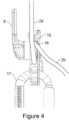
- the secondary rope-engaging means is positioned adjacent the load-bearing outgoing rope so that as the rope leaves the camlock under tension from the anchor point the incoming rope rubs against the outgoing rope from the camlock in this region to provide additional frictional resistance to the secondary rope engaging means.
- the incoming rope presses against the tensioned outgoing rope from the camlock, forcing the tensioned part of the rope to move sideways in the horizontal direction, effectively providing a friction-inducing kink in the rope as it leaves the descender without any further rope-guiding interaction from the climber, thereby allowing the climber a free hand for other use, such as carrying a weapon.
- the contoured flange of the secondary rope-engaging means is in the form of an outwardly extending wing having a trailing end relative to the direction of rope travel through the camlock during descent shaped to be smoothly contiguous with the body of the descender in that region, and having a leading end in the form of an open hook of diameter generally corresponding to the diameter of a climbing rope for use therewith, thereby allowing the climber to guide the rope against the hook in order to increase frictional resistance during descent.
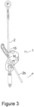
- a rope descender 1 is shown in its fully open condition for receiving a climbing rope 2 wound around a camlock 3, the camlock acting, in use, as the primary rope-engaging means for imparting friction to the rope 2 and including gripping teeth (not shown) for that purpose.
- the camlock 3 is constrained to rock about a flanged pivot pin 4 within the limits imposed by an inner cam 5 which also serves to provide a mechanical advantage to the camlock in the manner as described in D1.
- a rear plate 6 having a bore 7 for receiving a carabiner (not shown).
- a camshaft 8 Within the camlock 3 is a camshaft 8 to which is fixed at its front end the inner cam 5.
- the trailing end 2b of the rope 2 can be manipulated by the other hand of the climber (not shown) by moving the rope arcuately in the directions arrowed, the direction of movement corresponding to an increase in the angle by which the trailing end 2b of the rope 2 is forced to turn before reaching the rope entry guide/pivot post 10 of the descender 1.
- the climber can operate the camlock using one hand and can control the angular position of the trailing end 2b of the rope relative to the secondary rope-engaging means 14 using the other hand before the rope enters the descender 1.
- the free end 2b of the rope is left to dangle freely, leaving the climber with a free hand.
Landscapes
- Health & Medical Sciences (AREA)
- General Health & Medical Sciences (AREA)
- Business, Economics & Management (AREA)
- Emergency Management (AREA)
- Emergency Lowering Means (AREA)
Claims (4)
- Descendeur (1) pour contrôler la descente d'un grimpeur le long d'une corde (2) fixée à un point d'ancrage (P), le descendeur comprenant un moyen d'engagement de corde primaire sous la forme d'un verrou à came (3) et d'un guide d'entrée de corde (10) associé, le verrou à came ayant une surface de freinage de corde pouvant coopérer avec le guide d'entrée de corde pour verrouiller partiellement ou totalement la corde en réponse à un mouvement de la corde à travers le verrou à came, et un moyen de poignée (9) pour déverrouiller de manière ajustable le verrou à came pour libérer ainsi totalement ou partiellement la corde et permettre ensuite la poursuite de la descente depuis le point d'ancrage, et un moyen d'engagement de corde secondaire (15, 16) avant le moyen d'engagement de corde primaire (3, 10) par rapport à la direction de déplacement de la corde pendant une descente, CARACTÉRISÉ EN CE QUE le moyen d'engagement de corde secondaire (15, 16) est disposé avant et immédiatement adjacent au moyen d'engagement de corde primaire (3, 10) et ayant une surface de freinage d'engagement de corde (16) supplémentaire adaptée pour, lors de l'utilisation, conférer sélectivement un frottement supplémentaire ou alternatif à la corde avant qu'elle ne pénètre dans le moyen d'engagement de corde primaire et provoquer un engagement par frottement entre la corde lorsqu'elle pénètre dans le moyen d'engagement de corde primaire (3) et lorsqu'elle en sort.
- Descendeur (1) selon la revendication 1, CARACTÉRISÉ EN OUTRE EN CE QUE le moyen d'engagement de corde secondaire (15) inclut un crochet ouvert (16) fournissant une surface de freinage pour la corde lorsqu'elle est en engagement avec lui.
- Descendeur (1) selon la revendication 2, CARACTÉRISÉ EN OUTRE EN CE QUE le moyen d'engagement de corde secondaire (15) se présente sous la forme d'une bride profilée faisant saillie du corps du descendeur le long de la trajectoire de la corde avant qu'elle ne pénètre dans le guide d'entrée de corde (10), la bride (15) étant partiellement en forme de crochet (16) pour changer la direction de déplacement de la corde et augmenter ainsi le frottement sur la corde.
- Descendeur (1) selon la revendication 3, CARACTÉRISÉ EN OUTRE EN CE QUE la bride profilée du moyen d'engagement de corde secondaire (15, 16) se présente sous la forme d'une aile (15) s'étendant vers l'extérieur, ayant un bord de fuite (15a) par rapport à la direction de déplacement de corde à travers le verrou à came pendant la descente, formé pour être contigu sans-à-coups au corps du descendeur dans cette région, et ayant une extrémité avant sous la forme d'un crochet ouvert (16).
Applications Claiming Priority (2)
| Application Number | Priority Date | Filing Date | Title |
|---|---|---|---|
| GB1915078.8A GB2588225B (en) | 2019-10-18 | 2019-10-18 | Rope descenders |
| PCT/GB2020/000085 WO2021074557A1 (fr) | 2019-10-18 | 2020-10-16 | Descendeurs de câble |
Publications (3)
| Publication Number | Publication Date |
|---|---|
| EP4045153A1 EP4045153A1 (fr) | 2022-08-24 |
| EP4045153B1 true EP4045153B1 (fr) | 2025-04-16 |
| EP4045153C0 EP4045153C0 (fr) | 2025-04-16 |
Family
ID=68728123
Family Applications (1)
| Application Number | Title | Priority Date | Filing Date |
|---|---|---|---|
| EP20803230.0A Active EP4045153B1 (fr) | 2019-10-18 | 2020-10-16 | Descendeurs de câble |
Country Status (4)
| Country | Link |
|---|---|
| US (1) | US20240091568A1 (fr) |
| EP (1) | EP4045153B1 (fr) |
| GB (1) | GB2588225B (fr) |
| WO (1) | WO2021074557A1 (fr) |
Families Citing this family (2)
| Publication number | Priority date | Publication date | Assignee | Title |
|---|---|---|---|---|
| CN116495652A (zh) * | 2023-04-26 | 2023-07-28 | 福建省东山县辉永泰体育用品实业有限公司 | 一种高适用性的集成滑动器 |
| EP4643956A1 (fr) * | 2024-05-02 | 2025-11-05 | Grivel S.r.l. | Assurance d'escalade |
Family Cites Families (9)
| Publication number | Priority date | Publication date | Assignee | Title |
|---|---|---|---|---|
| FR2721522B1 (fr) * | 1994-06-23 | 1996-08-14 | Zedel | Descendeur débrayable à autoblocage de la corde. |
| DE19815194A1 (de) * | 1998-04-04 | 1999-10-07 | Brand & Schluttig Gmbh | Abseilgerät mit Paniksicherung |
| US7658264B2 (en) * | 2005-03-16 | 2010-02-09 | Kirk Martin Mauthner | Combination descender, pulley and force limiting rope brake |
| FR2904564B1 (fr) * | 2006-08-03 | 2008-11-07 | Zedel Soc Par Actions Simplifi | Appareil assureur et descendeur pour corde |
| NZ596748A (en) * | 2009-06-12 | 2013-04-26 | Capital Safety Group Australia Pty Ltd | Rope descender with self- acting brake |
| GB2522179B (en) * | 2013-11-14 | 2019-02-13 | Int Safety Components Ltd | Improvements in and relating to rope descenders |
| US11660475B2 (en) * | 2015-04-07 | 2023-05-30 | Harken, Incorporated | High load descender with adaptive release linkage |
| CN110072595B (zh) * | 2016-12-16 | 2020-06-12 | 3M创新有限公司 | 具有制动系统的坠落保护设备 |
| IT201700111007A1 (it) * | 2017-10-04 | 2019-04-04 | Camp Spa | Discensore |
-
2019
- 2019-10-18 GB GB1915078.8A patent/GB2588225B/en active Active
-
2020
- 2020-10-16 EP EP20803230.0A patent/EP4045153B1/fr active Active
- 2020-10-16 WO PCT/GB2020/000085 patent/WO2021074557A1/fr not_active Ceased
- 2020-10-16 US US17/766,753 patent/US20240091568A1/en not_active Abandoned
Also Published As
| Publication number | Publication date |
|---|---|
| GB201915078D0 (en) | 2019-12-04 |
| WO2021074557A1 (fr) | 2021-04-22 |
| EP4045153C0 (fr) | 2025-04-16 |
| US20240091568A1 (en) | 2024-03-21 |
| GB2588225A (en) | 2021-04-21 |
| GB2588225B (en) | 2024-01-03 |
| EP4045153A1 (fr) | 2022-08-24 |
Similar Documents
| Publication | Publication Date | Title |
|---|---|---|
| EP1259300B1 (fr) | Descendeur a manette de blocage bidirectionnelle | |
| AU2010258092B2 (en) | Descender with self- acting brake | |
| US11097136B2 (en) | High load descender with adaptive release linkage | |
| US8209823B2 (en) | Belay and/or rappelling accessory | |
| US6029777A (en) | Descender | |
| AU2016222270B2 (en) | Improved descender | |
| US10583315B2 (en) | High load descender with adaptive release linkage | |
| US20030051944A1 (en) | Descent control device | |
| WO2003015598A2 (fr) | Dispositif d'assurage ou de rappel pour sports de grimpe ou analogues | |
| EP4045153B1 (fr) | Descendeurs de câble | |
| EP0694317A2 (fr) | Dispositif de freinage de voie à commande manuelle | |
| US12343570B2 (en) | Descent control device | |
| AU757395B2 (en) | Descender with two-way locking lever | |
| WO2020136548A1 (fr) | Dispositif de freinage et/ou de blocage d'une corde |
Legal Events
| Date | Code | Title | Description |
|---|---|---|---|
| STAA | Information on the status of an ep patent application or granted ep patent |
Free format text: STATUS: UNKNOWN |
|
| STAA | Information on the status of an ep patent application or granted ep patent |
Free format text: STATUS: THE INTERNATIONAL PUBLICATION HAS BEEN MADE |
|
| PUAI | Public reference made under article 153(3) epc to a published international application that has entered the european phase |
Free format text: ORIGINAL CODE: 0009012 |
|
| STAA | Information on the status of an ep patent application or granted ep patent |
Free format text: STATUS: REQUEST FOR EXAMINATION WAS MADE |
|
| 17P | Request for examination filed |
Effective date: 20220317 |
|
| AK | Designated contracting states |
Kind code of ref document: A1 Designated state(s): AL AT BE BG CH CY CZ DE DK EE ES FI FR GB GR HR HU IE IS IT LI LT LU LV MC MK MT NL NO PL PT RO RS SE SI SK SM TR |
|
| DAV | Request for validation of the european patent (deleted) | ||
| DAX | Request for extension of the european patent (deleted) | ||
| GRAP | Despatch of communication of intention to grant a patent |
Free format text: ORIGINAL CODE: EPIDOSNIGR1 |
|
| STAA | Information on the status of an ep patent application or granted ep patent |
Free format text: STATUS: GRANT OF PATENT IS INTENDED |
|
| INTG | Intention to grant announced |
Effective date: 20240820 |
|
| GRAS | Grant fee paid |
Free format text: ORIGINAL CODE: EPIDOSNIGR3 |
|
| RBV | Designated contracting states (corrected) |
Designated state(s): AL AT BE BG CH CY CZ DE DK EE ES FI FR GR HR HU IE IS IT LI LT LU LV MC MK MT NL NO PL PT RO RS SE SI SK SM TR |
|
| GRAA | (expected) grant |
Free format text: ORIGINAL CODE: 0009210 |
|
| STAA | Information on the status of an ep patent application or granted ep patent |
Free format text: STATUS: THE PATENT HAS BEEN GRANTED |
|
| AK | Designated contracting states |
Kind code of ref document: B1 Designated state(s): AL AT BE BG CH CY CZ DE DK EE ES FI FR GR HR HU IE IS IT LI LT LU LV MC MK MT NL NO PL PT RO RS SE SI SK SM TR |
|
| REG | Reference to a national code |
Ref country code: CH Ref legal event code: EP Ref country code: DE Ref legal event code: R096 Ref document number: 602020049620 Country of ref document: DE |
|
| REG | Reference to a national code |
Ref country code: IE Ref legal event code: FG4D |
|
| U01 | Request for unitary effect filed |
Effective date: 20250508 |
|
| U07 | Unitary effect registered |
Designated state(s): AT BE BG DE DK EE FI FR IT LT LU LV MT NL PT RO SE SI Effective date: 20250515 |
|
| U20 | Renewal fee for the european patent with unitary effect paid |
Year of fee payment: 6 Effective date: 20250804 |
|
| PG25 | Lapsed in a contracting state [announced via postgrant information from national office to epo] |
Ref country code: ES Free format text: LAPSE BECAUSE OF FAILURE TO SUBMIT A TRANSLATION OF THE DESCRIPTION OR TO PAY THE FEE WITHIN THE PRESCRIBED TIME-LIMIT Effective date: 20250416 |
|
| PG25 | Lapsed in a contracting state [announced via postgrant information from national office to epo] |
Ref country code: NO Free format text: LAPSE BECAUSE OF FAILURE TO SUBMIT A TRANSLATION OF THE DESCRIPTION OR TO PAY THE FEE WITHIN THE PRESCRIBED TIME-LIMIT Effective date: 20250716 Ref country code: GR Free format text: LAPSE BECAUSE OF FAILURE TO SUBMIT A TRANSLATION OF THE DESCRIPTION OR TO PAY THE FEE WITHIN THE PRESCRIBED TIME-LIMIT Effective date: 20250717 |
|
| PG25 | Lapsed in a contracting state [announced via postgrant information from national office to epo] |
Ref country code: PL Free format text: LAPSE BECAUSE OF FAILURE TO SUBMIT A TRANSLATION OF THE DESCRIPTION OR TO PAY THE FEE WITHIN THE PRESCRIBED TIME-LIMIT Effective date: 20250416 |
|
| PG25 | Lapsed in a contracting state [announced via postgrant information from national office to epo] |
Ref country code: HR Free format text: LAPSE BECAUSE OF FAILURE TO SUBMIT A TRANSLATION OF THE DESCRIPTION OR TO PAY THE FEE WITHIN THE PRESCRIBED TIME-LIMIT Effective date: 20250416 |
|
| PG25 | Lapsed in a contracting state [announced via postgrant information from national office to epo] |
Ref country code: RS Free format text: LAPSE BECAUSE OF FAILURE TO SUBMIT A TRANSLATION OF THE DESCRIPTION OR TO PAY THE FEE WITHIN THE PRESCRIBED TIME-LIMIT Effective date: 20250716 |
|
| PG25 | Lapsed in a contracting state [announced via postgrant information from national office to epo] |
Ref country code: IS Free format text: LAPSE BECAUSE OF FAILURE TO SUBMIT A TRANSLATION OF THE DESCRIPTION OR TO PAY THE FEE WITHIN THE PRESCRIBED TIME-LIMIT Effective date: 20250816 |
|
| PG25 | Lapsed in a contracting state [announced via postgrant information from national office to epo] |
Ref country code: SM Free format text: LAPSE BECAUSE OF FAILURE TO SUBMIT A TRANSLATION OF THE DESCRIPTION OR TO PAY THE FEE WITHIN THE PRESCRIBED TIME-LIMIT Effective date: 20250416 |
|
| PG25 | Lapsed in a contracting state [announced via postgrant information from national office to epo] |
Ref country code: CZ Free format text: LAPSE BECAUSE OF FAILURE TO SUBMIT A TRANSLATION OF THE DESCRIPTION OR TO PAY THE FEE WITHIN THE PRESCRIBED TIME-LIMIT Effective date: 20250416 |
|
| PG25 | Lapsed in a contracting state [announced via postgrant information from national office to epo] |
Ref country code: SK Free format text: LAPSE BECAUSE OF FAILURE TO SUBMIT A TRANSLATION OF THE DESCRIPTION OR TO PAY THE FEE WITHIN THE PRESCRIBED TIME-LIMIT Effective date: 20250416 |
|
| PLBE | No opposition filed within time limit |
Free format text: ORIGINAL CODE: 0009261 |
|
| STAA | Information on the status of an ep patent application or granted ep patent |
Free format text: STATUS: NO OPPOSITION FILED WITHIN TIME LIMIT |
|
| REG | Reference to a national code |
Ref country code: CH Ref legal event code: L10 Free format text: ST27 STATUS EVENT CODE: U-0-0-L10-L00 (AS PROVIDED BY THE NATIONAL OFFICE) Effective date: 20260225 |
|
| 26N | No opposition filed |
Effective date: 20260119 |