EP4045406B1 - Siège passager d'aéronef avec connection enfichable - Google Patents
Siège passager d'aéronef avec connection enfichable Download PDFInfo
- Publication number
- EP4045406B1 EP4045406B1 EP21714096.1A EP21714096A EP4045406B1 EP 4045406 B1 EP4045406 B1 EP 4045406B1 EP 21714096 A EP21714096 A EP 21714096A EP 4045406 B1 EP4045406 B1 EP 4045406B1
- Authority
- EP
- European Patent Office
- Prior art keywords
- plug
- seat
- aircraft passenger
- passenger seat
- divider
- Prior art date
- Legal status (The legal status is an assumption and is not a legal conclusion. Google has not performed a legal analysis and makes no representation as to the accuracy of the status listed.)
- Active
Links
Images


Classifications
-
- B—PERFORMING OPERATIONS; TRANSPORTING
- B64—AIRCRAFT; AVIATION; COSMONAUTICS
- B64D—EQUIPMENT FOR FITTING IN OR TO AIRCRAFT; FLIGHT SUITS; PARACHUTES; ARRANGEMENT OR MOUNTING OF POWER PLANTS OR PROPULSION TRANSMISSIONS IN AIRCRAFT
- B64D11/00—Passenger or crew accommodation; Flight-deck installations not otherwise provided for
- B64D11/06—Arrangements of seats, or adaptations or details specially adapted for aircraft seats
- B64D11/0639—Arrangements of seats, or adaptations or details specially adapted for aircraft seats with features for adjustment or converting of seats
- B64D11/064—Adjustable inclination or position of seats
-
- B—PERFORMING OPERATIONS; TRANSPORTING
- B64—AIRCRAFT; AVIATION; COSMONAUTICS
- B64D—EQUIPMENT FOR FITTING IN OR TO AIRCRAFT; FLIGHT SUITS; PARACHUTES; ARRANGEMENT OR MOUNTING OF POWER PLANTS OR PROPULSION TRANSMISSIONS IN AIRCRAFT
- B64D11/00—Passenger or crew accommodation; Flight-deck installations not otherwise provided for
- B64D11/06—Arrangements of seats, or adaptations or details specially adapted for aircraft seats
- B64D11/0648—Lower frame constructions
-
- B—PERFORMING OPERATIONS; TRANSPORTING
- B64—AIRCRAFT; AVIATION; COSMONAUTICS
- B64D—EQUIPMENT FOR FITTING IN OR TO AIRCRAFT; FLIGHT SUITS; PARACHUTES; ARRANGEMENT OR MOUNTING OF POWER PLANTS OR PROPULSION TRANSMISSIONS IN AIRCRAFT
- B64D11/00—Passenger or crew accommodation; Flight-deck installations not otherwise provided for
- B64D11/06—Arrangements of seats, or adaptations or details specially adapted for aircraft seats
- B64D11/0627—Seats combined with storage means
- B64D11/0636—Personal storage means or waste disposal bags
-
- B—PERFORMING OPERATIONS; TRANSPORTING
- B60—VEHICLES IN GENERAL
- B60N—SEATS SPECIALLY ADAPTED FOR VEHICLES; VEHICLE PASSENGER ACCOMMODATION NOT OTHERWISE PROVIDED FOR
- B60N2/00—Seats specially adapted for vehicles; Arrangement or mounting of seats in vehicles
- B60N2/68—Seat frames
- B60N2/682—Joining means
- B60N2002/684—Joining means the back rest being mounted or joined with an easy attachment system to the seat
-
- Y—GENERAL TAGGING OF NEW TECHNOLOGICAL DEVELOPMENTS; GENERAL TAGGING OF CROSS-SECTIONAL TECHNOLOGIES SPANNING OVER SEVERAL SECTIONS OF THE IPC; TECHNICAL SUBJECTS COVERED BY FORMER USPC CROSS-REFERENCE ART COLLECTIONS [XRACs] AND DIGESTS
- Y02—TECHNOLOGIES OR APPLICATIONS FOR MITIGATION OR ADAPTATION AGAINST CLIMATE CHANGE
- Y02T—CLIMATE CHANGE MITIGATION TECHNOLOGIES RELATED TO TRANSPORTATION
- Y02T50/00—Aeronautics or air transport
- Y02T50/40—Weight reduction
Definitions
- the invention relates to a passenger seat with a connecting device and a row of seats formed from several such passenger seats.
- Passenger seats or rows of seats consisting of several passenger seats arranged next to one another are known for equipping passenger aircraft.
- the passenger seats can have a variety of embodiments.
- Passenger seats, for example, are from the EP 3 459 852 A1 or the US 2017/0297456 A1 known.
- the DE 10 2008 020 156 A1 shows a well-known vehicle seat.
- the passenger seat should be constructed in such a way that it passes the tests provided for in the safety guidelines, in particular crash tests. This requires stable connections between various components of the passenger seat.
- the seat belt is preferably designed as a lap belt and is connected, for example, to a frame and/or a seat divider of the passenger seat at, for example, two belt connection points.
- the object of the present invention is to provide an improved passenger seat with increased stability.
- the invention is based on a passenger seat with a frame which is provided for attachment to a floor of a passenger cabin, the frame comprising a seat divider and spars running transversely to the seat direction, the seat divider being held by the spars, an enclosure with a structural component is provided, wherein the housing at least partially surrounds a backrest.
- the passenger seat includes a headrest, a backrest, a seat bottom and a leg rest.
- these, for example, four essential parts of the passenger seat are preferably connected to one another via fittings and/or joints, advantageously adjustable, in particular adjustable relative to one another.
- Bottom refers to the floor of the passenger cabin, while top designates an opposite position, which is in particular vertically spaced from the bottom.
- the structural component, the seat divider and the bars are made of a metal material, advantageously Aluminum, another light and stable material, and/or, for example, made of a composite material, in particular made of a carbon fiber composite material.
- all components of the passenger seat are optimized with regard to their materials and the associated weight.
- the shape of the components is also optimized in terms of weight, so that the components have, for example, specifically selected material recesses, which contribute to saving the weight of the respective component.
- the passenger seat can be arranged with the frame on the floor of a passenger cabin.
- the frame includes the seat divider and bars running transversely to the direction of the seat, with a first front bar and a second bar arranged behind it, viewed in the direction of the seat. Both bars are preferably arranged on the seat divider.
- the two spars run at a distance, in particular mostly parallel to one another.
- the seat divider is designed as a mechanically stable component of the passenger seat.
- the seat divider is designed to absorb forces that act on the passenger seat in the event of a crash and/or to direct them towards the floor of the passenger cabin.
- the seat divider has a height, a width and a depth.
- the width of the seat divider is preferably smaller than the depth of the seat divider.
- the height of the seat divider results from a dimension in the vertical direction in relation to the passenger seat.
- the height of the seat divider is preferably a multiple of the width and/or the depth of the seat divider.
- the enclosure is firmly arranged on the seat divider.
- the enclosure includes the structural component.
- the enclosure at least partially surrounds the backrest of the passenger seat.
- the passenger seat includes the enclosure, which is arranged in the area of the backrest.
- the backrest is adjustable in the area of the housing, relative to the housing.
- the enclosure is stationary in the passenger cabin, e.g. fixed in position and in particular not movable when adjusting the backrest.
- the enclosure can be arranged on the seat divider.
- the enclosure preferably covers the structural component, which is arranged, for example, within the enclosure.
- the housing is shell-shaped and/or U-shaped.
- the two seat dividers are arranged at a distance from one another.
- the two seat dividers are preferably arranged parallel to one another.
- two levels, each spanned from the height and the depth of the seat divider are arranged at least approximately parallel to one another.
- the passenger seat is delimited on both sides, in particular on the outside, by the seat dividers, advantageously in the area of the seat bottom.
- the seat divider is designed to be mechanically resilient in such a way that, for example, the belt connection points for the passenger's seat belt can be arranged on the seat divider, e.g. can be screwed on.
- the structural component is arranged on the seat divider.
- the structural component is arranged above the seat divider.
- the structural component has a width, a height and a depth.
- the structural component is preferably designed in the form of a strip, for example the height is a multiple of the depth and/or the width of the structural component.
- the core of the invention is that the seat divider is connected to the structural component via a connecting device, wherein the connecting device is designed as a plug connection.
- the connecting device is preferably designed as the plug connection.
- the connecting device advantageously achieves a very stable connection between the seat divider and the structural component.
- the connecting device is intended to absorb forces that may arise in the event of a crash and/or to transmit them to the support leg and/or the cabin floor via the seat divider.
- the connecting device enables simple and/or quick assembly from several parts when assembling the passenger seat.
- the seat dividers and the structural components are components of the passenger seat that can be preassembled separately.
- the connecting device in particular the plug connection, is arranged on each seat divider of the passenger seat.
- the structural component is at least partially covered by the housing.
- the housing is made of plastic. This means that almost any form of enclosure can be created.
- the enclosure for example, makes it more comfortable to sit on a passenger seat arranged behind it. A passenger sitting there is advantageously not significantly affected or disturbed by an adjustment of the backrest of the front passenger seat viewed in the direction of the seat, since the housing is advantageously designed to be fixed in position.
- the connecting device comprises a first plug-in element and a second plug-in element, the first plug-in element being arranged on the seat divider and the second plug-in element being arranged on the structural component.
- the plug connection advantageously comprises the first and the second plug element.
- the first plug-in element is arranged, in particular formed, in one piece on and/or from the upper end of the seat divider.
- the first plug-in element is formed and/or shaped, for example milled out, from the material of the seat divider.
- the first plug-in element can be attached, in particular screwed, and/or riveted to the upper end of the seat divider.
- the second plug-in element is advantageously arranged on the structural component.
- the second plug-in element is fixed to the structural component, preferably in a non-detachable manner, for example by means of rivets.
- the second plug-in element is formed, for example, from the structural component and/or shaped and/or arranged in one piece on the structural component.
- the connecting device is preferably designed as a type of tongue-and-groove connection.
- the plug connection is designed as a type of tongue and groove connection.
- the first plug-in element is designed as a tongue of the tongue-and-groove connection.
- the first plug-in element, designed as the spring is a separating element which advantageously has a beveled slip-on surface, for example designed as a chamfer.
- the second plug-in element is advantageously designed as a type of groove in the tongue-and-groove connection.
- the second plug-in element comprises an opening, in particular a slot-like recess, advantageously a groove.
- the groove is preferably formed and/or delimited by opposing walls or cheeks.
- the first plug-in element can be arranged in the second plug-in element, particularly when it is a tongue-and-groove connection acts.
- the first plug-in element can be plugged into the second plug-in element, in particular completely pluggable, and/or retractable, in particular completely retractable.
- the first plug-in element is arranged on the seat divider, the first plug-in element comprising a recess, the recess having a depth of at least 50% of the depth of the seat divider when viewed in the seat direction.
- the first plug-in element includes the recess.
- the first plug-in element with the recess is preferably arranged in the upper region of the seat divider, in particular at the upper end.
- a recess is preferably arranged on both sides of the first plug-in element.
- the two recesses are arranged opposite each other.
- the separating element is advantageously arranged between the recesses, in particular the recesses adjoin the separating element on both sides.
- the recess is 50%, 60%, 70%, 80%, 85%, 90%, 95%, 99%, 100% of the depth of the seat divider, viewed in the direction of the seat. In particular, other arbitrary values between 50% and 100% are also possible.
- a height of the recess is approximately the same size as the depth of the recess.
- the recess has a width which corresponds in particular to 10% to 40%, preferably 25%, of the width of the seat divider.
- Two recesses together preferably result in a width between 20% and 80%, preferably 50%, of the width of the seat divider; in particular, other arbitrary values between 20% and 80% are also possible.
- the recesses on both sides of the seat divider are similar, in particular of the same design. Due to the advantageous design with opposite recesses, there is an area between the two recesses, the separating element, which also corresponds to approximately 50% of the width of the seat divider. For example, the width of the separating element is between 20% and 80% of the width seat divider.
- the width of two recesses and the width of the separating element corresponds to the width of the seat divider.
- the separating element advantageously comprises a passage, for example a hole.
- the feedthrough designed for example as a screw hole
- the plug connection can be fixed in the arranged state of the two plug elements.
- feedthroughs in the two plug-in elements for fixation.
- a further opening in particular as a larger hole, is arranged on the separating element.
- the larger hole is intended to save material and thus reduce the weight of the component.
- the second plug-in element comprises a tongue.
- the tongue is advantageously formed on the second plug-in element, in particular in one piece.
- the second plug-in element comprises several sections, in particular two sections. For example, there is an upper section and a lower section.
- the upper section is designed as a connection surface to the structural component.
- the lower section of the second plug-in element is designed as the tongue.
- the tongue can be arranged in the recess of the first plug-in element on the seat divider.
- the tongue is preferably designed as a counterpart to the first plug-in element.
- both plug-in elements are designed in such a way that they work together in a form-fitting manner.
- the two plug-in elements When arranged, the two plug-in elements preferably form a plug-in state.
- the tongue has a height which advantageously corresponds to the height of the recess in the first plug-in element on the seat divider.
- the surfaces of the two plug-in elements that touch each other in the plugged state, for example the recess of the first plug-in element and a side surface of the tongue, are contact surfaces of the first and/or second plug-in element.
- the first plug-in element comprises exactly one recess and the second plug-in element comprises exactly one tongue.
- exactly one recess and exactly one tongue form the connecting device, in particular the plug connection.
- the second plug-in element preferably comprises two tongues, the tongues being arranged at a distance from one another on the structural component.
- the distance between the two tongues is determined by the width of the structural component at a connection point.
- the type of groove of the tongue-and-groove connection is formed by the free space between two tongues.
- the tongue has a height which is 50% to 150% of the depth of the recess on the first plug-in element.
- the height of the tongue is 30% to 200% of the depth of the recess, preferably 75% to 125%, in particular 100% of the depth of the recess.
- each tongue advantageously have a width of approximately 50% of the width of the seat divider.
- each tongue has a width of between 10% and 40% of the width of the seat divider, in particular 25% of the width of the seat divider.
- the second plug-in element preferably has a height between 150% and 500% of the height of the tongue, for example 200% to 400%, preferably 300%.
- the first plug-in element advantageously comprises a guide surface.
- the guide surface is designed as an area that protrudes compared to the surface of the recess.
- the guide surface is a boundary of the area of the recess.
- the guide surface advantageously projects at an angle from the surface of the recess. When plugged in, the surface of the recess is the contact surface of the first plug-in element.
- the first plug-in element comprises a plurality of guide surfaces, in particular two, which are designed opposite one another.
- the two opposing guide surfaces are approximately vertical, based on the orientation of the passenger seat.
- the two guide surfaces are designed as a front guide surface and a rear guide surface, the direction being selected in relation to the seat direction.
- the rear guide surface viewed in the seat direction, is designed such that the rear guide surface extends from the lower end of the first plug-in element to the upper end of the first plug-in element.
- the second plug-in element advantageously slides along the rear guide surface when the connecting device is assembled.
- the front guide surface seen in the seat direction is designed obliquely, in particular at an angle to the connecting surface. This advantageously results in the second plug-in element being guided along, in particular sliding along, this guide surface when the plug-in connection is assembled.
- the front guide surface at the upper end of the front guide surface there is a starting slope in the form of a curvature with a radius, the starting slope making it easier to assemble the plug connection.
- the two plug-in elements when arranged, have approximately the same width as the seat divider.
- the two plug-in elements When assembled, the two plug-in elements preferably have a width which is approximately the same as the width of the seat divider.
- the two plug-in elements When plugged in, the two plug-in elements advantageously have a width equal to the width of the seat divider.
- the first plug-in element in the area of the recess has a width of 10% to 80%, in particular 50%, of the width of the seat divider.
- the first plug-in element has two opposite recesses.
- these two recesses together correspond to approximately half the width of the seat divider.
- each recess corresponds to between 10% and 40% of the width of the seat divider, preferably 25%.
- the width of the separating element preferably results from the width of the first plug-in element, in particular the width of the seat divider below the recess, minus the width of the two recesses.
- the first plug-in element comprises an upper and a lower end, the upper end comprising at least one beveled plug-on surface and the lower end being a surface projecting from the surface of the recess.
- the upper end is advantageously designed as a slip-on bevel.
- the upper end is preferably designed on both sides as a beveled slip-on surface, for example a chamfer.
- the two slip-on surfaces are arranged at an angle to one another, for example in the shape of a roof.
- the beveled plug-on surfaces are closer together at the top end of the first plug-in element than in the direction of the lower end of the recess.
- the first plug-in element comprises a connecting surface at its lower end of the recess.
- the connecting surface is designed as a surface projecting from the surface of the recess.
- the connecting surface is preferably aligned horizontally, in particular approximately parallel to the floor of the passenger cabin.
- the two opposing guide surfaces are connected to one another by the connecting surface.
- one of the guide surfaces and the adjacent connecting surface are connected by a curvature, advantageously designed as a circular section, in particular with a radius.
- the two guide surfaces are connected to one another with the connecting surface with two different radii. Two equal radii are also possible.
- a larger radius than the other is particularly preferred Radius in the front curvature and a correspondingly smaller radius in the rear curvature, viewed in the direction of the seat.
- the connecting device in particular a fail-safe design of the plug connection.
- fixing the plug connection is only possible when the plug elements are in the correct position in one another.
- the slip-on bevels at the upper end of the first plug-in element position the second plug-in element during assembly in the direction of the width of the plug-in connection or in the direction of the width of the seat divider.
- the two guide surfaces result in a further positioning of the second plug-in element relative to the first plug-in element when assembled in the direction of the depth of the plug-in elements or in the direction of the depth of the seat divider.
- the structural component preferably has a horizontal surface.
- the horizontal surface is a lower end of the structural component.
- the horizontal area results from the width and depth of the structural component.
- the horizontal surface of the structural component is designed approximately parallel to the upper end of the first plug-in element.
- the structural component has a protruding nose at the lower end, particularly in the area of the horizontal surface.
- the protruding nose is formed from the structural component and/or can be produced in one piece from the structural component. It is also possible to fix the nose to the structural component using, for example, screws and/or rivets.
- the protruding one is Nose arranged in the seating direction in front of the connecting device on the structural component.
- the second plug-in element has a connection surface with which the second plug-in element is arranged on the structural component.
- a connection surface with which the second plug-in element is arranged on the structural component.
- the connection surface is designed for fixation on the structural component.
- the connection surface is the upper section of the second plug-in element, preferably arranged at a distance from the tongue on the second plug-in element.
- the tongue borders the connection surface.
- the second plug-in element preferably has two parts, each of which is formed, for example, from a tongue and a connecting surface.
- a row of seats preferably comprises at least two passenger seats according to one of the preceding design options.
- two of the passenger seats described above are arranged in a row of seats, in particular as a pair of passenger seats.
- the pair of passenger seats is arranged such that two support legs, which can be connected to the cabin floor, in particular to holders in the cabin floor, are sufficient.
- the support legs are connected to one another with the spar; two spars are preferably present.
- the support legs are fixed to the spar using a disc hub connection.
- the seat dividers can be arranged on the bars just as advantageously, so that the row of seats can be formed.
- the pair of passenger seats preferably comprises four seat dividers with four connecting devices for connecting four structural components.
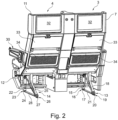
- Figure 1 shows a seat row 1 with a seating direction 2 with two passenger seats 3 and 4.
- position and direction information such as front, back, top and bottom refer to the seat direction 2 and the usable state of seat row 1.
- the passenger seat 3 has a seat base 5, a backrest 6 and an enclosure 7 on the back of the backrest 6. Following a front end region of the seat base 5, there is a preferably foldable leg rest 8, which can be folded about a horizontal axis.
- the passenger seat 4 includes a seat base 9, a backrest 10, an enclosure 11 and a leg rest 12.
- the seat bottom 5, 9, the backrests 6, 10 and the leg rests 8, 12 include preferably ergonomically shaped padding.
- the passenger seats 3 and 4 can be mounted on a cabin floor of a flight cabin of an associated aircraft via two support legs 13 and 14.
- the support leg 13 has a mounting point 17 on a lower end region 16 of a front strut 15 and a further mounting point 20 on a lower end region 19 of a rear strut 18.
- a strut element 21 is provided between the end regions 16 and 19.
- the support leg 14 has a mounting point 24 on a lower end region 23 of a front strut 22 and a further mounting point 27 on a lower end region 26 of a rear strut 25.
- a strut element 28 is provided between the end regions 23 and 26.
- the row of seats 1 also has an outer armrest 29 on the side of the passenger seat 3 and an outer armrest 30 on the side of the passenger seat 4. Between the two passenger seats 3 and 4 there is preferably a console 31 at the level of the two outer armrests 29 and 30, which can also be used by a passenger as an armrest.
- the associated backrest 6 or 10 is arranged in a shell shape of the respective housing 7 or 11.
- the backrest 6 or 10 is preferably movably guided in the housing 7 or 11 for setting different tilting positions, for example together with the associated slidably mounted seat bottom 5 or 9.
- the enclosures 7 and 11 are provided with further elements, e.g. B. each with additional functions on the back.
- a multimedia unit 32 for digital media is provided, for example with an electronic input and output device or with a touchscreen.
- a foldable storage element 33 is designed like a tray table with a table top.
- the storage elements 33 are shown in a folded-up, vertical and secured non-use position.
- a storage compartment 34 for example for storing magazines or brochures or other objects.
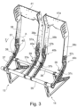
- Figure 3 shows a perspective view of a basic construction of the seat row 1 of the passenger seats 3, 4.
- the basic construction includes in particular a frame and several structural components 38, 38a, 38b, 38c, 41 and 41a.
- a seat divider 37 is preferably arranged on the bars 35 and 36.
- Seat dividers 37b, 37c for the passenger seat 4 are available.
- the seat dividers 37 to 37c have different material recesses.
- the seat dividers 37, 37a, 37b, 37c are preferably constructed the same, in particular identically.
- the seat divider 37 is designed in particular as a flat, angled, for example arcuate component.
- a connecting device 40 according to the invention is arranged at the upper end of the seat divider 37.
- a structural component 38 is advantageously connected to the seat divider 37 via the connecting device 40.
- the structural component 38a is connected to the seat divider 37a via the connecting device 40a.
- the structural component 38b is attached to the seat divider 37b by means of the connecting device 40b and also the structural component 38c is attached to the seat divider 37c by means of the connecting device 40c.
- a connecting structural component 41 is arranged on two structural components 38, 38a.
- the connecting structural component 41 is preferably attached to an upper end of the vertically aligned structural components 38, 38a.
- a connecting structural component 41a is arranged between the vertically aligned structural components 38b and 38c.
- the connecting structural component 41 or 41a preferably acts in a stiffening and/or mechanically stabilizing manner with the two vertical structural components 38 and 38a, or 38b and 38c.
- the connecting structural component 41 and the structural components 38, 38a are connected to one another by means of connecting means (not shown), for example angles and/or screws and/or rivets.
- connecting means not shown
- a one-piece design of the structural components with the connecting structural component is possible. The same applies to the connecting structure component 41a.
- the connecting structural component 41 or 41a is a plate-shaped element with a long and a short Side and a thickness formed.
- the connecting structural component is aligned such that the long side of the connecting structural component 41 or 41a is arranged in the horizontal direction with respect to the passenger seat.
- the three spatial directions width 61, depth 62, height 63 are in Figure 4 shown and relate to the orientation of the seat divider 37 or 37a, or 37b, or 37c.
- the connecting device 40 or 40c is arranged on the right and left on the outside of the seat divider 37 or 37c and on the structural component 38 or 38c.
- the connecting device 40a and 40b is preferably arranged on the centrally arranged seat dividers 37a and 37b.
- the connecting devices 40 and 40c differ from the connecting devices 40a and 40b in the shape of the connecting surfaces 57 and 57c to 57a and 57b.
- the respective outer structural components 38 and 38c also differ in their shape from the respective inner structural components 38a and 38b.
- there is a widening at the upper end of the structural component 38 while the structural component 38a has a widening at the lower end, in the area of the connecting surface 57a.
- a belt connection 39 is arranged on each seat divider 37, 37a, 37b, 37c, in particular all four arranged belt connections 39 are designed in the same way.
- the belt connection 39 is screwed to the seat dividers 37 to 37c; a seat belt with in particular a belt buckle and/or a hook and/or eyelet matched to the belt buckle can advantageously be attached to the belt connection 39.
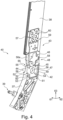
- FIG 4 is section A Figure 3 shown enlarged.
- the following statements apply to the connecting device 40, but also to the connecting devices 40a to 40c.
- connection device 40 is in Figure 4 shown in an unassembled state of seat divider 37 and structural component 38.
- the connecting device 40 preferably comprises a first plug-in element 42 and a second plug-in element 43.
- the first plug-in element 42 is preferably arranged at the upper end of the seat divider 37, which is aligned towards the structural component 38.
- the first plug-in element 42 is formed in one piece on the seat divider 37, in particular milled out of the material of the seat divider, for example, or produced by milling.
- the first plug-in element 42 has two opposite recesses, which are located on both sides of the separating element 44.
- the recesses are a flat material removal up to a depth T1, in particular both recesses are the same, so that the separating element 44 remains between the recesses.
- the recesses each have a vertically oriented contact surface 56.
- the contact surface 56 is also a boundary surface of the separating element 44; the contact surfaces 56 are preferably designed the same on both sides of the separating element 44.
- the contact surface 56 advantageously has a depth and a height. Both directions are indicated in relation to the orientation of the seat divider or passenger seat.
- the separating element 44 has, for example, an attachment bevel 55 at the upper end.
- the slip-on bevel 55 is preferably formed on an upper end region of the contact surface 56.
- the slip-on bevel 55 is designed in the same way on both sides of the separating element 44, so that the slip-on slopes 55 are aligned roof-shaped on the separating element 44.
- bushings 45 for example designed as screw holes, on the separating element 44.
- bushings 45 are preferably arranged on the contact surface 56, in particular symmetrically, for example according to the corners of a rectangle and/or square.
- a hole 47 which is larger than the bushings 45, is preferably arranged in the middle of the contact surface 56 and is provided, for example, to save weight.
- Each of the contact surfaces 56 is delimited on, for example three sides, surfaces projecting at an angle to the plane of the contact surface 56, for example by two vertically aligned guide surfaces 49 and 50 and a horizontally aligned connecting surface 51.
- the guide surfaces 49 and 50 are elongated and/or strip-shaped, in particular they are aligned vertically in the longitudinal direction.
- the connecting surface 51 is elongated and/or strip-shaped, in particular the connecting surface 51 is aligned horizontally in the longitudinal direction in relation to the passenger seat 3, 4.
- the guide surfaces 49 and 50 and the connecting surface 51 preferably protrude approximately at right angles from the contact surface 56.
- the guide surface 49 is connected to the connecting surface 51 via a concave curvature 54 with z. B. connected to a radius.
- the connecting surface 51 is preferably also connected to the guide surface 50 with a further concave curvature 53 with a, in particular a wider, radius.
- the guide surface 50 is formed at the front of the contact surface 56 when viewed in the seat direction.
- the guide surface 50 is preferably designed approximately vertically or with only a slight deviation from the vertical direction of the passenger seat.
- they are Guide surfaces 49 and 50 are designed differently in their deviation from the vertical direction.
- the rear guide surface 49 is higher than the front guide surface 50.
- the rear guide surface 49 extends over almost the entire height of the contact surface 56, while the front guide surface 50 only extends over a part, in particular approximately half, of the height of the contact surface 56.
- a starting slope 52 is arranged at the upper end of the guide surface 50.
- the approach bevel 52 is preferably designed as a convex curvature, in particular with a radius.
- placing the structural component 38 on the seat divider 37 is simplified by the starting bevel 52 and the slip-on bevels 55 in conjunction with the rear guide edge 51.
- the radius between the front guide surface 50 and the connecting surface 51 is larger than the radius between the rear guide surface 49 and the connecting surface 51. It is also possible the other way around, or for both radii to be the same.
- At least one tongue 48 is arranged on the second plug-in element 43 at the lower end, on the outside of the structural component 38.
- the second plug-in element 43 is constructed from two identical parts, each of which has the tongue 48 and a connecting surface 57.
- the tongues 48 are preferably attached to the structural component 38 at a distance. More preferably, the tongues 48 are designed the same way.
- the outer shape of the tongue 48 is matched to the guide surfaces 49, 50 and the connecting surface 51 in such a way that the border surfaces of the tongue 48 lie on these surfaces 49, 50, 51, and/or the surfaces 49, 50, 51 and the surrounding surfaces of the tongue 48 interact in a form-fitting manner.
- a material recess 58 that is open to the outside on one side is arranged on the tongue 48.
- the material recess 58 advantageously serves to reduce weight.
- a contact surface 56a is arranged on the tongue 48 opposite the material recess; in particular, the side of the tongue is designed as the contact surface 56a, which comes into contact with the contact surface 56 on the first plug-in element 42.
- the contact surface 56 is in flat contact with the contact surface 56a, or the two contact surfaces 56 and 56a are in mutual contact, at least partially.
- a feedthrough 46 preferably several feedthroughs 46 are present.
- the second plug-in element 43 is connected to the structural component 38 at the connection surface 57.
- An upper region 59 which adjoins the tongue 48, for example, preferably has a feedthrough 60.
- several bushings 60 are provided for rivets and/or screws. In Figure 4 No rivets and/or screws and/or other fasteners are shown.
- An advantageous process when joining the two plug-in elements 42 and 43 is as follows:
- the narrow or frontal edge surface of the tongue 48 corresponding to the rear guide surface 49 is guided through the guide surface 49 by a contact when placed.
- the two slip-on bevels 55 allow the position, in particular centering, of the second plug-in element 43 to the first plug-in element 42 to be adjusted in the width direction in relation to the seat divider.
- the starting bevel 52 enables the tongue 48 with the contact surface 56a to be easily fitted onto the contact surface 56.
- the connecting device 40 is shown in the assembled state.
- the second plug-in element 43 is placed on the first plug-in element 42 with the contact surfaces 56 in the area of the contact surface 56a.
- the separating element 44 is arranged, preferably completely, immersed and/or recessed between the two tongues 48.
- the dimensions of the two tongues 48 are selected such that the two tongues 48 can be fitted into the recesses on the first plug-in element 42.
- the tongues 48 fill the recesses on the seat divider 37 exactly or approximately exactly; in particular, tongues 48 are fitted into the recesses in such a way that, from the front in relation to the seat direction, an outer surface of the tongue 48 is flush with an outer surface of the seat divider 37.
- the separating element 44 is designed such that its width is approximately 50% of the width of the seat divider.
- the guide surfaces 49 and 50 and the connecting surface 51 each have a width of approximately 25% of the width of the seat divider 37.
- the width of the tongue 48 is matched to the width of the guide surfaces or the width of the recess on the seat divider 37. In particular, the width of the tongue 48 is approximately 25% of the width of the seat divider 37.
- the connecting device 40a differs from the connecting device 40a only in the connection surface 57 or 57a.
- the remaining features are corresponding. ⁇ u>Reference symbol list ⁇ /u> 1 row of seats 36 rear spar 2 Seating direction 37 Seat divider 3 Passenger seat 37a Seat divider 4 Passenger seat 37b Seat divider 5 Seat bottom 37c Seat divider 6 backrest 38 Structural component 7 Enclosure 38a Structural component 8th Leg rest 38b Structural component 9 Seat bottom 38c Structural component 10 backrest 39 Belt connection 11 Enclosure 40 Connection device 12 Leg rest 40a Connection device 13 Support leg 40b Connection device 14 Support leg 40c Connection device 15 strut 41 Connecting structure component 16 End area 17 Assembly site 41a Connecting structure component 18 strut 19 End area 42 first plug-in element 20 Assembly site 43 second plug-in element 21 Bracing element 44 Separator 22 strut 45 execution 23 End area 46 execution 24 Assembly site 47 Hole 25 strut 48 Tongue 26 End area 49 Guide surface 27 Assembly site
Landscapes
- Engineering & Computer Science (AREA)
- Aviation & Aerospace Engineering (AREA)
- Seats For Vehicles (AREA)
- Body Structure For Vehicles (AREA)
Claims (14)
- Siège passager d'aéronef (3, 4) comportant un cadre qui est destiné à être fixé à un plancher d'une cabine de passagers d'aéronef, le cadre comprenant un séparateur de sièges (37, 37a, 37b, 37c) et des barres (35, 36) s'étendant transversalement à la direction de siège, le séparateur de sièges (37, 37a, 37b, 37c) étant maintenu par les barres (35, 36), un logement (7, 11) comportant un composant structural (38, 38a, 38b, 38c, 41, 41a, 42, 42a) étant prévu, le logement (7, 11) du siège passager d'aéronef (3, 4) entourant au moins partiellement un dossier (6, 10) du siège passager d'aéronef (3, 4), le logement (7, 11) étant disposé fixement sur le séparateur de sièges (37, 37a, 37b, 37c), le dossier (6, 10) étant déplaçable par rapport au logement (7, 11) dans la région du logement (7, 11), le séparateur de sièges (37, 37a, 37b, 37c) étant relié au composant structural (38, 38a, 38b, 38c) par le biais d'un dispositif de liaison (40, 40a, 40b, 40c), le dispositif de liaison (40, 40a, 40b, 40c) étant réalisé sous la forme d'une liaison enfichable.
- Siège passager d'aéronef (3, 4) selon la revendication 1, caractérisé en ce que le dispositif de liaison (40, 40a, 40b, 40c) comprend un premier élément enfichable (42) et comprend un deuxième élément enfichable (43), le premier élément enfichable (42) étant disposé sur le séparateur de sièges (38, 38a, 38b, 38c) et le deuxième élément enfichable (43) étant disposé sur le composant structural (38, 38a, 38b, 38c).
- Siège passager d'aéronef (3, 4) selon l'une des revendications précédentes, caractérisé en ce que le dispositif de liaison (40, 40a, 40b, 40c) est réalisé sous la forme d'une liaison à rainure et languette.
- Siège passager d'aéronef (3, 4) selon la revendication 2 ou la revendication 3 dépendant de la revendication 2, caractérisé en ce que le premier élément enfichable (42) est disposé sur le séparateur de sièges (37, 37a, 37b, 37c), le premier élément enfichable (42) comprenant un évidement, l'évidement présentant, vu dans la direction de siège, une profondeur d'au moins 50% de la profondeur du séparateur de sièges (37, 37a, 37b, 37c) .
- Siège passager d'aéronef (3, 4) selon la revendication 2 ou l'une des revendications précédentes 3 et 4 dépendant de la revendication 2, caractérisé en ce que le deuxième élément enfichable (43) comprend une languette (48).
- Siège passager d'aéronef (3, 4) selon la revendication 2 ou l'une des revendications précédentes 3 à 5 dépendant de la revendication 2, caractérisé en ce que le deuxième élément enfichable (43) comprend deux languettes (48), les languettes (48) étant disposées de manière espacée l'une de l'autre sur le composant structural (38, 38a, 38b, 38c).
- Siège passager d'aéronef (3, 4) selon la revendication 5 dépendant de la revendication 4 ou selon la revendication 6 dépendant de la revendication 4, caractérisé en ce que la languette (48) présente une longueur, laquelle vaut de 50% à 150% de la profondeur de l'évidement sur le premier élément enfichable (42).
- Siège passager d'aéronef (3, 4) selon la revendication 2 ou l'une des revendications précédentes 3 à 7 dépendant de la revendication 2, caractérisé en ce que le premier élément enfichable (42) comprend une surface de guidage (49, 50, 51).
- Siège passager d'aéronef (3, 4) selon la revendication 2 ou l'une des revendications précédentes 3 à 8 dépendant de la revendication 2, caractérisé en ce que le premier élément enfichable (42) comprend plusieurs surfaces de guidage (49, 50, 51), en particulier deux, lesquelles sont réalisées en regard l'une de l'autre.
- Siège passager d'aéronef (3, 4) selon la revendication 2 ou l'une des revendications précédentes 3 à 9 dépendant de la revendication 2, caractérisé en ce que les deux éléments enfichables (42, 43) présentent, dans l'état agencé, approximativement la même largeur que le séparateur de sièges (37, 37a, 37b, 37c).
- Siège passager d'aéronef (3, 4) selon la revendication 4 ou l'une des revendications précédentes 5 à 10 dépendant de la revendication 4, caractérisé en ce que le premier élément enfichable (42) présente, dans la région de l'évidement, une largeur de 50% de la largeur du séparateur de sièges (37, 37a, 37b, 37c).
- Siège passager d'aéronef (3, 4) selon la revendication 4 ou l'une des revendications précédentes 5 à 11 dépendant de la revendication 4, caractérisé en ce que le premier élément enfichable (42) comprend une extrémité supérieure et une extrémité inférieure, l'extrémité supérieure comprenant au moins une surface biseautée (55) et l'extrémité inférieure étant une surface (51) faisant saillie par rapport à la surface de l'évidement.
- Siège passager d'aéronef (3, 4) selon la revendication 2 ou l'une des revendications précédentes 3 à 12 dépendant de la revendication 2, caractérisé en ce que le deuxième élément enfichable (43) présente une surface de connexion (57, 57a, 57b, 57c) par laquelle le deuxième élément enfichable (43) est disposé sur le composant structural (38, 38a, 38b, 38c).
- Rangée de sièges (1) comportant au moins deux sièges passagers d'aéronef (3, 4) selon l'une des revendications précédentes.
Applications Claiming Priority (2)
| Application Number | Priority Date | Filing Date | Title |
|---|---|---|---|
| DE102020106035.1A DE102020106035A1 (de) | 2020-03-05 | 2020-03-05 | Fluggastsitz mit einer Verbindungsvorrichtung sowie Sitzreihe |
| PCT/EP2021/055370 WO2021175939A1 (fr) | 2020-03-05 | 2021-03-03 | Siège de passager d'aéronef comportant une liaison par fiches |
Publications (2)
| Publication Number | Publication Date |
|---|---|
| EP4045406A1 EP4045406A1 (fr) | 2022-08-24 |
| EP4045406B1 true EP4045406B1 (fr) | 2023-09-13 |
Family
ID=75203251
Family Applications (1)
| Application Number | Title | Priority Date | Filing Date |
|---|---|---|---|
| EP21714096.1A Active EP4045406B1 (fr) | 2020-03-05 | 2021-03-03 | Siège passager d'aéronef avec connection enfichable |
Country Status (4)
| Country | Link |
|---|---|
| US (1) | US11724809B2 (fr) |
| EP (1) | EP4045406B1 (fr) |
| DE (1) | DE102020106035A1 (fr) |
| WO (1) | WO2021175939A1 (fr) |
Families Citing this family (3)
| Publication number | Priority date | Publication date | Assignee | Title |
|---|---|---|---|---|
| DE102020106037A1 (de) * | 2020-03-05 | 2021-09-09 | Zim Flugsitz Gmbh | Fluggastsitz und Sitzreihe |
| US12145731B2 (en) * | 2021-12-07 | 2024-11-19 | B/E Aerospace, Inc. | Aircraft seat base assembly |
| US11760491B1 (en) * | 2022-03-04 | 2023-09-19 | Safran Seats Usa Llc | Two-piece machine leg assembly for passenger seats |
Citations (1)
| Publication number | Priority date | Publication date | Assignee | Title |
|---|---|---|---|---|
| EP3459852B1 (fr) * | 2017-09-26 | 2020-08-12 | Airbus Operations GmbH | Dispositif de siège de passager, système de siège de passager et procédé d'installation d'un système de siège de passager |
Family Cites Families (28)
| Publication number | Priority date | Publication date | Assignee | Title |
|---|---|---|---|---|
| US3037812A (en) * | 1958-07-30 | 1962-06-05 | Benjamin F Monroe | Aircraft seat structure |
| US5253923A (en) * | 1991-08-21 | 1993-10-19 | Leroy Gootee | Seat assembly having wedged locking mechanism |
| FR2735730B1 (fr) * | 1995-06-21 | 1997-08-29 | Irausa Ing Sa | Dispositif de liaison articulee entre le dossier et l'assise d'un siege de vehicule |
| US5690386A (en) | 1995-06-21 | 1997-11-25 | Irausa Ingeniera S.A. | Device for articulated connection between the backrest and the seat part of a vehicle seat |
| US6352309B1 (en) | 2000-01-13 | 2002-03-05 | Be Aerospace, Inc. | Passenger sleeper seat |
| US6742842B2 (en) | 2002-07-03 | 2004-06-01 | B E Aerospace, Inc. | Passenger seat with privacy shell |
| GB0407126D0 (en) | 2004-03-30 | 2004-05-05 | Thompson James | Reclining seat |
| GB0426527D0 (en) | 2004-12-02 | 2005-01-05 | James Park Associates Ltd | Aircraft seat supporting structure |
| US7909407B2 (en) * | 2007-06-07 | 2011-03-22 | Lear Corporation | Vehicle seat connection |
| US8366044B2 (en) * | 2009-10-09 | 2013-02-05 | PAC Seating Systems, Inc. | Removable back shell for an aircraft seat |
| EP2785589B1 (fr) | 2011-09-02 | 2017-11-15 | Zodiac Seats France | Siège de luxe comportant une tablette repas escamotable et un accoudoir coulissant |
| CA2902891C (fr) * | 2013-04-08 | 2017-08-22 | B/E Aerospace, Inc. | Siege d'aeronef employant deux actionneurs de translation de siege et d'inclinaison de siege |
| US9834308B2 (en) | 2014-03-26 | 2017-12-05 | B/E Aerospace, Inc. | Aircraft passenger seat center console unit |
| US20170021930A1 (en) * | 2014-04-02 | 2017-01-26 | B/E Aerospace, Inc. | Cradle recline mechanism for aircraft passenger seat |
| WO2015153734A1 (fr) * | 2014-04-02 | 2015-10-08 | B/E Aerospace, Inc. | Mécanisme d'inclinaison de berceau pour siège d'aéronef à coque fixe |
| US9919803B2 (en) * | 2014-04-04 | 2018-03-20 | B/E Aerospace, Inc. | Aircraft seat base frame |
| US10124899B2 (en) * | 2014-06-03 | 2018-11-13 | Zodiac Seats Us Llc | Hybrid composite structural member |
| JP6339296B2 (ja) * | 2014-12-31 | 2018-06-06 | シンガポール・テクノロジーズ・エアロスペース・リミテッドSingapore Technologies Aerospace Ltd | シートサスペンションの設置方法及び乗客用シート |
| EP3620377B1 (fr) | 2015-04-08 | 2022-11-09 | Safran Seats USA LLC | Couverture de confidentialité |
| DE102015122816A1 (de) * | 2015-12-23 | 2017-06-29 | Recaro Aircraft Seating Gmbh & Co. Kg | Transportsitzsystem |
| US10232744B2 (en) * | 2016-01-12 | 2019-03-19 | Rockwell Collins, Inc. | Independent translating roller seat |
| US10676194B2 (en) | 2016-04-04 | 2020-06-09 | B/E Aerospace, Inc. | Contoured class divider |
| US10035433B2 (en) * | 2016-04-15 | 2018-07-31 | Freedman Seating Company | Frameless transit seat |
| EP3481721B1 (fr) * | 2016-07-07 | 2024-04-10 | Safran Seats USA LLC | Composants de siège composites |
| DE102018108351A1 (de) * | 2018-04-09 | 2019-10-10 | Zim Flugsitz Gmbh | Fluggastsitz mit einem bewegbar gelagerten Sitzboden |
| US11040775B2 (en) * | 2019-02-04 | 2021-06-22 | Dynamic Safety LLC | Seat assemblies, such as for use in aircraft, and associated systems and methods |
| DE102020106037A1 (de) * | 2020-03-05 | 2021-09-09 | Zim Flugsitz Gmbh | Fluggastsitz und Sitzreihe |
| US12054262B2 (en) * | 2020-05-27 | 2024-08-06 | Adient Aerospace, Llc | Seat assembly and passenger seat arrangement |
-
2020
- 2020-03-05 DE DE102020106035.1A patent/DE102020106035A1/de not_active Withdrawn
-
2021
- 2021-03-03 WO PCT/EP2021/055370 patent/WO2021175939A1/fr not_active Ceased
- 2021-03-03 EP EP21714096.1A patent/EP4045406B1/fr active Active
-
2022
- 2022-07-20 US US17/813,710 patent/US11724809B2/en active Active
Patent Citations (1)
| Publication number | Priority date | Publication date | Assignee | Title |
|---|---|---|---|---|
| EP3459852B1 (fr) * | 2017-09-26 | 2020-08-12 | Airbus Operations GmbH | Dispositif de siège de passager, système de siège de passager et procédé d'installation d'un système de siège de passager |
Also Published As
| Publication number | Publication date |
|---|---|
| WO2021175939A1 (fr) | 2021-09-10 |
| EP4045406A1 (fr) | 2022-08-24 |
| DE102020106035A1 (de) | 2021-09-09 |
| CN115315391A (zh) | 2022-11-08 |
| US20220348331A1 (en) | 2022-11-03 |
| US11724809B2 (en) | 2023-08-15 |
Similar Documents
| Publication | Publication Date | Title |
|---|---|---|
| EP4045406B1 (fr) | Siège passager d'aéronef avec connection enfichable | |
| DE102005042403B3 (de) | Modulares Sitzsystem für ein Fahrzeug | |
| DE3039934C2 (de) | Kopfstütze für Kraftfahrzeugsitze | |
| DE4437133C2 (de) | Trennwand für die Kabine eines Passagierflugzeuges | |
| EP1152917A1 (fr) | Siege-enfant, notamment pour utilisation mobile dans un avion | |
| DE4402864C2 (de) | Rückenlehnenpolster für Rücksitze von Kraftfahrzeugen | |
| EP3243694B1 (fr) | Procédé destiné au montage d'un système de sièges dans un véhicule et véhicule | |
| DE102016208533B4 (de) | Einstellbare Kopfstützenanordnung für Fahrzeugsitze | |
| DE10151741B4 (de) | Gleitschiene für einen Fahrzeugsitz | |
| EP4114732B1 (fr) | Siège de passager d'aéronef et rangée de sièges | |
| EP4045356B1 (fr) | Siège passager et rangée de sièges | |
| EP0830972A2 (fr) | Siège d'enfant avec une assise en forme de coquille | |
| EP3426527B1 (fr) | Véhicule pour le transport public de personnes | |
| EP4114733B1 (fr) | Siège de passager d'aéronef et rangée de sièges | |
| DE4140638A1 (de) | Kindersicherheitssitz | |
| EP3733516B1 (fr) | Dispositif siège pour une cabine d'avion, cabine d'avion et avion | |
| EP4114731A1 (fr) | Siège de passager d'aéronef comportant une enceinte | |
| DE102013213822B4 (de) | Bauteilanordnung für ein Lenkrad | |
| DE102022103946B4 (de) | Befestigungsvorrichtung für eine armlehne eines autositzes und autositze | |
| DE102007050091A1 (de) | Fahrzeugsitz mit einem drehbaren Rückenteil | |
| WO2024037842A1 (fr) | Agencement d'un système de siège arrière sur une structure de plancher d'une voiture particulière | |
| EP4114730B1 (fr) | Tablette pour siège passager d'avion | |
| WO2025099046A1 (fr) | Charnière de type film | |
| DE102021131278B4 (de) | Sitzträgerbausatz für einen Stuhl | |
| DE20102329U1 (de) | Fahrzeugsitz |
Legal Events
| Date | Code | Title | Description |
|---|---|---|---|
| STAA | Information on the status of an ep patent application or granted ep patent |
Free format text: STATUS: UNKNOWN |
|
| STAA | Information on the status of an ep patent application or granted ep patent |
Free format text: STATUS: THE INTERNATIONAL PUBLICATION HAS BEEN MADE |
|
| PUAI | Public reference made under article 153(3) epc to a published international application that has entered the european phase |
Free format text: ORIGINAL CODE: 0009012 |
|
| STAA | Information on the status of an ep patent application or granted ep patent |
Free format text: STATUS: REQUEST FOR EXAMINATION WAS MADE |
|
| 17P | Request for examination filed |
Effective date: 20220517 |
|
| AK | Designated contracting states |
Kind code of ref document: A1 Designated state(s): AL AT BE BG CH CY CZ DE DK EE ES FI FR GB GR HR HU IE IS IT LI LT LU LV MC MK MT NL NO PL PT RO RS SE SI SK SM TR |
|
| GRAP | Despatch of communication of intention to grant a patent |
Free format text: ORIGINAL CODE: EPIDOSNIGR1 |
|
| STAA | Information on the status of an ep patent application or granted ep patent |
Free format text: STATUS: GRANT OF PATENT IS INTENDED |
|
| DAV | Request for validation of the european patent (deleted) | ||
| DAX | Request for extension of the european patent (deleted) | ||
| INTG | Intention to grant announced |
Effective date: 20230517 |
|
| GRAS | Grant fee paid |
Free format text: ORIGINAL CODE: EPIDOSNIGR3 |
|
| GRAA | (expected) grant |
Free format text: ORIGINAL CODE: 0009210 |
|
| STAA | Information on the status of an ep patent application or granted ep patent |
Free format text: STATUS: THE PATENT HAS BEEN GRANTED |
|
| AK | Designated contracting states |
Kind code of ref document: B1 Designated state(s): AL AT BE BG CH CY CZ DE DK EE ES FI FR GB GR HR HU IE IS IT LI LT LU LV MC MK MT NL NO PL PT RO RS SE SI SK SM TR |
|
| REG | Reference to a national code |
Ref country code: CH Ref legal event code: EP |
|
| REG | Reference to a national code |
Ref country code: DE Ref legal event code: R096 Ref document number: 502021001485 Country of ref document: DE |
|
| REG | Reference to a national code |
Ref country code: IE Ref legal event code: FG4D Free format text: LANGUAGE OF EP DOCUMENT: GERMAN |
|
| REG | Reference to a national code |
Ref country code: LT Ref legal event code: MG9D |
|
| REG | Reference to a national code |
Ref country code: NL Ref legal event code: MP Effective date: 20230913 |
|
| PG25 | Lapsed in a contracting state [announced via postgrant information from national office to epo] |
Ref country code: GR Free format text: LAPSE BECAUSE OF FAILURE TO SUBMIT A TRANSLATION OF THE DESCRIPTION OR TO PAY THE FEE WITHIN THE PRESCRIBED TIME-LIMIT Effective date: 20231214 |
|
| PG25 | Lapsed in a contracting state [announced via postgrant information from national office to epo] |
Ref country code: SE Free format text: LAPSE BECAUSE OF FAILURE TO SUBMIT A TRANSLATION OF THE DESCRIPTION OR TO PAY THE FEE WITHIN THE PRESCRIBED TIME-LIMIT Effective date: 20230913 Ref country code: RS Free format text: LAPSE BECAUSE OF FAILURE TO SUBMIT A TRANSLATION OF THE DESCRIPTION OR TO PAY THE FEE WITHIN THE PRESCRIBED TIME-LIMIT Effective date: 20230913 Ref country code: NO Free format text: LAPSE BECAUSE OF FAILURE TO SUBMIT A TRANSLATION OF THE DESCRIPTION OR TO PAY THE FEE WITHIN THE PRESCRIBED TIME-LIMIT Effective date: 20231213 Ref country code: LV Free format text: LAPSE BECAUSE OF FAILURE TO SUBMIT A TRANSLATION OF THE DESCRIPTION OR TO PAY THE FEE WITHIN THE PRESCRIBED TIME-LIMIT Effective date: 20230913 Ref country code: LT Free format text: LAPSE BECAUSE OF FAILURE TO SUBMIT A TRANSLATION OF THE DESCRIPTION OR TO PAY THE FEE WITHIN THE PRESCRIBED TIME-LIMIT Effective date: 20230913 Ref country code: HR Free format text: LAPSE BECAUSE OF FAILURE TO SUBMIT A TRANSLATION OF THE DESCRIPTION OR TO PAY THE FEE WITHIN THE PRESCRIBED TIME-LIMIT Effective date: 20230913 Ref country code: GR Free format text: LAPSE BECAUSE OF FAILURE TO SUBMIT A TRANSLATION OF THE DESCRIPTION OR TO PAY THE FEE WITHIN THE PRESCRIBED TIME-LIMIT Effective date: 20231214 Ref country code: FI Free format text: LAPSE BECAUSE OF FAILURE TO SUBMIT A TRANSLATION OF THE DESCRIPTION OR TO PAY THE FEE WITHIN THE PRESCRIBED TIME-LIMIT Effective date: 20230913 |
|
| PG25 | Lapsed in a contracting state [announced via postgrant information from national office to epo] |
Ref country code: NL Free format text: LAPSE BECAUSE OF FAILURE TO SUBMIT A TRANSLATION OF THE DESCRIPTION OR TO PAY THE FEE WITHIN THE PRESCRIBED TIME-LIMIT Effective date: 20230913 |
|
| PG25 | Lapsed in a contracting state [announced via postgrant information from national office to epo] |
Ref country code: IS Free format text: LAPSE BECAUSE OF FAILURE TO SUBMIT A TRANSLATION OF THE DESCRIPTION OR TO PAY THE FEE WITHIN THE PRESCRIBED TIME-LIMIT Effective date: 20240113 |
|
| PG25 | Lapsed in a contracting state [announced via postgrant information from national office to epo] |
Ref country code: ES Free format text: LAPSE BECAUSE OF FAILURE TO SUBMIT A TRANSLATION OF THE DESCRIPTION OR TO PAY THE FEE WITHIN THE PRESCRIBED TIME-LIMIT Effective date: 20230913 |
|
| PG25 | Lapsed in a contracting state [announced via postgrant information from national office to epo] |
Ref country code: SM Free format text: LAPSE BECAUSE OF FAILURE TO SUBMIT A TRANSLATION OF THE DESCRIPTION OR TO PAY THE FEE WITHIN THE PRESCRIBED TIME-LIMIT Effective date: 20230913 Ref country code: RO Free format text: LAPSE BECAUSE OF FAILURE TO SUBMIT A TRANSLATION OF THE DESCRIPTION OR TO PAY THE FEE WITHIN THE PRESCRIBED TIME-LIMIT Effective date: 20230913 Ref country code: IS Free format text: LAPSE BECAUSE OF FAILURE TO SUBMIT A TRANSLATION OF THE DESCRIPTION OR TO PAY THE FEE WITHIN THE PRESCRIBED TIME-LIMIT Effective date: 20240113 Ref country code: ES Free format text: LAPSE BECAUSE OF FAILURE TO SUBMIT A TRANSLATION OF THE DESCRIPTION OR TO PAY THE FEE WITHIN THE PRESCRIBED TIME-LIMIT Effective date: 20230913 Ref country code: EE Free format text: LAPSE BECAUSE OF FAILURE TO SUBMIT A TRANSLATION OF THE DESCRIPTION OR TO PAY THE FEE WITHIN THE PRESCRIBED TIME-LIMIT Effective date: 20230913 Ref country code: CZ Free format text: LAPSE BECAUSE OF FAILURE TO SUBMIT A TRANSLATION OF THE DESCRIPTION OR TO PAY THE FEE WITHIN THE PRESCRIBED TIME-LIMIT Effective date: 20230913 Ref country code: PT Free format text: LAPSE BECAUSE OF FAILURE TO SUBMIT A TRANSLATION OF THE DESCRIPTION OR TO PAY THE FEE WITHIN THE PRESCRIBED TIME-LIMIT Effective date: 20240115 Ref country code: SK Free format text: LAPSE BECAUSE OF FAILURE TO SUBMIT A TRANSLATION OF THE DESCRIPTION OR TO PAY THE FEE WITHIN THE PRESCRIBED TIME-LIMIT Effective date: 20230913 |
|
| PG25 | Lapsed in a contracting state [announced via postgrant information from national office to epo] |
Ref country code: PL Free format text: LAPSE BECAUSE OF FAILURE TO SUBMIT A TRANSLATION OF THE DESCRIPTION OR TO PAY THE FEE WITHIN THE PRESCRIBED TIME-LIMIT Effective date: 20230913 |
|
| REG | Reference to a national code |
Ref country code: DE Ref legal event code: R097 Ref document number: 502021001485 Country of ref document: DE |
|
| PG25 | Lapsed in a contracting state [announced via postgrant information from national office to epo] |
Ref country code: DK Free format text: LAPSE BECAUSE OF FAILURE TO SUBMIT A TRANSLATION OF THE DESCRIPTION OR TO PAY THE FEE WITHIN THE PRESCRIBED TIME-LIMIT Effective date: 20230913 |
|
| PLBE | No opposition filed within time limit |
Free format text: ORIGINAL CODE: 0009261 |
|
| STAA | Information on the status of an ep patent application or granted ep patent |
Free format text: STATUS: NO OPPOSITION FILED WITHIN TIME LIMIT |
|
| PG25 | Lapsed in a contracting state [announced via postgrant information from national office to epo] |
Ref country code: DK Free format text: LAPSE BECAUSE OF FAILURE TO SUBMIT A TRANSLATION OF THE DESCRIPTION OR TO PAY THE FEE WITHIN THE PRESCRIBED TIME-LIMIT Effective date: 20230913 |
|
| 26N | No opposition filed |
Effective date: 20240614 |
|
| PG25 | Lapsed in a contracting state [announced via postgrant information from national office to epo] |
Ref country code: SI Free format text: LAPSE BECAUSE OF FAILURE TO SUBMIT A TRANSLATION OF THE DESCRIPTION OR TO PAY THE FEE WITHIN THE PRESCRIBED TIME-LIMIT Effective date: 20230913 |
|
| PG25 | Lapsed in a contracting state [announced via postgrant information from national office to epo] |
Ref country code: SI Free format text: LAPSE BECAUSE OF FAILURE TO SUBMIT A TRANSLATION OF THE DESCRIPTION OR TO PAY THE FEE WITHIN THE PRESCRIBED TIME-LIMIT Effective date: 20230913 |
|
| REG | Reference to a national code |
Ref country code: CH Ref legal event code: PL |
|
| PG25 | Lapsed in a contracting state [announced via postgrant information from national office to epo] |
Ref country code: BG Free format text: LAPSE BECAUSE OF FAILURE TO SUBMIT A TRANSLATION OF THE DESCRIPTION OR TO PAY THE FEE WITHIN THE PRESCRIBED TIME-LIMIT Effective date: 20230913 |
|
| PG25 | Lapsed in a contracting state [announced via postgrant information from national office to epo] |
Ref country code: LU Free format text: LAPSE BECAUSE OF NON-PAYMENT OF DUE FEES Effective date: 20240303 |
|
| PG25 | Lapsed in a contracting state [announced via postgrant information from national office to epo] |
Ref country code: MC Free format text: LAPSE BECAUSE OF FAILURE TO SUBMIT A TRANSLATION OF THE DESCRIPTION OR TO PAY THE FEE WITHIN THE PRESCRIBED TIME-LIMIT Effective date: 20230913 |
|
| PG25 | Lapsed in a contracting state [announced via postgrant information from national office to epo] |
Ref country code: MC Free format text: LAPSE BECAUSE OF FAILURE TO SUBMIT A TRANSLATION OF THE DESCRIPTION OR TO PAY THE FEE WITHIN THE PRESCRIBED TIME-LIMIT Effective date: 20230913 Ref country code: LU Free format text: LAPSE BECAUSE OF NON-PAYMENT OF DUE FEES Effective date: 20240303 Ref country code: BG Free format text: LAPSE BECAUSE OF FAILURE TO SUBMIT A TRANSLATION OF THE DESCRIPTION OR TO PAY THE FEE WITHIN THE PRESCRIBED TIME-LIMIT Effective date: 20230913 |
|
| REG | Reference to a national code |
Ref country code: BE Ref legal event code: MM Effective date: 20240331 |
|
| PG25 | Lapsed in a contracting state [announced via postgrant information from national office to epo] |
Ref country code: BE Free format text: LAPSE BECAUSE OF NON-PAYMENT OF DUE FEES Effective date: 20240331 |
|
| PG25 | Lapsed in a contracting state [announced via postgrant information from national office to epo] |
Ref country code: IE Free format text: LAPSE BECAUSE OF NON-PAYMENT OF DUE FEES Effective date: 20240303 |
|
| PG25 | Lapsed in a contracting state [announced via postgrant information from national office to epo] |
Ref country code: IE Free format text: LAPSE BECAUSE OF NON-PAYMENT OF DUE FEES Effective date: 20240303 Ref country code: BE Free format text: LAPSE BECAUSE OF NON-PAYMENT OF DUE FEES Effective date: 20240331 Ref country code: CH Free format text: LAPSE BECAUSE OF NON-PAYMENT OF DUE FEES Effective date: 20240331 |
|
| REG | Reference to a national code |
Ref country code: DE Ref legal event code: R082 Ref document number: 502021001485 Country of ref document: DE Representative=s name: RAVENSPAT PATENTANWAELTE PARTNERSCHAFT MBB, DE |
|
| PGFP | Annual fee paid to national office [announced via postgrant information from national office to epo] |
Ref country code: DE Payment date: 20250319 Year of fee payment: 5 |
|
| PGFP | Annual fee paid to national office [announced via postgrant information from national office to epo] |
Ref country code: AT Payment date: 20250417 Year of fee payment: 5 |
|
| PGFP | Annual fee paid to national office [announced via postgrant information from national office to epo] |
Ref country code: GB Payment date: 20250324 Year of fee payment: 5 |
|
| PGFP | Annual fee paid to national office [announced via postgrant information from national office to epo] |
Ref country code: IT Payment date: 20250331 Year of fee payment: 5 |
|
| PG25 | Lapsed in a contracting state [announced via postgrant information from national office to epo] |
Ref country code: CY Free format text: LAPSE BECAUSE OF FAILURE TO SUBMIT A TRANSLATION OF THE DESCRIPTION OR TO PAY THE FEE WITHIN THE PRESCRIBED TIME-LIMIT; INVALID AB INITIO Effective date: 20210303 |
|
| PG25 | Lapsed in a contracting state [announced via postgrant information from national office to epo] |
Ref country code: HU Free format text: LAPSE BECAUSE OF FAILURE TO SUBMIT A TRANSLATION OF THE DESCRIPTION OR TO PAY THE FEE WITHIN THE PRESCRIBED TIME-LIMIT; INVALID AB INITIO Effective date: 20210303 |
|
| PGFP | Annual fee paid to national office [announced via postgrant information from national office to epo] |
Ref country code: FR Payment date: 20260325 Year of fee payment: 6 |
|
| PGFP | Annual fee paid to national office [announced via postgrant information from national office to epo] |
Ref country code: TR Payment date: 20260225 Year of fee payment: 6 |