EP4045761B1 - Kopfanordnung eines kernrohrs - Google Patents
Kopfanordnung eines kernrohrs Download PDFInfo
- Publication number
- EP4045761B1 EP4045761B1 EP20876135.3A EP20876135A EP4045761B1 EP 4045761 B1 EP4045761 B1 EP 4045761B1 EP 20876135 A EP20876135 A EP 20876135A EP 4045761 B1 EP4045761 B1 EP 4045761B1
- Authority
- EP
- European Patent Office
- Prior art keywords
- head assembly
- valve body
- core barrel
- core
- barrel head
- Prior art date
- Legal status (The legal status is an assumption and is not a legal conclusion. Google has not performed a legal analysis and makes no representation as to the accuracy of the status listed.)
- Active
Links
Images






Classifications
-
- E—FIXED CONSTRUCTIONS
- E21—EARTH OR ROCK DRILLING; MINING
- E21B—EARTH OR ROCK DRILLING; OBTAINING OIL, GAS, WATER, SOLUBLE OR MELTABLE MATERIALS OR A SLURRY OF MINERALS FROM WELLS
- E21B25/00—Apparatus for obtaining or removing undisturbed cores, e.g. core barrels or core extractors
- E21B25/02—Apparatus for obtaining or removing undisturbed cores, e.g. core barrels or core extractors the core receiver being insertable into, or removable from, the borehole without withdrawing the drilling pipe
-
- E—FIXED CONSTRUCTIONS
- E21—EARTH OR ROCK DRILLING; MINING
- E21B—EARTH OR ROCK DRILLING; OBTAINING OIL, GAS, WATER, SOLUBLE OR MELTABLE MATERIALS OR A SLURRY OF MINERALS FROM WELLS
- E21B34/00—Valve arrangements for boreholes or wells
- E21B34/06—Valve arrangements for boreholes or wells in wells
- E21B34/12—Valve arrangements for boreholes or wells in wells operated by movement of casings or tubings
-
- E—FIXED CONSTRUCTIONS
- E21—EARTH OR ROCK DRILLING; MINING
- E21B—EARTH OR ROCK DRILLING; OBTAINING OIL, GAS, WATER, SOLUBLE OR MELTABLE MATERIALS OR A SLURRY OF MINERALS FROM WELLS
- E21B25/00—Apparatus for obtaining or removing undisturbed cores, e.g. core barrels or core extractors
- E21B25/10—Formed core retaining or severing means
-
- E—FIXED CONSTRUCTIONS
- E21—EARTH OR ROCK DRILLING; MINING
- E21B—EARTH OR ROCK DRILLING; OBTAINING OIL, GAS, WATER, SOLUBLE OR MELTABLE MATERIALS OR A SLURRY OF MINERALS FROM WELLS
- E21B25/00—Apparatus for obtaining or removing undisturbed cores, e.g. core barrels or core extractors
- E21B25/16—Apparatus for obtaining or removing undisturbed cores, e.g. core barrels or core extractors for obtaining oriented cores
-
- E—FIXED CONSTRUCTIONS
- E21—EARTH OR ROCK DRILLING; MINING
- E21B—EARTH OR ROCK DRILLING; OBTAINING OIL, GAS, WATER, SOLUBLE OR MELTABLE MATERIALS OR A SLURRY OF MINERALS FROM WELLS
- E21B47/00—Survey of boreholes or wells
- E21B47/01—Devices for supporting measuring instruments on drill bits, pipes, rods or wirelines; Protecting measuring instruments in boreholes against heat, shock, pressure or the like
-
- E—FIXED CONSTRUCTIONS
- E21—EARTH OR ROCK DRILLING; MINING
- E21B—EARTH OR ROCK DRILLING; OBTAINING OIL, GAS, WATER, SOLUBLE OR MELTABLE MATERIALS OR A SLURRY OF MINERALS FROM WELLS
- E21B47/00—Survey of boreholes or wells
- E21B47/01—Devices for supporting measuring instruments on drill bits, pipes, rods or wirelines; Protecting measuring instruments in boreholes against heat, shock, pressure or the like
- E21B47/017—Protecting measuring instruments
-
- E—FIXED CONSTRUCTIONS
- E21—EARTH OR ROCK DRILLING; MINING
- E21B—EARTH OR ROCK DRILLING; OBTAINING OIL, GAS, WATER, SOLUBLE OR MELTABLE MATERIALS OR A SLURRY OF MINERALS FROM WELLS
- E21B47/00—Survey of boreholes or wells
- E21B47/12—Means for transmitting measuring-signals or control signals from the well to the surface, or from the surface to the well, e.g. for logging while drilling
- E21B47/14—Means for transmitting measuring-signals or control signals from the well to the surface, or from the surface to the well, e.g. for logging while drilling using acoustic waves
- E21B47/18—Means for transmitting measuring-signals or control signals from the well to the surface, or from the surface to the well, e.g. for logging while drilling using acoustic waves through the well fluid, e.g. mud pressure pulse telemetry
- E21B47/24—Means for transmitting measuring-signals or control signals from the well to the surface, or from the surface to the well, e.g. for logging while drilling using acoustic waves through the well fluid, e.g. mud pressure pulse telemetry by positive mud pulses using a flow restricting valve within the drill pipe
Definitions
- This disclosure relates generally to drilling apparatuses and, more specifically, to systems, devices, and methods for collecting core samples.
- Core barrel head assemblies can have intricate passageways and mechanical components for operation and manipulation in a downhole environment. Such core barrel head assemblies have limited space for integrating additional components.
- WO 2016/054698 A1 discloses a coring assembly.
- the core barrel head assembly can comprise an elongate tube body having an outer surface, an interior cavity, a proximal end, and a distal end.
- the elongate tube body can define a helical groove that extends from the interior cavity to the outer surface of the elongate tube body.
- the helical groove can be configured to allow the elongate tube body to elastically extend from a neutral length to an elongated length.
- the helical groove is configured to allow the elongate tube body to elastically compress from the neutral length.
- the core barrel head assembly further comprises a valve body that is attached to the elongate tube body and is movable with respect to the proximal end of the elongate tube along the longitudinal axis, as the elongate tube body compresses, from a first position to a second position.
- the elongate tube body can define at least one aperture that extends between the interior cavity and the outer surface.
- the valve body When in the second position, the valve body causes a greater restriction to flow through the at least one aperture than when the valve body is in the first position.
- the core barrel head assembly can further comprise an electronics compartment having an outer surface.
- the valve body can define an interior cavity.
- the electronics compartment can be disposed within the interior cavity of the valve body.
- the electronics compartment can be attached to the valve body so that the interior surface of the interior cavity of the valve body and the outer surface of the electronics department define a fluid passage.
- At least one of the valve body, the electronics compartment, or a combination of at least one interior surface of the valve body and at least one exterior surface of the electronics compartment can define at least one opening for providing fluid communication between the fluid passage and the distal end of the valve body.
- a system can comprise a drill string comprising a drill bit at a distal end, a core barrel head assembly, wherein the core barrel head assembly has a distal end, and a core tube assembly attached to the core barrel head assembly.
- the core tube assembly can comprise a core barrel having a distal end and a core lifter case at the distal end of the core barrel.
- a method can comprise retracting the drill string until the drill bit is in the core break configuration.
- a core barrel head assembly can have a longitudinal axis.
- the core barrel head assembly can comprise an elongate tube body having an outer surface, an interior cavity, a proximal end, and a distal end.
- the elongate tube body can define at least one aperture that extends between the interior cavity and the outer surface and a valve body that is movable with respect to the proximal end of the elongate tube along the longitudinal axis from a first position to a second position. When in the second position, the valve body can cause a greater restriction to flow through the at least one aperture than when the valve body is in the first position.
- the at least one aperture can define a total flow area of about 1.93548 square centimeters (0.3 square inches).
- the at least one aperture can have a width dimension along the longitudinal axis that is about 0.5588 cm (0.22 inches).
- the elongate tube body can define a helical groove that extends from the interior cavity to the outer surface of the elongate tube body, wherein the helical groove is configured to allow the elongate tube body to elastically compress from a neutral length.
- the valve body can be attached to the distal end of the elongate tube body.
- the core barrel head assembly can comprise an electronics compartment having an outer surface.
- the electronics compartment can be disposed within the interior cavity of the valve body.
- the electronics compartment can be attached to the valve body so that the interior surface of the interior cavity of the valve body and the outer surface of the electronics department define a fluid passage.
- At least one of the valve body, the electronics compartment, or a combination of at least one interior surface of the valve body and at least one exterior surface of the electronics compartment can define at least one opening for providing fluid communication between the fluid passage and the distal end of the valve body.
- a method can comprise advancing a drill string having a distal end.
- the drill string can comprise at least one drill rod defining an interior bore, a drill bit at the distal end of the drill string, and a core barrel head assembly.
- the core barrel head assembly can have a distal end and can be disposed within the interior bore of the at least one drill rod.
- a core barrel tube can be attached to the distal end of the core barrel head assembly.
- a core sample can be received in the core barrel tube until the elongate tube body compresses to a length in which the valve body is in the second position.
- the method can further comprise retracting the drill string until the elongate tube body expands to a third length that is greater than the neutral length.
- a core barrel head assembly can comprise a valve body having a distal end and a proximal end, wherein the valve body defines an interior cavity having an interior surface.
- An electronics compartment can have an outer surface.
- the electronics compartment can be disposed within the interior cavity of the valve body.
- the electronics compartment can be attached to the valve body so that the interior surface of the interior cavity of the valve body and the outer surface of the electronics department define a fluid passage.
- At least one of the valve body, the electronics compartment, or a combination of at least one interior surface of the valve body and at least one exterior surface of the electronics compartment can define at least one opening for providing fluid communication between the annular cavity and the distal end of the valve body.
- the electronics compartment can house at least one of a battery or an electronic orientation instrument.
- the fluid passage can be defined by the interior surface of the interior cavity of the valve body and the outer surface of the electronics department is an annular cavity.
- the electronics compartment can define the at least one opening for providing fluid communication between the fluid passage and the distal end of the valve body.
- a portion of the outer surface of the electronics compartment can define at least one male thread along a threaded length.
- the inner surface of the valve body can define at least one corresponding female thread.
- the electronics compartment can threadedly couple to the valve body via the at least one male thread and the corresponding at least one female thread.
- the at least one opening can extend through the electronics compartment along the threaded length.
- the at least one opening can comprise a plurality of openings separated by respective radially extending webs.
- the valve body can define the at least one opening for providing fluid communication between the fluid passage and the distal end of the valve body.
- the combination of at least one interior surface of the valve body and at least one exterior surface of the electronics compartment can define the at least one opening for providing fluid communication between the fluid passage and the distal end of the valve body.
- the core barrel head assembly can comprise a single thrust bearing.
- the core barrel head assembly does not comprise a grease port.
- Ranges can be expressed herein as from “about” one particular value, and/or to "about” another particular value. When such a range is expressed, another aspect includes from the one particular value and/or to the other particular value. Similarly, when values are expressed as approximations, by use of the antecedent "about,” it will be understood that the particular value forms another aspect. It will be further understood that the endpoints of each of the ranges are significant both in relation to the other endpoint, and independently of the other endpoint.
- proximal refers to a direction toward a drill rig or drill operator (and away from a formation or borehole)
- distal refers to a direction away from the drill rig or drill operator (and into a formation or borehole).
- the terms "optional” or “optionally” mean that the subsequently described event or circumstance may or may not occur, and that the description includes instances where said event or circumstance occurs and instances where it does not.
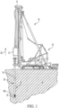
- a core barrel head assembly 100 for use with a drilling system 10 that includes a drill head 12.
- the drill head 12 can be coupled to a mast 14 that, in turn, is coupled to a drill rig 16.
- the drill head 12 can be configured to have one or more tubular threaded members 18 coupled thereto.
- Tubular members 18 can include, without limitation, drill rods, casings, and down-the-hole hammers.
- the tubular members 18 will be described herein as drill string components.
- the drill string component 18 can in turn be coupled to additional drill string components 18 to form a drill or tool string 20.
- the drill string 20 can be coupled at a distal end to a drilling tool 24, such as a rotary drill bit, a core sampling drill bit (e.g., an impregnated core sampling drill bit), or a percussive bit, configured to interface with the material, or formation 22, to be drilled.
- the drilling tool 24 can form a borehole 26 in the formation 22.
- the drilling tool 24 can further form a core sample that can be received within an inner tube assembly 90, comprising a core tube 130 and a core barrel head assembly 100, as further described herein.
- the core barrel head assembly 100 can comprise an indicator 302 that can be configured to detect a force applied to the core barrel assembly. The indicator can be used to determine whether the core barrel is full or whether the core is stuck within the core tube 130.
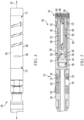
- the bearing housing 116 can further house a lower thrust bearing 122 configured to receive load during hoisting (or, optionally, a plurality of such bearings).
- the bearing housing 116 can comprise a grease port 124 for providing grease to the thrust bearings 120 and/or the lower thrust bearing 122.
- the thrust bearings 120 and lower thrust bearing 122 can each optionally be greaseless.
- the bearings 120 can be solid oil bearings. In this way, the grease port can be omitted, allowing for a longitudinally smaller configuration of the bearing housing 116, thereby allowing additional space for including other features (e.g., electronics or apertures 184).
- the thrust bearings 120 and lower thrust bearing 122 can rotationally engage a spindle 126.
- the distal end 112 of the elongate tube body 104 can define threads 132 for threadedly coupling to valve body 140.
- the valve body 140 can have a distal end 142, a proximal end 144, and an outer surface 146.
- the valve body 140 can define a valve seat 148 for engagement with a valve ball 150 to provide a check valve 152.
- the valve body 140 can define an interior cavity 154 having an interior surface 156.
- the interior cavity 154 can optionally be cylindrical.
- the valve body 140 can define female threads 158 at the distal end 142 for threadedly coupling to the core tube 130 ( FIG. 2 ).
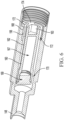
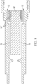
- An electronics compartment 160 having an outer surface 162 can be disposed at least partially within the interior cavity 154 of the valve body.
- the distal end 142 of the valve body 140 can define female threads 156 that can threadedly couple to male threads 168 on the outer surface 162 of the electronics compartment 160.
- the electronics compartment can define a hexagonal socket 163 that receives a hexagonal tool (e.g., an Allen key) for attaching to and removing the electronics compartment from the valve body.
- the electronics compartment 160 can define an interior volume 167 for housing a battery 164, an electronic orientation instrument 166, or both.
- the electronic orientation instrument 166 can comprise various sensors (e.g., accelerometers, magnetometers, gyroscopes, etc.) that can provide orientation data of the electronic orientation instrument and, accordingly, a core sample in the core tube 130.
- the internal volume 167 can be closed and sealed with a threaded cap 169.
- sensors in the electronic orientation instrument 166 can collect information related to hole survey data, hole geophysical data, hole visual data, hole depth, tooling valve status, and further data as is known in the art.
- the outer surface 162 of the electronics compartment 160 and the inner surface 156 of the interior cavity 154 can cooperate to define a fluid passage 170.
- the fluid passage 170 can optionally be annular.
- the fluid passage 170 can enable fluid to pass therethrough for various functions, including, for example, lubricating the drill bit during drilling.
- the electronics compartment 160 can comprise at least one opening 172 that provides fluid communication between the distal end of the electronics compartment 160 and the fluid passage 170.
- the electronics compartment 160 can comprise plurality of (e.g., two) annular section openings 172 separated by webs 174 that extend along the length of the threads 168.
- a valve body 140' and an electronics compartment 160' can cooperate to define the one or more openings 172'.
- the threaded portion of the electronics compartment can comprise a plurality (e.g., two or three) sections 176 having longitudinally extending gaps 178 therebetween.
- a valve body 140" can define the one or more openings 172" that provide fluid communication between the distal end of the electronics compartment 160" and the fluid passage 170.
- the thrust bearing can have a dynamic load of at least 8,500 lbf.
- conventional shut-off valves that detect when the core tube is full or jammed can be eliminated, and, instead, drill load sensing can be used to determine when the core tube is full or jammed.
- conventional core break springs and shut-off valve springs can be integrated into the body of the core barrel head assembly, as further disclosed herein.
- the elongate tube body 104 and valve body 140 can cooperate to serve as the indicator 302.
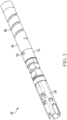
- the elongate tube body 104 can define at least one helical groove 180 that extends around the circumference of the elongate tube body 104 and along the longitudinal axis 102.
- helical should be understood to mean a path that wraps around the circumference and extends along the length of the elongate tube.
- the helical groove 180 as disclosed herein should be understood to include, for example, a groove having a continuous profile and a constant pitch (as shown), a groove having a varying pitch, and a stair step groove that alternatingly extends in a purely longitudinal direction for a segment and in a purely circumferential direction for another segment.
- the helical groove 180 can comprise a spiral shape having a constant pitch.
- the helical groove 180 can comprise about three revolutions around the circumference of the elongate tube body 104.
- the helical groove 180 can be about 0.889 cm (0.35 inches) wide and can have circular stress relief features at each end.
- the circular stress relief feature at the distal end of the helical groove 180 can be about 1.905 cm (0.75 inches) in diameter, and the stress relief feature at the proximal end of the helical groove 180 can be about 1.27 cm (0.5 inches) in diameter.
- the pitch of the groove can optionally be about 0.67 rotations per cm (1.7 rotations per inch). It should be understood that the disclosed dimensions are optional and that the dimensions can be selected to provide operative aspects as further disclosed herein.
- the helical groove 180 can enable the elongate tube body 104 to compress from a neutral length 190 (i.e., the length of the elongate tube when neither in compression nor tension, as shown in FIG. 10 ).
- the elongate tube body 104 can define one or more apertures 184 that extend between the outer surface 106 and the interior cavity 108.
- the elongate tube body 104 can define two slot-shaped apertures that are spaced 180 degrees about the circumference of the elongate tube body.
- the aperture(s) 184 can be elongated about the circumference of the elongate tube body.
- valve body 140 can cause a greater flow restriction through the aperture(s) 184 as the valve body moves proximally with respect to the proximal end of the elongate tube body 104.
- a pressure relief valve can regulate a maximum pressure.
- the pressure can rise beyond the set pressure of the pressure relief valve to thereby cause the valve to open and, thereby, indicate that the core tube is full. It is contemplated that the change in flow restriction can be reflected as a change in the percentage of the two-dimensional area of the aperture 184 that is blocked by the valve body 140.
- the change in the percentage of the area of the aperture that is blocked by the valve body can be at least 20%, at least 40%, at least 60%, at least 80%, at least 90 %, at least 95%, at least 99%, or, optionally, be about 100%. It is understood that the percentage change in blocked area should be sufficient to distinguish from minor variations in the relative positioning of the valve body that are not associated with proximal movement of the valve body for purposes of causing greater flow restriction.
- the change in flow restriction can correspond to a change in "blocked area" of the aperture of at least 0.064516 square centimeters (0.01 square inches), at least 0.32258 square centimeters (0.05 square inches), at least 0.64516 square centimeters (0.1 square inches), or at least 1.29032 square centimeters (0.2 square inches). It is understood that the change in blocked area should be sufficient to distinguish from minor variations in the relative positioning of the valve body that are not associated with proximal movement of the valve body for purposes of causing greater flow restriction.
- the greater flow restriction can correspond to a maximum pressure setting (as measured by the operator, such as with a pump). However, if the valve body 140 causes only a partial flow restriction, then the greater flow restriction can correspond to a pressure less than the maximum pressure setting.
- the changing flow restriction can cause the fluid pressure to change, and a drill operator can detect the change in fluid pressure.
- the change in fluid pressure can be at least 20%, at least 25%, at least 30%, at least 35%, at least 40%, at least 45%, or at least 50%.
- the change in fluid pressure can indicate to the drill operator that the core sample is jammed or that the core tube is full.
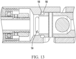
- the proximal end 144 of the valve body 140 can have a turned down (downwardly facing) portion that defines a shoulder 196.
- the interior surface of the elongate tube body 104 can define a complementary shoulder 198 that can act as a stop that engages the shoulder 196 of the valve body 140. In this way, the elongate tube body 104 can be limited to a minimum compressed length 192 ( FIG. 11 ).
- the aperture(s) 184 can have a cross sectional area (in the case of a plurality of apertures, a combined cross sectional area) in a radial dimension that is perpendicular to the longitudinal dimension, wherein the cross sectional area is selected to be at least as large as the minimum cross sectional area in the head assembly so that flow through the aperture does not increase flow restriction during drilling.
- the apertures provide transition porting from the head porting to the flow path 170, which provides a pressure drop, so an oversized aperture or oversized apertures can be beneficial in minimizing pressure drop along the core barrel head assembly 100.
- the size of the aperture(s) 184 in the longitudinal dimension 102 can be limited based on compressibility of the elongate tube body 104 or other such limits.
- the geometry and size of the aperture(s) can be limited in order to significantly restrict the flow through the aperture(s). Accordingly, in some embodiments, the size of the aperture(s) 184 in the longitudinal dimension 102 can be less than 0.635 cm (a quarter inch). or about 0.5588 cm (0.22 inches).
- the core barrel head assembly 100 can comprise a core lifter case 134 attached at a distal end of the core tube 130.
- a core lifter 136 can move within the core lifter case 134 to engage and grip the core sample during core break and core retrieval.
- a non-limiting example of a core lifter in accordance with embodiments disclosed herein is provided in U.S. Patent No. 8,770,320 to Drenth et al., issued July 8, 2014 .
- the core barrel head assembly 100 can be positioned at a distal end of the drill string 20 and engage the drill string via latches 210.
- the drill bit can be spaced from the core lifter case to provide a bit gap 212 that allows fluid to pass therethrough and lubricate the drill bit.
- core break the drill string is lifted until the bit gap is closed so that the bit can pull on the distal end of the core lifter case.
- Conventional core barrel head assemblies comprise a compressible core break spring that compresses to keep the core tube in a fixed longitudinal position so that the core tube does not move with respect to the core sample.
- the conventional core break spring can be eliminated, and the elongate tube body 104 can extend under tension from the neutral length 190 to an elongated length 194 ( FIG. 11 ) at which point the drill bit engages the core lifter.
- the elongate tube body 104 can replace the conventional core break spring. That is, as the drill string is retracted in the proximal direction 30 ( FIG. 1 ), the upper portion of the core barrel head assembly 100 rests on a landing ring of the drill string and, thus moves upward with the drill string.
- the elongate tube body 104 can elongate to a length at which the system is in a core break configuration in which the bit gap is closed and the drill bit engages the core lifter case.
- the various elongate tube bodies can optionally have apertures at various positions along their respective lengths.
- the material of the elongate tube body 104 can be selected to have an elastic modulus that provides significant and linear load response to small displacements.
- the material can optionally be traditional metals, or, in further embodiments, engineered amorphous metals, engineered composite metals, etc.
- the outer diameter of the elongate tube body 104, wall thickness, and the groove dimensions and geometry can be selected to provide a body having a desired spring constant while allowing for purely elastic deformation.
- the spring constant can be about 1,926.40 kN/m (11,110 lfb/in). for an NQ drill bit size.
- the spring constant can be selected based on the material of the formation (and the recovered core sample).
- the spring constant can be selected to allow compression and elongation for various materials.
- the spring constant can range from about 1,751.27 kN/m to 2,101.52 kN/m (10,000 Ibf/in to about 12,000 lbf/in).
- the at least one helical groove can comprise a plurality of grooves, such as, for example, dual grooves that are separated by 180 degrees about the circumference of the elongate tube body 104.
- a desirable spring constant can have a significant load resistance that allows the drill to push the sample tube through sticky/swelling clays or problematic ground conditions without compressing the elongate tube body 104 until the valve body 140 blocks or sufficiently blocks the aperture(s) 184, thereby falsely indicating that the core tube 130 is full.
- an operator can select from various elongate tube bodies 104 having various spring constants based on ground conditions.
- the elongate tube body 104 should be able to elastically extend the length of the bit gap. Moreover, the elongate tube body 104 must provide enough spring tension once extended to the elongated length 194 (when the drill bit engages the core lifter case) in order to allow the core lifter to seat in between the core sample and the core lifter case.
- the aperture 184 can be positioned along the length of the elongate tube body 104 so that, for the spring constant provided by the elongate tube body, a select force causes the valve body 140 to block the aperture 184.
- the spring force of the elongate tube body 104 when the elongate tube body is in the compressed configuration 194 can optionally match the spring constant of a compression spring used in conventional shut-off valves for detecting when the core sample is full.
- the valve body can block the valve aperture at a load that is similar to that of a conventional shut-off valve.
- conventional shut-off valves can close under a load of about 2500 lbf, although the load can vary depending on the size and configuration.
- a core bit can be used to collect a core sample is a hollow cylinder with a cutting surface on one face of the hollow cylinder.
- the core bit can be fixedly attached on one end of a cylindrical drill rod and inserted into a previously drilled bore hole. New sections of drill rods can be added to the upper end of the original rod, creating a series of connected drill rods in what is termed a drill string, as the core bit is pushed into the borehole. Each section of drill rod can be on the order of 3.048 m (10 feet) long.
- the core bit can be forced against a rock strata as the core bit is rotated by rotating the drill string. The combination of the force and the rotating cutting surface can cut a cylindrical core sample from the rock strata.
- Drilling fluid can be pumped into the borehole to cool and lubricate the drill bit.
- the drilling fluid can pass down the drill string and through a bit gap, as disclosed herein, between the core lifter case and the drill bit.
- the core sample can be captured in an interior portion of the drill string, within the core tube, behind the core bit until the core sample can be retrieved from the borehole.
- the length of an interior tube containing a core barrel is typically 1.524 m to 9.144 m (five feet to 30 feet) in length.
- the drill string can be retracted, thereby engaging the core lifter to seat between the core sample and the core lifter case. In doing so, the bit gap can close so that the drill bit biases against the core lifter case. As the drill string is further retracted, the engagement between the core lifter applies tension to the core, thereby causing a core break, whereby the core sample separates from the formation.
- the inner tube assembly with the core sample inside can be retrieved via wireline to retrieve the core sample from the bore.
- the core barrel head assembly 100 can have different spring rates for core break (spring tension) and for valve shutoff (blocking the apertures 184 in spring compression).
- valve shutoff can require substantially smaller forces than core break.
- the core barrel head assembly 100 can have a first spring rate in tension that is configured for spring break and a second spring rate in compression that is configured for allowing compression.
- this can be accomplished via compound springs.
- a second spring (not shown) can be configured to apply a spring force for only a portion of the travel between the proximal end 110 and the distal end 112 between the elongate length and the compressed length.
- Said second spring can optionally be a compression spring or a tension spring.
- the spring rate can be variable.
- the helical groove 180 that defines the spring can have a variable pitch. In this way, movement between the proximal end 110 and distal end 112 of the elongate tube body 104 can be subject to a nonlinear spring force between the elongate length and the compressed length.
- the core barrel head assembly 100 can comprise a conventional valve comprising a radially expandable valve ring to serve as the indicator 302.
- the lower core barrel may also comprise one or more compression washers that restrict the flow of drilling fluid once the core sample tube is full, or once a core sample is jammed in the core sample tube.
- the compression washers can be axially compressed when the drill string and the upper core barrel press in the drilling direction, but the core sample tube does not move axially because the sample tube is full or otherwise prevented from moving downwardly with the drill string.
- the indicator 302 of the core barrel head assembly 100 can optionally comprise or be a load cell that is configured to measure axial force on the core tube.
- the load cell can serve as the indicator 302.
- the load cell can be in communication with a computing device via conventional communication means for providing feedback to an operator.
- the measured axial force can indicate that the core sample is stuck/jammed within the core tube.
- the measured axial force can indicate that the core barrel is full.
- the disclosed core barrel assemblies can comprise latch mechanisms and latch-seat features as are known in the art.
- the latch mechanisms and latch-seat features can have significant tolerance and axial movement such that, during a core block or jamming event, the landing shoulder of the head assembly can lift off of the mating landing ring in the outer tube assembly and provide fluid bypass, thereby causing a fluid pressure drop that can serve as an indication of a core jamming in the core tube.
- the head assembly can comprise a latch mechanism 300 that is configured to engage the inner wall of the drill string to retain the head assembly 100 in position relative to the longitudinal axis of the drill string.
- the latch mechanism 300 can comprise latch body 304 that defines a plurality of through holes 306 that receive respective wedge members 308.
- the latch mechanism can further comprise a proximal body 310 that is receivable into the latch body and is axially movable relative to the latch body.
- the proximal body can comprise a circumferential surface 312 that defines one or more wedge surfaces 314 that are configured to drive the respective wedge members outwardly through the respective through-holes in the latch body when the proximal body is in a first axial position ( FIG. 16 ) relative to the latch body.
- the wedge members 308 can be balls, rollers, cams, or other suitable members that are configured to wedge against the inner walls of the drill string.
- the proximal body can be configured to couple to a wireline (e.g., via a conventional spearhead coupling) to thereby receive a proximal force.
- the proximal force can move the proximal body 310 to a second axial position ( FIG. 17 ) relative to the latch body 304.
- the circumferential surface 312 of the proximal body can define a radially recessed portion 318 that allows the wedge members 308 to move radially inwardly to disengage from the inner surface of the drill string, thereby allowing the head assembly to move relative to the drill string.
- a detent can retain the proximal body in its first and second positions.
- an inner extension 320 can be fixedly coupled to the latch body (e.g., via a spring pin coupling) so that the inner extension cannot move axially relative to the latch body.
- the inner extension can define a groove that can receive a canted-coil spring 326.
- the proximal body can define a first shoulder 322 and a second shoulder 324 that are axially spaced from each other.
- the canted coil spring 326 can engage the first and second shoulders when the proximal body is in the first and second position, respectively, to serve as a detent to retain the proximal body in each position.
- the canted coil spring when the proximal body is in the first position, canted coil spring can bias against the first shoulder when to inhibit movement of the proximal body toward the second position.
- the canted coil spring can bias against the second shoulder to inhibit movement of the proximal body toward the first position.
Landscapes
- Engineering & Computer Science (AREA)
- Geology (AREA)
- Life Sciences & Earth Sciences (AREA)
- Mining & Mineral Resources (AREA)
- Physics & Mathematics (AREA)
- Environmental & Geological Engineering (AREA)
- Fluid Mechanics (AREA)
- General Life Sciences & Earth Sciences (AREA)
- Geochemistry & Mineralogy (AREA)
- Geophysics (AREA)
- Acoustics & Sound (AREA)
- Remote Sensing (AREA)
- Sampling And Sample Adjustment (AREA)
- Infusion, Injection, And Reservoir Apparatuses (AREA)
Claims (15)
- Eine Kernrohrkopfanordnung (100) mit einer Längsachse (102), wobei die Kernrohrkopfanordnung Folgendes umfasst:einen länglichen Rohrkörper (104) mit einer Außenfläche (106), einem Innenhohlraum (108), einem proximalen Ende (110) und einem distalen Ende (112), dadurch gekennzeichnet, dass der längliche Rohrkörper eine spiralförmige Nut (180) definiert, die sich vom Innenhohlraum zur Außenfläche des länglichen Rohrkörpers erstreckt, wobei die spiralförmige Nut so konfiguriert ist, dass sich der längliche Rohrkörper elastisch von einer neutralen Länge (190) auf eine verlängerte Länge (194) ausdehnen kann, und wobei die spiralförmige Nut so konfiguriert ist, dass sich der längliche Rohrkörper elastisch von der neutralen Länge zusammendrücken kann, undeinen Ventilkörper (140), der an dem länglichen Rohrkörper angebracht ist und in Bezug auf das proximale Ende des länglichen Rohrkörpers entlang der Längsachse von einer ersten Position in eine zweite Position beweglich ist, wenn der längliche Rohrkörper komprimiert wird.
- Die Kernrohrkopfanordnung nach Anspruch 1, wobei der längliche Rohrkörper mindestens eine Öffnung (184) definiert, die sich zwischen dem Innenhohlraum und der Außenfläche erstreckt, wobei, wenn sich der längliche Rohrkörper in der zweiten Position befindet, der Ventilkörper eine größere Einschränkung des Durchflusses durch die mindestens eine Öffnung bewirkt, als wenn sich der Ventilkörper in der ersten Position befindet.
- Die Kernrohrkopfanordnung nach Anspruch 2, wobei die mindestens eine Öffnung einen Gesamtdurchflussbereich von weniger als 3,2258 Quadratzentimetern (0,5 Quadratzoll) definiert.
- Die Kernrohrkopfanordnung nach Anspruch 3, wobei die mindestens eine Öffnung eine Breitenabmessung entlang der Längsachse aufweist, die weniger als 0,635 cm (0,25 Zoll) beträgt.
- Die Kernrohrkopfanordnung nach Anspruch 2, die außerdem ein Elektronikfach (160) mit einer Außenfläche (162) umfasst, wobei der Ventilkörper einen Innenhohlraum (154) definiert, wobei das Elektronikfach innerhalb des Innenhohlraums des Ventilkörpers angeordnet ist, wobei das Elektronikfach am Ventilkörper angebracht ist, so dass die Innenfläche des Innenhohlraums des Ventilkörpers und die Außenfläche des Elektronikfachs einen Flüssigkeitsdurchgang (170) definieren, wobei der Ventilkörper, das Elektronikfach oder eine Kombination aus mindestens einer Innenfläche (156) des Ventilkörpers und mindestens einer Außenfläche des Elektronikfachs mindestens eine Öffnung definiert, um eine Flüssigkeitskommunikation zwischen dem Flüssigkeitsdurchgang und dem distalen Ende (142) des Ventilkörpers bereitzustellen.
- Die Kernrohrkopfanordnung nach Anspruch 5, wobei das Elektronikfach mindestens eine Batterie (164) oder ein elektronisches Orientierungsinstrument (166) beherbergt.
- Die Kernrohrkopfanordnung nach Anspruch 5, wobei der Flüssigkeitsdurchgang, der durch die Innenfläche des Innenhohlraums des Ventilkörpers und die Außenfläche des Elektronikfachs definiert wird, ein ringförmiger Hohlraum ist.
- Die Kernrohrkopfanordnung nach Anspruch 5, wobei das Elektronikfach mindestens eine Öffnung (177) zur Herstellung einer Flüssigkeitsverbindung zwischen dem Flüssigkeitsdurchgang und dem distalen Ende des Ventilkörpers aufweist.
- Die Kernrohrkopfanordnung nach Anspruch 8, wobei ein Teil der Außenfläche des Elektronikfachs mindestens ein Außengewinde (168) entlang einer Gewindelänge aufweist, wobei die Innenfläche des Ventilkörpers mindestens ein entsprechendes Innengewinde (156) aufweist, wobei das Elektronikfach über das mindestens eine Außengewinde und das mindestens eine entsprechende Innengewinde mit dem Ventilkörper verschraubt ist, wobei sich die mindestens eine Öffnung entlang der Gewindelänge durch das Elektronikfach erstreckt.
- Die Kernrohrkopfanordnung nach Anspruch 8, wobei die mindestens eine Öffnung eine Vielzahl von Öffnungen umfasst, die durch entsprechende radial verlaufende Stege (174) getrennt sind.
- Die Kernrohrkopfanordnung nach Anspruch 5, wobei der Ventilkörper die mindestens eine Öffnung definiert, um eine Flüssigkeitsverbindung zwischen dem Flüssigkeitsdurchgang und dem distalen Ende des Ventilkörpers bereitzustellen.
- Die Kernrohrkopfanordnung nach Anspruch 5, wobei die Kombination aus mindestens einer Innenfläche des Ventilkörpers und mindestens einer Außenfläche des Elektronikfachs die mindestens eine Öffnung definiert, um eine Flüssigkeitsverbindung zwischen dem Flüssigkeitsdurchgang und dem distalen Ende des Ventilkörpers bereitzustellen.
- Die Kernrohrkopfanordnung nach Anspruch 1, wobei die Kernrohrkopfanordnung ein einzelnes Axiallager (122) umfasst.
- Die Kernrohrkopfanordnung nach Anspruch 1, wobei die Kernrohrkopfanordnung keinen Schmieranschluss (124) umfasst.
- Ein Bohrsystem, das Folgendes umfasst:ein Bohrgestänge (20) mit:einem Bohrmeißel (24) an einem distalen Ende des Bohrgestänges;eine Kernrohrkopfanordnung nach einem der Ansprüche 1-14, wobei die Kernrohrkopfanordnung ein distales Ende hat, undeine Kernrohranordnung (130), die an der Kernrohrkopfanordnung angebracht ist, wobei die Kernrohranordnung Folgendes umfasst:ein Kernrohr mit einem distalen Ende undein Kernhebergehäuse (134) am distalen Ende des Kernrohrs;wobei, wenn sich der Bohrer in einer Bohrkonfiguration befindet, der Bohrer distal vom Kernhebergehäuse beabstandet ist, undwobei, wenn sich der Bohrer in einer Kernbrechkonfiguration befindet, der Bohrer mit dem Kernhebergehäuse in Kontakt ist und der längliche Rohrkörper von der neutralen Länge aus verlängert ist.
Priority Applications (1)
| Application Number | Priority Date | Filing Date | Title |
|---|---|---|---|
| EP24204399.0A EP4506534A3 (de) | 2019-10-17 | 2020-10-16 | Kopfanordnung eines kernrohrs |
Applications Claiming Priority (2)
| Application Number | Priority Date | Filing Date | Title |
|---|---|---|---|
| US201962916585P | 2019-10-17 | 2019-10-17 | |
| PCT/US2020/055913 WO2021076844A1 (en) | 2019-10-17 | 2020-10-16 | Core barrel head assembly |
Related Child Applications (2)
| Application Number | Title | Priority Date | Filing Date |
|---|---|---|---|
| EP24204399.0A Division EP4506534A3 (de) | 2019-10-17 | 2020-10-16 | Kopfanordnung eines kernrohrs |
| EP24204399.0A Division-Into EP4506534A3 (de) | 2019-10-17 | 2020-10-16 | Kopfanordnung eines kernrohrs |
Publications (3)
| Publication Number | Publication Date |
|---|---|
| EP4045761A1 EP4045761A1 (de) | 2022-08-24 |
| EP4045761A4 EP4045761A4 (de) | 2023-10-11 |
| EP4045761B1 true EP4045761B1 (de) | 2024-11-20 |
Family
ID=75538635
Family Applications (2)
| Application Number | Title | Priority Date | Filing Date |
|---|---|---|---|
| EP24204399.0A Withdrawn EP4506534A3 (de) | 2019-10-17 | 2020-10-16 | Kopfanordnung eines kernrohrs |
| EP20876135.3A Active EP4045761B1 (de) | 2019-10-17 | 2020-10-16 | Kopfanordnung eines kernrohrs |
Family Applications Before (1)
| Application Number | Title | Priority Date | Filing Date |
|---|---|---|---|
| EP24204399.0A Withdrawn EP4506534A3 (de) | 2019-10-17 | 2020-10-16 | Kopfanordnung eines kernrohrs |
Country Status (9)
| Country | Link |
|---|---|
| US (2) | US12134953B2 (de) |
| EP (2) | EP4506534A3 (de) |
| AU (1) | AU2020368461A1 (de) |
| CA (1) | CA3158024A1 (de) |
| CL (2) | CL2022000975A1 (de) |
| ES (1) | ES3004872T3 (de) |
| FI (1) | FI4045761T3 (de) |
| PE (1) | PE20221029A1 (de) |
| WO (1) | WO2021076844A1 (de) |
Families Citing this family (2)
| Publication number | Priority date | Publication date | Assignee | Title |
|---|---|---|---|---|
| AU2021107115A4 (en) * | 2019-10-17 | 2021-12-02 | Boart Longyear Manufacturing And Distribution Inc. | Greaseless core barrel head assembly |
| WO2023173030A1 (en) | 2022-03-11 | 2023-09-14 | Axis Service, Llc | Pressure control assembly |
Family Cites Families (19)
| Publication number | Priority date | Publication date | Assignee | Title |
|---|---|---|---|---|
| US2532716A (en) * | 1947-11-28 | 1950-12-05 | Gerben Meidema | Double tube core barrel for core drilling |
| US3225845A (en) * | 1961-02-17 | 1965-12-28 | Joy Mfg Co | Core barrel assembly |
| US3871487A (en) * | 1974-02-25 | 1975-03-18 | Longyear Co | Wire line soil sampler apparatus |
| NO316886B1 (no) * | 1996-10-17 | 2004-06-14 | Baker Hughes Inc | Undergrunnsformasjon-boreapparat samt fremgangsmate for boring av en undergrunnsformasjon |
| US6216804B1 (en) * | 1998-07-29 | 2001-04-17 | James T. Aumann | Apparatus for recovering core samples under pressure |
| US6719070B1 (en) * | 2000-11-14 | 2004-04-13 | Baker Hughes Incorporated | Apparatus and methods for sponge coring |
| US6425449B1 (en) * | 2001-02-08 | 2002-07-30 | Boart Longyear International Holdings, Inc. | Up-hole pump-in core barrel apparatus |
| US9359847B2 (en) * | 2007-03-03 | 2016-06-07 | Longyear Tm, Inc. | High productivity core drilling system |
| WO2010091471A1 (en) * | 2009-02-12 | 2010-08-19 | Imdex Technology Australia Pty Ltd | Downhole tool housing |
| US9399898B2 (en) * | 2009-10-07 | 2016-07-26 | Longyear Tm, Inc. | Core drilling tools with retractably lockable driven latch mechanisms |
| US8770320B2 (en) | 2009-11-03 | 2014-07-08 | Longyear Tm, Inc. | Core lifter |
| US9132968B2 (en) * | 2011-11-04 | 2015-09-15 | Mark E. Koenig | Cantilevered screw assembly |
| WO2015031475A1 (en) | 2013-08-27 | 2015-03-05 | Baker Hughes Incorporated | Mechanical core jam indicator for coring tools, coring tools including such core jam indicators, and related methods |
| CN107109899B (zh) * | 2014-04-21 | 2020-09-04 | 长年Tm公司 | 具有集成的样本定向工具的岩心筒头组件及使用该组件的系统 |
| US10577880B2 (en) * | 2014-10-10 | 2020-03-03 | Specialised Oilfield Services Pty Ltd | Device and system for use in monitoring coring operations |
| US10385640B2 (en) * | 2017-01-10 | 2019-08-20 | Weatherford Technology Holdings, Llc | Tension cutting casing and wellhead retrieval system |
| US10975683B2 (en) * | 2018-02-08 | 2021-04-13 | Baker Hughes Holdings Llc | Coring tools enabling measurement of dynamic responses of inner barrels and related methods |
| US10954736B2 (en) * | 2018-03-16 | 2021-03-23 | Weatherford Technology Holdings, Llc | Downhole casing pulling tool |
| CN109458147B (zh) * | 2018-11-08 | 2020-07-07 | 深圳大学 | 取芯装置 |
-
2020
- 2020-10-16 AU AU2020368461A patent/AU2020368461A1/en active Pending
- 2020-10-16 US US17/768,617 patent/US12134953B2/en active Active
- 2020-10-16 ES ES20876135T patent/ES3004872T3/es active Active
- 2020-10-16 CA CA3158024A patent/CA3158024A1/en active Pending
- 2020-10-16 FI FIEP20876135.3T patent/FI4045761T3/fi active
- 2020-10-16 PE PE2022000637A patent/PE20221029A1/es unknown
- 2020-10-16 EP EP24204399.0A patent/EP4506534A3/de not_active Withdrawn
- 2020-10-16 EP EP20876135.3A patent/EP4045761B1/de active Active
- 2020-10-16 WO PCT/US2020/055913 patent/WO2021076844A1/en not_active Ceased
-
2022
- 2022-04-18 CL CL2022000975A patent/CL2022000975A1/es unknown
-
2024
- 2024-04-12 CL CL2024001158A patent/CL2024001158A1/es unknown
- 2024-10-07 US US18/908,426 patent/US20250027384A1/en active Pending
Also Published As
| Publication number | Publication date |
|---|---|
| PE20221029A1 (es) | 2022-06-16 |
| ES3004872T3 (en) | 2025-03-13 |
| US20250027384A1 (en) | 2025-01-23 |
| US12134953B2 (en) | 2024-11-05 |
| WO2021076844A1 (en) | 2021-04-22 |
| EP4045761A4 (de) | 2023-10-11 |
| CL2024001158A1 (es) | 2024-09-27 |
| US20240102356A1 (en) | 2024-03-28 |
| EP4506534A3 (de) | 2025-03-19 |
| CL2022000975A1 (es) | 2022-11-25 |
| CA3158024A1 (en) | 2021-04-22 |
| FI4045761T3 (fi) | 2025-02-25 |
| EP4506534A2 (de) | 2025-02-12 |
| AU2020368461A1 (en) | 2022-05-26 |
| EP4045761A1 (de) | 2022-08-24 |
Similar Documents
| Publication | Publication Date | Title |
|---|---|---|
| US20250027384A1 (en) | Core Barrel Head Assembly | |
| US20250075576A1 (en) | Greaseless core barrel head assembly | |
| US8869918B2 (en) | Core drilling tools with external fluid pathways | |
| US8485280B2 (en) | Core drilling tools with retractably lockable driven latch mechanisms | |
| CA1041989A (en) | Apparatus for providing a packaged core | |
| US9528337B2 (en) | Up-hole bushing and core barrel head assembly comprising same | |
| US9708874B2 (en) | Mechanical core jam indicator for coring tools, coring tools including such core jam indicators, and related methods | |
| US8550160B2 (en) | Apparatus and methods for pulse testing a formation | |
| US20130105227A1 (en) | High productivity core drilling system | |
| US9399898B2 (en) | Core drilling tools with retractably lockable driven latch mechanisms | |
| WO2019239100A1 (en) | Improvements in or relating to well abandonment and slot recovery | |
| US3804185A (en) | Jarring and bumping tool for use in oilfield drilling strings | |
| EP4237656B1 (de) | Vorrichtungen und verfahren zur verwendung mit umkehrkreislaufüberschusssystemen | |
| WO2015130396A1 (en) | Core drilling tools with retractably lockable driven latch mechanisms |
Legal Events
| Date | Code | Title | Description |
|---|---|---|---|
| STAA | Information on the status of an ep patent application or granted ep patent |
Free format text: STATUS: THE INTERNATIONAL PUBLICATION HAS BEEN MADE |
|
| PUAI | Public reference made under article 153(3) epc to a published international application that has entered the european phase |
Free format text: ORIGINAL CODE: 0009012 |
|
| STAA | Information on the status of an ep patent application or granted ep patent |
Free format text: STATUS: REQUEST FOR EXAMINATION WAS MADE |
|
| 17P | Request for examination filed |
Effective date: 20220505 |
|
| AK | Designated contracting states |
Kind code of ref document: A1 Designated state(s): AL AT BE BG CH CY CZ DE DK EE ES FI FR GB GR HR HU IE IS IT LI LT LU LV MC MK MT NL NO PL PT RO RS SE SI SK SM TR |
|
| DAV | Request for validation of the european patent (deleted) | ||
| DAX | Request for extension of the european patent (deleted) | ||
| P01 | Opt-out of the competence of the unified patent court (upc) registered |
Effective date: 20230523 |
|
| A4 | Supplementary search report drawn up and despatched |
Effective date: 20230908 |
|
| RIC1 | Information provided on ipc code assigned before grant |
Ipc: E21B 25/02 20060101ALI20230904BHEP Ipc: E21B 47/24 20120101ALI20230904BHEP Ipc: E21B 47/017 20120101ALI20230904BHEP Ipc: E21B 44/06 20060101ALI20230904BHEP Ipc: E21B 34/08 20060101ALI20230904BHEP Ipc: E21B 49/02 20060101ALI20230904BHEP Ipc: E21B 25/04 20060101ALI20230904BHEP Ipc: E21B 25/16 20060101AFI20230904BHEP |
|
| RAP1 | Party data changed (applicant data changed or rights of an application transferred) |
Owner name: BOART LONGYEAR COMPANY |
|
| GRAP | Despatch of communication of intention to grant a patent |
Free format text: ORIGINAL CODE: EPIDOSNIGR1 |
|
| STAA | Information on the status of an ep patent application or granted ep patent |
Free format text: STATUS: GRANT OF PATENT IS INTENDED |
|
| INTG | Intention to grant announced |
Effective date: 20240612 |
|
| GRAS | Grant fee paid |
Free format text: ORIGINAL CODE: EPIDOSNIGR3 |
|
| GRAA | (expected) grant |
Free format text: ORIGINAL CODE: 0009210 |
|
| STAA | Information on the status of an ep patent application or granted ep patent |
Free format text: STATUS: THE PATENT HAS BEEN GRANTED |
|
| RAP1 | Party data changed (applicant data changed or rights of an application transferred) |
Owner name: VERACIO LTD. |
|
| AK | Designated contracting states |
Kind code of ref document: B1 Designated state(s): AL AT BE BG CH CY CZ DE DK EE ES FI FR GB GR HR HU IE IS IT LI LT LU LV MC MK MT NL NO PL PT RO RS SE SI SK SM TR |
|
| REG | Reference to a national code |
Ref country code: GB Ref legal event code: FG4D |
|
| REG | Reference to a national code |
Ref country code: CH Ref legal event code: EP |
|
| REG | Reference to a national code |
Ref country code: DE Ref legal event code: R096 Ref document number: 602020041845 Country of ref document: DE |
|
| REG | Reference to a national code |
Ref country code: IE Ref legal event code: FG4D |
|
| REG | Reference to a national code |
Ref country code: SE Ref legal event code: TRGR |
|
| REG | Reference to a national code |
Ref country code: FI Ref legal event code: FGE |
|
| REG | Reference to a national code |
Ref country code: ES Ref legal event code: FG2A Ref document number: 3004872 Country of ref document: ES Kind code of ref document: T3 Effective date: 20250313 |
|
| REG | Reference to a national code |
Ref country code: LT Ref legal event code: MG9D |
|
| REG | Reference to a national code |
Ref country code: NL Ref legal event code: MP Effective date: 20241120 |
|
| PG25 | Lapsed in a contracting state [announced via postgrant information from national office to epo] |
Ref country code: PT Free format text: LAPSE BECAUSE OF FAILURE TO SUBMIT A TRANSLATION OF THE DESCRIPTION OR TO PAY THE FEE WITHIN THE PRESCRIBED TIME-LIMIT Effective date: 20250320 Ref country code: IS Free format text: LAPSE BECAUSE OF FAILURE TO SUBMIT A TRANSLATION OF THE DESCRIPTION OR TO PAY THE FEE WITHIN THE PRESCRIBED TIME-LIMIT Effective date: 20250320 Ref country code: HR Free format text: LAPSE BECAUSE OF FAILURE TO SUBMIT A TRANSLATION OF THE DESCRIPTION OR TO PAY THE FEE WITHIN THE PRESCRIBED TIME-LIMIT Effective date: 20241120 |
|
| PG25 | Lapsed in a contracting state [announced via postgrant information from national office to epo] |
Ref country code: NL Free format text: LAPSE BECAUSE OF FAILURE TO SUBMIT A TRANSLATION OF THE DESCRIPTION OR TO PAY THE FEE WITHIN THE PRESCRIBED TIME-LIMIT Effective date: 20241120 |
|
| REG | Reference to a national code |
Ref country code: AT Ref legal event code: MK05 Ref document number: 1743721 Country of ref document: AT Kind code of ref document: T Effective date: 20241120 |
|
| PG25 | Lapsed in a contracting state [announced via postgrant information from national office to epo] |
Ref country code: BG Free format text: LAPSE BECAUSE OF FAILURE TO SUBMIT A TRANSLATION OF THE DESCRIPTION OR TO PAY THE FEE WITHIN THE PRESCRIBED TIME-LIMIT Effective date: 20241120 |
|
| PG25 | Lapsed in a contracting state [announced via postgrant information from national office to epo] |
Ref country code: GR Free format text: LAPSE BECAUSE OF FAILURE TO SUBMIT A TRANSLATION OF THE DESCRIPTION OR TO PAY THE FEE WITHIN THE PRESCRIBED TIME-LIMIT Effective date: 20250221 Ref country code: AT Free format text: LAPSE BECAUSE OF FAILURE TO SUBMIT A TRANSLATION OF THE DESCRIPTION OR TO PAY THE FEE WITHIN THE PRESCRIBED TIME-LIMIT Effective date: 20241120 Ref country code: LV Free format text: LAPSE BECAUSE OF FAILURE TO SUBMIT A TRANSLATION OF THE DESCRIPTION OR TO PAY THE FEE WITHIN THE PRESCRIBED TIME-LIMIT Effective date: 20241120 |
|
| PG25 | Lapsed in a contracting state [announced via postgrant information from national office to epo] |
Ref country code: PL Free format text: LAPSE BECAUSE OF FAILURE TO SUBMIT A TRANSLATION OF THE DESCRIPTION OR TO PAY THE FEE WITHIN THE PRESCRIBED TIME-LIMIT Effective date: 20241120 |
|
| PG25 | Lapsed in a contracting state [announced via postgrant information from national office to epo] |
Ref country code: RS Free format text: LAPSE BECAUSE OF FAILURE TO SUBMIT A TRANSLATION OF THE DESCRIPTION OR TO PAY THE FEE WITHIN THE PRESCRIBED TIME-LIMIT Effective date: 20250220 |
|
| PG25 | Lapsed in a contracting state [announced via postgrant information from national office to epo] |
Ref country code: SM Free format text: LAPSE BECAUSE OF FAILURE TO SUBMIT A TRANSLATION OF THE DESCRIPTION OR TO PAY THE FEE WITHIN THE PRESCRIBED TIME-LIMIT Effective date: 20241120 |
|
| PG25 | Lapsed in a contracting state [announced via postgrant information from national office to epo] |
Ref country code: DK Free format text: LAPSE BECAUSE OF FAILURE TO SUBMIT A TRANSLATION OF THE DESCRIPTION OR TO PAY THE FEE WITHIN THE PRESCRIBED TIME-LIMIT Effective date: 20241120 |
|
| PG25 | Lapsed in a contracting state [announced via postgrant information from national office to epo] |
Ref country code: EE Free format text: LAPSE BECAUSE OF FAILURE TO SUBMIT A TRANSLATION OF THE DESCRIPTION OR TO PAY THE FEE WITHIN THE PRESCRIBED TIME-LIMIT Effective date: 20241120 |
|
| PG25 | Lapsed in a contracting state [announced via postgrant information from national office to epo] |
Ref country code: RO Free format text: LAPSE BECAUSE OF FAILURE TO SUBMIT A TRANSLATION OF THE DESCRIPTION OR TO PAY THE FEE WITHIN THE PRESCRIBED TIME-LIMIT Effective date: 20241120 |
|
| PG25 | Lapsed in a contracting state [announced via postgrant information from national office to epo] |
Ref country code: SK Free format text: LAPSE BECAUSE OF FAILURE TO SUBMIT A TRANSLATION OF THE DESCRIPTION OR TO PAY THE FEE WITHIN THE PRESCRIBED TIME-LIMIT Effective date: 20241120 |
|
| PG25 | Lapsed in a contracting state [announced via postgrant information from national office to epo] |
Ref country code: CZ Free format text: LAPSE BECAUSE OF FAILURE TO SUBMIT A TRANSLATION OF THE DESCRIPTION OR TO PAY THE FEE WITHIN THE PRESCRIBED TIME-LIMIT Effective date: 20241120 |
|
| PG25 | Lapsed in a contracting state [announced via postgrant information from national office to epo] |
Ref country code: IT Free format text: LAPSE BECAUSE OF FAILURE TO SUBMIT A TRANSLATION OF THE DESCRIPTION OR TO PAY THE FEE WITHIN THE PRESCRIBED TIME-LIMIT Effective date: 20241120 |
|
| REG | Reference to a national code |
Ref country code: DE Ref legal event code: R097 Ref document number: 602020041845 Country of ref document: DE |
|
| PLBE | No opposition filed within time limit |
Free format text: ORIGINAL CODE: 0009261 |
|
| STAA | Information on the status of an ep patent application or granted ep patent |
Free format text: STATUS: NO OPPOSITION FILED WITHIN TIME LIMIT |
|
| 26N | No opposition filed |
Effective date: 20250821 |
|
| PGFP | Annual fee paid to national office [announced via postgrant information from national office to epo] |
Ref country code: GB Payment date: 20260121 Year of fee payment: 6 |