EP4045797B1 - Nacelle destinée à une éolienne - Google Patents
Nacelle destinée à une éolienne Download PDFInfo
- Publication number
- EP4045797B1 EP4045797B1 EP20807369.2A EP20807369A EP4045797B1 EP 4045797 B1 EP4045797 B1 EP 4045797B1 EP 20807369 A EP20807369 A EP 20807369A EP 4045797 B1 EP4045797 B1 EP 4045797B1
- Authority
- EP
- European Patent Office
- Prior art keywords
- housing
- nacelle
- load
- sidewalls
- frame
- Prior art date
- Legal status (The legal status is an assumption and is not a legal conclusion. Google has not performed a legal analysis and makes no representation as to the accuracy of the status listed.)
- Active
Links
Images


Classifications
-
- F—MECHANICAL ENGINEERING; LIGHTING; HEATING; WEAPONS; BLASTING
- F03—MACHINES OR ENGINES FOR LIQUIDS; WIND, SPRING, OR WEIGHT MOTORS; PRODUCING MECHANICAL POWER OR A REACTIVE PROPULSIVE THRUST, NOT OTHERWISE PROVIDED FOR
- F03D—WIND MOTORS
- F03D80/00—Details, components or accessories not provided for in groups F03D1/00 - F03D17/00
- F03D80/80—Arrangement of components within nacelles or towers
- F03D80/82—Arrangement of components within nacelles or towers of electrical components
-
- F—MECHANICAL ENGINEERING; LIGHTING; HEATING; WEAPONS; BLASTING
- F03—MACHINES OR ENGINES FOR LIQUIDS; WIND, SPRING, OR WEIGHT MOTORS; PRODUCING MECHANICAL POWER OR A REACTIVE PROPULSIVE THRUST, NOT OTHERWISE PROVIDED FOR
- F03D—WIND MOTORS
- F03D80/00—Details, components or accessories not provided for in groups F03D1/00 - F03D17/00
- F03D80/80—Arrangement of components within nacelles or towers
- F03D80/88—Arrangement of components within nacelles or towers of mechanical components
-
- F—MECHANICAL ENGINEERING; LIGHTING; HEATING; WEAPONS; BLASTING
- F05—INDEXING SCHEMES RELATING TO ENGINES OR PUMPS IN VARIOUS SUBCLASSES OF CLASSES F01-F04
- F05B—INDEXING SCHEME RELATING TO WIND, SPRING, WEIGHT, INERTIA OR LIKE MOTORS, TO MACHINES OR ENGINES FOR LIQUIDS COVERED BY SUBCLASSES F03B, F03D AND F03G
- F05B2240/00—Components
- F05B2240/10—Stators
- F05B2240/14—Casings, housings, nacelles, gondels or the like, protecting or supporting assemblies there within
-
- Y—GENERAL TAGGING OF NEW TECHNOLOGICAL DEVELOPMENTS; GENERAL TAGGING OF CROSS-SECTIONAL TECHNOLOGIES SPANNING OVER SEVERAL SECTIONS OF THE IPC; TECHNICAL SUBJECTS COVERED BY FORMER USPC CROSS-REFERENCE ART COLLECTIONS [XRACs] AND DIGESTS
- Y02—TECHNOLOGIES OR APPLICATIONS FOR MITIGATION OR ADAPTATION AGAINST CLIMATE CHANGE
- Y02E—REDUCTION OF GREENHOUSE GAS [GHG] EMISSIONS, RELATED TO ENERGY GENERATION, TRANSMISSION OR DISTRIBUTION
- Y02E10/00—Energy generation through renewable energy sources
- Y02E10/70—Wind energy
- Y02E10/72—Wind turbines with rotation axis in wind direction
Definitions
- the present invention relates to a nacelle for a wind turbine.
- a wind turbine converts the kinetic energy in the wind into mechanical power by means of a rotor coupled to main machinery components.
- Wind turbines comes in various sizes ranging from small wind turbines to very large turbines, the majority of which are large threebladed horizontal-axis wind turbines (HAWT).
- the large wind turbines are high and have a very large numbers of main machinery component groups and subcomponents installed on a frame inside the nacelle cover.
- Wind turbines from different manufacturers have different frames and arrangements of machinery to fit inside the various designs of composite nacelle cover, which designs have an impact on the arrangement of the machinery as well.
- the load-carrying frame typically consists of a rear frame part, a front frame part, and optionally a generator frame part, which frame parts are installed in the nacelle cover to carry and support many of the components and machinery that transform the wind's kinetic energy conferred to the rotor into mechanical energy to turn a generator that produces electric power.
- the components and machinery are hitherto installed on the load-carrying frame, which is then lifted into the nacelle cover, secured to the nacelle cover and aligned with the rotor to be put in operative condition to gain electric power.
- the front frame part and the optional general frame part may be referred to as the bed plate frame and the rear frame part may be referred to as the main frame.
- EP-A-3247899 discloses a wind turbine nacelle configured for mounting on a wind turbine tower and for supporting a rotor assembly, the nacelle comprising at least a first and a second nacelle module.
- the first nacelle module comprises a first frame structure and a main bearing system for a main shaft of the rotor assembly
- the second nacelle module comprises a second frame structure and a drive train system for the wind turbine.
- first frame structure is configured to support the main bearing system during transportation and prior to mounting of the nacelle
- second frame structure is configured to support the drive train system during transportation and prior to mounting of the nacelle
- first and second frame structures form a load carrying structure of a first and a second shipping freight container such that the first and second nacelle module can be transported as shipping freight containers.
- first and second frame structures may be placed side by side in a direction along a rotational axis of the wind turbine rotor and may be oriented such as to have a length extending transversely to a rotational axis of the wind turbine rotor.
- US-A-2005/230979 discloses a wind turbine is provided that minimizes the size of the drive train and nacelle while maintaining the power electronics and transformer at the top of the tower.
- the turbine includes a direct drive generator having an integrated disk brake positioned radially inside the stator while minimizing the potential for contamination.
- the turbine further includes a means for mounting a transformer below the nacelle within the tower.
- the hub is secured to the front of the nacelle cover with the blades directly bolted to the hub, or bolted to the hub via a pitch bearing.
- the yaw system, mainshaft bearing, gearbox, generator, transformer and electrical control cabinets are behind the hub and conventionally mounted on the front frame of the nacelle.
- the load-carrying frame can e.g. be made as two heavy main cast and/or welded steel parts, wherein e.g. the yaw system, main shaft, and optionally the gearbox, are secured to the front frame part, and the transformer, and electrical cabinets are secured to the rear frame part.
- the generator can conventionally be secured to any of the front frame part and the rear frame part.
- EP-A-2322795 describes an example of a load-carrying frame installed in a nacelle cover.
- a load-carrying frame is thus disposed within the nacelle cover to carry and support the main machinery components of the wind turbine using a plurality of brackets mounted at an upper and a lower portion of the load-carrying frame to secure the load-carrying frame to the nacelle inner.
- the wind industry is always in demand of ways to reduce productions costs and to improve the ways a wind turbine is produced, so it is a main aspect of the present invention to reduce productions costs of a wind turbine.
- a wind turbine for which the amount of steel for manufacturing the load-carrying frame can be reduced.
- a nacelle which is less heavy than hitherto known.
- the main machinery components secured to the composite housing acting as a first load-carrying structure, may be one or more of the transformer, cooling system and/or the electrical control cabinet(s). Additional components, such as a crane for lifting machinery components into or out of the composite housing, may be secured to the composite housing.
- the front frame part can be a steel structure or be manufactured of fiber-reinforced composite.
- a main machinery component that is not supported onto a load-carrying frame part as the load-carrying structure can simply be secured directly to the wall of the composite nacelle cover by means of securing means, such as bolts and brackets, optionally in combination with an adhesive, and preferably secured at wall points being predetermined by calculations based on models and tests to be particular strong securing points.
- securing main machinery components to the wall of the composite nacelle cover provides options for securing said main machinery component.
- a 3-Dimensional structure of composite nacelle cover that is especially for carrying the load of the machinery components may have substantially flat and straight walls, thus walls without any substantially curving.
- such a composite nacelle cover may have a substantially rectangular appearance with a substantially square cross-section.
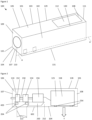
- the housing 105 has a front end 107 for mounting to a tower (not shown) of the wind turbine (not shown), and an opposite rear end 108.
- a front end wall 109 preferably flat, is illustrated as being vertical but may be upwardly inclined and has a front hole 110 for securing the rotor (not shown) of the wind turbine.
- a rear end wall 111 closes the rear end 108. In the illustrated embodiment the rear end wall 111 is vertical, but may have any other desired shape and configuration.
- Each of the roof 101, the opposite sidewalls 102, 103 and the floor 104 comprise a fibre-reinforced polymer composite material.
- each of the front end wall 109 and the rear end wall 111 also comprise a fibre-reinforced polymer composite material.
- the composite nacelle cover 100 may have a panel structure as disclosed in the Applicant's WO-A-2019/034214 in which each wall element comprises an assembly of plural sandwich panels comprising opposite skins of fibre-reinforced polymer composite material laminated to a foam core.
- each sidewall 102, 103 is mounted on a respective metal foundation plate 203 of the bed plate frame 420 by each respective fitting assembly 204.
- the fitting assembly 204 comprises a pair of outer and inner washer plates 205, 206 of metal which sandwich the bracket region 178 of the sidewall 102, 103 therebetween.
- the foundation plate 203 is disposed adjacent to the inner washer plate 206.
- a plurality of threaded bolt and nut fittings 207 bolt together the outer washer plate 205, a reinforced bracket region 178 of the sidewall 102, 103, the inner washer plate 206 and the foundation plate 203.
- the outer and inner washer plates are each adhered to the respective outer and inner surfaces 207, 208 of the bracket region 178 by a respective adhesive layer (not shown).
- the outer and inner washer plates 205, 206 are each comprised of steel having a thickness of from 3 to 50 mm.
- Figure 2 shows schematically the mainshaft 150, mainshaft bearing 152, gearbox 154, generator 156 and transformer 158, although other components, i.e. the yaw system are provided.
- the machinery component that is typically located the furthest rearmost distance from the front end 107 of the nacelle housing 105 e.g. the transformer 158
- the machinery component(s) 125 mounted on the sidewalls 102,103 have a total mass of up to 10 tonnes. Such a mass exerts a high turning moment from the combined mass of the housing 105 and the machinery component(s) 125 on the fixing of the housing 105 to the bed plate frame 420.
- the mass and turning moment load of the machinery component(s) 125 are supported by the sidewalls 102, 103.
- one or more of these machinery component(s) may be indirectly mounted on the sidewalls 102, 103 by being mounted on the roof 101.
- a crane (not shown) may be mounted on the roof 101.
- the housing 105 comprises a structural tube 128 which functions as a vertically displaceable cantilever beam carrying the load, indicated by arrow Y, of the at least one machinery component 125 mounted thereon.
- the at least one machinery component 125 is directly or indirectly mounted on the sidewalls 102, 103 of the housing 105 and the sidewalls 102,103 of the housing 105 directly or indirectly support the load of the at least one machinery component 125.
- the weight of the machinery component(s) 124 of the drive train mounted on the bed plate frame 420 and the main frame 250 is carried by, and transferred to the tower 122 by, the bed plate frame 420.
- the roof 101, opposite sidewalls 102, 103 and floor 104 are assembled at each longitudinally-extending corner 129, 130, 131, 132 of the housing 105 by at least one respective fixing mechanism (not shown) to form a structural joint at least partially along the respective longitudinally-extending corner 129, 130, 131, 132.
- the opposite sidewalls 102, 103 comprise opposite load-bearing webs of the vertically displaceable cantilever beam to carry the turning moment load, of the housing 105 and the at least one machinery component 125 mounted on the housing 105, the turning moment being about the mounting to the bed plate frame 420.
- at least one or both of the roof 101 and floor 104 comprise a respective flange interconnecting the opposite load-bearing webs of the vertically displaceable cantilever beam.
- the vertically displaceable cantilever beam functions to support the vertical turning moment load in a manner similar to an I-beam, or a square hollow profile, with the opposite sidewalls 102, 103 functioning as opposite load-bearing webs and the roof 101 and/or the floor 104 functioning as flanges.
- the structural tube 128 is thereby configured to resist a vertical load of at least 500kN, and a vertical bending moment of at least 3500kNm, applied to the housing 105 at a position laterally of the mounting between the front end 107 of the housing 105 and the bed plate frame 420 which is affixed to the tower 122.
- any of the roof 101, sidewalls 102, 103 and floor 104 may be provided with large openings covered by removable panels which can be temporarily opened to access the interior space 106.
- the opposite wall element may be reinforced to enable that reinforced element to function as the flange of the respective cantilever beam.
- the floor 104 may be reinforced to function as the flange for the vertically displaceable cantilever beam and/or the upper edges of the sidewalls 102, 103 may be reinforced to provide a respective top flange structure for each sidewall 102, 103.
- the hatches may enhance the strength and stiffness of the housing 105; in particular, the closed hatches may provide an increased snow load capability of the roof 101 of the housing 105.
- the roof 101 and floor 104 comprise opposite load-bearing webs of a horizontally displaceable cantilever beam to carry a lateral load, for example a wind load and/or a yawing load applied to the housing 105 about the mounting to the bed plate frame 420.
- the horizontally displaceable cantilever beam functions to support the horizontal turning moment resulting from an applied lateral wind load in a manner similar to an I-beam, or a square hollow profile, with the roof 101 and floor 104 functioning as opposite load-bearing webs and the opposite sidewalls 102, 103 functioning as flanges interconnecting the opposite load-bearing webs of the horizontally displaceable cantilever beam.
- the structural joint along each longitudinally-extending corner 129, 130, 131, 132 has a shear strength of more than 120 kN/m.
- the sidewalls 102, 103, and optionally each of the roof 101 and the floor 104 have an in-plane shear strength of from 25 to 40 N/mm 2 and an in-plane compression strength of from 200 to 250 N/mm 2 .
- the sidewalls 102, 103, and optionally each of the roof 101 and the floor 104 have a shear load strength of greater than 5 kN and a bending moment strength of greater than 6 kNm.
- the housing 105 is structured to act as a vertical cantilever beam which carries the load of the machinery component(s) 125.
- This load can be sufficient to cause elastic deformation of the rear end 108 of the housing 105 in a downward direction.
- snow can accumulate on the roof 101 to provide a significant additional snow load on the housing 105 which can cause elastic deformation of the rear end 108 of the housing 105 in a downward direction.
- the housing 105 needs to be able to flex downwardly relative to the bed plate frame 420 and the main frame 250 in order to be able to carry the load of the machinery component(s) 125 and any additional snow load.
- the housing 105 is exposed to winds, which can apply a significant lateral (i.e. horizontal) load on the housing.
- the housing 105 is structured to act as a horizontal cantilever beam which carries the lateral wind load. This lateral load can be sufficient to cause elastic deformation of the rear end 108 of the housing 105 in a lateral (i.e. transverse) direction.
- the housing 105 needs to be able to flex laterally relative to the bed plate frame 420 and the main frame 250 in order to be able to carry the lateral wind load.
- Such lateral flexing can cause damage of the sidewalls if the sidewalls impact the main frame or the machinery components.
- Such flexing could be prevented entirely by strengthening the composite material walls, but this would significantly increase the weight and dimensions of the nacelle cover.
- Such flexing could also be accommodated by enlarging the width of the nacelle housing, but this would make the nacelle housing too bulky to transport and install.
- the present inventor has accordingly devised a nacelle housing structure which can permit and accommodate lateral flexing of a composite material nacelle cover housing without increasing the weight or volume of the nacelle cover, or its material, assembly and installation costs, and without causing damage to the sidewalls of the housing as a result of impact or wear against an internal framework for supporting machinery within the nacelle cover.
- the nacelle housing structure can permit and accommodate vertical flexing of the composite material nacelle cover housing, for example as a result of a snow load, without increasing the weight or volume of the nacelle cover, or its material, assembly and installation costs.
- the nacelle cover 100 accordingly comprises a brace device 600 affixed between the main frame 250 and a part 602 of the housing 105 for reinforcing the part 602 of the housing 105 against lateral displacement of the housing 105 relative to the main frame 250.
- the brace device 600 is affixed between the main frame 250 and a lower part 602 of the housing 105 for reinforcing the lower part 602 of the housing 105 against lateral displacement of the housing 105 relative to the main frame 250.
- the brace device 600 may be affixed between the main frame 250 and the floor 104.
- the brace device 600 is affixed between the main frame 250 and an upper part of the housing 105 for reinforcing the upper part 602 of the housing 105 against lateral displacement of the housing 105 relative to the main frame 250.
- the brace device 600 may be affixed between the main frame 250 and the roof 101.
- the brace device 600 is positioned laterally spaced from the at least one fitting assembly 204 in the longitudinal direction towards the rear end 108.
- the brace device 600 is affixed between the main frame 250 and the floor 104 of the housing 105, the floor comprising part of the lower part 602 of the housing 105.
- the brace device 600 may be affixed between the main frame 250 and lower edges of the sidewalls 102, 103 of the housing 105.
- the brace device 600 is flexible in a vertical direction and is elastically deformed when the housing 105 is vertically displaced by vertical movement of the rear end 108 relative to the front end 107.
- the brace device 600 prevents or minimises lateral movement of the housing 105 but nevertheless does not significantly restrict vertical movement of the housing 105. This means that the volume, mass and cost of the housing 105 can be minimised for any given combination of machinery components 124, 125 to be located within the nacelle cover 100, while nevertheless accommodating high vertical and horizontal loads which may be applied to the nacelle cover 100 during a service life of many years.
- the brace device 600 By providing the brace device 600, the lateral or sideways movement of the housing 105 is restricted, which prevents the sidewalls 102, 103 impacting against the main frame 250, which would otherwise damage the composite material of the sidewalls 102, 103. Nevertheless, the brace device 600 is flexible in a vertical direction and so permits vertical movement of the housing 105, for example when a snow load is on the roof 101 of the housing 105.
- the housing 105 would have to be increased in width or reinforced, or the steel framework would need to be larger and heavier, to prevent the sidewalls 102, 103 impacting against the main frame 250, but these modifications would increase one or more of the volume, mass and cost of the housing 105.
- the provision of the brace device 600 achieves a low cost, low weight and low volume solution for the housing which enables the housing 105 to function as a structural tube 128 without inadvertent damage to the sidewalls 102, 103 during service caused by lateral wind loads.
- the brace device 600 comprises an elongate spar 604 which has opposite ends 606, 608 which are affixed to respective opposite sides 610, 612 of the main frame 250 by fittings such as bolt fittings 616, and a central part 614 which is affixed to the floor 104 of the housing 105 by fittings such as bolt fittings 618.
- the elongate spar 604 comprises a fibre-reinforced polymer composite material; however it may be made of a polymer or metal, either as a metal bar, strip or wire, or other composite material.
- the elongate spar 604 comprises a flexible sheet 605 which has high tensile strength, and thereby high stiffness, in a direction parallel to the plane of the sheet 605, and a high flexibility, and thereby low stiffness, in a direction orthogonal to the plane of the sheet 605.
- First and second intermediate parts 620a, 620b of the elongate spar 604 are located between the central part 614 and a respective one of the opposite ends 606, 608.
- Each intermediate part 620a, 620b is flexible in a vertical direction and is elastically deformed when the housing 105 is vertically displaced by vertical movement of the rear end 108 relative to the front end 107.
- the brace device 600 comprises a pair of the elongate spars 604a, 604b which are spaced from each other in the longitudinal direction, as shown in Figure 3 .
- a shock absorber 650 is provided on an outer longitudinally- extending side 652 of each of the beams 640, 642.
- the shock absorber 650 is positioned inwardly of the housing 105 and spaced from an inner side surface 664 of the housing 105.
- the shock absorber 650 extends longitudinally and is shaped and dimensioned to fit to the respective beam 640, 642 so that the shock absorber 650 can protect the sidewall 102, 103 from impacting the respective beam 640, 642.
- each beam 640, 642 is shaped as an I-beam and the shock absorber 650 has a U-shaped cross-section to fit to an edge of the upper web 668 of the I-beam.
- the beams 640, 642 may have any other suitable structure to function as a main frame to support the desired machinery components and the shock absorber 650 may be correspondingly shaped and dimensioned to fit to the respective beam 640, 642.
- the shock absorber 650 comprises a body 656 of an elastomeric material which extends longitudinally along at least a part of the length of the respective beam 640, 642.
- the side surface 664 of each sidewall 102, 103 is covered by a metal plate 666 which can contact the shock absorber 650 prevent wear of the sidewall 102, 103.
- the shock absorber 650 can function to avoid or minimise wear and deformation of the sidewalls 102, 103 in the event of lateral movement of the housing 105 relative to the main frame 250, in the event that the housing 105 is deflected laterally despite the presence of the brace device 600.
- the shock absorber 650 is preferably provided if the main frame 250, or machinery component(s) mounted on the main frame 250, are likely during service to be touched by the sidewalls 102, 103 when the sidewalls 102, 103 deform laterally.
- the deflection distance of the sidewalls 102, 103 increases for any given angle of lateral deflection. Consequently, for longer main frames 250, there is an increased likelihood that a shock absorber 650 would be installed on the outer lateral sides of the main frame 250 to minimise or prevent wear or deformation of the sidewalls 102, 103 by the main frame 250.
Landscapes
- Engineering & Computer Science (AREA)
- Life Sciences & Earth Sciences (AREA)
- Sustainable Development (AREA)
- Sustainable Energy (AREA)
- Chemical & Material Sciences (AREA)
- Combustion & Propulsion (AREA)
- Mechanical Engineering (AREA)
- General Engineering & Computer Science (AREA)
- Wind Motors (AREA)
Claims (15)
- Nacelle destinée à une éolienne, dans laquelle la nacelle (100) comprend une enveloppe de nacelle formée d'un habitacle allongé (105) qui définit un espace intérieur contenant des composants de machinerie de l'éolienne, l'habitacle (105) comportant une extrémité avant (107) montée sur un mât (122) de l'éolienne, et une extrémité arrière opposée (108), dans laquelle l'habitacle allongé (105) comprend un matériau composite polymère renforcé de fibres,
caractérisée en ce que l'extrémité avant (107) de l'habitacle (105) est montée sur un cadre de plaque de base (420) qui est fixé au mât (122), l'extrémité avant (107) s'ajuste au cadre de plaque de base (420) par le biais d'au moins un ensemble raccord (204), un cadre principal (250) est fixé au cadre de plaque de base (420) et s'étend dans une direction longitudinale le long de l'habitacle (105) vers l'extrémité arrière (108), le cadre principal (250) supporte au moins une partie d'un train d'entraînement (124) de l'éolienne, l'habitacle (105) supporte au moins un composant de machinerie (125) de l'éolienne qui est monté sur l'habitacle (105) au niveau de l'extrémité arrière (108), l'habitacle (105) comprend un tube structurel (128) qui fonctionne comme une poutre en porte-à-faux déplaçable verticalement qui porte la charge dudit au moins un composant de machinerie (125) monté dessus, et la nacelle (100) comprend en outre un dispositif de renfort (600) qui est fixé entre le cadre principal (250) et une partie (602) de l'habitacle (105) afin que la partie (602) de l'habitacle (105) se renforce contre un déplacement latéral de l'habitacle (105) par rapport au cadre principal (250). - Nacelle selon la revendication 1, dans laquelle le dispositif de renfort (600) est positionné latéralement à distance dudit au moins un ensemble raccord (204) dans la direction longitudinale vers l'extrémité arrière (108).
- Nacelle selon la revendication 1 ou 2, dans laquelle le dispositif de renfort (600) est flexible dans une direction verticale et est déformé élastiquement lorsque l'habitacle (105) est déplacé verticalement par le biais d'un mouvement vertical de l'extrémité arrière (108) par rapport à l'extrémité avant (107).
- Nacelle selon l'une quelconque des revendications 1 à 3, dans laquelle le dispositif de renfort (600) est fixé entre le cadre principal (250) et une partie inférieure (602) de l'habitacle (105) afin que la partie inférieure (602) de l'habitacle (105) se renforce contre un déplacement latéral de l'habitacle (105) par rapport au cadre principal (250), et éventuellement dans laquelle le dispositif de renfort (600) est fixé entre le cadre principal (250) et un plancher (104) de l'habitacle (105).
- Nacelle selon l'une quelconque des revendications précédentes, dans laquelle le dispositif de renfort (600) comprend un longeron allongé (604) qui comprend des extrémités opposées (606, 608) qui sont fixées aux côtés opposés respectifs (610, 612) du cadre principal (250), et une partie centrale (614) qui est fixée au plancher (104) ou au toit (101) de l'habitacle (105).
- Nacelle selon la revendication 5, dans laquelle le longeron allongé (604) comprend une feuille flexible (605) qui a une résistance à la traction élevée, et ainsi une rigidité élevée, dans une direction parallèle au plan de la feuille (605), et une flexibilité élevée, et ainsi une faible rigidité, dans une direction orthogonale au plan de la feuille (605).
- Nacelle selon la revendication 5 ou 6, dans laquelle des première et deuxième parties intermédiaires (620a, 620b) du longeron allongé (604) sont situées entre la partie centrale (614) et l'une respective des extrémités opposées (606, 608), et chaque partie intermédiaire (620a, 620b) est flexible dans une direction verticale et se déforme élastiquement lorsque l'habitacle (105) est déplacé verticalement par le biais d'un mouvement vertical de l'extrémité arrière (108) par rapport à l'extrémité avant (107).
- Nacelle selon l'une quelconque des revendications 5 à 7, dans laquelle le longeron allongé (604) comprend un matériau composite polymère renforcé de fibres.
- Nacelle selon l'une quelconque des revendications 5 à 8, dans laquelle le dispositif de renfort (600) comprend une paire desdits longerons allongés (604a, 604b) qui sont espacés l'un de l'autre dans la direction longitudinale.
- Nacelle selon l'une quelconque des revendications 1 à 9, dans laquelle le cadre principal (250) comprend une paire de poutres (640, 642) qui s'étendent depuis le cadre de plaque de base (420) dans la direction longitudinale et sont espacées l'une de l'autre dans une direction transversale orthogonale à la direction longitudinale, et chaque poutre (640, 642) comprend une extrémité libre (644) qui est située plus près de l'extrémité avant (107) de l'habitacle (105) que ledit au moins un composant de machinerie (125) de l'éolienne.
- Nacelle selon la revendication 10, dans laquelle un amortisseur de chocs (650) est prévu sur un côté externe s'étendant longitudinalement (652) de chacune des poutres (640, 642), l'amortisseur de chocs (650) étant positionné vers l'intérieur de l'habitacle (105) et espacé d'une surface latérale interne (664) de l'habitacle (105) de telle sorte que, lorsque l'habitacle (105) est déformé latéralement d'une distance supérieure à une distance prédéterminée, la surface latérale (664) entre en prise avec l'amortisseur de chocs (650).
- Nacelle selon la revendication 11, dans laquelle l'amortisseur de chocs (650) comprend un corps d'un matériau élastomère qui s'étend longitudinalement le long d'au moins une partie de la longueur de la poutre respective (640, 642).
- Nacelle selon l'une quelconque des revendications 1 à 12, dans laquelle la nacelle (100) comprend un toit (101), des parois latérales opposées (102, 103) et un plancher (104) assemblés entre eux afin de former l'habitacle allongé (105), dans laquelle chacun parmi le toit (101), les parois latérales opposées (102, 103) et le plancher (104) comprend un matériau composite polymère renforcé de fibres, dans laquelle ledit au moins l'un dudit composant de machinerie (125) est monté sur au moins un support (254) comprenant une zone renforcée du plancher (104) qui s'ajuste aux parois latérales (102, 103), un plancher transversal intérieur renforcé qui s'ajuste aux parois latérales (102, 103) ou un ensemble support transversal qui s'ajuste aux parois latérales (102, 103), et ainsi ledit composant de machinerie (125) est monté indirectement sur les parois latérales (102, 103) de l'habitacle (105) et les parois latérales (102, 103) de l'habitacle (105) supportent indirectement la charge dudit composant de machinerie (125).
- Nacelle selon la revendication 13, dans laquelle ledit au moins un composant de machinerie (125) comprend un transformateur (158) de l'éolienne qui est monté directement ou indirectement sur les parois latérales (102, 103) de l'habitacle (105) à un emplacement le long de l'habitacle (105) qui est espacé latéralement du cadre principal (250), et les parois latérales (102, 103) de l'habitacle (105) supportent directement ou indirectement la charge du transformateur (158).
- Nacelle selon la revendication 13 ou 14, dans laquelle le toit (101), les parois latérales opposées (102, 103) et le plancher (104) sont assemblés moyennant quoi les parois latérales opposées (102, 103) comprennent des âmes porteuses opposées de la poutre en porte-à-faux déplaçable verticalement afin de porter une charge de moment de rotation vertical, le moment de rotation étant autour du montage sur le cadre de plaque de base (420), de l'habitacle (105) et dudit au moins un composant de machinerie (125) monté sur l'habitacle, et au moins l'un ou les deux parmi le toit (101) et le plancher (104) comprennent une semelle respective qui relie les âmes porteuses opposées de la poutre en porte-à-faux déplaçable verticalement, et le toit (101) et le plancher (104) comprennent des âmes porteuses opposées d'une poutre en porte-à-faux déplaçable horizontalement afin de porter une charge latérale appliquée à l'habitacle (105) autour du montage sur le cadre de plaque de base (420), et au moins l'un ou les deux parmi les parois latérales opposées (102, 103) comprennent une semelle respective reliant les âmes porteuses opposées de la poutre en porte-à-faux déplaçable horizontalement.
Applications Claiming Priority (6)
| Application Number | Priority Date | Filing Date | Title |
|---|---|---|---|
| DKPA201970699A DK201970699A1 (en) | 2019-11-15 | 2019-11-15 | Utilization of a composite nacelle cover as the load-carrying Structure for main machinery components. |
| DKPA202070253A DK180512B1 (en) | 2019-11-15 | 2020-04-24 | Nacelle cover for a wind turbine |
| DKPA202070252A DK180482B1 (en) | 2019-11-15 | 2020-04-24 | Nacelle cover for a wind turbine |
| DKPA202070254A DK180515B1 (en) | 2019-11-15 | 2020-04-24 | Nacelle cover for a wind turbine |
| DKPA202070588A DK180514B1 (en) | 2019-11-15 | 2020-09-11 | Nacelle for a wind turbine |
| PCT/EP2020/082114 WO2021094571A1 (fr) | 2019-11-15 | 2020-11-13 | Nacelle destinée à une éolienne |
Publications (2)
| Publication Number | Publication Date |
|---|---|
| EP4045797A1 EP4045797A1 (fr) | 2022-08-24 |
| EP4045797B1 true EP4045797B1 (fr) | 2024-07-10 |
Family
ID=73449075
Family Applications (1)
| Application Number | Title | Priority Date | Filing Date |
|---|---|---|---|
| EP20807369.2A Active EP4045797B1 (fr) | 2019-11-15 | 2020-11-13 | Nacelle destinée à une éolienne |
Country Status (2)
| Country | Link |
|---|---|
| EP (1) | EP4045797B1 (fr) |
| WO (1) | WO2021094571A1 (fr) |
Families Citing this family (1)
| Publication number | Priority date | Publication date | Assignee | Title |
|---|---|---|---|---|
| TW202248528A (zh) | 2021-05-26 | 2022-12-16 | 丹麥商維斯塔斯風力系統有限公司 | 含有具偏移重心之機艙之風力機 |
Citations (1)
| Publication number | Priority date | Publication date | Assignee | Title |
|---|---|---|---|---|
| EP3247899B1 (fr) * | 2015-01-22 | 2018-10-17 | Vestas Wind Systems A/S | Nacelle d'éolienne |
Family Cites Families (5)
| Publication number | Priority date | Publication date | Assignee | Title |
|---|---|---|---|---|
| EP1336755A1 (fr) | 2002-02-19 | 2003-08-20 | Vestas Wind Systems A/S | Méthode pour le transport d'une nacelle d'éolienne |
| US7075192B2 (en) * | 2004-04-19 | 2006-07-11 | Northern Power Systems, Inc. | Direct drive wind turbine |
| US8591186B2 (en) | 2009-11-17 | 2013-11-26 | Vestas Wind Systems A/S | Nacelle for wind turbine |
| JP6351659B2 (ja) | 2016-05-20 | 2018-07-04 | 三菱重工業株式会社 | 風車用ナセル及び風力発電装置並びに風力発電装置の部品昇降方法 |
| DK179720B1 (en) | 2017-08-16 | 2019-04-11 | Jupiter Bach A/S | A method of manufacturing composite laminate panel sub-elements for a modular assembly structure, a method of assembling the sub-elements, and a structure assembled of the panel sub-elements |
-
2020
- 2020-11-13 EP EP20807369.2A patent/EP4045797B1/fr active Active
- 2020-11-13 WO PCT/EP2020/082114 patent/WO2021094571A1/fr not_active Ceased
Patent Citations (1)
| Publication number | Priority date | Publication date | Assignee | Title |
|---|---|---|---|---|
| EP3247899B1 (fr) * | 2015-01-22 | 2018-10-17 | Vestas Wind Systems A/S | Nacelle d'éolienne |
Also Published As
| Publication number | Publication date |
|---|---|
| WO2021094571A1 (fr) | 2021-05-20 |
| EP4045797A1 (fr) | 2022-08-24 |
Similar Documents
| Publication | Publication Date | Title |
|---|---|---|
| US12123404B2 (en) | Nacelle cover for a wind turbine | |
| CN110219778B (zh) | 罩盖结构和风力涡轮机 | |
| EP3568593B1 (fr) | Trappes de nacelle et plateforme d'hélitreuillage | |
| US20240052813A1 (en) | Utilization of a Composite Nacelle Cover as the Load-Carrying Structure for Main Machinery Components for a Wind Turbine | |
| EP4204684B1 (fr) | Nacelle destinée à une éolienne | |
| EP4045797B1 (fr) | Nacelle destinée à une éolienne | |
| DK180514B1 (en) | Nacelle for a wind turbine | |
| EP3504427B1 (fr) | Structure de nacelle autoportante pour éoliennes | |
| EP4045796B1 (fr) | Nacelle destinée à une éolienne |
Legal Events
| Date | Code | Title | Description |
|---|---|---|---|
| STAA | Information on the status of an ep patent application or granted ep patent |
Free format text: STATUS: UNKNOWN |
|
| STAA | Information on the status of an ep patent application or granted ep patent |
Free format text: STATUS: THE INTERNATIONAL PUBLICATION HAS BEEN MADE |
|
| PUAI | Public reference made under article 153(3) epc to a published international application that has entered the european phase |
Free format text: ORIGINAL CODE: 0009012 |
|
| STAA | Information on the status of an ep patent application or granted ep patent |
Free format text: STATUS: REQUEST FOR EXAMINATION WAS MADE |
|
| 17P | Request for examination filed |
Effective date: 20220518 |
|
| AK | Designated contracting states |
Kind code of ref document: A1 Designated state(s): AL AT BE BG CH CY CZ DE DK EE ES FI FR GB GR HR HU IE IS IT LI LT LU LV MC MK MT NL NO PL PT RO RS SE SI SK SM TR |
|
| DAV | Request for validation of the european patent (deleted) | ||
| DAX | Request for extension of the european patent (deleted) | ||
| GRAP | Despatch of communication of intention to grant a patent |
Free format text: ORIGINAL CODE: EPIDOSNIGR1 |
|
| STAA | Information on the status of an ep patent application or granted ep patent |
Free format text: STATUS: GRANT OF PATENT IS INTENDED |
|
| INTG | Intention to grant announced |
Effective date: 20240208 |
|
| GRAS | Grant fee paid |
Free format text: ORIGINAL CODE: EPIDOSNIGR3 |
|
| GRAA | (expected) grant |
Free format text: ORIGINAL CODE: 0009210 |
|
| STAA | Information on the status of an ep patent application or granted ep patent |
Free format text: STATUS: THE PATENT HAS BEEN GRANTED |
|
| AK | Designated contracting states |
Kind code of ref document: B1 Designated state(s): AL AT BE BG CH CY CZ DE DK EE ES FI FR GB GR HR HU IE IS IT LI LT LU LV MC MK MT NL NO PL PT RO RS SE SI SK SM TR |
|
| REG | Reference to a national code |
Ref country code: CH Ref legal event code: EP |
|
| REG | Reference to a national code |
Ref country code: DE Ref legal event code: R096 Ref document number: 602020033843 Country of ref document: DE |
|
| REG | Reference to a national code |
Ref country code: LT Ref legal event code: MG9D |
|
| REG | Reference to a national code |
Ref country code: NL Ref legal event code: MP Effective date: 20240710 |
|
| PG25 | Lapsed in a contracting state [announced via postgrant information from national office to epo] |
Ref country code: PT Free format text: LAPSE BECAUSE OF FAILURE TO SUBMIT A TRANSLATION OF THE DESCRIPTION OR TO PAY THE FEE WITHIN THE PRESCRIBED TIME-LIMIT Effective date: 20241111 |
|
| REG | Reference to a national code |
Ref country code: AT Ref legal event code: MK05 Ref document number: 1702235 Country of ref document: AT Kind code of ref document: T Effective date: 20240710 |
|
| PG25 | Lapsed in a contracting state [announced via postgrant information from national office to epo] |
Ref country code: NL Free format text: LAPSE BECAUSE OF FAILURE TO SUBMIT A TRANSLATION OF THE DESCRIPTION OR TO PAY THE FEE WITHIN THE PRESCRIBED TIME-LIMIT Effective date: 20240710 |
|
| PG25 | Lapsed in a contracting state [announced via postgrant information from national office to epo] |
Ref country code: PT Free format text: LAPSE BECAUSE OF FAILURE TO SUBMIT A TRANSLATION OF THE DESCRIPTION OR TO PAY THE FEE WITHIN THE PRESCRIBED TIME-LIMIT Effective date: 20241111 Ref country code: NL Free format text: LAPSE BECAUSE OF FAILURE TO SUBMIT A TRANSLATION OF THE DESCRIPTION OR TO PAY THE FEE WITHIN THE PRESCRIBED TIME-LIMIT Effective date: 20240710 |
|
| PG25 | Lapsed in a contracting state [announced via postgrant information from national office to epo] |
Ref country code: NO Free format text: LAPSE BECAUSE OF FAILURE TO SUBMIT A TRANSLATION OF THE DESCRIPTION OR TO PAY THE FEE WITHIN THE PRESCRIBED TIME-LIMIT Effective date: 20241010 |
|
| PG25 | Lapsed in a contracting state [announced via postgrant information from national office to epo] |
Ref country code: GR Free format text: LAPSE BECAUSE OF FAILURE TO SUBMIT A TRANSLATION OF THE DESCRIPTION OR TO PAY THE FEE WITHIN THE PRESCRIBED TIME-LIMIT Effective date: 20241011 Ref country code: FI Free format text: LAPSE BECAUSE OF FAILURE TO SUBMIT A TRANSLATION OF THE DESCRIPTION OR TO PAY THE FEE WITHIN THE PRESCRIBED TIME-LIMIT Effective date: 20240710 Ref country code: PL Free format text: LAPSE BECAUSE OF FAILURE TO SUBMIT A TRANSLATION OF THE DESCRIPTION OR TO PAY THE FEE WITHIN THE PRESCRIBED TIME-LIMIT Effective date: 20240710 |
|
| PG25 | Lapsed in a contracting state [announced via postgrant information from national office to epo] |
Ref country code: BG Free format text: LAPSE BECAUSE OF FAILURE TO SUBMIT A TRANSLATION OF THE DESCRIPTION OR TO PAY THE FEE WITHIN THE PRESCRIBED TIME-LIMIT Effective date: 20240710 |
|
| PG25 | Lapsed in a contracting state [announced via postgrant information from national office to epo] |
Ref country code: LV Free format text: LAPSE BECAUSE OF FAILURE TO SUBMIT A TRANSLATION OF THE DESCRIPTION OR TO PAY THE FEE WITHIN THE PRESCRIBED TIME-LIMIT Effective date: 20240710 |
|
| PG25 | Lapsed in a contracting state [announced via postgrant information from national office to epo] |
Ref country code: AT Free format text: LAPSE BECAUSE OF FAILURE TO SUBMIT A TRANSLATION OF THE DESCRIPTION OR TO PAY THE FEE WITHIN THE PRESCRIBED TIME-LIMIT Effective date: 20240710 Ref country code: IS Free format text: LAPSE BECAUSE OF FAILURE TO SUBMIT A TRANSLATION OF THE DESCRIPTION OR TO PAY THE FEE WITHIN THE PRESCRIBED TIME-LIMIT Effective date: 20241110 |
|
| PG25 | Lapsed in a contracting state [announced via postgrant information from national office to epo] |
Ref country code: HR Free format text: LAPSE BECAUSE OF FAILURE TO SUBMIT A TRANSLATION OF THE DESCRIPTION OR TO PAY THE FEE WITHIN THE PRESCRIBED TIME-LIMIT Effective date: 20240710 |
|
| PG25 | Lapsed in a contracting state [announced via postgrant information from national office to epo] |
Ref country code: ES Free format text: LAPSE BECAUSE OF FAILURE TO SUBMIT A TRANSLATION OF THE DESCRIPTION OR TO PAY THE FEE WITHIN THE PRESCRIBED TIME-LIMIT Effective date: 20240710 Ref country code: RS Free format text: LAPSE BECAUSE OF FAILURE TO SUBMIT A TRANSLATION OF THE DESCRIPTION OR TO PAY THE FEE WITHIN THE PRESCRIBED TIME-LIMIT Effective date: 20241010 |
|
| PG25 | Lapsed in a contracting state [announced via postgrant information from national office to epo] |
Ref country code: RS Free format text: LAPSE BECAUSE OF FAILURE TO SUBMIT A TRANSLATION OF THE DESCRIPTION OR TO PAY THE FEE WITHIN THE PRESCRIBED TIME-LIMIT Effective date: 20241010 Ref country code: PL Free format text: LAPSE BECAUSE OF FAILURE TO SUBMIT A TRANSLATION OF THE DESCRIPTION OR TO PAY THE FEE WITHIN THE PRESCRIBED TIME-LIMIT Effective date: 20240710 Ref country code: NO Free format text: LAPSE BECAUSE OF FAILURE TO SUBMIT A TRANSLATION OF THE DESCRIPTION OR TO PAY THE FEE WITHIN THE PRESCRIBED TIME-LIMIT Effective date: 20241010 Ref country code: LV Free format text: LAPSE BECAUSE OF FAILURE TO SUBMIT A TRANSLATION OF THE DESCRIPTION OR TO PAY THE FEE WITHIN THE PRESCRIBED TIME-LIMIT Effective date: 20240710 Ref country code: IS Free format text: LAPSE BECAUSE OF FAILURE TO SUBMIT A TRANSLATION OF THE DESCRIPTION OR TO PAY THE FEE WITHIN THE PRESCRIBED TIME-LIMIT Effective date: 20241110 Ref country code: HR Free format text: LAPSE BECAUSE OF FAILURE TO SUBMIT A TRANSLATION OF THE DESCRIPTION OR TO PAY THE FEE WITHIN THE PRESCRIBED TIME-LIMIT Effective date: 20240710 Ref country code: GR Free format text: LAPSE BECAUSE OF FAILURE TO SUBMIT A TRANSLATION OF THE DESCRIPTION OR TO PAY THE FEE WITHIN THE PRESCRIBED TIME-LIMIT Effective date: 20241011 Ref country code: FI Free format text: LAPSE BECAUSE OF FAILURE TO SUBMIT A TRANSLATION OF THE DESCRIPTION OR TO PAY THE FEE WITHIN THE PRESCRIBED TIME-LIMIT Effective date: 20240710 Ref country code: ES Free format text: LAPSE BECAUSE OF FAILURE TO SUBMIT A TRANSLATION OF THE DESCRIPTION OR TO PAY THE FEE WITHIN THE PRESCRIBED TIME-LIMIT Effective date: 20240710 Ref country code: BG Free format text: LAPSE BECAUSE OF FAILURE TO SUBMIT A TRANSLATION OF THE DESCRIPTION OR TO PAY THE FEE WITHIN THE PRESCRIBED TIME-LIMIT Effective date: 20240710 Ref country code: AT Free format text: LAPSE BECAUSE OF FAILURE TO SUBMIT A TRANSLATION OF THE DESCRIPTION OR TO PAY THE FEE WITHIN THE PRESCRIBED TIME-LIMIT Effective date: 20240710 |
|
| REG | Reference to a national code |
Ref country code: DE Ref legal event code: R097 Ref document number: 602020033843 Country of ref document: DE |
|
| PG25 | Lapsed in a contracting state [announced via postgrant information from national office to epo] |
Ref country code: SM Free format text: LAPSE BECAUSE OF FAILURE TO SUBMIT A TRANSLATION OF THE DESCRIPTION OR TO PAY THE FEE WITHIN THE PRESCRIBED TIME-LIMIT Effective date: 20240710 Ref country code: DK Free format text: LAPSE BECAUSE OF FAILURE TO SUBMIT A TRANSLATION OF THE DESCRIPTION OR TO PAY THE FEE WITHIN THE PRESCRIBED TIME-LIMIT Effective date: 20240710 Ref country code: RO Free format text: LAPSE BECAUSE OF FAILURE TO SUBMIT A TRANSLATION OF THE DESCRIPTION OR TO PAY THE FEE WITHIN THE PRESCRIBED TIME-LIMIT Effective date: 20240710 |
|
| PG25 | Lapsed in a contracting state [announced via postgrant information from national office to epo] |
Ref country code: EE Free format text: LAPSE BECAUSE OF FAILURE TO SUBMIT A TRANSLATION OF THE DESCRIPTION OR TO PAY THE FEE WITHIN THE PRESCRIBED TIME-LIMIT Effective date: 20240710 |
|
| PG25 | Lapsed in a contracting state [announced via postgrant information from national office to epo] |
Ref country code: CZ Free format text: LAPSE BECAUSE OF FAILURE TO SUBMIT A TRANSLATION OF THE DESCRIPTION OR TO PAY THE FEE WITHIN THE PRESCRIBED TIME-LIMIT Effective date: 20240710 |
|
| PG25 | Lapsed in a contracting state [announced via postgrant information from national office to epo] |
Ref country code: IT Free format text: LAPSE BECAUSE OF FAILURE TO SUBMIT A TRANSLATION OF THE DESCRIPTION OR TO PAY THE FEE WITHIN THE PRESCRIBED TIME-LIMIT Effective date: 20240710 Ref country code: SK Free format text: LAPSE BECAUSE OF FAILURE TO SUBMIT A TRANSLATION OF THE DESCRIPTION OR TO PAY THE FEE WITHIN THE PRESCRIBED TIME-LIMIT Effective date: 20240710 |
|
| PLBE | No opposition filed within time limit |
Free format text: ORIGINAL CODE: 0009261 |
|
| STAA | Information on the status of an ep patent application or granted ep patent |
Free format text: STATUS: NO OPPOSITION FILED WITHIN TIME LIMIT |
|
| 26N | No opposition filed |
Effective date: 20250411 |
|
| REG | Reference to a national code |
Ref country code: CH Ref legal event code: PL |
|
| PG25 | Lapsed in a contracting state [announced via postgrant information from national office to epo] |
Ref country code: MC Free format text: LAPSE BECAUSE OF FAILURE TO SUBMIT A TRANSLATION OF THE DESCRIPTION OR TO PAY THE FEE WITHIN THE PRESCRIBED TIME-LIMIT Effective date: 20240710 |
|
| PG25 | Lapsed in a contracting state [announced via postgrant information from national office to epo] |
Ref country code: LU Free format text: LAPSE BECAUSE OF NON-PAYMENT OF DUE FEES Effective date: 20241113 |
|
| REG | Reference to a national code |
Ref country code: CH Ref legal event code: PL |
|
| PG25 | Lapsed in a contracting state [announced via postgrant information from national office to epo] |
Ref country code: CH Free format text: LAPSE BECAUSE OF NON-PAYMENT OF DUE FEES Effective date: 20241130 |
|
| REG | Reference to a national code |
Ref country code: BE Ref legal event code: MM Effective date: 20241130 |
|
| PG25 | Lapsed in a contracting state [announced via postgrant information from national office to epo] |
Ref country code: SE Free format text: LAPSE BECAUSE OF FAILURE TO SUBMIT A TRANSLATION OF THE DESCRIPTION OR TO PAY THE FEE WITHIN THE PRESCRIBED TIME-LIMIT Effective date: 20240710 |
|
| PG25 | Lapsed in a contracting state [announced via postgrant information from national office to epo] |
Ref country code: BE Free format text: LAPSE BECAUSE OF NON-PAYMENT OF DUE FEES Effective date: 20241130 |
|
| PG25 | Lapsed in a contracting state [announced via postgrant information from national office to epo] |
Ref country code: IE Free format text: LAPSE BECAUSE OF NON-PAYMENT OF DUE FEES Effective date: 20241113 |
|
| REG | Reference to a national code |
Ref country code: DE Ref legal event code: R082 Ref document number: 602020033843 Country of ref document: DE Representative=s name: WESTPHAL, MUSSGNUG & PARTNER PATENTANWAELTE MI, DE |
|
| PGFP | Annual fee paid to national office [announced via postgrant information from national office to epo] |
Ref country code: DE Payment date: 20251029 Year of fee payment: 6 |
|
| PGFP | Annual fee paid to national office [announced via postgrant information from national office to epo] |
Ref country code: GB Payment date: 20251014 Year of fee payment: 6 |
|
| PGFP | Annual fee paid to national office [announced via postgrant information from national office to epo] |
Ref country code: FR Payment date: 20251013 Year of fee payment: 6 |
|
| PG25 | Lapsed in a contracting state [announced via postgrant information from national office to epo] |
Ref country code: HU Free format text: LAPSE BECAUSE OF FAILURE TO SUBMIT A TRANSLATION OF THE DESCRIPTION OR TO PAY THE FEE WITHIN THE PRESCRIBED TIME-LIMIT; INVALID AB INITIO Effective date: 20201113 |
|
| PG25 | Lapsed in a contracting state [announced via postgrant information from national office to epo] |
Ref country code: CY Free format text: LAPSE BECAUSE OF FAILURE TO SUBMIT A TRANSLATION OF THE DESCRIPTION OR TO PAY THE FEE WITHIN THE PRESCRIBED TIME-LIMIT; INVALID AB INITIO Effective date: 20201113 |