EP4045823B1 - Wellenanordnung, getriebe mit einer wellenanordnung und extruder mit getriebe mit einer wellenanordnung, mit einer relativ zu einem flanschteil drehbar gelagerten welle - Google Patents
Wellenanordnung, getriebe mit einer wellenanordnung und extruder mit getriebe mit einer wellenanordnung, mit einer relativ zu einem flanschteil drehbar gelagerten welle Download PDFInfo
- Publication number
- EP4045823B1 EP4045823B1 EP20786450.5A EP20786450A EP4045823B1 EP 4045823 B1 EP4045823 B1 EP 4045823B1 EP 20786450 A EP20786450 A EP 20786450A EP 4045823 B1 EP4045823 B1 EP 4045823B1
- Authority
- EP
- European Patent Office
- Prior art keywords
- ring
- sleeve
- shaft
- annular groove
- arrangement according
- Prior art date
- Legal status (The legal status is an assumption and is not a legal conclusion. Google has not performed a legal analysis and makes no representation as to the accuracy of the status listed.)
- Active
Links
Images
Classifications
-
- F—MECHANICAL ENGINEERING; LIGHTING; HEATING; WEAPONS; BLASTING
- F16—ENGINEERING ELEMENTS AND UNITS; GENERAL MEASURES FOR PRODUCING AND MAINTAINING EFFECTIVE FUNCTIONING OF MACHINES OR INSTALLATIONS; THERMAL INSULATION IN GENERAL
- F16C—SHAFTS; FLEXIBLE SHAFTS; ELEMENTS OR CRANKSHAFT MECHANISMS; ROTARY BODIES OTHER THAN GEARING ELEMENTS; BEARINGS
- F16C17/00—Sliding-contact bearings for exclusively rotary movement
- F16C17/02—Sliding-contact bearings for exclusively rotary movement for radial load only
-
- F—MECHANICAL ENGINEERING; LIGHTING; HEATING; WEAPONS; BLASTING
- F16—ENGINEERING ELEMENTS AND UNITS; GENERAL MEASURES FOR PRODUCING AND MAINTAINING EFFECTIVE FUNCTIONING OF MACHINES OR INSTALLATIONS; THERMAL INSULATION IN GENERAL
- F16C—SHAFTS; FLEXIBLE SHAFTS; ELEMENTS OR CRANKSHAFT MECHANISMS; ROTARY BODIES OTHER THAN GEARING ELEMENTS; BEARINGS
- F16C33/00—Parts of bearings; Special methods for making bearings or parts thereof
- F16C33/72—Sealings
- F16C33/723—Shaft end sealing means, e.g. cup-shaped caps or covers
-
- F—MECHANICAL ENGINEERING; LIGHTING; HEATING; WEAPONS; BLASTING
- F16—ENGINEERING ELEMENTS AND UNITS; GENERAL MEASURES FOR PRODUCING AND MAINTAINING EFFECTIVE FUNCTIONING OF MACHINES OR INSTALLATIONS; THERMAL INSULATION IN GENERAL
- F16C—SHAFTS; FLEXIBLE SHAFTS; ELEMENTS OR CRANKSHAFT MECHANISMS; ROTARY BODIES OTHER THAN GEARING ELEMENTS; BEARINGS
- F16C33/00—Parts of bearings; Special methods for making bearings or parts thereof
- F16C33/72—Sealings
- F16C33/74—Sealings of sliding-contact bearings
-
- F—MECHANICAL ENGINEERING; LIGHTING; HEATING; WEAPONS; BLASTING
- F16—ENGINEERING ELEMENTS AND UNITS; GENERAL MEASURES FOR PRODUCING AND MAINTAINING EFFECTIVE FUNCTIONING OF MACHINES OR INSTALLATIONS; THERMAL INSULATION IN GENERAL
- F16J—PISTONS; CYLINDERS; SEALINGS
- F16J15/00—Sealings
- F16J15/16—Sealings between relatively-moving surfaces
- F16J15/32—Sealings between relatively-moving surfaces with elastic sealings, e.g. O-rings
- F16J15/3204—Sealings between relatively-moving surfaces with elastic sealings, e.g. O-rings with at least one lip
- F16J15/3208—Sealings between relatively-moving surfaces with elastic sealings, e.g. O-rings with at least one lip provided with tension elements, e.g. elastic rings
-
- F—MECHANICAL ENGINEERING; LIGHTING; HEATING; WEAPONS; BLASTING
- F16—ENGINEERING ELEMENTS AND UNITS; GENERAL MEASURES FOR PRODUCING AND MAINTAINING EFFECTIVE FUNCTIONING OF MACHINES OR INSTALLATIONS; THERMAL INSULATION IN GENERAL
- F16J—PISTONS; CYLINDERS; SEALINGS
- F16J15/00—Sealings
- F16J15/16—Sealings between relatively-moving surfaces
- F16J15/32—Sealings between relatively-moving surfaces with elastic sealings, e.g. O-rings
- F16J15/3204—Sealings between relatively-moving surfaces with elastic sealings, e.g. O-rings with at least one lip
- F16J15/3232—Sealings between relatively-moving surfaces with elastic sealings, e.g. O-rings with at least one lip having two or more lips
- F16J15/3236—Sealings between relatively-moving surfaces with elastic sealings, e.g. O-rings with at least one lip having two or more lips with at least one lip for each surface, e.g. U-cup packings
-
- F—MECHANICAL ENGINEERING; LIGHTING; HEATING; WEAPONS; BLASTING
- F16—ENGINEERING ELEMENTS AND UNITS; GENERAL MEASURES FOR PRODUCING AND MAINTAINING EFFECTIVE FUNCTIONING OF MACHINES OR INSTALLATIONS; THERMAL INSULATION IN GENERAL
- F16J—PISTONS; CYLINDERS; SEALINGS
- F16J15/00—Sealings
- F16J15/16—Sealings between relatively-moving surfaces
- F16J15/34—Sealings between relatively-moving surfaces with slip-ring pressed against a more or less radial face on one member
- F16J15/3436—Pressing means
- F16J15/3456—Pressing means without external means for pressing the ring against the face, e.g. slip-ring with a resilient lip
-
- F—MECHANICAL ENGINEERING; LIGHTING; HEATING; WEAPONS; BLASTING
- F16—ENGINEERING ELEMENTS AND UNITS; GENERAL MEASURES FOR PRODUCING AND MAINTAINING EFFECTIVE FUNCTIONING OF MACHINES OR INSTALLATIONS; THERMAL INSULATION IN GENERAL
- F16J—PISTONS; CYLINDERS; SEALINGS
- F16J15/00—Sealings
- F16J15/16—Sealings between relatively-moving surfaces
- F16J15/34—Sealings between relatively-moving surfaces with slip-ring pressed against a more or less radial face on one member
- F16J15/3436—Pressing means
- F16J15/346—Pressing means the pressing force varying during operation
-
- F—MECHANICAL ENGINEERING; LIGHTING; HEATING; WEAPONS; BLASTING
- F16—ENGINEERING ELEMENTS AND UNITS; GENERAL MEASURES FOR PRODUCING AND MAINTAINING EFFECTIVE FUNCTIONING OF MACHINES OR INSTALLATIONS; THERMAL INSULATION IN GENERAL
- F16C—SHAFTS; FLEXIBLE SHAFTS; ELEMENTS OR CRANKSHAFT MECHANISMS; ROTARY BODIES OTHER THAN GEARING ELEMENTS; BEARINGS
- F16C19/00—Bearings with rolling contact, for exclusively rotary movement
- F16C19/22—Bearings with rolling contact, for exclusively rotary movement with bearing rollers essentially of the same size in one or more circular rows, e.g. needle bearings
- F16C19/34—Bearings with rolling contact, for exclusively rotary movement with bearing rollers essentially of the same size in one or more circular rows, e.g. needle bearings for both radial and axial load
- F16C19/38—Bearings with rolling contact, for exclusively rotary movement with bearing rollers essentially of the same size in one or more circular rows, e.g. needle bearings for both radial and axial load with two or more rows of rollers
-
- F—MECHANICAL ENGINEERING; LIGHTING; HEATING; WEAPONS; BLASTING
- F16—ENGINEERING ELEMENTS AND UNITS; GENERAL MEASURES FOR PRODUCING AND MAINTAINING EFFECTIVE FUNCTIONING OF MACHINES OR INSTALLATIONS; THERMAL INSULATION IN GENERAL
- F16C—SHAFTS; FLEXIBLE SHAFTS; ELEMENTS OR CRANKSHAFT MECHANISMS; ROTARY BODIES OTHER THAN GEARING ELEMENTS; BEARINGS
- F16C21/00—Combinations of sliding-contact bearings with ball or roller bearings, for exclusively rotary movement
-
- F—MECHANICAL ENGINEERING; LIGHTING; HEATING; WEAPONS; BLASTING
- F16—ENGINEERING ELEMENTS AND UNITS; GENERAL MEASURES FOR PRODUCING AND MAINTAINING EFFECTIVE FUNCTIONING OF MACHINES OR INSTALLATIONS; THERMAL INSULATION IN GENERAL
- F16C—SHAFTS; FLEXIBLE SHAFTS; ELEMENTS OR CRANKSHAFT MECHANISMS; ROTARY BODIES OTHER THAN GEARING ELEMENTS; BEARINGS
- F16C23/00—Bearings for exclusively rotary movement adjustable for aligning or positioning
- F16C23/06—Ball or roller bearings
- F16C23/08—Ball or roller bearings self-adjusting
- F16C23/082—Ball or roller bearings self-adjusting by means of at least one substantially spherical surface
- F16C23/086—Ball or roller bearings self-adjusting by means of at least one substantially spherical surface forming a track for rolling elements
-
- F—MECHANICAL ENGINEERING; LIGHTING; HEATING; WEAPONS; BLASTING
- F16—ENGINEERING ELEMENTS AND UNITS; GENERAL MEASURES FOR PRODUCING AND MAINTAINING EFFECTIVE FUNCTIONING OF MACHINES OR INSTALLATIONS; THERMAL INSULATION IN GENERAL
- F16C—SHAFTS; FLEXIBLE SHAFTS; ELEMENTS OR CRANKSHAFT MECHANISMS; ROTARY BODIES OTHER THAN GEARING ELEMENTS; BEARINGS
- F16C33/00—Parts of bearings; Special methods for making bearings or parts thereof
- F16C33/30—Parts of ball or roller bearings
- F16C33/34—Rollers; Needles
- F16C33/36—Rollers; Needles with bearing-surfaces other than cylindrical, e.g. tapered; with grooves in the bearing surfaces
Definitions
- the invention relates to a shaft arrangement, a gear with a shaft arrangement and an extruder with a gear with a shaft arrangement, with a shaft rotatably mounted relative to a flange part.
- the invention is therefore based on the object of further developing a seal in a shaft arrangement for high pressure differences.
- the object is achieved in the shaft arrangement according to the features specified in claim 1 and in the gear unit or in the extruder according to the features specified in claim 12.
- the advantage here is that the guide ring aligns the shaft coaxially with the base ring, meaning that the running conditions of the base ring are as constant as possible. In this way, even a high pressure difference can be sealed.
- the base ring lies flat and is pressed against the sleeve by the outer ring, since the outer ring is elastically tensioned, in particular pre-tensioned, and the base ring is thus shrunk onto the sleeve by the outer ring.
- the guide ring is supported on the wall of the first ring groove and there is a sliding contact between the guide ring and the sleeve towards the sleeve.
- the advantage here is that the guide ring is also relatively and/or rotatable to the sleeve, but the guide ring essentially functions as a centering or as a centering additional bearing for the sleeve, so that the base rings work efficiently with the most constant running conditions possible.
- the outer ring is designed as an O-ring.
- the advantage here is that a simple, cost-effective design is possible.
- the base ring touches the sleeve flatly, in particular, the contact surface of the sleeve with the base ring is a cylinder jacket section and/or the base ring is made of polyethylene, in particular of ultra-high molecular weight polyethylene.
- the advantage here is that it is easy to center the sleeve coaxially with the ring grooves and/or base rings.
- the guide ring contacts the sleeve flatly,
- the contact surface of the sleeve with the guide ring is a section of the cylinder jacket.
- the guide ring is made of a harder material than the base ring.
- the contact surface between the sleeve and the guide ring is wider in the axial direction than the contact surface between the sleeve and the base ring.
- the first ring groove is less radially extended than the second ring groove.
- the advantage here is that the guide ring is wider axially than in the radial direction. This means that centering can be carried out efficiently by the guide ring.
- the first ring groove is arranged in the axial direction between the second and the third ring groove.
- the advantage here is that the distance from the first ring groove to the other two ring grooves is small and thus the centering effected by means of the guide ring is effective for the two base rings.
- the axial distance between the first ring groove and the second and/or third ring groove is smaller than the inner radius of the guide ring, in particular smaller than half the diameter of the ring opening of the guide ring.
- a V-ring is accommodated on the sleeve on the side of the second annular groove facing away from the first annular groove, the sealing lip of which touches the flange part,
- the V-ring is spaced apart from the ring grooves in the axial direction.
- the V-ring opens, but the seal by means of the two sealing arrangements arranged in the second and third ring grooves is sufficient to prevent lubricating oil from being sucked out of the gear unit into the area of the material.
- the flange part is connected to a one-piece or multi-piece housing part in which at least one bearing is accommodated which rotatably supports the shaft,
- the smallest distance of the ring grooves from the bearing measured in the axial direction is greater than half the inner diameter of the bearing, in particular half the inner diameter of the inner ring of the bearing that is in contact with the shaft.
- the advantage here is that the shaft is supported, but the sleeve is pushed onto and connected to a protruding end area of the shaft, so that the sleeve is aligned coaxially to the base rings by means of the centering by the guide ring and the
- the concentricity of the sleeve has deviations of less than one hundredth, although the sleeve has an outer diameter of more than 100 mm.
- the base ring in the relaxed state has a surface section on its inside which resembles a circular cylinder surface, in particular whose axial width is greater than half the largest diameter of the ring cross-section.
- the shaft together with the sleeve are designed as a single part, i.e. one-piece, in particular one-piece.
- the advantage here is that the number of parts can be reduced.
- gearbox with the aforementioned shaft arrangement or extruder with gearbox with the aforementioned shaft arrangement are that an extruder screw is connected to the shaft via the extruder screw coupling in a rotationally fixed manner, in particular by means of splines.
- the advantage here is that the extruder comprising the extruder screws can be operated alternately with vacuum and overpressure. In both operating cases, the area of the material conveyed by the extruder screw is sealed from the interior of the gearbox.
- the respective extruder screw coupling 2 is positively connected to a shaft 13, in particular by means of a spline 11.
- the extruder screw coupling 2 is axially delimited by a cover plate 12, which is delimited by a screw head of a screw that is screwed into an axially directed threaded bore of the shaft 13.
- a sleeve 8 made of hardened steel is pushed onto an axially protruding sleeve section of the extruder screw coupling 2. This advantageously reduces friction.
- the sleeve is pressed onto the shaft 13 and bonded.
- the shaft 13 is connected in a rotationally fixed manner to the extruder screw coupling 2.
- the shaft 13 is rotatably mounted via bearings 14, which are preferably not tensioned.
- the bearing 14 is accommodated in a bearing flange 16, in particular a housing part.
- the bearing flange 16 is detachably connected to a housing part 10, which is detachably connected to a flange part 7.
- Shaft sealing rings 15 are accommodated in the bearing flange 16, wherein the sealing lips of the shaft sealing rings 15 run on a second sleeve made of hardened steel which is connected to the shaft 13 and which in turn is pressed onto the shaft 13 and adhesively connected.
- the bearings 14 are arranged on the side facing away from the seal 15 in the axial direction and are thus arranged in the interior of the transmission 1 which is at least partially filled with lubricating oil, wherein toothed parts which are in engagement with one another are also arranged in the interior of the transmission 1.
- the housing parts are tightly connected to each other to form the housing of the gearbox 1.
- the shaft sealing rings 15 act as oil seals, but a very high pressure and, depending on the operating condition, even a vacuum is provided on the extruder screw side.
- a V-ring is accommodated on the sleeve 8, the sealing lip of which presses against a finely machined ring surface of the flange part 7.
- the flange part has two circumferential ring grooves.
- a sealing arrangement is accommodated in each of the two ring grooves, which has a base ring 3 which is radially surrounded by an outer ring 4.
- the outer ring 4 is preferably made of a first plastic and is preferably shaped as an O-ring.
- the outer ring 4 is preferably integrally connected to the base ring 3 and elastically deformed in such a way that it is pressed against the wall of the ring groove. In this way, the outer ring 4 seals between the base ring 3 and the wall of the ring groove.
- the outer ring 4 thus fulfills the sealing function of an O-ring.
- it is also designed to introduce a shrinkage force, i.e. a force field which has a clamping force, in particular the same, directed radially inward, acting on the base ring 3 at all circumferential positions.
- the base ring 3 rests against the sleeve 8, whereby the contact area in the axial direction is not a point contact, but a line contact.
- the base ring 3 has a cylinder surface section as an inner surface in the contact area, which touches the sleeve 8.
- the base ring 3 thus slides relative to the sleeve 8 when the shaft 13 is set in rotation relative to the housing of the gearbox.
- a suitable second material is selected as the material of the base ring 3.
- the second material is preferably a plastic or a rubber.
- a fiber composite material is preferably used which also comprises a material which, in combination with the sleeve 8, i.e. hardened steel, results in a very low coefficient of friction.
- the two ring grooves are spaced apart from one another in the axial direction.
- a seal which has the described base ring 3 and, integrally connected to it, an outer ring 4 designed as an O-ring which radially surrounds the respective base ring.
- a further annular groove is formed in the flange part 7, in which a guide ring 6 is arranged.
- the guide ring 6 is made of a second material, in particular plastic, wherein the second material is harder than the first material.
- the guide ring 6 thus ensures that the sleeve 8 is centered relative to the receiving bore of the flange part 7, so that the base rings 3 do not have to absorb any radial transverse impacts or transverse movements, but are exposed to running conditions that are as constant as possible.
- the V-ring 5 keeps dirt and material conveyed by the extruder screws away from the sealing area between sleeve 8 and flange part 7.
- the radial expansion of the annular groove accommodating the guide ring 6 is smaller than the radial expansion of the respective annular groove accommodating the respective sealing arrangement.
- the housing comprising flange part 7, housing part 10 and bearing flange 16 is made from a smaller number of parts by making flange part 7 and housing part 10 in one piece, i.e. in one part, and optionally also making bearing flange 16 together with flange part 7 and housing part 10 from a single piece. In this way, simple production is achievable, since fewer parts have to be handled.
- the shaft arrangement according to the invention can be used not only for gears but also for other devices in which an efficient seal against an area with material under high or low pressure is to be realized and a bearing of the shaft is not preloaded and/or is further away in the axial direction, i.e. in the direction of the axis of rotation of the shaft 13, than half the diameter of the shaft 13, in particular in the area of the bearing receptacle of the bearing of the shaft 13 arranged closest to the seal.
Landscapes
- Engineering & Computer Science (AREA)
- General Engineering & Computer Science (AREA)
- Mechanical Engineering (AREA)
- Extrusion Moulding Of Plastics Or The Like (AREA)
- Sealing Devices (AREA)
- Processing And Handling Of Plastics And Other Materials For Molding In General (AREA)
- Sealing Of Bearings (AREA)
Description
- Die Erfindung betrifft eine Wellenanordnung, Getriebe mit einer Wellenanordnung und Extruder mit Getriebe mit einer Wellenanordnung, mit einer relativ zu einem Flanschteil drehbar gelagerten Welle.
- Es ist allgemein bekannt, dass Wellendichtringe zum Abdichten von Getriebewellen verwendet werden.
- Aus der
DE 38 21 971 A1 ist eine Stopfbuchse zum Abdichten einer Welle mit großem Rundlauffehler bekannt. - Aus der
EP 1 893 898 A1 ist eine radiale Dichtungsvorrichtung zum Einsatz in einer Radialpumpe bekannt. - Aus der
KR2011 0069955 A - Aus der
WO 2018/132413 A1 ist eine passive fehlertolerante Wellendichtungsanordnung bekannt. - Aus der
EP 1 267 107 A1 ist eine Stangenprimärdichtung mit den Merkmalen des Oberbegriffs des Anspruchs 1 bekannt. - Der Erfindung liegt daher die Aufgabe zugrunde, eine Abdichtung bei einer Wellenanordnung für hohen Druckunterschied weiterzubilden.
- Erfindungsgemäß wird die Aufgabe bei der Wellenanordnung nach den in Anspruch 1 und bei dem Getriebe oder bei dem Extruder nach den in Anspruch 12 angegebenen Merkmalen gelöst.
- Wichtige Merkmale der Erfindung bei der Wellenanordnung mit einer relativ zu einem Flanschteil drehbar gelagerten Welle sind, dass auf die Welle eine Hülse aufgesteckt und drehfest verbunden ist, insbesondere stoffschlüssig und kraftschlüssig verbunden ist,
- wobei das Flanschteil eine erste Ringnut aufweist und eine zur ersten Ringnut koaxial ausgerichtete zweite und/oder dritte Ringnut,
- wobei in der zweiten und/oder dritten Ringnut eine oder jeweils eine Dichtanordnung angeordnet ist,
- wobei die jeweilige Dichtanordnung jeweils einen Basisring aufweist, der radial umgeben ist von einem jeweiligen Außenring, wobei der Basisring die Hülse berührt und der Außenring die Wandung der zweiten Ringnut berührt,
- wobei in der ersten Ringnut ein Führungsring zur Zentrierung der Hülse angeordnet ist,
- insbesondere wobei der Führungsring sowohl die Hülse als auch die Wandung der Ringnut berührt.
- Von Vorteil ist dabei, dass mittels des Führungsrings die Welle koaxial zum Basisring ausgerichtet wird und somit die Laufbedingungen des Basisrings möglichst konstant sind. Auf diese Weise ist auch ein hoher Druckunterschied abdichtbar. Der Basisring liegt dabei flächig an und wird von dem Außenring an die Hülse angedrückt, da der Außenring elastisch gespannt, insbesondere vorgespannt, ist und somit der Basisring vom Außenring auf die Hülse aufgeschrumpft wird.
- Bei einer vorteilhaften Ausgestaltung ist der Führungsring an der Wandung der ersten Ringnut abgestützt und zur Hülse hin ist ein Gleitkontakt zwischen Führungsring und Hülse vorhanden. Von Vorteil ist dabei, dass der Führungsring zwar auch relativ zum Flanschteil und/oder zur Hülse drehbar ist, aber der Führungsring fungiert wesentlich als Zentrierung oder als zentrierendes zusätzliches Lager für die Hülse, so dass die Basisringe mit möglichst konstanten Laufbedingungen effizient arbeiten.
- Bei einer vorteilhaften Ausgestaltung ist der Außenring als O-Ring ausgeführt. Von Vorteil ist dabei, dass eine einfache kostengünstige Ausführung ermöglicht ist.
- Bei einer vorteilhaften Ausgestaltung berührt der Basisring die Hülse flächig,
insbesondere also die Berührfläche der Hülse mit dem Basisring ein Zylindermantelabschnitt ist und/oder der Basisring aus einem Polyethylen gefertigt ist, insbesondere aus einem Polyethylen mit ultrahohem Molekulargewicht. Von Vorteil ist dabei, dass eine zu den Ringnuten und/oder Basisringen koaxiale Zentrierung der Hülse in einfacher Weise ermöglicht ist. - Bei einer vorteilhaften Ausgestaltung berührt der Führungsring die Hülse flächig,
insbesondere also die Berührfläche der Hülse mit dem Führungsring ein Zylindermantelabschnitt ist. Von Vorteil ist dabei, dass eine effiziente Zentrierung der Hülse erreichbar ist. - Bei einer vorteilhaften Ausgestaltung ist der Führungsring aus einem härteren Material als der Basisring ausgeführt. Von Vorteil ist dabei, dass der Führungsring die Hülse koaxial zentriert und somit die Laufbedingungen für die Basisringe konstant gehalten.
- Bei einer vorteilhaften Ausgestaltung ist die Berührfläche zwischen Hülse und Führungsring in axialer Richtung breiter als die Berührfläche zwischen Hülse und Basisring. Von Vorteil ist dabei, dass die Ableitung der für die Zentrierung notwendigen Kräfte effizient ausführbar ist.
- Bei einer vorteilhaften Ausgestaltung ist die erste Ringnut radial weniger ausgedehnt als die zweite Ringnut. Von Vorteil ist dabei, dass der Führungsring axial breiter ausgedehnt ist als in radialer Richtung. Somit ist die Zentrierung durch den Führungsring effizient ausführbar.
- Bei einer vorteilhaften Ausgestaltung ist die erste Ringnut in axialer Richtung zwischen der zweiten und der dritten Ringnut angeordnet. Von Vorteil ist dabei, dass der Abstand von der ersten Ringnut zu den anderen beiden Ringnuten gering ist und somit die mittels des Führungsrings bewirkte Zentrierung wirksam ist für die beiden Basisringe. Dabei ist der axiale Abstand zwischen der ersten Ringnut und der zweiten und/oder dritten Ringnut kleiner als der Innenradius des Führungsrings, insbesondere also kleiner als der halbe Durchmesser der Ringöffnung des Führungsrings.
- Erfindungsgemäß ist auf der von der ersten Ringnut abgewandten Seite der zweiten Ringnut ein V-Ring auf der Hülse aufgenommen, dessen Dichtlippe das Flanschteil berührt,
wobei der V-Ring von den Ringnuten in axialer Richtung beabstandet ist. Von Vorteil ist dabei, dass von der über die Extruderscneckenkopplung an die Welle drehfest angebundene Extruderschnecke gefördertes Material nicht oder nur unwesentlich in den Dichtbereich zwischen Flanschteil und Hülse eindringt. Der V-Ring ist dabei derart angeordnet, dass das Material bei einem Druckgefälle hin zum Dichtbereich abgehalten wird vom Dichtberiech. Wenn in einem anderen Betriebszustand der Bereich des Materials Unterdruck oder Vakuum aufweist, öffnet dann zwar der V-Ring, jedoch ist die Abdichtung mittels der beiden in der zweiten und dritten Ringnut angeordneten Dichtanordnungen ausreichend, um das Absaugen von Schmieröl aus dem Getriebe in den Bereich des Materials zu verhindern. - Erfindungsgemäß ist das Flanschteil mit einem einteilig oder mehrteilig ausgeführten Gehäuseteil verbunden, in welchem zumindest ein Lager aufgenommen ist, welches die Welle drehbar lagert,
wobei der in axialer Richtung gemessene kleinste Abstand der Ringnuten vom Lager größer ist als der halbe Innendurchmesser des Lagers, insbesondere als der halbe Innendurchmesser des an der Welle anliegenden Innenrings des Lagers. Von Vorteil ist dabei, dass die Welle zwar gelagert ist, aber die Hülse auf einem hervorragenden Endbereich der Welle aufgeschoben und verbunden ist, so dass die Hülse mittels der Zentrierung durch den Führungsring koaxial zu den Basisringen ausgerichtet ist und der Rundlauf der Hülse geringere Abweichungen als ein Hundertstel aufweist, obwohl die Hülse einen Außendurchmesser von mehr als 100 mm aufweist. - Bei einer vorteilhaften Ausgestaltung weist der Basisring im entspannten Zustand an seiner Innenseite einen Oberflächenabschnitt auf, welcher einer Kreiszylindermantelfläche gleicht, insbesondere deren axiale Breite größer als die Hälfte des größten Durchmessers des Ringquerschnitts ist. Von Vorteil ist dabei, dass ein flächiges Anliegen an der Hülse, also keine Punktberührung, ausführbar ist und somit eine hohe Schutzart und/oder eine hohe Dichtigkeit erreichbar ist.
- Erfindungsgemäß ist der Außenring, der V-Ring und/oder der Führungsring aus FKM, insbesondere also Fluorkarbon-Kautschuk, gefertigt,
- insbesondere wobei das Material des V-Rings eine geringere Härte aufweist als das Material des Außenrings und als das Material des Führungsrings,
- insbesondere wobei das Material des Basisrings eine größere Härte aufweist als das Material des Basisrings, als das Material des Führungsrings und/oder als das Material des V-Rings,
- und/oder dass die Hülse aus gehärtetem Stahl ausgeführt ist. Von Vorteil ist dabei, dass kostengünstige Materialien verwendbar sind. Die Hülse ist aus gehärtetem Stahl, der fein bearbeitet ist, herstellbar und somit gute Dichtbedingungen erreichbar. Da der Führungsring härter ist als der Basisring, ist ein Zentrieren durch den Führungsring ausführbar und der Basisring muss nur mit einem Material ausgeführt werden, das in der Materialpaarung mit dem Material der Hülse nur einen sehr niedrigen Reibungskoeffizienten bewirkt. Erfindungsgemäß ist der Außenring aus einem elastischen Material ausgeführt, so dass der Basisring aufgeschrumpft vorgespannt ist und somit an die Hülse angedrückt wird.
- Erfindungsgemäß sind die Welle zusammen mit der Hülse als ein einziges Teil ausgeführt, also einteilig, insbesondere einstückig. Von Vorteil ist dabei, dass die Anzahl der Teile verringerbar ist.
- Wichtige Merkmale bei dem Getriebe mit einer vorgenannten Wellenanordnung oder Extruder mit Getriebe mit einer vorgenannten Wellenanordnung sind, dass eine Extruderschnecke über die Extruderscneckenkopplung mit der Welle drehfest, insbesondere mittels Steckverzahnung, verbunden ist. Von Vorteil ist dabei, dass der die Extruderschnecken umfassende Extruder abwechselnd mit Vakuum und Überdruck betreibbar ist. In beiden Betriebsfällen ist der Bereich des von der Extruder Schnecke geförderten Materials abgedichtet zum Innenraum des Getriebes.
- Weitere Vorteile ergeben sich aus den Unteransprüchen.
- Die Erfindung wird nun anhand von schematischen Abbildungen näher erläutert:
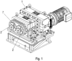
- In der
Figur 1 ist ein Antrieb, aufweisend ein von einem Elektromotor angetriebenen Getriebe 1, eines Extruderschneckenkopplungen 2 aufweisenden Extruders in Schrägansicht dargestellt. - In der
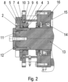
Figur 2 ist ein Querschnitt durch einen eine der Extruderschneckenkopplungen 2 aufweisenden Abtriebsbereich des Extruders dargestellt. - Wie in den Figuren dargestellt, ist die jeweilige Extruderschneckenkopplung 2 formschlüssig, insbesondere mittels einer Steckverzahnung 11, mit einer Welle 13 verbunden.
- Die Extruderschneckenkopplung 2 ist von einer Deckplatte 12 axial begrenzt, welche von einem Schraubenkopf einer Schraube begrenzt wird, die in eine axial gerichtete Gewindebohrung der Welle 13 eingeschraubt ist.
- Auf einem axial hervorragenden Hülsenabschnitt der Extruderschneckenkopplung 2 ist eine Hülse 8 aufgeschoben, die aus gehärtetem Stahl ausgeführt ist. Vorteiligerweise ist somit Reibung reduzierbar. Die Hülse ist auf die Welle 13 aufgepresst und klebeverbunden.
- Die Welle 13 ist drehfest verbunden mit der Extruderschneckenkopplung 2. Die Welle 13 ist über Lager 14, die vorzugsweise nicht gespannt ausgeführt sind, drehbar gelagert. Dabei ist das Lager 14 in einem Lagerflansch 16, insbesondere Gehäuseteil, aufgenommen.
- Der Lagerflansch 16 ist lösbar verbunden mit einem Gehäuseteil 10, welches mit einem Flanschteil 7 lösbar verbunden ist.
- Wellendichtringe 15 sind im Lagerflansch 16 aufgenommen, wobei die Dichtlippen der Wellendichtringe 15 auf einer mit der Welle 13 verbundenen, zweiten, aus gehärtetem Stahl ausgeführten Hülse laufen, die wiederum auf die Welle 13 aufgepresst und klebeverbunden ist.
- Die Lager 14 sind auf der von der Dichtung 15 in axialer Richtung abgewandten Seite angeordnet und somit im mit Schmieröl zumindest teilweise befüllten Innenraum des Getriebes 1 angeordnet, wobei im Innenraum des Getriebes 1 auch miteinander im Eingriff sich befindende Verzahnungsteile angeordnet sind.
- Die Gehäuseteile sind miteinander dicht verbunden zur Bildung des Gehäuses des Getriebes 1.
- Zum Schutz des Innenraums des Getriebes sind zwar die Wellendichtringe 15 als Ölabdichtung fungierend, jedoch ist Extruderschnecken-seitig ein sehr hoher Druck und je nach Betriebszustand sogar Vakuum vorgesehen.
- Daher ist auf der Hülse 8 ein V-Ring aufgenommen, dessen Dichtlippe gegen eine fein bearbeitete Ringfläche des Flanschteils 7 drückt. Das Flanschteil weist zwei umlaufende Ringnuten auf.
- In jeder der beiden Ringnuten ist eine Dichtanordnung aufgenommen, welche einen Basisring 3 aufweist, welcher radial umgeben ist von einem Außenring 4. Der Außenring 4 ist vorzugsweise aus einem ersten Kunststoff ausgeführt und vorzugsweise als O-Ring geformt. Der Außenring 4 ist vorzugsweise stoffschlüssig verbunden mit dem Basisring 3 und derart elastisch verformt, dass er gegen die Wandung der Ringnut gedrückt ist. Auf diese Weise dichtet der Außenring 4 zwischen Basisring 3 und Wandung der Ringnut ab.
- Der Außenring 4 erfüllt somit die Dichtfunktion eines O-Rings. Darüber hinaus ist er auch zum Einbringen einer Schrumpfkraft, also eines Kraftfeldes, welches an allen Umfangspositionen eine, insbesondere die selbe, nach radial innen gerichtet, auf den Basisring 3 wirkende Spannkraft aufweist, geeignet ausgeführt.
- Der Basisring 3 liegt an der Hülse 8 an, wobei der Berührbereich in axialer Richtung keine Punktberührung, sondern eine Linienberührung ist. Hierzu weist der Basisring 3 im Berührbereich einen Zylindermantelflächenabschnitt als Innenfläche auf, welche die Hülse 8 berührt. Der Basisring 3 gleitet somit relativ zur Hülse 8, wenn die Welle 13 in Drehbewegung relativ zum Gehäuse des Getriebes versetzt ist. Zur Verringerung der Reibungsverluste ist als Material des Basisrings 3 ein geeigneter zweiter Werkstoff geeignet gewählt. Der zweite Werkstoff ist vorzugsweise ein Kunststoff oder ein Gummi.
- Zwar wäre als Basisring 3 auch ein mit Teflon, insbesondere also PTFE, insbesondere also Polytetrafluorethylen, beschichteter Messingring verwendbar, jedoch wird vorzugsweise ein Faserverbundwerkstoff verwendet, der ebenfalls ein Material aufweist, das in Paarung mit der Hülse 8, also gehärtetem Stahl, einen sehr niedrigen Reibungskoeffizienten bewirkt.
- Die beiden Ringnuten sind in axialer Richtung voneinander beabstandet. In jeder der Ringnuten ist jeweils eine Dichtung, die den beschriebenen Basisring 3 und stoffschlüssig damit verbunden einen radial den jeweiligen Basisring umgebenden als O-Ring ausgeführten Außenring 4 aufweist.
- Axial zwischen den beiden Ringnuten ist eine weitere, vorzugsweise radial weniger als die beiden Ringnuten ausgedehnte, Ringnut im Flanschteil 7 ausgeführt, in welcher ein Führungsring 6 angeordnet ist.
- Der Führungsring 6 ist aus einem zweiten Werkstoff, insbesondere Kunststoff, wobei der zweite Werkstoff härter als der erste Werkstoff ist.
- Da der Führungsring 6 flächig an der Hülse 8 anliegt, ist eine Zentrierung der Hülse 8 samt der mit der Hülse 8 verbundenen Welle 13 erreicht.
- Denn die Welle 13 ist im Getriebe über die Lager 14 des Getriebes gelagert, so dass das aus dem Getriebe herausstehende Wellenende mit der darauf angeordneten Hülse 8 gleitgelagert ist mittels des Führungsrings 6.
- Der Führungsring 6 sichert also eine Zentrierung der Hülse 8 zur Aufnahmebohrung des Flanschteils 7, so dass die Basisringe 3 keine radialen Querstöße oder Querbewegungen aufnehmen müssen, sondern möglichst konstanten Laufbedingungen ausgesetzt sind.
- Der V-Ring 5 hält Schmutz und von den Extruderschnecken gefördertes Material fern von dem Beriech der Abdichtung zwischen Hülse 8 und Flanschteil 7.
- Die radiale Ausdehnung der den Führungsring 6 aufnehmenden Ringnut ist geringer als die radiale Ausdehnung der jeweiligen die jeweilige Dichtanordnung aufnehmenden Ringnut.
- Bei weiteren erfindungsgemäßen Ausführungsbeispielen wird das Gehäuse, umfassend Flanschteil 7, Gehäuseteil 10 und Lagerflansch 16 aus einer geringeren Anzahl von Teilen ausgeführt, indem Flanschteil 7 und Gehäuseteil 10 einstückig, also einteilig, ausgeführt werden und gegebenenfalls auch der Lagerflansch 16 zusammen mit dem Flanschteil 7 und dem Gehäuseteil 10 aus einem einzigen Stück ausgeführt werden. Auf diese Weise ist eine einfache Herstellung erreichbar, da weniger Teile handzuhaben sind.
- Die erfindungsgemäße Wellenanordnung ist nicht nur für Getriebe sondern auch für andere Vorrichtungen verwendbar, bei denen eine leistungsfähige Abdichtung gegen einen Bereich mit unter hohem oder niedrigem Druck stehenden Material realisiert werden soll und eine Lagerung der Welle nicht vorgespannt ist und/oder weiter in axialer Richtung, also in Richtung der Drehachse der Welle 13, entfernt ist als der halbe Durchmesser der Welle 13 insbesondere im Bereich der Lageraufnahme des am nächsten zur Abdichtung angeordneten Lagers der Welle 13.
-
- 1 Getriebe
- 2 Extruderschneckenkopplung
- 3 Basisring
- 4 Außenring
- 5 V-Ring
- 6 Führungsring
- 7 Flanschteil, insbesondere Gehäuseteil
- 8 Hülse
- 9 Dichtung
- 10 Gehäuseteil
- 11 Verzahnung, insbesondere Steckverzahnung
- 12 Deckplatte
- 13 Welle
- 14 Lager, insbesondere unverspanntes Lager
- 15 Wellendichtring
- 16 Lagerflansch, insbesondere Gehäuseteil
Claims (12)
- Wellenanordnung mit einer relativ zu einem Flanschteil (7) drehbar gelagerten Welle (13), wobei auf die Welle (13) eine Hülse (8) aufgesteckt und drehfest verbunden ist,insbesondere stoffschlüssig und kraftschlüssig verbunden ist, oder wobei die Welle (13) zusammen mit einer Hülse als einziges Teil ausgeführt sind, also einteilig, insbesondere einstückig,wobei das Flanschteil (7) eine erste Ringnut aufweist und eine zur ersten Ringnut koaxial ausgerichtete zweite und/oder dritte Ringnut,wobei in der zweiten und/oder dritten Ringnut eine oder jeweils eine Dichtanordnung angeordnet ist,wobei die jeweilige Dichtanordnung jeweils einen Basisring (3) aufweist, der radial umgeben ist von einem jeweiligen Außenring (4), wobei der Basisring (3) die Hülse (8) berührt und der Außenring (4) die Wandung der zweiten Ringnut berührt,wobei in der ersten Ringnut ein Führungsring (6) zur Zentrierung der Hülse (8) angeordnet ist,wobei der Führungsring (6) sowohl die Hülse (8) als auch die Wandung der Ringnut berührt,wobei auf der von der ersten Ringnut abgewandten Seite der zweiten Ringnut ein V-Ring (5) auf der Hülse (8) aufgenommen ist,wobei der V-Ring (5) von den Ringnuten in axialer Richtung beabstandet ist,wobei der Außenring (4) aus einem elastischen Material ausgeführt ist, so dass der Basisring (3) aufgeschrumpft vorgespannt ist und somit an die Hülse (8) angedrückt ist,dadurch gekennzeichnet, dass die Dichtlippe des V-Rings (5) das Flanschteil (7) berührt,wobei der Außenring (4), der V-Ring (5) und/oder der Führungsring (6) aus FKM, insbesondere also Fluorkarbon-Kautschuk, gefertigt ist,wobei das Flanschteil (7) mit einem einteilig oder mehrteilig ausgeführten Gehäuseteil (10) verbunden ist, in welchem zumindest ein Lager (14) aufgenommen ist, welches die Welle (13) drehbar lagert,wobei der in axialer Richtung gemessene kleinste Abstand der Ringnuten vom Lager (14) größer ist als der halbe Innendurchmesser des Lagers, insbesondere als der halbe Innendurchmesser des an der Welle (13) anliegenden Innenrings des Lagers.
- Wellenanordnung nach Anspruch 1,
dadurch gekennzeichnet, dass
der Führungsring (6) an der Wandung der ersten Ringnut abgestützt ist und zur Hülse (8) hin ein Gleitkontakt zwischen Führungsring (6) und Hülse (8) vorhanden ist. - Wellenanordnung nach einem der vorangegangenen Ansprüche,
dadurch gekennzeichnet, dass
der Außenring (4) als O-Ring ausgeführt ist. - Wellenanordnung nach einem der vorangegangenen Ansprüche,
dadurch gekennzeichnet, dassder Basisring (3) die Hülse (8) flächig berührt,insbesondere also die Berührfläche der Hülse (8) mit dem Basisring (3) ein Zylindermantelabschnitt ist und/oder der Basisring (3) aus einem Polyethylen gefertigt ist, insbesondere aus einem Polyethylen mit ultrahohem Molekulargewicht, oder der Basisring (3) ein mit PTFE, insbesondere Teflon, beschichteter Messingring ist. - Wellenanordnung nach einem der vorangegangenen Ansprüche,
dadurch gekennzeichnet, dassder Führungsring (6) die Hülse (8) flächig berührt,insbesondere also die Berührfläche der Hülse (8) mit dem Führungsring (6) ein Zylindermantelabschnitt ist. - Wellenanordnung nach einem der vorangegangenen Ansprüche,
dadurch gekennzeichnet, dass
der Führungsring (6) aus einem härteren Material als der Basisring (3) ausgeführt ist. - Wellenanordnung nach einem der vorangegangenen Ansprüche,
dadurch gekennzeichnet, dass
die Berührfläche zwischen Hülse (8) und Führungsring (6) in axialer Richtung breiter ist als die Berührfläche zwischen Hülse (8) und Basisring (3). - Wellenanordnung nach einem der vorangegangenen Ansprüche,
dadurch gekennzeichnet, dass
die erste Ringnut radial weniger ausgedehnt ist als die zweite Ringnut. - Wellenanordnung nach einem der vorangegangenen Ansprüche,
dadurch gekennzeichnet, dass
die erste Ringnut in axialer Richtung zwischen der zweiten und der dritten Ringnut angeordnet ist. - Wellenanordnung nach einem der vorangegangenen Ansprüche,
dadurch gekennzeichnet, dass
der Basisring (3) im entspannten Zustand an seiner Innenseite einen Oberflächenabschnitt aufweist, welcher einer Kreiszylindermantelfläche gleicht, insbesondere deren axiale Breite größer als die Hälfte des größten Durchmessers des Ringquerschnitts ist. - Wellenanordnung nach einem der vorangegangenen Ansprüche,
dadurch gekennzeichnet, dassdas Material des V-Rings (5) eine geringere Härte aufweist als das Material des Außenrings (4) und als das Material des Führungsrings (6),und/oder dass die Hülse (8) aus gehärtetem Stahl ausgeführt ist. - Getriebe (1) mit einer Wellenanordnung nach einem der vorangegangenen Ansprüche oder Extruder mit Getriebe (1) mit einer Wellenanordnung nach einem der vorangegangenen Ansprüche, wobei eine Extruderschneckenkopplung (2) mit der Welle (13) drehfest, insbesondere mittels Steckverzahnung, verbunden ist.
Applications Claiming Priority (2)
| Application Number | Priority Date | Filing Date | Title |
|---|---|---|---|
| DE102019007247.2A DE102019007247B3 (de) | 2019-10-18 | 2019-10-18 | Wellenanordnung, Getriebe mit einer Wellenanordnung und Extruder mit Getriebe mit einer Wellenanordnung, mit einer relativ zu einem Flanschteil drehbar gelagerten Welle |
| PCT/EP2020/025431 WO2021073770A1 (de) | 2019-10-18 | 2020-09-24 | Wellenanordnung, getriebe mit einer wellenanordnung und extruder mit getriebe mit einer wellenanordnung, mit einer relativ zu einem flanschteil drehbar gelagerten welle |
Publications (3)
| Publication Number | Publication Date |
|---|---|
| EP4045823A1 EP4045823A1 (de) | 2022-08-24 |
| EP4045823B1 true EP4045823B1 (de) | 2025-02-26 |
| EP4045823C0 EP4045823C0 (de) | 2025-02-26 |
Family
ID=72752862
Family Applications (1)
| Application Number | Title | Priority Date | Filing Date |
|---|---|---|---|
| EP20786450.5A Active EP4045823B1 (de) | 2019-10-18 | 2020-09-24 | Wellenanordnung, getriebe mit einer wellenanordnung und extruder mit getriebe mit einer wellenanordnung, mit einer relativ zu einem flanschteil drehbar gelagerten welle |
Country Status (4)
| Country | Link |
|---|---|
| EP (1) | EP4045823B1 (de) |
| CN (1) | CN114555985B (de) |
| DE (2) | DE102019007247B3 (de) |
| WO (1) | WO2021073770A1 (de) |
Families Citing this family (1)
| Publication number | Priority date | Publication date | Assignee | Title |
|---|---|---|---|---|
| DE102022001889A1 (de) * | 2021-06-15 | 2022-12-15 | Sew-Eurodrive Gmbh & Co Kg | System mit Getriebe und Verfahren zum Herstellen eines Getriebes |
Citations (5)
| Publication number | Priority date | Publication date | Assignee | Title |
|---|---|---|---|---|
| WO1992007207A1 (en) * | 1990-10-11 | 1992-04-30 | Rotoflex, Inc. | Rotary shaft sealing device |
| US7083170B2 (en) * | 2001-04-09 | 2006-08-01 | Carl Freudenberg Kg | Rod or piston primary seal |
| KR20110069955A (ko) * | 2009-12-18 | 2011-06-24 | 현대중공업 주식회사 | 유압공급 로터리유닛의 축정렬장치 |
| JP5101357B2 (ja) * | 2008-03-18 | 2012-12-19 | 三菱重工業株式会社 | 回転機械及び追設リング |
| WO2015064059A1 (ja) * | 2013-10-30 | 2015-05-07 | 三菱電線工業株式会社 | シール材及びそれを用いたシール構造 |
Family Cites Families (3)
| Publication number | Priority date | Publication date | Assignee | Title |
|---|---|---|---|---|
| HU201389B (en) * | 1987-07-10 | 1990-10-28 | Richter Gedeon Vegyeszet | Device for sealed leading axles of large deflection through the connecting branch of closed vessel |
| AT501757B1 (de) * | 2005-06-21 | 2006-11-15 | Erwin F Kopp | Radiale dichtungsvorrichtung |
| US10138942B2 (en) * | 2017-01-11 | 2018-11-27 | Aurora Flight Sciences Corporation | Passive fault-tolerant shaft seal configuration |
-
2019
- 2019-10-18 DE DE102019007247.2A patent/DE102019007247B3/de active Active
-
2020
- 2020-09-24 DE DE102020005857.4A patent/DE102020005857A1/de active Pending
- 2020-09-24 CN CN202080072573.9A patent/CN114555985B/zh active Active
- 2020-09-24 WO PCT/EP2020/025431 patent/WO2021073770A1/de not_active Ceased
- 2020-09-24 EP EP20786450.5A patent/EP4045823B1/de active Active
Patent Citations (6)
| Publication number | Priority date | Publication date | Assignee | Title |
|---|---|---|---|---|
| WO1992007207A1 (en) * | 1990-10-11 | 1992-04-30 | Rotoflex, Inc. | Rotary shaft sealing device |
| US7083170B2 (en) * | 2001-04-09 | 2006-08-01 | Carl Freudenberg Kg | Rod or piston primary seal |
| JP5101357B2 (ja) * | 2008-03-18 | 2012-12-19 | 三菱重工業株式会社 | 回転機械及び追設リング |
| KR20110069955A (ko) * | 2009-12-18 | 2011-06-24 | 현대중공업 주식회사 | 유압공급 로터리유닛의 축정렬장치 |
| KR101335188B1 (ko) * | 2009-12-18 | 2013-11-29 | 현대중공업 주식회사 | 유압공급 로터리유닛의 축정렬장치 |
| WO2015064059A1 (ja) * | 2013-10-30 | 2015-05-07 | 三菱電線工業株式会社 | シール材及びそれを用いたシール構造 |
Also Published As
| Publication number | Publication date |
|---|---|
| DE102019007247B3 (de) | 2020-11-12 |
| WO2021073770A1 (de) | 2021-04-22 |
| DE102020005857A1 (de) | 2021-04-22 |
| BR112022004258A2 (pt) | 2022-05-31 |
| CN114555985B (zh) | 2025-06-06 |
| EP4045823C0 (de) | 2025-02-26 |
| CN114555985A (zh) | 2022-05-27 |
| EP4045823A1 (de) | 2022-08-24 |
Similar Documents
| Publication | Publication Date | Title |
|---|---|---|
| EP2394354B1 (de) | Spindelmotor | |
| EP2286502A2 (de) | Spindelmotor | |
| EP1356221B1 (de) | Ringförmige dichtung | |
| EP0219683B1 (de) | Dichtungsanordnung | |
| DE102009007952A1 (de) | Spindelmotor | |
| EP2457003A1 (de) | Öldrehdurchführung | |
| EP4045823B1 (de) | Wellenanordnung, getriebe mit einer wellenanordnung und extruder mit getriebe mit einer wellenanordnung, mit einer relativ zu einem flanschteil drehbar gelagerten welle | |
| EP0570786B1 (de) | Drehübertrager für Druckmaschinen | |
| DE102017206770A1 (de) | Dichtungsanordnung | |
| EP4158758B1 (de) | Antrieb mit einem gehäuse, einer adapterplatte und einer abdeckhaube | |
| DE102012010789B4 (de) | Getriebe, umfassend zwei Gehäuseteile mit einer zwischengeordneten Dichtung | |
| EP3368801B1 (de) | Anordnung zur wellendichtung | |
| EP2673471B1 (de) | Dichtungselement für kreiskolbenmaschine | |
| EP3966473B1 (de) | Getriebe mit einem gehäuseteil, einer welle, einem ersten deckelteil und einem zweiten deckelteil | |
| DE102022001423A1 (de) | Getriebemotor mit einem ein Getriebe antreibenden Elektromotor | |
| DE102016215211A1 (de) | Radialkolbenmaschine mit Lamellenbremse | |
| EP4341584B1 (de) | Getriebe mit gehäuseteil und hohlwelle | |
| DE102024000667B3 (de) | Getriebe mit Gehäuse | |
| EP4424467B1 (de) | Elektrowerkzeug | |
| DE102024104231B4 (de) | Verdrängerpumpe mit Gleitringdichtung | |
| DE102006031447A1 (de) | Winkelmesseinrichtung | |
| DE102016112053B4 (de) | Achslagerungseinheit mit Laufring und Förderrolle mit einer Achslagerungseinheit mit Laufring | |
| DE102023001764A1 (de) | Adapter, insbesondere für einen ein Getriebe und einen Elektromotor umfassenden Getriebemotor | |
| WO2025131478A1 (de) | Getriebe mit gehäuse | |
| DE102011082682A1 (de) | Lageranordnung mit einer Dichtung, insbesondere für Unterwasser-Anwendungen |
Legal Events
| Date | Code | Title | Description |
|---|---|---|---|
| STAA | Information on the status of an ep patent application or granted ep patent |
Free format text: STATUS: UNKNOWN |
|
| STAA | Information on the status of an ep patent application or granted ep patent |
Free format text: STATUS: THE INTERNATIONAL PUBLICATION HAS BEEN MADE |
|
| PUAI | Public reference made under article 153(3) epc to a published international application that has entered the european phase |
Free format text: ORIGINAL CODE: 0009012 |
|
| STAA | Information on the status of an ep patent application or granted ep patent |
Free format text: STATUS: REQUEST FOR EXAMINATION WAS MADE |
|
| 17P | Request for examination filed |
Effective date: 20220518 |
|
| AK | Designated contracting states |
Kind code of ref document: A1 Designated state(s): AL AT BE BG CH CY CZ DE DK EE ES FI FR GB GR HR HU IE IS IT LI LT LU LV MC MK MT NL NO PL PT RO RS SE SI SK SM TR |
|
| DAV | Request for validation of the european patent (deleted) | ||
| DAX | Request for extension of the european patent (deleted) | ||
| STAA | Information on the status of an ep patent application or granted ep patent |
Free format text: STATUS: EXAMINATION IS IN PROGRESS |
|
| 17Q | First examination report despatched |
Effective date: 20231026 |
|
| REG | Reference to a national code |
Ref country code: DE Ref legal event code: R079 Free format text: PREVIOUS MAIN CLASS: F16J0015320800 Ipc: F16J0015340000 Ref country code: DE Ref legal event code: R079 Ref document number: 502020010502 Country of ref document: DE Free format text: PREVIOUS MAIN CLASS: F16J0015320800 Ipc: F16J0015340000 |
|
| GRAP | Despatch of communication of intention to grant a patent |
Free format text: ORIGINAL CODE: EPIDOSNIGR1 |
|
| STAA | Information on the status of an ep patent application or granted ep patent |
Free format text: STATUS: GRANT OF PATENT IS INTENDED |
|
| GRAJ | Information related to disapproval of communication of intention to grant by the applicant or resumption of examination proceedings by the epo deleted |
Free format text: ORIGINAL CODE: EPIDOSDIGR1 |
|
| STAA | Information on the status of an ep patent application or granted ep patent |
Free format text: STATUS: EXAMINATION IS IN PROGRESS |
|
| GRAP | Despatch of communication of intention to grant a patent |
Free format text: ORIGINAL CODE: EPIDOSNIGR1 |
|
| STAA | Information on the status of an ep patent application or granted ep patent |
Free format text: STATUS: GRANT OF PATENT IS INTENDED |
|
| RIC1 | Information provided on ipc code assigned before grant |
Ipc: F16C 33/74 20060101ALI20240924BHEP Ipc: F16C 33/72 20060101ALI20240924BHEP Ipc: F16C 33/36 20060101ALI20240924BHEP Ipc: F16C 23/08 20060101ALI20240924BHEP Ipc: F16C 21/00 20060101ALI20240924BHEP Ipc: F16C 19/38 20060101ALI20240924BHEP Ipc: F16C 17/02 20060101ALI20240924BHEP Ipc: F16J 15/3236 20160101ALI20240924BHEP Ipc: F16J 15/3208 20160101ALI20240924BHEP Ipc: F16J 15/34 20060101AFI20240924BHEP |
|
| INTG | Intention to grant announced |
Effective date: 20241008 |
|
| INTG | Intention to grant announced |
Effective date: 20241014 |
|
| GRAS | Grant fee paid |
Free format text: ORIGINAL CODE: EPIDOSNIGR3 |
|
| GRAA | (expected) grant |
Free format text: ORIGINAL CODE: 0009210 |
|
| STAA | Information on the status of an ep patent application or granted ep patent |
Free format text: STATUS: THE PATENT HAS BEEN GRANTED |
|
| AK | Designated contracting states |
Kind code of ref document: B1 Designated state(s): AL AT BE BG CH CY CZ DE DK EE ES FI FR GB GR HR HU IE IS IT LI LT LU LV MC MK MT NL NO PL PT RO RS SE SI SK SM TR |
|
| REG | Reference to a national code |
Ref country code: GB Ref legal event code: FG4D Free format text: NOT ENGLISH |
|
| REG | Reference to a national code |
Ref country code: CH Ref legal event code: EP |
|
| REG | Reference to a national code |
Ref country code: DE Ref legal event code: R096 Ref document number: 502020010502 Country of ref document: DE |
|
| REG | Reference to a national code |
Ref country code: IE Ref legal event code: FG4D Free format text: LANGUAGE OF EP DOCUMENT: GERMAN |
|
| U01 | Request for unitary effect filed |
Effective date: 20250314 |
|
| U07 | Unitary effect registered |
Designated state(s): AT BE BG DE DK EE FI FR IT LT LU LV MT NL PT RO SE SI Effective date: 20250321 |
|
| PG25 | Lapsed in a contracting state [announced via postgrant information from national office to epo] |
Ref country code: RS Free format text: LAPSE BECAUSE OF FAILURE TO SUBMIT A TRANSLATION OF THE DESCRIPTION OR TO PAY THE FEE WITHIN THE PRESCRIBED TIME-LIMIT Effective date: 20250526 |
|
| PG25 | Lapsed in a contracting state [announced via postgrant information from national office to epo] |
Ref country code: PL Free format text: LAPSE BECAUSE OF FAILURE TO SUBMIT A TRANSLATION OF THE DESCRIPTION OR TO PAY THE FEE WITHIN THE PRESCRIBED TIME-LIMIT Effective date: 20250226 |
|
| PG25 | Lapsed in a contracting state [announced via postgrant information from national office to epo] |
Ref country code: ES Free format text: LAPSE BECAUSE OF FAILURE TO SUBMIT A TRANSLATION OF THE DESCRIPTION OR TO PAY THE FEE WITHIN THE PRESCRIBED TIME-LIMIT Effective date: 20250226 |
|
| PG25 | Lapsed in a contracting state [announced via postgrant information from national office to epo] |
Ref country code: NO Free format text: LAPSE BECAUSE OF FAILURE TO SUBMIT A TRANSLATION OF THE DESCRIPTION OR TO PAY THE FEE WITHIN THE PRESCRIBED TIME-LIMIT Effective date: 20250526 Ref country code: IS Free format text: LAPSE BECAUSE OF FAILURE TO SUBMIT A TRANSLATION OF THE DESCRIPTION OR TO PAY THE FEE WITHIN THE PRESCRIBED TIME-LIMIT Effective date: 20250626 |
|
| PG25 | Lapsed in a contracting state [announced via postgrant information from national office to epo] |
Ref country code: HR Free format text: LAPSE BECAUSE OF FAILURE TO SUBMIT A TRANSLATION OF THE DESCRIPTION OR TO PAY THE FEE WITHIN THE PRESCRIBED TIME-LIMIT Effective date: 20250226 |
|
| PG25 | Lapsed in a contracting state [announced via postgrant information from national office to epo] |
Ref country code: GR Free format text: LAPSE BECAUSE OF FAILURE TO SUBMIT A TRANSLATION OF THE DESCRIPTION OR TO PAY THE FEE WITHIN THE PRESCRIBED TIME-LIMIT Effective date: 20250527 |
|
| PG25 | Lapsed in a contracting state [announced via postgrant information from national office to epo] |
Ref country code: SM Free format text: LAPSE BECAUSE OF FAILURE TO SUBMIT A TRANSLATION OF THE DESCRIPTION OR TO PAY THE FEE WITHIN THE PRESCRIBED TIME-LIMIT Effective date: 20250226 |
|
| PGFP | Annual fee paid to national office [announced via postgrant information from national office to epo] |
Ref country code: GB Payment date: 20250731 Year of fee payment: 6 |
|
| PG25 | Lapsed in a contracting state [announced via postgrant information from national office to epo] |
Ref country code: CZ Free format text: LAPSE BECAUSE OF FAILURE TO SUBMIT A TRANSLATION OF THE DESCRIPTION OR TO PAY THE FEE WITHIN THE PRESCRIBED TIME-LIMIT Effective date: 20250226 |
|
| PG25 | Lapsed in a contracting state [announced via postgrant information from national office to epo] |
Ref country code: SK Free format text: LAPSE BECAUSE OF FAILURE TO SUBMIT A TRANSLATION OF THE DESCRIPTION OR TO PAY THE FEE WITHIN THE PRESCRIBED TIME-LIMIT Effective date: 20250226 |
|
| U20 | Renewal fee for the european patent with unitary effect paid |
Year of fee payment: 6 Effective date: 20250930 |
|
| PLBE | No opposition filed within time limit |
Free format text: ORIGINAL CODE: 0009261 |
|
| STAA | Information on the status of an ep patent application or granted ep patent |
Free format text: STATUS: NO OPPOSITION FILED WITHIN TIME LIMIT |
|
| 26N | No opposition filed |
Effective date: 20251127 |