EP4046128B1 - Verfahren für nicht-lokales bild-demosaicing und zugehörige vorrichtung - Google Patents
Verfahren für nicht-lokales bild-demosaicing und zugehörige vorrichtung Download PDFInfo
- Publication number
- EP4046128B1 EP4046128B1 EP21839602.6A EP21839602A EP4046128B1 EP 4046128 B1 EP4046128 B1 EP 4046128B1 EP 21839602 A EP21839602 A EP 21839602A EP 4046128 B1 EP4046128 B1 EP 4046128B1
- Authority
- EP
- European Patent Office
- Prior art keywords
- patches
- similar
- initial
- patch
- pixel
- Prior art date
- Legal status (The legal status is an assumption and is not a legal conclusion. Google has not performed a legal analysis and makes no representation as to the accuracy of the status listed.)
- Active
Links
Images



Classifications
-
- G—PHYSICS
- G06—COMPUTING OR CALCULATING; COUNTING
- G06T—IMAGE DATA PROCESSING OR GENERATION, IN GENERAL
- G06T3/00—Geometric image transformations in the plane of the image
- G06T3/40—Scaling of whole images or parts thereof, e.g. expanding or contracting
- G06T3/4015—Image demosaicing, e.g. colour filter arrays [CFA] or Bayer patterns
-
- G—PHYSICS
- G06—COMPUTING OR CALCULATING; COUNTING
- G06T—IMAGE DATA PROCESSING OR GENERATION, IN GENERAL
- G06T3/00—Geometric image transformations in the plane of the image
- G06T3/40—Scaling of whole images or parts thereof, e.g. expanding or contracting
- G06T3/4007—Scaling of whole images or parts thereof, e.g. expanding or contracting based on interpolation, e.g. bilinear interpolation
-
- G—PHYSICS
- G06—COMPUTING OR CALCULATING; COUNTING
- G06T—IMAGE DATA PROCESSING OR GENERATION, IN GENERAL
- G06T3/00—Geometric image transformations in the plane of the image
- G06T3/40—Scaling of whole images or parts thereof, e.g. expanding or contracting
- G06T3/403—Edge-driven scaling; Edge-based scaling
-
- G—PHYSICS
- G06—COMPUTING OR CALCULATING; COUNTING
- G06T—IMAGE DATA PROCESSING OR GENERATION, IN GENERAL
- G06T5/00—Image enhancement or restoration
- G06T5/70—Denoising; Smoothing
-
- G—PHYSICS
- G06—COMPUTING OR CALCULATING; COUNTING
- G06V—IMAGE OR VIDEO RECOGNITION OR UNDERSTANDING
- G06V10/00—Arrangements for image or video recognition or understanding
- G06V10/70—Arrangements for image or video recognition or understanding using pattern recognition or machine learning
- G06V10/74—Image or video pattern matching; Proximity measures in feature spaces
- G06V10/761—Proximity, similarity or dissimilarity measures
-
- G—PHYSICS
- G06—COMPUTING OR CALCULATING; COUNTING
- G06T—IMAGE DATA PROCESSING OR GENERATION, IN GENERAL
- G06T2207/00—Indexing scheme for image analysis or image enhancement
- G06T2207/10—Image acquisition modality
- G06T2207/10024—Color image
Definitions
- the present application relates to a method for demosaicing an image.
- the method applies in particular to the demosaicing of images whose components are arranged according to a Bayer pattern in the RGB domain.
- An image obtained by a multi-spectral matrix sensor is generally mosaicked.
- An image is for example acquired in the form of pixels with one color component or “single color luminescence” in English and transformed by demosaicing into pixels with several spectral bands or “multiple color luminescence” in English.
- the initial image is thus formed of a set of pixels where each pixel of the image corresponds only to one spectral band among the spectral bands that can be acquired on other pixels of the multi-spectral matrix sensor, each pixel of the multi-spectral matrix sensor acquiring only part of the multi-spectral information.
- a typical case is that of sensors organized according to the Bayer matrix, which is composed of green filters at 50% and red and blue filters at 25% each.
- each square group of four pixels has two green pixels on the diagonal, and one red and one blue pixel on the other diagonal.
- the demosaicing therefore aims to interpolate the two missing values among the red, the green, and the blue, for each pixel of the initial image.
- the object of the invention is to propose a method for demosaicing images that is improved compared to the state of the art.
- the predetermined reference patches are distributed so as to cover a determined proportion of the image.
- the similar patches when determining the covariance matrix of the set of similar patches, comprise initial spectral bands and intermediate spectral bands, these intermediate spectral bands being derived from a prior demosaicing by interpolation linear applied to the initial image.
- the determination of said set of patches similar to each reference patch is determined by a similarity function applied to an intermediate image resulting from prior demosaicing by linear interpolation of the initial image.
- the similar patches when determining the covariance matrix of the set of similar patches, comprise initial spectral bands and intermediate spectral bands, these intermediate spectral bands being derived from a prior demosaicing by interpolation linear and a prior denoising applied to the initial image.
- the determination of said set of patches similar to each reference patch is determined by a similarity function applied to an intermediate image resulting from prior demosaicing by linear interpolation and prior denoising of the initial image.
- the denoising may consist of a local denoising function applied to each patch and a function of said set of patches similar to the patch considered.
- the spectral bands correspond to RGB or YUV color space.
- the spectral bands correspond to the RGB colorimetric space and the pixels of the initial image are organized according to a Bayer pattern.
- the aggregation of the estimates of the interpolated spectral bands is carried out by a calculation of an average of these estimates of interpolated spectral bands.
- the same decomposition of the covariance matrix into blocks takes place which are stored and reused for all these similar patches having the same phasing.
- the present disclosure also relates to a computer program product, comprising code instructions for implementing the method according to the preceding description, when it is executed by a computer.
- the present disclosure also relates to an image processing device comprising a computer, characterized in that it is configured to implement the method according to the preceding description.
- this method makes it possible to obtain improved results in terms of quality of restitution and robustness to noise.
- the method according to the invention makes it possible in particular to reduce or even eliminate inaccuracies of the iridescent type.
- the invention makes it possible to improve the quality of a demosaic image obtained from a sensor provided with a Bayer filter.
- the method described also makes it possible to take account of the spatial distribution in the variation in precision, which is not necessarily isotropic, thanks to the covariance matrix.
- the method is indeed advantageously non-local and is based on the similarities between a patch of image pixels and a set of similar patches, which may have close or distant positions in the initial image.
- the initial images can be composed of pixels belonging to a colorimetric space, for example to three colors.
- the initial images can also be radar images.
- the pixels of the initial image each correspond to an initial spectral band.
- the demosaicing method according to the invention can be implemented by an image processing device 1 shown schematically in figure 5 , comprising a computer 10 which can be for example a processor equipped or not with a graphics card, a microprocessor or a microcontroller.
- the image processing device 1 notably comprises a communication interface with at least one sensor supplying initial images.
- the image processing device 1 can also comprise a memory 11 storing code instructions executed by the computer for implementing the method, as well as the data necessary for implementing the processing of one or more images.
- the initial image is formed of a set of pixels each having an initial spectral band corresponding for example to a specific value for a color detected from among a set of colors of the multi-spectral sensor.
- the multi-spectral sensor can for example be of the RGB type where spectral bands detected in each pixel of the image are red, green or blue, the sensor being equipped for this purpose with a matrix of colored filters adapted to allow only part of the light spectrum to pass for each pixel of the matrix.
- the detected spectral bands correspond to the YUV colorimetric space.
- the demosaicing method can be applied to several spectral bands, such as for example in the colorimetric space, the values of certain pixels being available in the form of the initial spectral band while other missing ones are to be interpolated.
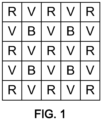
- the sensor generating the initial image may, for example, have a Bayer configuration, as shown in figure 1 , in the RGB color space.
- Each green pixel is represented by the letter "G”
- each red pixel is represented by the letter "R”
- each blue pixel is represented by the letter "B”.
- the components of the color space are red, green and blue. 50% of the pixels correspond to the green spectral band, 25% of the pixels correspond to the red spectral band and 25% of the pixels correspond to the blue spectral band.
- the pixels are organized so that in a square of two pixels on a side, the two pixels on one diagonal correspond to the green spectral band while the other diagonal includes a red pixel and a blue pixel.
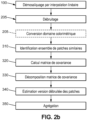
- the demosaicing method comprises for example prior demosaicing by linear interpolation 100 of the initial image, making it possible to calculate intermediate spectral bands.
- the spectral bands correspond to the RGB colorimetric space, it is a question of associating with each pixel the two missing spectral bands among red, green and blue.
- the intermediate spectral bands are here an intermediate means of calculation.
- This demosaicing by linear interpolation 100 can be chosen from demosaicing methods known to those skilled in the art.
- demosaicing by linear interpolation can be implemented by means of the Hamilton-Adams algorithm, as described in the patent US5,652,621 .
- the demosaicing method may further comprise a denoising processing 200 applied at the output of the demosaicing by linear interpolation 100 to obtain the intermediate spectral bands.
- This denoising processing 200 can be chosen from among the denoising processings known to those skilled in the art, such as for example an algorithm of the NL-Bayes type, as described in the article by M. Lebrun et al., “Implementation of the “Non-Local Bayes” (NL-Bayes) Image Denoising Algorithm” .
- the NL-Bayes denoising algorithm comprises for example the repetition twice in succession of an identification of a set of similar patches of the image for the calculation of a covariance matrix of the set of similar patches, d 'an estimate of a denoised version, from the covariance matrix and an aggregation to obtain a denoised image.
- the denoising is for example implemented twice in succession, the first time on the image obtained at the end of the demosaicing by linear interpolation and the second time on the denoised image.
- the denoising algorithm carries out for example a patch processing of the image.
- a patch is a square-shaped piece of the image comprising a subset of pixels of the image.
- a patch can comprise between 2 and 10 pixels per side and typically comprises between 3 and 5.
- the demosaicing method for example then comprises a set of steps implemented on at least one patch of the image and preferably on all of the patches of the image considered successively.
- Reference patches are for example determined in advance and carry out overlaps between two successive patches, so as to cover the whole of the image.
- the reference patches can for example be contiguous or not.
- the adjoining reference patches can for example overlap or not.
- the nonadjoining reference patches can for example be more or less spaced from each other.
- an uncovered area of the image is for example less than 50% of the image or even less than 25% of the image, or even less than 5% of the image.
- the choice of the proportion of the image covered by the reference patches and their possible overlapping will be optimized according to the use cases.
- the proportion of the image, covered by the reference patches is for example between 50% and 100%.
- a step 310 of identifying a set of similar patches of the image to the reference patch is carried out.
- the identification step 310 of a set of patches of the image similar to the patch considered can be implemented by calculating a distance between the patch considered and each of the patches of the image belonging to a neighborhood of the patch considered, the neighborhood being defined as a portion of the image of size n x n, where n is a number of pixels strictly greater than the number of pixels k on one side of a patch, and less than or equal to the number of pixels on a plus small side of the picture.
- the distance can be calculated over all of the patches P and Q concerned or only a portion thereof, for example a horizontal or vertical band.
- the distance can be calculated in native radiometry, that is to say from the initial spectral bands in the initial image.
- this space is RGB space
- the normalized quadratic distance can be calculated, as the sum, over all the pixels i of the patches P and Q, of the distance ( P i , R - Q i,R ) 2 + ( P i,G - Q i,G ) 2 + ( P i,B - Q i,B ) 2 where the index R, G, B respectively corresponds to the component in the red, green or blue color, of patch P or Q, respectively.
- the initial image can be converted beforehand during a step 205 into another colorimetric space, and the normalized quadratic distance can be calculated in this space.
- the normalized quadratic distance can be calculated on the only luminance component Y.
- the distance is for example compared with a determined threshold, below which the patches are considered to be similar.
- the identification of a set of patches similar to the patch considered may comprise the application of a principal component analysis of the image in native or transformed coordinates, and the calculation of a distance (p .eg Euclidean) on the most significant components resulting from this analysis.
- similar patches can be determined and stored during a prior denoising step.
- the demosaicing method comprises a following step 320 of calculating a covariance matrix of all the patches similar to the reference patch.
- the covariance matrix can be calculated on the values of the pixels of the patches in the initial spectral bands represented in the initial image, or in other words in native radiometry.
- the covariance matrix can also be calculated on the pixels of an intermediate image obtained by demosaicing by linear interpolation, as shown in figure 2a and possibly supplemented by denoising, as shown in figure 2b .
- a covariance matrix, calculated during a previous processing, can optionally be reused.
- Each patch of k pixels on a side in the initial image is represented as a vector whose first k 2 terms correspond to a spectral band, for example the color red, the following k 2 terms correspond to another spectral band, for example the green color, and the k last 2 terms correspond to a third spectral band, for example the color blue.
- the covariance matrix therefore quantifies the covariance of the pixel values of similar patches.
- initial spectral band for an image with several spectral bands.
- the locations of pixels with an available or missing character depend on the phasing of the patch.
- To determine the phasing of a patch consider the location on the array sensor of a corresponding patch in the initial image. In the case for example of a Bayer pattern, there are four possible phasings of which two examples are represented on the figures 3a and 3b .
- the pixels having an initial value according to the respective red, green or blue component are represented respectively by the letter R, G, B.
- the picture 3a corresponds to a phasing where the pixel located at the top left of the patch is expressed in the green component of the original image
- the figure 3b corresponds to a phasing where the pixel located at the top left of the patch is the pixel expressed in the red component.
- the demosaicing method then comprises in step 330, for each similar patch of said set of similar patches, a calculation of estimates of the interpolated spectral bands, a function of a block decomposition of the covariance matrix, where the decomposition into four blocks is a function of the phasing of each similar patch.
- the demosaicing method then comprises an aggregation step 350 in which estimates of the interpolated spectral bands for patch pixels belonging to different sets of similar patches in relation to different reference patches.
- aggregation we mean the combination of different measurements into a single variable, either by simple addition of the values obtained, or by addition of the weighted values.
- the aggregation is implemented for example by calculating an average of the estimates made for a pixel and a component.
- the set of interpolated spectral bands is thus obtained.
- the demosaicized image according to the invention presents an improved quality and a reduction significant or even an absence of iridescence, in particular for applications requiring observation at high altitude such as earth observation.
- x ⁇ m has r g max P x m x m
- ⁇ mm ⁇ md ⁇ dm ⁇ d HAS B VS D
- x m there ⁇ m + ⁇ md ⁇ d ⁇ 1 there d ⁇ there ⁇ d
- ⁇ d denoised is the block of the covariance matrix calculated on the available denoised data
- I is the identity matrix
- ⁇ 2 is the variance of the noise. It can be shown that ⁇ md is unchanged in this case.
- x m there ⁇ m + ⁇ md ⁇ d denoised + ⁇ 2 I ⁇ 1 there d ⁇ there ⁇ d
Landscapes
- Engineering & Computer Science (AREA)
- Theoretical Computer Science (AREA)
- Physics & Mathematics (AREA)
- General Physics & Mathematics (AREA)
- Computer Vision & Pattern Recognition (AREA)
- Databases & Information Systems (AREA)
- Artificial Intelligence (AREA)
- Computing Systems (AREA)
- Health & Medical Sciences (AREA)
- Evolutionary Computation (AREA)
- General Health & Medical Sciences (AREA)
- Medical Informatics (AREA)
- Software Systems (AREA)
- Multimedia (AREA)
- Image Processing (AREA)
- Color Television Image Signal Generators (AREA)
Claims (15)
- Verfahren zur Entfernung des Mosaikeffekts, das auf ein Ausgangsbild angewendet wird, das Pixel aufweist, die jeweils einem Ausgangsspektralband entsprechen, um ein Bild mit entferntem Mosaikeffekt mit mehreren Spektralbändern zu erhalten, das Pixel aufweist, die jeweils dem Ausgangsspektralband oder einem interpolierten Spektralband entsprechen,
dadurch gekennzeichnet, dass es Folgendes umfasst:- auf der Grundlage einer Vielzahl von vorbestimmten Referenzpatches und für jeden Referenzpatch aus der Vielzahl von Referenzpatches:∘ eine Bestimmung (310) eines Satzes von Patches, die dem Referenzpatch ähnlich sind,∘ eine Bestimmung (320) einer Kovarianzmatrix des Satzes ähnlicher Patches, und∘ für jeden ähnlichen Patch aus dem Satz ähnlicher Patches eine Berechnung von Schätzwerten der interpolierten Spektralbänder, die von einer Blockzerlegung der Kovarianzmatrix (340) abhängt, wobei die Zerlegung in vier Blöcke von der Phasenlage jedes ähnlichen Patches abhängt, und- eine Bestimmung der interpolierten Spektralbänder durch eine Aggregation (350) der Schätzwerte der interpolierten Spektralbänder, wobei die Schätzwerte der interpolierten Spektralbänder für jeden Pixel aggregiert werden. - Verfahren nach Anspruch 1, wobei die vorbestimmten Referenzpatches so verteilt werden, dass sie einen bestimmten Anteil des Bildes abdecken.
- Verfahren nach Anspruch 1 oder 2, wobei bei der Bestimmung der Kovarianzmatrix des Satzes ähnlicher Patches die ähnlichen Patches Ausgangsspektralbänder und Zwischen-Spektralbänder umfassen, wobei die Zwischen-Spektralbänder aus einer vorherigen Entfernung des Mosaikeffekts durch lineare Interpolation stammen, die auf das Ausgangsbild angewendet wird.
- Verfahren nach dem vorhergehenden Anspruch, wobei die Bestimmung (310) des Satzes von Patches, die jedem Referenzpatch ähnlich sind, durch eine Ähnlichkeitsfunktion bestimmt wird, die auf ein Zwischenbild angewendet wird, das aus einer vorherigen Entfernung des Mosaikeffekts durch lineare Interpolation des Ausgangsbildes resultiert.
- Verfahren nach Anspruch 1 oder 2, wobei bei der Bestimmung der Kovarianzmatrix des Satzes ähnlicher Patches die ähnlichen Patches Ausgangsspektralbänder und Zwischen-Spektralbänder umfassen, wobei die Zwischen-Spektralbänder aus einer vorherigen Entfernung des Mosaikeffekts durch lineare Interpolation und einer vorherigen Rauschunterdrückung stammen, die auf das Ausgangsbild angewendet wurden.
- Verfahren nach dem vorhergehenden Anspruch, wobei die Bestimmung (310) des Satzes von Patches, die jedem Referenzpatch ähnlich sind, durch eine Ähnlichkeitsfunktion bestimmt wird, die auf ein Zwischenbild angewendet wird, das aus einer vorherigen Entfernung des Mosaikeffekts durch lineare Interpolation (100) und der vorherigen Rauschunterdrückung des Ausgangsbildes resultiert.
- Verfahren nach Anspruch 5 oder 6, wobei die Rauschunterdrückung aus einer lokalen Rauschunterdrückungsfunktion besteht, die auf jeden Patch angewendet wird und eine Funktion der genannten Menge von Patches ist, die dem betrachteten Patch ähnlich sind.
- Verfahren nach einem der Ansprüche 1 bis 7, wobei die Spektralbänder dem RGB- oder YUV-Farbraum entsprechen.
- Verfahren nach einem der Ansprüche 1 bis 8, wobei die Spektralbänder dem RGB-Farbraum entsprechen und die Pixel des Ausgangsbildes nach einem Bayer-Muster angeordnet sind.
- Verfahren nach einem der vorhergehenden Ansprüche, wobei die Aggregation (350) der Schätzwerte der interpolierten Spektralbänder durch eine Berechnung eines Mittelwerts dieser Schätzwerte der interpolierten Spektralbänder durchgeführt wird.
- Verfahren nach einem der vorhergehenden Ansprüche, wobei die phasenabhängige Zerlegung des ähnlichen Patches in vier Blöcke von dem Paar (L,C) abhängt, das dem L-ten Pixel und dem C-ten Pixel des ähnlichen Patches entspricht, wobei für jeden Wert der Matrix in der Zeile L und der Spalte C gilt, je nachdem, ob es sich um Folgendes handelt:- ein Pixel L, das einem Ausgangsspektralband entspricht, und ein Pixel C, das einem Ausgangsspektralband entspricht, wird einem ersten Block Σdd zugeordnet,- ein Pixel L, das nicht einem Ausgangsspektralband entspricht, und ein Pixel C, das einem Ausgangsspektralband entspricht, wird einem zweiten Block Σmd zugeordnet,- ein Pixel L, das einem Ausgangsspektralband entspricht, und ein Pixel C, das keinem Ausgangsspektralband entspricht, wird einem dritten Block Σdm zugeordnet,
oder- ein Pixel L, das nicht einem Ausgangsspektralband entspricht, und ein Pixel C, das nicht einem Ausgangsspektralband entspricht, wird einem vierten Block Σmm zugewiesen. - Verfahren nach dem vorhergehenden Anspruch, wobei für jeden ähnlichen Patch in dem Satz von ähnlichen Patches die Berechnung der Schätzwerte der interpolierten Spektralbänder wie folgt durchgeführt wird:
 - xm ist der Vektor der Schätzwerte der interpolierten Spektralbänder des ähnlichen Patches,-
y m ist der Vektor der Mittelwerte der Pixel der Patches des Satzes ähnlicher Patches, wobei die Pixel betrachtet werden, die nicht einem Ausgangsspektralband entsprechen,- yd ist der Vektor der Pixel, die einem Ausgangsspektralband in dem genannten ähnlichen Patch entsprechen,-y d ist der Vektor der Mittelwerte der Pixel in den Patches des Satzes ähnlicher Patches, wobei Pixel berücksichtigt werden, die einem Ausgangsspektralband entsprechen,- - Σ md ist der zweite Block.
 - Verfahren nach dem vorhergehenden Anspruch, wobei bei der Berechnung der Schätzwerte der interpolierten Spektralbänder für ähnliche Patches mit demselben Phasenverlauf dieselbe Zerlegung der Kovarianzmatrix in Blöcke erfolgt, die gespeichert und für alle diese ähnlichen Patches mit demselben Phasenverlauf wiederverwendet werden.
- Computerprogrammprodukt, das Codeanweisungen zur Durchführung des Verfahrens nach einem der vorhergehenden Ansprüche enthält, wenn es von einem Rechner ausgeführt wird.
- Bildverarbeitungsvorrichtung, umfassend einen Rechner (11), dadurch gekennzeichnet, dass dieser dazu ausgebildet ist, das Verfahren nach einem der Ansprüche 1 bis 13 auszuführen.
Applications Claiming Priority (2)
| Application Number | Priority Date | Filing Date | Title |
|---|---|---|---|
| FR2013027A FR3117651B1 (fr) | 2020-12-10 | 2020-12-10 | Procédé de démosaïquage non-local d’une image et dispositif associé |
| PCT/FR2021/052157 WO2022123145A1 (fr) | 2020-12-10 | 2021-12-01 | Procédé de démosaïquage non-local d'une image et dispositif associé |
Publications (3)
| Publication Number | Publication Date |
|---|---|
| EP4046128A1 EP4046128A1 (de) | 2022-08-24 |
| EP4046128B1 true EP4046128B1 (de) | 2023-09-06 |
| EP4046128C0 EP4046128C0 (de) | 2023-09-06 |
Family
ID=75438880
Family Applications (1)
| Application Number | Title | Priority Date | Filing Date |
|---|---|---|---|
| EP21839602.6A Active EP4046128B1 (de) | 2020-12-10 | 2021-12-01 | Verfahren für nicht-lokales bild-demosaicing und zugehörige vorrichtung |
Country Status (5)
| Country | Link |
|---|---|
| US (1) | US11816812B2 (de) |
| EP (1) | EP4046128B1 (de) |
| ES (1) | ES2965026T3 (de) |
| FR (1) | FR3117651B1 (de) |
| WO (1) | WO2022123145A1 (de) |
Families Citing this family (3)
| Publication number | Priority date | Publication date | Assignee | Title |
|---|---|---|---|---|
| US12602738B2 (en) * | 2023-03-30 | 2026-04-14 | Apple Inc. | Noise reduction circuit with demosaic processing |
| CN118158551B (zh) * | 2024-04-30 | 2024-07-23 | 合肥埃科光电科技股份有限公司 | 一种基于fpga的去马赛克方法、系统及介质 |
| CN119963434B (zh) * | 2024-12-27 | 2025-10-24 | 浙江大学 | 一种水产养殖生产场景的高光谱图像降噪方法 |
Family Cites Families (4)
| Publication number | Priority date | Publication date | Assignee | Title |
|---|---|---|---|---|
| US5629734A (en) | 1995-03-17 | 1997-05-13 | Eastman Kodak Company | Adaptive color plan interpolation in single sensor color electronic camera |
| US5652621A (en) | 1996-02-23 | 1997-07-29 | Eastman Kodak Company | Adaptive color plane interpolation in single sensor color electronic camera |
| US20090295934A1 (en) * | 2008-05-27 | 2009-12-03 | The Hong Kong University Of Science And Technology | Color demosaicking using direction similarity in color difference spaces |
| JP7030493B2 (ja) * | 2017-11-30 | 2022-03-07 | キヤノン株式会社 | 画像処理装置、画像処理方法およびプログラム |
-
2020
- 2020-12-10 FR FR2013027A patent/FR3117651B1/fr active Active
-
2021
- 2021-12-01 ES ES21839602T patent/ES2965026T3/es active Active
- 2021-12-01 EP EP21839602.6A patent/EP4046128B1/de active Active
- 2021-12-01 US US18/253,370 patent/US11816812B2/en active Active
- 2021-12-01 WO PCT/FR2021/052157 patent/WO2022123145A1/fr not_active Ceased
Also Published As
| Publication number | Publication date |
|---|---|
| ES2965026T3 (es) | 2024-04-10 |
| EP4046128C0 (de) | 2023-09-06 |
| FR3117651A1 (fr) | 2022-06-17 |
| EP4046128A1 (de) | 2022-08-24 |
| WO2022123145A1 (fr) | 2022-06-16 |
| FR3117651B1 (fr) | 2022-12-16 |
| US20230325970A1 (en) | 2023-10-12 |
| US11816812B2 (en) | 2023-11-14 |
Similar Documents
| Publication | Publication Date | Title |
|---|---|---|
| EP4046128B1 (de) | Verfahren für nicht-lokales bild-demosaicing und zugehörige vorrichtung | |
| EP1482724B1 (de) | Bildverarbeitungsverfahren für numerische Bilder mit Belichtungskorrektur durch Erkennung von Hautbereichen des Gegenstandes | |
| Pei et al. | Nighttime haze removal using color transfer pre-processing and dark channel prior | |
| Zhou et al. | Deep residual network for joint demosaicing and super-resolution | |
| US20120307116A1 (en) | Learning of Image Processing Pipeline for Digital Imaging Devices | |
| US7986834B2 (en) | Method and apparatus for color image correction | |
| EP2426639A1 (de) | Demosaicing-Verfahren für ein digitales Rohbild, entsprechendes Computerprogramm und entsprechende Bild- oder Grafikerzeugungsschaltung | |
| US7528991B2 (en) | Method of generating a mask image of membership of single pixels to certain chromaticity classes and of adaptive improvement of a color image | |
| Sadeghipoor et al. | Optimum spectral sensitivity functions for single sensor color imaging | |
| EP4364083B1 (de) | Verfahren zur durchführung einer nichtlokalen demosaicing eines bildes und zugehörige vorrichtung | |
| Ružić et al. | Virtual restoration of the Ghent Altarpiece using crack detection and inpainting | |
| EP3206161B1 (de) | Verfahren zur bestimmung eines farbwerts eines objekts auf einem bild | |
| Yang et al. | Color image contrast enhancement by co-occurrence histogram equalization and dark channel prior | |
| CN117596488A (zh) | 相机传感器到传感器颜色空间映射 | |
| CN110807746B (zh) | 一种基于细节内嵌注入卷积神经网络高光谱图像锐化方法 | |
| BE1021013B1 (fr) | Procede et systeme pour ameliorer la qualite d'images en couleur. | |
| Yan et al. | Channel-by-channel demosaicking networks with embedded spectral correlation | |
| US12217433B2 (en) | Adaptive auto white balancing | |
| Fierro et al. | An automatic color correction method inspired by the Retinex and opponent colors theories | |
| Twinkle et al. | Edge Preserving Multiplicative Noise Removal of SAR Images Through Convolutional Neural Network and Anisotropic Diffusion | |
| US11580729B2 (en) | Agricultural pattern analysis system | |
| CN109766831A (zh) | 一种道路色带识别方法、装置、计算机设备、及存储介质 | |
| Akhavan et al. | A new combining learning method for color constancy | |
| WO2026022158A1 (fr) | Procédé de détermination d'une texture d'un objet et dispositifs associés pour aider à la visualisation de la rugosité de surface | |
| Gupta et al. | Demosaicing of Multispectral Imaging Camera data using Neural Networks |
Legal Events
| Date | Code | Title | Description |
|---|---|---|---|
| STAA | Information on the status of an ep patent application or granted ep patent |
Free format text: STATUS: UNKNOWN |
|
| STAA | Information on the status of an ep patent application or granted ep patent |
Free format text: STATUS: THE INTERNATIONAL PUBLICATION HAS BEEN MADE |
|
| PUAI | Public reference made under article 153(3) epc to a published international application that has entered the european phase |
Free format text: ORIGINAL CODE: 0009012 |
|
| STAA | Information on the status of an ep patent application or granted ep patent |
Free format text: STATUS: REQUEST FOR EXAMINATION WAS MADE |
|
| 17P | Request for examination filed |
Effective date: 20220502 |
|
| AK | Designated contracting states |
Kind code of ref document: A1 Designated state(s): AL AT BE BG CH CY CZ DE DK EE ES FI FR GB GR HR HU IE IS IT LI LT LU LV MC MK MT NL NO PL PT RO RS SE SI SK SM TR |
|
| RIN1 | Information on inventor provided before grant (corrected) |
Inventor name: GUILLAUME, LAURENT |
|
| GRAP | Despatch of communication of intention to grant a patent |
Free format text: ORIGINAL CODE: EPIDOSNIGR1 |
|
| STAA | Information on the status of an ep patent application or granted ep patent |
Free format text: STATUS: GRANT OF PATENT IS INTENDED |
|
| INTG | Intention to grant announced |
Effective date: 20230405 |
|
| RAP3 | Party data changed (applicant data changed or rights of an application transferred) |
Owner name: AIRBUS DEFENCE AND SPACE SAS |
|
| RIN1 | Information on inventor provided before grant (corrected) |
Inventor name: GUILLAUME, LAURENT |
|
| GRAS | Grant fee paid |
Free format text: ORIGINAL CODE: EPIDOSNIGR3 |
|
| GRAA | (expected) grant |
Free format text: ORIGINAL CODE: 0009210 |
|
| STAA | Information on the status of an ep patent application or granted ep patent |
Free format text: STATUS: THE PATENT HAS BEEN GRANTED |
|
| AK | Designated contracting states |
Kind code of ref document: B1 Designated state(s): AL AT BE BG CH CY CZ DE DK EE ES FI FR GB GR HR HU IE IS IT LI LT LU LV MC MK MT NL NO PL PT RO RS SE SI SK SM TR |
|
| DAV | Request for validation of the european patent (deleted) | ||
| DAX | Request for extension of the european patent (deleted) | ||
| REG | Reference to a national code |
Ref country code: GB Ref legal event code: FG4D Free format text: NOT ENGLISH |
|
| REG | Reference to a national code |
Ref country code: CH Ref legal event code: EP |
|
| REG | Reference to a national code |
Ref country code: DE Ref legal event code: R096 Ref document number: 602021005001 Country of ref document: DE |
|
| REG | Reference to a national code |
Ref country code: IE Ref legal event code: FG4D Free format text: LANGUAGE OF EP DOCUMENT: FRENCH |
|
| U01 | Request for unitary effect filed |
Effective date: 20231003 |
|
| U07 | Unitary effect registered |
Designated state(s): AT BE BG DE DK EE FI FR IT LT LU LV MT NL PT SE SI Effective date: 20231012 |
|
| PG25 | Lapsed in a contracting state [announced via postgrant information from national office to epo] |
Ref country code: GR Free format text: LAPSE BECAUSE OF FAILURE TO SUBMIT A TRANSLATION OF THE DESCRIPTION OR TO PAY THE FEE WITHIN THE PRESCRIBED TIME-LIMIT Effective date: 20231207 |
|
| PG25 | Lapsed in a contracting state [announced via postgrant information from national office to epo] |
Ref country code: RS Free format text: LAPSE BECAUSE OF FAILURE TO SUBMIT A TRANSLATION OF THE DESCRIPTION OR TO PAY THE FEE WITHIN THE PRESCRIBED TIME-LIMIT Effective date: 20230906 Ref country code: NO Free format text: LAPSE BECAUSE OF FAILURE TO SUBMIT A TRANSLATION OF THE DESCRIPTION OR TO PAY THE FEE WITHIN THE PRESCRIBED TIME-LIMIT Effective date: 20231206 Ref country code: HR Free format text: LAPSE BECAUSE OF FAILURE TO SUBMIT A TRANSLATION OF THE DESCRIPTION OR TO PAY THE FEE WITHIN THE PRESCRIBED TIME-LIMIT Effective date: 20230906 Ref country code: GR Free format text: LAPSE BECAUSE OF FAILURE TO SUBMIT A TRANSLATION OF THE DESCRIPTION OR TO PAY THE FEE WITHIN THE PRESCRIBED TIME-LIMIT Effective date: 20231207 |
|
| U20 | Renewal fee for the european patent with unitary effect paid |
Year of fee payment: 3 Effective date: 20231227 |
|
| PG25 | Lapsed in a contracting state [announced via postgrant information from national office to epo] |
Ref country code: IS Free format text: LAPSE BECAUSE OF FAILURE TO SUBMIT A TRANSLATION OF THE DESCRIPTION OR TO PAY THE FEE WITHIN THE PRESCRIBED TIME-LIMIT Effective date: 20240106 |
|
| REG | Reference to a national code |
Ref country code: ES Ref legal event code: FG2A Ref document number: 2965026 Country of ref document: ES Kind code of ref document: T3 Effective date: 20240410 |
|
| PG25 | Lapsed in a contracting state [announced via postgrant information from national office to epo] |
Ref country code: SM Free format text: LAPSE BECAUSE OF FAILURE TO SUBMIT A TRANSLATION OF THE DESCRIPTION OR TO PAY THE FEE WITHIN THE PRESCRIBED TIME-LIMIT Effective date: 20230906 Ref country code: RO Free format text: LAPSE BECAUSE OF FAILURE TO SUBMIT A TRANSLATION OF THE DESCRIPTION OR TO PAY THE FEE WITHIN THE PRESCRIBED TIME-LIMIT Effective date: 20230906 Ref country code: IS Free format text: LAPSE BECAUSE OF FAILURE TO SUBMIT A TRANSLATION OF THE DESCRIPTION OR TO PAY THE FEE WITHIN THE PRESCRIBED TIME-LIMIT Effective date: 20240106 Ref country code: CZ Free format text: LAPSE BECAUSE OF FAILURE TO SUBMIT A TRANSLATION OF THE DESCRIPTION OR TO PAY THE FEE WITHIN THE PRESCRIBED TIME-LIMIT Effective date: 20230906 Ref country code: SK Free format text: LAPSE BECAUSE OF FAILURE TO SUBMIT A TRANSLATION OF THE DESCRIPTION OR TO PAY THE FEE WITHIN THE PRESCRIBED TIME-LIMIT Effective date: 20230906 |
|
| PG25 | Lapsed in a contracting state [announced via postgrant information from national office to epo] |
Ref country code: PL Free format text: LAPSE BECAUSE OF FAILURE TO SUBMIT A TRANSLATION OF THE DESCRIPTION OR TO PAY THE FEE WITHIN THE PRESCRIBED TIME-LIMIT Effective date: 20230906 |
|
| REG | Reference to a national code |
Ref country code: DE Ref legal event code: R097 Ref document number: 602021005001 Country of ref document: DE |
|
| PLBE | No opposition filed within time limit |
Free format text: ORIGINAL CODE: 0009261 |
|
| STAA | Information on the status of an ep patent application or granted ep patent |
Free format text: STATUS: NO OPPOSITION FILED WITHIN TIME LIMIT |
|
| 26N | No opposition filed |
Effective date: 20240607 |
|
| PG25 | Lapsed in a contracting state [announced via postgrant information from national office to epo] |
Ref country code: MC Free format text: LAPSE BECAUSE OF FAILURE TO SUBMIT A TRANSLATION OF THE DESCRIPTION OR TO PAY THE FEE WITHIN THE PRESCRIBED TIME-LIMIT Effective date: 20230906 |
|
| PG25 | Lapsed in a contracting state [announced via postgrant information from national office to epo] |
Ref country code: MC Free format text: LAPSE BECAUSE OF FAILURE TO SUBMIT A TRANSLATION OF THE DESCRIPTION OR TO PAY THE FEE WITHIN THE PRESCRIBED TIME-LIMIT Effective date: 20230906 |
|
| REG | Reference to a national code |
Ref country code: IE Ref legal event code: MM4A |
|
| PG25 | Lapsed in a contracting state [announced via postgrant information from national office to epo] |
Ref country code: IE Free format text: LAPSE BECAUSE OF NON-PAYMENT OF DUE FEES Effective date: 20231201 |
|
| PG25 | Lapsed in a contracting state [announced via postgrant information from national office to epo] |
Ref country code: IE Free format text: LAPSE BECAUSE OF NON-PAYMENT OF DUE FEES Effective date: 20231201 |
|
| U20 | Renewal fee for the european patent with unitary effect paid |
Year of fee payment: 4 Effective date: 20241227 |
|
| PG25 | Lapsed in a contracting state [announced via postgrant information from national office to epo] |
Ref country code: CY Free format text: LAPSE BECAUSE OF FAILURE TO SUBMIT A TRANSLATION OF THE DESCRIPTION OR TO PAY THE FEE WITHIN THE PRESCRIBED TIME-LIMIT; INVALID AB INITIO Effective date: 20211201 |
|
| REG | Reference to a national code |
Ref country code: CH Ref legal event code: PL |
|
| PG25 | Lapsed in a contracting state [announced via postgrant information from national office to epo] |
Ref country code: CH Free format text: LAPSE BECAUSE OF NON-PAYMENT OF DUE FEES Effective date: 20241231 |
|
| PG25 | Lapsed in a contracting state [announced via postgrant information from national office to epo] |
Ref country code: TR Free format text: LAPSE BECAUSE OF FAILURE TO SUBMIT A TRANSLATION OF THE DESCRIPTION OR TO PAY THE FEE WITHIN THE PRESCRIBED TIME-LIMIT Effective date: 20230906 |
|
| PGFP | Annual fee paid to national office [announced via postgrant information from national office to epo] |
Ref country code: GB Payment date: 20251219 Year of fee payment: 5 |
|
| U20 | Renewal fee for the european patent with unitary effect paid |
Year of fee payment: 5 Effective date: 20251230 |
|
| PGFP | Annual fee paid to national office [announced via postgrant information from national office to epo] |
Ref country code: ES Payment date: 20260130 Year of fee payment: 5 |