EP4046535A1 - Chaise pliante - Google Patents
Chaise pliante Download PDFInfo
- Publication number
- EP4046535A1 EP4046535A1 EP22157473.4A EP22157473A EP4046535A1 EP 4046535 A1 EP4046535 A1 EP 4046535A1 EP 22157473 A EP22157473 A EP 22157473A EP 4046535 A1 EP4046535 A1 EP 4046535A1
- Authority
- EP
- European Patent Office
- Prior art keywords
- chair
- seat
- rods
- configuration
- frame
- Prior art date
- Legal status (The legal status is an assumption and is not a legal conclusion. Google has not performed a legal analysis and makes no representation as to the accuracy of the status listed.)
- Withdrawn
Links
Images


Classifications
-
- A—HUMAN NECESSITIES
- A47—FURNITURE; DOMESTIC ARTICLES OR APPLIANCES; COFFEE MILLS; SPICE MILLS; SUCTION CLEANERS IN GENERAL
- A47C—CHAIRS; SOFAS; BEDS
- A47C4/00—Foldable, collapsible or dismountable chairs
- A47C4/28—Folding chairs with flexible coverings for the seat or back elements
- A47C4/286—Folding chairs with flexible coverings for the seat or back elements foldable side to side and front to back, e.g. umbrella type
Definitions
- the present invention relates to a chair, particularly of the folding type, according to the preamble of claim 1.
- Such a folding chair is employed in the field of camping or home equipment.
- folding chairs are configured to provide support to a user, while in the closed one they take a smaller space if compared to the previous one, so they can be easily transported or stored.
- This type of chair is particularly convenient when it is necessary to continuously move the seating devices, such as during camping activities, or at car shows, or conference centres or similar facilities.
- folding chairs are made of lightweight materials such as aluminium, plastic and canvas fabrics. This allows them to be easily moved or stored as required.
- document AU20123004252A1 discloses a chair of the type set forth above comprising a tubular frame switchable between an open configuration and a closed configuration.
- said tubular frame comprises a plurality of mutually hinged rods to rotate one relative to the other in order to switch the tubular frame between the closed configuration and the open configuration.
- the folding chair disclosed in WO2013029089 further comprises a backrest made by means of a rear support structure and a strip of canvas fabric adapted to support a user's back.
- a backrest is stiffened by a brace mechanism connected to the rear support structure.
- the technical task underlying the present invention is to propose a folding chair which overcomes the drawbacks of the prior art mentioned above.
- the present invention it is possible to obtain a chair of the anti-tip folding type, i.e. with a high stability and capable of meeting the requirements of the European standards EN 581-1 and EN 581-2 on safety related to outdoor furniture.
- the chair of the present invention includes a frame that is switchable between a seat and a transport configuration.
- the chair In the seat configuration the chair is configured to offer support to a user, while in the transport configuration it takes a smaller place if compared to the previous one, so as to be easily transported and stored.
- the frame comprises a plurality of pairs of rods, wherein each rod defines a lower end portion, an upper end portion and a central portion arranged between said upper and lower end portions.
- the rods constituting each pair of rods are constrained in rotation at the respective central portions, and by rotating one relative to the other, they allow the frame to be switched between the seat and transport configurations.
- the upper and lower end portions of rods belonging to different pairs of rods are mutually connected two by two.
- the upper end portions of pairs of different rods are connected at a plurality of seat-supporting points lying on a same seat plane, while the lower end portions of different pairs of rods are connected at a plurality of footholds lying on the same standing plane.
- the projection of the seat-supporting points onto the standing plane falls within an area defined by a polygon having the footholds as vertices.
- this allows the centre of gravity of the user-chair system to fall within the area defined by the footholds even when the user makes dynamic movements, or the chair stands on inclined surfaces.
- the folding chair object of the present invention is able to guarantee excellent mechanical performance in terms of stability, so that it can be safely used even by children.
- the present invention relates to a chair, in particular of the folding type, referred to by 1 in the appended figures.
- a folding chair means any equipment for seating people that is adapted to be folded when not being used in order to be easily transported or stored.
- the chair 1 object of the present invention comprises a frame 2 switchable between a seat configuration and a transport configuration.
- the chair 1 When the frame 2 is in the seat configuration, the chair 1 is adapted to offer support to a user, i.e., it is configured to support, at least partially, the weight of a user sitting thereon.
- the chair 1 when the frame 2 is in the seat configuration the chair 1 defines a seat plane S1 oriented substantially parallel to a surface standing area (not shown) on which the chair 1 stands. In use, the user seats on the seat plane S1 transferring, at least partially, his weight to the frame 2 of the chair 1.
- the chair 1 is configured to offer support to the user's back as well.
- the frame 2 when the frame 2 is in the seat configuration it defines a back-supporting surface 5a arranged transversely relative to the seat plane S1.
- the back-supporting surface 5a is configured to offer a fastening response to the user's back supported thereon.
- the chair 1 is configured to offer support to the user's arms as well.
- the chair 1 comprises a pair of armrests 9 adapted to support the user's arms when the latter is sitting on the chair 1.
- the armrests 9 define respective arm-supporting surfaces 9a oriented substantially parallel to the seat plane and arranged on opposite sides of the latter.
- the chair 1 When the frame 2 is in the transport configuration the chair 1 takes a smaller place if compared to the seat configuration, so it can be easily transported or stored as appropriate.
- space means the volume of space occupied by the chair.
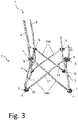
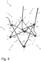
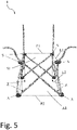
- the frame 2 comprises a plurality of pairs of rods 300.
- a pair of rods 300 is arranged on a front portion F of the chair 1 pre-arranged for user access, a pair of rods 300 is arranged on a rear portion P opposite to the front portion F, and additional pairs of rods 300 are arranged on side portions L of the chair 1.
- the rods 3 of each pair of rods 300 are geometrically identical to each other.
- each rod has a tubular shape, i.e., it has a hollow circular section.
- each rod 3 of each pair of rods 300 has a lower end portion 30, an upper end portion 31, and a central portion 32 arranged between the lower and upper end portions 30, 31 and connected thereto.
- each rod 3 extends mainly along a first direction D1.
- the central portion 32 extends rectilinearly along the first direction D1 between the lower and upper end portions 30, 31.
- each rod 3 extend respectively along a second direction D2 and a third direction D3 arranged transversely to the first direction D1.
- the second and third directions D2, D3 are transversal to the first direction D1 and are transversal between each other.
- the geometric shape of the rods 3 having the central portion 32 extending along the first direction D1 and the lower and upper end portions 30, 31 along the second and third directions D2, D3, allows to increase the stability of the chair 1 by increasing the stiffness of the frame 2.
- the above shape of the rods 3 is capable of reducing the bending strain of the rods 3 when the chair 1 is under a load, and thus of increasing the stiffness of the frame 2.
- each rod comprises connecting portions 33 configured to connect the central portion 32 to the lower and upper end portions 30, 31.
- each connecting portion 33 is a bend in the rod 3.
- the connecting portions 33 are arranged between the seat plane S1 and the standing plane A1. In other words, preferably, the connecting portions 33 are located below the seat plane S1.
- the rods 3 of each pair of rods 300 are free to mutually rotate one relative to the other about an axis of rotation R-R passing through the respective central portions 31.
- the axis of rotation R-R of each pair of rods 300 is oriented perpendicular to a plane containing the first directions of the rods 3 of the considered pair 300.
- the rods 3 of each pair 300 by mutually rotating one relative to the other, switch the frame 2 between the seat configuration and the transport configuration.
- the different pairs of rods 300 are connected to each other.
- the upper end portions 31 of rods 3 belonging to different pairs of rods 300 are mutually connected two by two at a plurality of seat-supporting points S lying on a same seat plane S1.
- the chair 1 comprises a plurality of joint elements 8 arranged at a respective seat point S.
- Each joint element 8 is connected to the upper ends 31 of two rods 3 belonging to different pairs of rods 300.
- the upper end portions 31 belonging to different pairs of rods 3 are connected two by two to a respective joint element 8 arranged at a respective seat point S.
- the upper end portions 31 belonging to different pairs of rods 300 are hinged to the respective joint element 8 so that they can rotate relative to the latter and thus also relative to each other.
- the upper end portions 31 rotate relative to the respective joint member 8 to switch the frame 2 between the seat and transport configuration.
- the different pairs of rods 300 are connected to each other at the lower end portions 30.
- the lower end portions 30 of rods 3 belonging to different pairs of rods 300 are mutually connected two by two at a plurality of footholds A lying on a same standing plane A1.
- the chair 1 comprises a plurality of standing feet 7 adapted to be arranged on a surface standing area on which the chair 1 stands.
- Each standing foot 7 is connected to the lower ends 30 of two rods 3 belonging to different pairs of rods 300.
- the lower portions 30 belonging to different pairs of rods 3 are connected two by two to a respective standing foot 7 arranged at a foothold A.
- the lower end portions 30 belonging to different pairs of rods 300 are hinged to the respective standing foot 7 so as to be able to rotate relative to the latter and thus to each other.
- the lower end portions 30 rotate relative to the respective standing foot 7 to switch the frame 2 between the seat and transport configuration.
- the plurality of seat-supporting points S are arranged such to define vertices of a first rectangular parallelogram P1 in the seat plane S1.
- the seat-supporting points S are four and, joining them two by two with first sides L1, defines the first rectangular parallelogram P1.
- the plurality of footholds A are arranged such to define the vertices of a second rectangular parallelogram P2 in the standing plane A1.
- the footholds are four and, by joining them two by two with second sides L2, a second rectangular parallelogram P2 is defined.
- the second sides L2 of the second parallelogram P2 extend along a length of at least 15% greater than the length of the respective first sides L1 of the first parallelogram.
- the first and second parallelograms PI, P2 are similar and the similarity ratio L 2 L 1 is greater than 1.15.
- the chair 1 preferably comprises a pair of pillars 4.
- Each pillar 4 is connected to a respective foothold A and to a respective seat-supporting point S located at the rear part P of the chair 1.
- each pillar 4 is therefore arranged in the part opposite to the front part F by means of which the user has access to the chair 1 for sitting.
- each pillar 4 extends along a direction substantially perpendicular to the standing plane A1 from the respective foothold A to beyond the respective seat-supporting point S.
- Each pillar 4 is therefore projecting from the seat plane S1 and preferably extends beyond the seat plane S1 by a length comparable to that of the user's trunk extension.
- the chair 1 object of the present invention comprises a backrest 5 adapted to support a user's back.
- the backrest 5 is made of textile material and is fixed to the pair of pillars 4 so as to define the back-supporting surface 5a as shown in Figure 1 .
- Such back-supporting surface 5a is arranged at the rear part P of the chair 1 and is substantially oriented transversally to the seat plane S1 when the frame 2 is in the seat configuration.
- the chair 1 comprises a seat 6 extending in the seat plane S and adapted to support a user.
- a seat 6 being made of textile material and being fixed to the frame 2 at the plurality of seat-supporting points S, as shown in Figure 1 .
Landscapes
- Special Chairs (AREA)
- Chair Legs, Seat Parts, And Backrests (AREA)
- Motorcycle And Bicycle Frame (AREA)
Applications Claiming Priority (1)
| Application Number | Priority Date | Filing Date | Title |
|---|---|---|---|
| IT102021000003983A IT202100003983A1 (it) | 2021-02-22 | 2021-02-22 | Sedia richiudibile |
Publications (1)
| Publication Number | Publication Date |
|---|---|
| EP4046535A1 true EP4046535A1 (fr) | 2022-08-24 |
Family
ID=75660278
Family Applications (1)
| Application Number | Title | Priority Date | Filing Date |
|---|---|---|---|
| EP22157473.4A Withdrawn EP4046535A1 (fr) | 2021-02-22 | 2022-02-18 | Chaise pliante |
Country Status (2)
| Country | Link |
|---|---|
| EP (1) | EP4046535A1 (fr) |
| IT (1) | IT202100003983A1 (fr) |
Citations (3)
| Publication number | Priority date | Publication date | Assignee | Title |
|---|---|---|---|---|
| US6179374B1 (en) * | 2000-04-18 | 2001-01-30 | Larry Tang | Collapsible reclining beach chair |
| US8303032B1 (en) * | 2011-03-16 | 2012-11-06 | Platta Bruce K | Portable collapsible chair and sling |
| WO2013029089A1 (fr) | 2011-08-26 | 2013-03-07 | Leisurelife (Aust) Pty Ltd | Ensemble siège pliant |
Family Cites Families (1)
| Publication number | Priority date | Publication date | Assignee | Title |
|---|---|---|---|---|
| US9596938B2 (en) * | 2015-04-08 | 2017-03-21 | Heb Grocery Company, Lp | Folding chair |
-
2021
- 2021-02-22 IT IT102021000003983A patent/IT202100003983A1/it unknown
-
2022
- 2022-02-18 EP EP22157473.4A patent/EP4046535A1/fr not_active Withdrawn
Patent Citations (4)
| Publication number | Priority date | Publication date | Assignee | Title |
|---|---|---|---|---|
| US6179374B1 (en) * | 2000-04-18 | 2001-01-30 | Larry Tang | Collapsible reclining beach chair |
| US8303032B1 (en) * | 2011-03-16 | 2012-11-06 | Platta Bruce K | Portable collapsible chair and sling |
| WO2013029089A1 (fr) | 2011-08-26 | 2013-03-07 | Leisurelife (Aust) Pty Ltd | Ensemble siège pliant |
| AU2012304252A1 (en) * | 2011-08-26 | 2014-04-17 | Leisurelife (Aust) Pty Ltd | Foldable chair assembly |
Also Published As
| Publication number | Publication date |
|---|---|
| IT202100003983A1 (it) | 2022-08-22 |
Similar Documents
| Publication | Publication Date | Title |
|---|---|---|
| US4919481A (en) | Multiple positionable chair construction | |
| US4290643A (en) | Folding chair | |
| KR930010033B1 (ko) | 의자 등받이 | |
| US12053099B2 (en) | Foldable rocking chair frame and chair having same | |
| US6776433B2 (en) | Assistive mobility device | |
| US3822422A (en) | Combination multiple purpose campers folding cot and portable pack frame | |
| US20130320651A1 (en) | Collapsible Chair With Collapsible Back Support | |
| US3309134A (en) | Interchangeable luggage-chair structure | |
| EP0539444A1 (fr) | Repose-pied. | |
| US5842741A (en) | Duroswing | |
| CA2801320A1 (fr) | Chaise pliable pourvue d'un support dorsal pliable | |
| US2738001A (en) | Reclining chair for invalids | |
| US20030062757A1 (en) | Multiuse portable chair | |
| US20160206101A1 (en) | Slimfold director chair with reclining backrest | |
| US20030168899A1 (en) | Folding portable foot station | |
| US5449220A (en) | Selectable height folding chair apparatus | |
| US4577878A (en) | Folding wheelchair | |
| EP4046535A1 (fr) | Chaise pliante | |
| EP0415893A1 (fr) | Fauteuil transatlantique transformable en un lit de bronzage | |
| US5058948A (en) | Foldable chair | |
| US10159349B1 (en) | Folding sofa | |
| US673100A (en) | Invalid's walking-chair. | |
| US6302037B1 (en) | Posture stabilizing demountable component table system | |
| KR20210050341A (ko) | 등받이 각도 조절기능을 갖는 접이식 릴렉스 체어 | |
| JP4923307B1 (ja) | 担架兼用長椅子 |
Legal Events
| Date | Code | Title | Description |
|---|---|---|---|
| PUAI | Public reference made under article 153(3) epc to a published international application that has entered the european phase |
Free format text: ORIGINAL CODE: 0009012 |
|
| STAA | Information on the status of an ep patent application or granted ep patent |
Free format text: STATUS: THE APPLICATION HAS BEEN PUBLISHED |
|
| AK | Designated contracting states |
Kind code of ref document: A1 Designated state(s): AL AT BE BG CH CY CZ DE DK EE ES FI FR GB GR HR HU IE IS IT LI LT LU LV MC MK MT NL NO PL PT RO RS SE SI SK SM TR |
|
| STAA | Information on the status of an ep patent application or granted ep patent |
Free format text: STATUS: REQUEST FOR EXAMINATION WAS MADE |
|
| 17P | Request for examination filed |
Effective date: 20230209 |
|
| RBV | Designated contracting states (corrected) |
Designated state(s): AL AT BE BG CH CY CZ DE DK EE ES FI FR GB GR HR HU IE IS IT LI LT LU LV MC MK MT NL NO PL PT RO RS SE SI SK SM TR |
|
| STAA | Information on the status of an ep patent application or granted ep patent |
Free format text: STATUS: EXAMINATION IS IN PROGRESS |
|
| 17Q | First examination report despatched |
Effective date: 20240115 |
|
| STAA | Information on the status of an ep patent application or granted ep patent |
Free format text: STATUS: THE APPLICATION IS DEEMED TO BE WITHDRAWN |
|
| 18D | Application deemed to be withdrawn |
Effective date: 20240516 |