EP4046570A1 - Système de détermination d'état de la marche, procédé de détermination d'état de la marche, et programme de détermination d'état de la marche - Google Patents
Système de détermination d'état de la marche, procédé de détermination d'état de la marche, et programme de détermination d'état de la marche Download PDFInfo
- Publication number
- EP4046570A1 EP4046570A1 EP21202119.0A EP21202119A EP4046570A1 EP 4046570 A1 EP4046570 A1 EP 4046570A1 EP 21202119 A EP21202119 A EP 21202119A EP 4046570 A1 EP4046570 A1 EP 4046570A1
- Authority
- EP
- European Patent Office
- Prior art keywords
- movement
- feature amount
- person
- gait state
- state determination
- Prior art date
- Legal status (The legal status is an assumption and is not a legal conclusion. Google has not performed a legal analysis and makes no representation as to the accuracy of the status listed.)
- Withdrawn
Links
Images


Classifications
-
- A—HUMAN NECESSITIES
- A61—MEDICAL OR VETERINARY SCIENCE; HYGIENE
- A61B—DIAGNOSIS; SURGERY; IDENTIFICATION
- A61B5/00—Measuring for diagnostic purposes; Identification of persons
- A61B5/103—Measuring devices for testing the shape, pattern, colour, size or movement of the body or parts thereof, for diagnostic purposes
- A61B5/11—Measuring movement of the entire body or parts thereof, e.g. head or hand tremor or mobility of a limb
- A61B5/112—Gait analysis
-
- A—HUMAN NECESSITIES
- A61—MEDICAL OR VETERINARY SCIENCE; HYGIENE
- A61B—DIAGNOSIS; SURGERY; IDENTIFICATION
- A61B5/00—Measuring for diagnostic purposes; Identification of persons
- A61B5/103—Measuring devices for testing the shape, pattern, colour, size or movement of the body or parts thereof, for diagnostic purposes
- A61B5/11—Measuring movement of the entire body or parts thereof, e.g. head or hand tremor or mobility of a limb
- A61B5/1121—Determining geometric values, e.g. centre of rotation or angular range of movement
- A61B5/1122—Determining geometric values, e.g. centre of rotation or angular range of movement of movement trajectories
-
- A—HUMAN NECESSITIES
- A61—MEDICAL OR VETERINARY SCIENCE; HYGIENE
- A61B—DIAGNOSIS; SURGERY; IDENTIFICATION
- A61B5/00—Measuring for diagnostic purposes; Identification of persons
- A61B5/40—Detecting, measuring or recording for evaluating the nervous system
- A61B5/4076—Diagnosing or monitoring particular conditions of the nervous system
- A61B5/4082—Diagnosing or monitoring movement diseases, e.g. Parkinson, Huntington or Tourette
-
- A—HUMAN NECESSITIES
- A61—MEDICAL OR VETERINARY SCIENCE; HYGIENE
- A61B—DIAGNOSIS; SURGERY; IDENTIFICATION
- A61B5/00—Measuring for diagnostic purposes; Identification of persons
- A61B5/48—Other medical applications
- A61B5/4842—Monitoring progression or stage of a disease
-
- A—HUMAN NECESSITIES
- A61—MEDICAL OR VETERINARY SCIENCE; HYGIENE
- A61B—DIAGNOSIS; SURGERY; IDENTIFICATION
- A61B5/00—Measuring for diagnostic purposes; Identification of persons
- A61B5/68—Arrangements of detecting, measuring or recording means, e.g. sensors, in relation to patient
- A61B5/6801—Arrangements of detecting, measuring or recording means, e.g. sensors, in relation to patient specially adapted to be attached to or worn on the body surface
- A61B5/6813—Specially adapted to be attached to a specific body part
- A61B5/6823—Trunk, e.g., chest, back, abdomen, hip
-
- A—HUMAN NECESSITIES
- A61—MEDICAL OR VETERINARY SCIENCE; HYGIENE
- A61B—DIAGNOSIS; SURGERY; IDENTIFICATION
- A61B5/00—Measuring for diagnostic purposes; Identification of persons
- A61B5/68—Arrangements of detecting, measuring or recording means, e.g. sensors, in relation to patient
- A61B5/6801—Arrangements of detecting, measuring or recording means, e.g. sensors, in relation to patient specially adapted to be attached to or worn on the body surface
- A61B5/6813—Specially adapted to be attached to a specific body part
- A61B5/6829—Foot or ankle
-
- A—HUMAN NECESSITIES
- A61—MEDICAL OR VETERINARY SCIENCE; HYGIENE
- A61B—DIAGNOSIS; SURGERY; IDENTIFICATION
- A61B5/00—Measuring for diagnostic purposes; Identification of persons
- A61B5/72—Signal processing specially adapted for physiological signals or for diagnostic purposes
- A61B5/7235—Details of waveform analysis
- A61B5/7246—Details of waveform analysis using correlation, e.g. template matching or determination of similarity
-
- A—HUMAN NECESSITIES
- A61—MEDICAL OR VETERINARY SCIENCE; HYGIENE
- A61B—DIAGNOSIS; SURGERY; IDENTIFICATION
- A61B5/00—Measuring for diagnostic purposes; Identification of persons
- A61B5/72—Signal processing specially adapted for physiological signals or for diagnostic purposes
- A61B5/7235—Details of waveform analysis
- A61B5/7264—Classification of physiological signals or data, e.g. using neural networks, statistical classifiers, expert systems or fuzzy systems
-
- A—HUMAN NECESSITIES
- A61—MEDICAL OR VETERINARY SCIENCE; HYGIENE
- A61B—DIAGNOSIS; SURGERY; IDENTIFICATION
- A61B5/00—Measuring for diagnostic purposes; Identification of persons
- A61B5/72—Signal processing specially adapted for physiological signals or for diagnostic purposes
- A61B5/7271—Specific aspects of physiological measurement analysis
- A61B5/7282—Event detection, e.g. detecting unique waveforms indicative of a medical condition
-
- A—HUMAN NECESSITIES
- A61—MEDICAL OR VETERINARY SCIENCE; HYGIENE
- A61B—DIAGNOSIS; SURGERY; IDENTIFICATION
- A61B5/00—Measuring for diagnostic purposes; Identification of persons
- A61B5/74—Details of notification to user or communication with user or patient; User input means
- A61B5/742—Details of notification to user or communication with user or patient; User input means using visual displays
Definitions
- a certain aspect of embodiments described herein relates to a gait state determination system, a gait state determination method, and a gait state determination program.
- Patent Document 1 discloses an art that measures the length of time for which both legs are in contact with the ground based on the output from sensors that measure the acceleration and the pressure applied to the human body to determine the deterioration in the locomotor function based on the ratio of the length of time for which both legs are in contact with the ground to the gait cycle.
- the present invention is made in view of those circumstances, and an objective thereof is to provide a gait state determination system, a gait state determination method, and a gait state determination program that can accurately make a determination regarding the gait state of a person in accordance with symptoms.
- a gait state determination system including: a sensor attached to a body of a person; and an information processing device configured to: acquire, using the sensor, data of a movement of at least a part of the body during a first period when the person is walking, identify a first feature amount of a first movement from the data acquired, and identify a second feature amount of a second movement from the data acquired, the first movement being determined in advance and corresponding to a symptom of the person, the second movement correlating with the first movement, make a determination regarding a gait state of the person based on the first feature amount of the first movement and the second feature amount of the second movement, and output a result of the determination.
- FIG. 1 schematically illustrates a configuration of an information processing system 100 in accordance with an embodiment.
- the information processing system 100 includes a sensing device 50, a physical therapist terminal 60, a doctor terminal 70, and a server 10 as an information processing device.
- the server 10, the physical therapist terminal 60, and the doctor terminal 70 are connected to a network 80 such as the Internet.
- the sensing device 50 includes sensors (an angular velocity sensor and an acceleration sensor), a control unit that controls the detection by the sensors, and a memory that stores detection results of the sensors.
- the sensing devices 50 are attached to both ankles and the waist of a patient when the patient conducts a gait test, which is one of the motor function tests, under the direction of a physical therapist, and detect temporal variations in angular velocity and acceleration.
- the sensing device 50 also includes an input button for inputting the start of the measurement and the end of the measurement.
- FIG. 2A and FIG. 2B illustrate types of data acquired from the sensing devices 50 attached to legs and a waist.
- FIG. 2A illustrates types of data acquired from the angular velocity sensor
- FIG. 2B illustrates types of data acquired from the acceleration sensor.
- data on anterior-posterior rotation (waistGyroX), data on vertical rotation (waistGyroY), and data on horizontal rotation (waistGyroZ) are acquired from the angular velocity sensor attached to the waist.
- data on anterior-posterior rotation (legGyroX), data on vertical rotation (legGyroY), and data on horizontal rotation (legGyroZ) are acquired from the angular velocity sensor attached to the ankle.
- data on horizontal acceleration (waistAccX), data on anterior-posterior acceleration (waistAccY), and data on vertical acceleration (waistAccZ) are acquired from the acceleration sensor attached to the waist.
- data on horizontal acceleration (legAccX), data on anterior-posterior acceleration (legAccY), and data on vertical acceleration (legAccZ) are acquired from the acceleration sensor attached to the ankle.
- FIG. 3 illustrates, as an example, time-series data of the horizontal rotation (waistGyroZ) acquired from the angular velocity sensor attached to the waist and time-series data of the horizontal rotation (legGyroZ) acquired from each of the angular velocity sensors attached to the ankles.
- the physical therapist terminal 60 is a terminal such as a personal computer (PC) or a tablet terminal used by the physical therapist.
- the physical therapist terminal 60 acquires detection results (time-series data of angular velocities and accelerations) of the sensing devices 50 by connecting to the sensing devices 50. Additionally, the physical therapist terminal 60 transmits the acquired time-series data of the angular velocities and the accelerations to the server 10 through the network 80.
- detection results time-series data of angular velocities and accelerations
- FIG. 4A illustrates a hardware configuration of the physical therapist terminal 60.
- the physical therapist terminal 60 includes a central processing unit (CPU) 190, a read only memory (ROM) 192, a random access memory (RAM) 194, a storage unit (e.g., a solid state drive (SSD) or a hard disk drive (HDD)) 196, a network interface 197, a display unit 193, an input unit 195, and a portable storage medium drive 199.
- the display unit 193 includes a liquid crystal display or the like
- the input unit 195 includes a keyboard, a mouse, a touch panel, or any combination of them.
- the portable storage medium drive 199 is a device that can read data stored in a portable storage medium 191. These components of the physical therapist terminal 60 are coupled to a bus 198.
- the physical therapist terminal 60 also includes a communication unit that communicates with the sensing devices 50 wirelessly or by wire.
- the doctor terminal 70 is a terminal such as a PC or the like used by a doctor.
- the doctor terminal 70 displays information transmitted from the server 10 to present the information to the doctor, and has the same hardware configuration as the physical therapist terminal 60 as illustrated in FIG. 4A .
- the doctor refers to the information displayed on the doctor terminal 70 to check symptoms of the patient, consider a course of treatment, and check medication effectiveness.
- the server 10 analyzes the movement corresponding to the symptom of the patient based on the time-series data of the angular velocities and the accelerations acquired from the physical therapist terminal 60.
- the server 10 make a determination regarding the gait state of the patient, and outputs a screen presenting the determination result to the doctor terminal 70. More specifically, the server 10 calculates the feature amount of a first movement (a compensating movement) corresponding to the symptom (the disease name) of the patient and the feature amount of a second movement (a compensated movement) correlating with the compensating movement, based on the time-series data of the angular velocities and the accelerations. Then, the server 10 makes a determination regarding the gait state of the patient based on the calculated feature amounts.
- the compensating movement means a movement in which another part of the body achieves the aimed motion instead of the diseased part to assist the insufficiency of the aimed motion.
- Examples of the compensating movement include, but are not limited to, starting to walk using the body trunk without bending the legs and walking with a pigeon-toe gait.
- the compensated movement means another movement that correlates with the compensating movement and appears immediately before or immediately after the compensating movement. Examples of the compensated movement include, but are not limited to, causing the heel to come in contact with the ground, lifting the toe from the ground, and moving the waist.
- FIG. 4B illustrates a hardware configuration of the server 10.
- the server 10 includes a CPU 90, a ROM 92, a RAM 94, a storage unit (an SSD or an HDD) 96, a network interface 97, and a portable storage medium drive 99. These components of the server 10 are coupled to a bus 98.
- the functions of each unit illustrated in FIG. 5 are implemented by the CPU 90 executing programs (including a gait state determination program) stored in the ROM 92 or the storage unit 96, or programs read by the portable storage medium drive 99 from the portable storage medium 91.
- the functions of each unit in FIG. 5 may be implemented by an integrated circuit such as, but not limited to, an application specific integrated circuit (ASIC) or a field programmable gate array (FPGA).
- ASIC application specific integrated circuit
- FPGA field programmable gate array
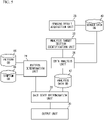
- FIG. 5 is a functional block diagram of the server 10.
- execution of the programs by the CPU 90 implements the functions as a sensing result acquisition unit 20, an analysis target section identification unit 22, a data analysis unit 24, a pattern determination unit 26, a gait state determination unit 28, and an output unit 30.
- the sensing result acquisition unit 20 acquires data detected by the sensing devices 50 during the gait test of the patient, and stores the acquired data in a sensor data database (DB) 40.
- the sensor data DB 40 has a data structure illustrated in FIG. 6 , as an example.
- the sensor data DB 40 stores data acquired in the angular velocity sensors and the acceleration sensors at each time (UTC) as illustrated in FIG. 6 .
- FIG. 3 is obtained by illustrating data (GyroZ) indicating the horizontal rotations acquired from the acceleration sensors attached to the waist and both ankles graphically among data presented in FIG. 6 .
- the analysis target section identification unit 22 extracts gait events (feature points) from the time-series data acquired through one gait test.
- the analysis target section identification unit 22 uses the data (e.g., the time-series data of the horizontal rotations (legGyroZ)) acquired from both ankles in FIG. 3 when extracting the gait events.
- FIG. 7A is an enlarged view of part (an area H) of the time-series data of the left leg and the right leg illustrated in FIG. 3 .
- FIG. 7B presents a list of the gait events (the feature points).
- the analysis target section identification unit 22 analyzes the data illustrated in FIG. 7A to identify the gait events (the feature points) from the time-series data.
- the analysis target sections include sections illustrated in FIG. 7C .
- the stride section is defined as the section between the toe off point of one leg and the toe off point of another leg. Thus, the section indicated by (1) in FIG. 7A is identified as the stride section.
- the swing section is defined as the section between the toe off point of one leg and the heel contact point of the same leg.
- the section indicated by (2) in FIG. 7A is identified as the swing section.
- each gait section is identified.
- the numbers in parentheses in FIG. 7A correspond to the numbers in parentheses in FIG. 7C .
- the data analysis unit 24 analyzes the time-series data using the analysis target sections identified by the analysis target section identification unit 22 to acquire information on gate and feature amounts, and stores them in an analysis data DB 42.
- the analysis data DB 42 has a data structure illustrated in FIG. 8 .
- the analysis data DB 42 stores the "information on gate” and the "feature amount” in association with the time (UTC) when the gait test is started.
- the information on gait includes information such as the "gate initiation time”, the "gait finish time”, the "gait time length (s)", the “average of stride time length (s)", the “average step length (cm)", the “average gate speed (cm/s)", and the "number of steps".
- the feature amounts include various statistics values of the data of each sensor in each of the analysis target sections.
- the feature amount in FIG. 8 is described in the form of "sensor data analysis target section_statistics value" that indicates the sensor data, the analysis target section, and the statistics value in this order.
- the sensor data includes 12 types of data as illustrated in FIG. 9A
- the analysis target sections include 11 types of analysis target sections as illustrated in FIG. 9B .
- the statistics values include 9 types of statistics values as illustrated in FIG. 10 .
- the equation of each statistics value in FIG. 10 is the equation when the sensor signal X(i) (i ⁇ [Ns, Ne]) is acquired where N s represents the starting point and Ne represents the ending point.
- the mean value of data in the swing section is described as "waistGyroX_swingAll_meanNorm".
- the mean value of data in the swing section is described as "waistGyroX_swingAll_meanNorm”.
- the pattern determination unit 26 determines the pattern of the combination of the compensating movement and the compensated movement according to the symptom of the patient.
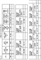
- the pattern determination unit 26 refers to a pattern DB 44 ( FIG. 11A and 11B ) and a symptom DB 46 ( FIG. 12 ).
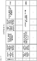
- the pattern DB 44 stores information on the combination of the compensating movement and the compensated movement. More specifically, the pattern DB 44 stores the "content of compensating movement", the "section where compensating movement appears”, the “feature amount representing compensating movement", the "target body part of compensated movement”, the “section where compensated movement appears”, the “feature amount used as compensated movement", and the "stage” in association with the item number as illustrated in FIG. 11A and FIG. 11B .
- the “content of compensating movement” indicates the specific content of the compensating movement
- the “section where compensating movement appears” indicates in which of 11 analysis target sections the compensating movement appears.
- the “feature amount representing compensating movement” indicates which of the feature amounts presented in FIG. 8 is to be used as the feature amount of the compensating movement.
- the "target body part of compensated movement” indicates the part of the body where the compensated movement appears, and the “section where compensated movement appears” indicates the analysis target section where the compensated movement appears.
- the “feature amount used as compensated movement” indicates which of the feature amounts presented in FIG. 8 is to be used as the feature amount of the compensated movement.
- “Common" or "severe" is described in the "stage".
- a pattern described as "common” means a pattern used to determine the presence or absence of a symptom
- a pattern described as “severe” means a pattern used to determine whether the symptom is severe.
- the "section where compensating movement appears” is an example of a second period during which the first movement is performed.
- the "feature amount representing compensating movement” is an example of a third feature amount indicating the first movement.
- the "section where compensated movement appears” is an example of a third period during which the second movement is performed.
- the “feature amount used as compensated movement” is an example of a fourth feature amount indicating the second movement.
- the symptom DB 46 stores the symptom and the item number of the pattern DB 44 in association with each other as illustrated in FIG. 12 .
- the pattern determination unit 26 refers to the symptom DB 46, identifies the item numbers (1 to 5) corresponding to muscular dystrophy, and sets the patterns corresponding to the identified item numbers (1 to 5) in the pattern DB 44 illustrated in FIG. 11A and FIG. 11B as the patterns used for the process.
- the gait state determination unit 28 acquires the feature amount of the compensating movement and the feature amount of the compensated movement with respect to each of the patterns set by the pattern determination unit 26, and calculates the compensation change using the acquired feature amounts.
- the gait state determination unit 28 also determines the gait state of the patient, i.e., the presence or absence of the symptom and the severity based on the calculated compensation change.
- the output unit 30 acquires the result determined by the gait state determination unit 28, generates an output screen, and outputs the output screen to the doctor terminal 70.
- the doctor terminal 70 acquires the output screen, and displays the output screen on the display unit 193.
- FIG. 13 is a flowchart illustrating the pre-process executed by the sensing device 50.
- the sensing device 50 acquires the time-series data of the angular velocity and the acceleration during the period when the patient is conducting the gait test under the direction of the physical therapist.
- the patient wears the sensing devices 50 on both ankles and the waist, and is ready for the gait test.
- the gait test is conducted for a distance of, for example, 10 m, and the sensing devices 50 detect the angular velocities and the accelerations of both ankles and the waist while the patient is walking straight for a distance of 10 m.
- step S10 the control unit of the sensing device 50 waits until an instruction to start measurement is input. For example, when an input button, which is provided to the sensing device 50 and is used to input the start of the measurement, is pressed by a physical therapist, the control unit proceeds to step S12.
- step S12 the control unit waits until a predetermined time elapses.
- the predetermined time here means the measurement interval, and is about several milliseconds to several tens of milliseconds.
- control unit detects the angular velocities and the accelerations using the angular velocity sensors and the acceleration sensors, and stores them in the memory together with time information.
- step S16 the control unit determines whether the measurement is finished. For example, when the input button for inputting the end of measurement is pressed by the physical therapist, the determination in step S16 becomes YES. By contrast, when the input button is not pressed, the process returns to step S12. Thereafter, until the determination in step S16 becomes YES, the control unit repeats the processes and the determinations in steps S12 to S16. When the determination in step S16 becomes YES, the process proceeds to step S18, and the control unit transmits the data stored in the memory to the physical therapist terminal 60 and ends the entire process of FIG. 13 . The physical therapist relates the data to the patient in the physical therapist terminal 60, and then transmits the data to the server 10.
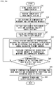
- the process of FIG. 14 is a process started when the time-series data of the angular velocity and the acceleration of a certain patient (a subject patient) is transmitted from the physical therapist terminal 60, as an example.
- step S30 the sensing result acquisition unit 20 acquires the time-series data (the sensor data) of the angular velocities and the accelerations of the subject patient, and stores them in the sensor data DB 40.
- the sensing result acquisition unit 20 acquires the data such as the data illustrated in FIG. 3 , and stores the acquired data in the sensor data DB 40 illustrated in FIG. 6 .
- step S32 the analysis target section identification unit 22 acquires the data stored in the sensor data DB 40.
- the analysis target section identification unit 22 acquires the symptom of the subject patient from an electronic health record server or the like, and identifies the item number of the pattern corresponding to the symptom of the subject patient based on the symptom DB 46 of FIG. 12 .
- the analysis target section identification unit 22 refers to the pattern DB 44 illustrated in FIG. 11A and FIG. 11B , extracts the pattern of the compensating movement and the compensated movement corresponding to the identified item number. For example, when the symptom of the subject patient is muscular dystrophy, the patterns of the item numbers 1 to 5 are set as the patterns to be used, based on FIG. 12 .
- step S36 the analysis target section identification unit 22 extracts the gait events (the feature points) from the sensor data and determines the analysis target sections.
- the analysis target section identification unit 22 extracts the gait event for each step of the patient as illustrated in FIG. 7A , and determines the analysis target sections for each step of the patient.
- step S38 the data analysis unit 24 calculates the information on gait and the feature amounts to be stored in the analysis data DB 42 illustrated in FIG. 8 .
- the information on gait is information such as the gait time length, the average of the stride time length, and the like presented in FIG. 8
- the feature amounts are 1188 types of feature amounts such as "legGyroX_swingAll_meanNorm".
- the gait state determination unit 28 extracts the feature amount D(Xm) of the compensating movement and the feature amount D(Ym) of the compensated movement corresponding to one (for example, a pattern m) of the patterns that have been set, among the calculated feature amounts. For example, in the case of the pattern of the item number 1 in the pattern DB 44 illustrated in FIG. 11A , the gait state determination unit 28 extracts the value (56.121) of "legGyroZ_swingAllmeanNorm" as the feature amount D(Xm). The gait state determination unit 28 also extracts the value (52.1006) of "waistGyroY_doublesupportAll_maxAbs" as the feature amount D(Ym).
- step S42 the gait state determination unit 28 calculates the compensation change ⁇ Dm from the following equation (1) using the feature amount D(Xm) of the compensating movement and the feature amount D(Ym) of the compensated movement.
- ⁇ Dm D Xm / D Ym
- step S44 the gait state determination unit 28 determines whether the compensation changes of all the patterns that have been set have been calculated.
- the determination in step S44 is NO, the process returns to step S40, and the process of extracting the feature amounts of the compensating movement and the compensated movement (S40) and the process of calculating the compensation change (S42) are repeated.
- the determination in step S44 becomes YES, the process proceeds to step S46.
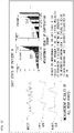
- the gait state determination unit 28 refers to the compensation changes of the patterns that have been set and the determination condition to determine the state of the patient. For example, discussed is a case where the compensation changes of healthy people and the compensation changes of patients with diseases are distributed as illustrated in FIG. 15 as a result of the examination conducted in advance in the case of the pattern of the item number 2 in the pattern DB 44 illustrated in FIG. 11A .
- the distribution presented in FIG. 15 reveals that the boundary between the healthy people and the patients with diseases is at a compensation change of ⁇ 0.025. Therefore, the gait state determination unit 28 determines that the patient experiences the symptom when the compensation change is 0.025 or greater for the pattern of the item number 2.
- the gait state determination unit 28 checks whether the compensation changes are included within the respective ranges determined with respect to the patterns of which the stages are "common" in the pattern DB 44 illustrated in FIG. 11A and FIG. 11B , and determines that the patient experiences the symptom when any of the compensation changes is included in the corresponding range.
- the gait state determination unit 28 determines that the severity is 33.3%.
- step S48 the output unit 30 generates a screen based on the determination result of step S46, and outputs the generated screen to the doctor terminal 70.
- the screen generated by the output unit 30 is, for example, a screen illustrated in FIG. 16 .
- the screen illustrated in FIG. 16 displays the measurement results of the sensors of the ankles and the waist (the measurement results of all body parts), the measurement result of the compensation change, and textual information indicating the presence or absence of the symptom and the severity.
- the output unit 30 collects necessary data from FIG. 6 based on the UTC of the data (the data in the analysis data DB 42 ( FIG. 8 )) that have been used for analysis, the gate initiation time, and the gait finish time when displaying the measurement results of all body parts.
- the UTC of the data the data in the analysis data DB 42 ( FIG. 8 )
- the measurement results of the angular velocity sensors or the acceleration sensors in one direction are presented in the space for the measurement results of all body parts.
- the output unit 30 may generate a screen that can display the measurement results of the angular velocity sensors or the acceleration sensors in the directions selected by the doctor according to the selection by the doctor.
- step S30 achieves the process of acquiring the data of the movement of at least a part of the body during the period when the patient is walking, using the sensing device 50 attached to the body of the patient.
- Steps S34, S36, S38, and S40 achieve the process of identifying a first feature amount of a predetermined first movement (the compensating movement) corresponding to the symptom of the patient and a second feature amount of a second movement (the compensated movement) correlating with the first movement (the compensating movement), from the data acquired from the sensing device 50.
- steps S42, S46, and S48 achieve the process of making a determination regarding the gait state of the patient based on the feature amount of the first movement (the compensating movement) and the feature amount of the second movement (the compensated movement) and outputting the determination result.
- the server 10 acquires the time-series data of the angular velocities and the accelerations of the ankles and the waist during the period when the patient conducts the gait test, which are detected using the sensing devices 50 attached to the body of the patient.
- the server 10 identifies the feature amount of the predetermined compensating movement corresponding to the symptom of the patient and the feature amount of the compensated movement correlating with the compensating movement from the detected time-series data. Then, the server 10 determines the presence or absence of the symptom of the patient and the severity based on the ratio of the feature amount of the compensating movement and the feature amount of the compensated movement (the compensation change), and outputs the determination result.
- the present embodiment allows the present embodiment to determine the presence or absence of the symptom and the severity accurately because the present embodiment quantifies the characteristic movements that appear in gait for each disease, and determines the presence or absence of the symptom and the severity based on the value. Therefore, the doctor can check the symptom of the patient, consider a course of treatment, and check medication effectiveness by referring to the information displayed on the doctor terminal 70. In this case, by performing a determination using the compensation change of the pattern selected according to the symptom, more precise determination of the symptom can be made than in the case using the conventional classification of disability stages (see https://www.neurology-jp.org/guidelinem/pdf/dmd_03.pdf, for example).
- the feature amount of the compensating movement and the feature amount of the compensated movement are what kind of statistics value detected by which sensor during which analysis target section. This allows the gait state determination unit 28 to easily identify the feature amount of the compensating movement and the feature amount of the compensated movement.
- the gait state determination unit 28 determines the presence or absence of the symptom based on whether the ratio of the feature amount of the compensating movement and the feature amount of the compensated movement (the compensation change) is included in a predetermined range. This allows the presence or absence of the symptom to be accurately determined based on the feature amount of the compensating movement and the feature amount of the compensated movement determined with respect to each symptom.
- the patient wears the sensing devices 50 on the ankles and the waist when conducting the gait test. This prevents muscles and thick blood vessels from being compressed unlike in the case where the sensing device 50 is attached to the thigh. This reduces the physical load on the patient.
- the above embodiment describes a case where the data analysis unit 24 calculates all 1188 feature amounts in step S38 of FIG. 14 , but does not intend to suggest any limitation.
- the data analysis unit 24 calculates only the feature amounts included in the patterns that are determined, by the pattern determination unit 26, to be used, and store the calculated feature amounts in the analysis data DB 42.
- a plurality of threshold values may be set for each pattern to divide the compensation change into ranges such as "normal”, “mild”, and “severe”, and the severity of the patient may be determined based on which range the compensation change of the patient falls within. For example, when the compensation change is calculated for N patterns for one patient, it is checked and counted which of "normal”, “mild”, and “severe” each compensation change indicates. Then, the severity that are most counted may be determined as the severity of the patient among "normal", “mild”, and “severe”. Alternatively, each pattern may be weighed, and the severity of the patient may be determined taking into account the weight.
- the pattern in which the target body part of the compensating movement is different from the target body part of the compensated movement does not intend to suggest any limitation.
- the target body part of the compensating movement may be the same as the target body part of the compensated movement.
- the above embodiment describes a case where the movement correlating with the compensating movement is the compensated movement before or after the compensating movement, but does not intend to suggest any limitation.
- the movement correlating with the compensating movement may not be necessarily the compensated movement.
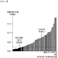
- the feature amount relating to gait such as the "average gait speed for one measurement" may be used. Discussed is a case where in the pre-examination, the compensation changes of healthy people and the compensation changes of patients with diseases are distributed as illustrated in FIG. 18 in this case. From the distribution illustrated in FIG. 18 , it is considerable that the boundary between the patients with diseases and the healthy people is at a compensation change of ⁇ 0.025. Therefore, the gait state determination unit 28 determines that the patient experiences the symptom when the compensation change is 0.025 or less for the pattern of the item number n.
- the above embodiment determines the gait state (the presence or absence of symptoms and the severity) of the patient based on the compensation change acquired from the ratio of the feature amount of the compensating movement and the feature amount of the compensated movement (see the equation (1)), but does not intend to suggest any limitation.
- the value acquired from the feature amount of the compensation change and the feature amount of the compensated movement may be defined as the compensation change, and the gait state of the patient may be determined based on this value.
- the above embodiment describes a case where the sensing device 50 includes both the angular velocity sensor and the acceleration sensor, but does not intend to suggest any limitation.
- the sensing device 50 may include only one of the angular velocity sensor and the acceleration sensor.
- the above embodiment describes a case where the process of FIG. 14 is executed by the server 10, but does not intend to suggest any limitation.
- part of or the entire of the process in FIG. 14 may be executed by the physical therapist terminal 60 or the doctor terminal 70. That is, the process of FIG. 14 is achieved by one or more devices in the information processing system 100.
- the above embodiment describes a case where the sensing devices 50 are connected to the physical therapist terminal 60, but does not intend to suggest any limitation.
- the sensing device 50 may be connected to the doctor terminal 70.
- the doctor terminal 70 executes the same process as the physical therapist terminal 60 in the above embodiment.
- the above embodiment describes a case where the output unit 30 outputs the feature amounts to the doctor terminal 70, but does not intend to suggest any limitation.
- the output unit 30 may output the feature amounts to other terminals.
- the output unit 30 may output the feature amounts to the physical therapist terminal 60 or the terminal of a pharmaceutical company conducting trials.
- the above-described processing functions are implemented by a computer.
- a program in which processing details of the functions that a processing device (CPU) is to have are written is provided.
- the aforementioned processing functions are implemented by the computer executing the program.
- the program in which the processing details are written can be stored in a computer-readable storage medium (however, excluding carrier waves).
- the program When the program is distributed, it may be sold in the form of a portable storage medium such as a digital versatile disc (DVD) or a compact disc read only memory (CD-ROM) storing the program.
- DVD digital versatile disc
- CD-ROM compact disc read only memory
- the program may be stored in a storage device of a server computer, and the program may be transferred from the server computer to another computer over a network.
- a computer executing the program stores the program stored in a portable storage medium or transferred from a server computer in its own storage device.
- the computer then reads the program from its own storage device, and executes a process according to the program.
- the computer may directly read the program from a portable storage medium, and execute a process according to the program.
- the computer may successively execute a process, every time the program is transferred from a server computer, according to the received program.
Landscapes
- Health & Medical Sciences (AREA)
- Life Sciences & Earth Sciences (AREA)
- Engineering & Computer Science (AREA)
- Physics & Mathematics (AREA)
- Animal Behavior & Ethology (AREA)
- Veterinary Medicine (AREA)
- Biophysics (AREA)
- Pathology (AREA)
- Public Health (AREA)
- Biomedical Technology (AREA)
- Heart & Thoracic Surgery (AREA)
- Medical Informatics (AREA)
- Molecular Biology (AREA)
- Surgery (AREA)
- General Health & Medical Sciences (AREA)
- Physiology (AREA)
- Artificial Intelligence (AREA)
- Neurology (AREA)
- Computer Vision & Pattern Recognition (AREA)
- Psychiatry (AREA)
- Signal Processing (AREA)
- Dentistry (AREA)
- Oral & Maxillofacial Surgery (AREA)
- Neurosurgery (AREA)
- Geometry (AREA)
- Mathematical Physics (AREA)
- Developmental Disabilities (AREA)
- Fuzzy Systems (AREA)
- Evolutionary Computation (AREA)
- Measurement Of The Respiration, Hearing Ability, Form, And Blood Characteristics Of Living Organisms (AREA)
Applications Claiming Priority (1)
| Application Number | Priority Date | Filing Date | Title |
|---|---|---|---|
| JP2021002381A JP2022107432A (ja) | 2021-01-08 | 2021-01-08 | 歩行状態判定システム、歩行状態判定方法及び歩行状態判定プログラム |
Publications (1)
| Publication Number | Publication Date |
|---|---|
| EP4046570A1 true EP4046570A1 (fr) | 2022-08-24 |
Family
ID=78087277
Family Applications (1)
| Application Number | Title | Priority Date | Filing Date |
|---|---|---|---|
| EP21202119.0A Withdrawn EP4046570A1 (fr) | 2021-01-08 | 2021-10-12 | Système de détermination d'état de la marche, procédé de détermination d'état de la marche, et programme de détermination d'état de la marche |
Country Status (2)
| Country | Link |
|---|---|
| EP (1) | EP4046570A1 (fr) |
| JP (1) | JP2022107432A (fr) |
Citations (5)
| Publication number | Priority date | Publication date | Assignee | Title |
|---|---|---|---|---|
| JP2011177278A (ja) * | 2010-02-26 | 2011-09-15 | Tokyo Institute Of Technology | 歩行障害自動分析システム |
| JP2012179114A (ja) | 2011-02-28 | 2012-09-20 | Hiroshima Univ | 測定装置、測定方法、及び、測定プログラム |
| WO2017065241A1 (fr) * | 2015-10-14 | 2017-04-20 | 国立大学法人東京工業大学 | Dispositif de diagnostic automatisé |
| US20200138358A1 (en) * | 2018-11-02 | 2020-05-07 | National Cheng Kung University | Alzheimer's disease symptom evaluation system |
| US10842415B1 (en) * | 2019-10-25 | 2020-11-24 | Plethy, Inc. | Devices, systems, and methods for monitoring and assessing gait, stability, and/or balance of a user |
-
2021
- 2021-01-08 JP JP2021002381A patent/JP2022107432A/ja active Pending
- 2021-10-12 EP EP21202119.0A patent/EP4046570A1/fr not_active Withdrawn
Patent Citations (5)
| Publication number | Priority date | Publication date | Assignee | Title |
|---|---|---|---|---|
| JP2011177278A (ja) * | 2010-02-26 | 2011-09-15 | Tokyo Institute Of Technology | 歩行障害自動分析システム |
| JP2012179114A (ja) | 2011-02-28 | 2012-09-20 | Hiroshima Univ | 測定装置、測定方法、及び、測定プログラム |
| WO2017065241A1 (fr) * | 2015-10-14 | 2017-04-20 | 国立大学法人東京工業大学 | Dispositif de diagnostic automatisé |
| US20200138358A1 (en) * | 2018-11-02 | 2020-05-07 | National Cheng Kung University | Alzheimer's disease symptom evaluation system |
| US10842415B1 (en) * | 2019-10-25 | 2020-11-24 | Plethy, Inc. | Devices, systems, and methods for monitoring and assessing gait, stability, and/or balance of a user |
Also Published As
| Publication number | Publication date |
|---|---|
| JP2022107432A (ja) | 2022-07-21 |
Similar Documents
| Publication | Publication Date | Title |
|---|---|---|
| Chen et al. | Bring gait lab to everyday life: Gait analysis in terms of activities of daily living | |
| Witchel et al. | Thigh-derived inertial sensor metrics to assess the sit-to-stand and stand-to-sit transitions in the timed up and go (TUG) task for quantifying mobility impairment in multiple sclerosis | |
| Oh et al. | Validity of the Microsoft Kinect™ in assessing spatiotemporal and lower extremity kinematics during stair ascent and descent in healthy young individuals | |
| Atallah et al. | Observing recovery from knee-replacement surgery by using wearable sensors | |
| TW201403535A (zh) | 步態分析方法及步態分析系統 | |
| US20220338759A1 (en) | Device for calculating, during one step or each successive step of the gait of a subject, the push-off p0 of the subject | |
| JP2008504080A (ja) | バランス特性を測定するための力評価装置及び力評価方法 | |
| Scarton et al. | Comparison of lower limb muscle strength between diabetic neuropathic and healthy subjects using OpenSim | |
| US20230298760A1 (en) | Systems, devices, and methods for determining movement variability, illness and injury prediction and recovery readiness | |
| Sun et al. | Preliminary evaluation of a self-guided fall risk assessment tool for older adults | |
| Bohlke et al. | Accelerometry applications and methods to assess standing balance in older adults and mobility-limited patient populations: a narrative review | |
| US20200390389A1 (en) | Method and system for motor function rehabilitation and monitoring a patient's recovery | |
| US20240127958A1 (en) | Method for disease risk assessment | |
| TWI796275B (zh) | 疾病風險評估方法 | |
| JP6738250B2 (ja) | 歩行分析方法及び歩行分析装置 | |
| Igarashi et al. | Accelerometer-based gait characteristics and their discrimination of gait independence in inpatients with subacute stroke | |
| EP4046570A1 (fr) | Système de détermination d'état de la marche, procédé de détermination d'état de la marche, et programme de détermination d'état de la marche | |
| Junior et al. | Use of wearable inertial sensors for the assessment of spatiotemporal gait variables in children: A systematic review | |
| EP4331483B1 (fr) | Dispositif d'estimation d'émotion, système d'estimation d'émotion et procédé d'estimation d'émotion | |
| US20240203228A1 (en) | System and method for predicting a fall | |
| Papa et al. | Reproducibility and responsiveness of gait initiation in Parkinson’s disease | |
| JP7748108B2 (ja) | 運動支援装置、運動支援方法、運動支援システム及びプログラム | |
| JP7789254B1 (ja) | 膝関節置換術要否判定システム、膝関節置換術要否判定方法及び膝関節置換術要否判定プログラム | |
| US20250069755A1 (en) | Method of estimating health score and method of estimating changes in positions of parts of upper body | |
| EP3915473B1 (fr) | Programme de traitement d'informations, procédé de traitement d'informations et système de traitement d'informations |
Legal Events
| Date | Code | Title | Description |
|---|---|---|---|
| PUAI | Public reference made under article 153(3) epc to a published international application that has entered the european phase |
Free format text: ORIGINAL CODE: 0009012 |
|
| STAA | Information on the status of an ep patent application or granted ep patent |
Free format text: STATUS: THE APPLICATION HAS BEEN PUBLISHED |
|
| AK | Designated contracting states |
Kind code of ref document: A1 Designated state(s): AL AT BE BG CH CY CZ DE DK EE ES FI FR GB GR HR HU IE IS IT LI LT LU LV MC MK MT NL NO PL PT RO RS SE SI SK SM TR |
|
| STAA | Information on the status of an ep patent application or granted ep patent |
Free format text: STATUS: REQUEST FOR EXAMINATION WAS MADE |
|
| 17P | Request for examination filed |
Effective date: 20221227 |
|
| RBV | Designated contracting states (corrected) |
Designated state(s): AL AT BE BG CH CY CZ DE DK EE ES FI FR GB GR HR HU IE IS IT LI LT LU LV MC MK MT NL NO PL PT RO RS SE SI SK SM TR |
|
| STAA | Information on the status of an ep patent application or granted ep patent |
Free format text: STATUS: EXAMINATION IS IN PROGRESS |
|
| 17Q | First examination report despatched |
Effective date: 20230208 |
|
| STAA | Information on the status of an ep patent application or granted ep patent |
Free format text: STATUS: THE APPLICATION HAS BEEN WITHDRAWN |
|
| 18W | Application withdrawn |
Effective date: 20231031 |