EP4046573A1 - Elektrodensystem zur mehrfachen erfassung elektrokardiographischer ableitungen - Google Patents
Elektrodensystem zur mehrfachen erfassung elektrokardiographischer ableitungen Download PDFInfo
- Publication number
- EP4046573A1 EP4046573A1 EP22154296.2A EP22154296A EP4046573A1 EP 4046573 A1 EP4046573 A1 EP 4046573A1 EP 22154296 A EP22154296 A EP 22154296A EP 4046573 A1 EP4046573 A1 EP 4046573A1
- Authority
- EP
- European Patent Office
- Prior art keywords
- electrode
- electrodes
- supports
- electrode system
- connector
- Prior art date
- Legal status (The legal status is an assumption and is not a legal conclusion. Google has not performed a legal analysis and makes no representation as to the accuracy of the status listed.)
- Granted
Links
Images


Classifications
-
- A—HUMAN NECESSITIES
- A61—MEDICAL OR VETERINARY SCIENCE; HYGIENE
- A61B—DIAGNOSIS; SURGERY; IDENTIFICATION
- A61B5/00—Measuring for diagnostic purposes; Identification of persons
- A61B5/24—Detecting, measuring or recording bioelectric or biomagnetic signals of the body or parts thereof
- A61B5/25—Bioelectric electrodes therefor
- A61B5/251—Means for maintaining electrode contact with the body
- A61B5/257—Means for maintaining electrode contact with the body using adhesive means, e.g. adhesive pads or tapes
-
- A—HUMAN NECESSITIES
- A61—MEDICAL OR VETERINARY SCIENCE; HYGIENE
- A61B—DIAGNOSIS; SURGERY; IDENTIFICATION
- A61B5/00—Measuring for diagnostic purposes; Identification of persons
- A61B5/24—Detecting, measuring or recording bioelectric or biomagnetic signals of the body or parts thereof
- A61B5/25—Bioelectric electrodes therefor
- A61B5/271—Arrangements of electrodes with cords, cables or leads, e.g. single leads or patient cord assemblies
- A61B5/273—Connection of cords, cables or leads to electrodes
-
- A—HUMAN NECESSITIES
- A61—MEDICAL OR VETERINARY SCIENCE; HYGIENE
- A61B—DIAGNOSIS; SURGERY; IDENTIFICATION
- A61B5/00—Measuring for diagnostic purposes; Identification of persons
- A61B5/24—Detecting, measuring or recording bioelectric or biomagnetic signals of the body or parts thereof
- A61B5/25—Bioelectric electrodes therefor
- A61B5/279—Bioelectric electrodes therefor specially adapted for particular uses
- A61B5/28—Bioelectric electrodes therefor specially adapted for particular uses for electrocardiography [ECG]
- A61B5/282—Holders for multiple electrodes
-
- A—HUMAN NECESSITIES
- A61—MEDICAL OR VETERINARY SCIENCE; HYGIENE
- A61B—DIAGNOSIS; SURGERY; IDENTIFICATION
- A61B2560/00—Constructional details of operational features of apparatus; Accessories for medical measuring apparatus
- A61B2560/02—Operational features
- A61B2560/0266—Operational features for monitoring or limiting apparatus function
- A61B2560/028—Arrangements to prevent overuse, e.g. by counting the number of uses
- A61B2560/0285—Apparatus for single use
-
- A—HUMAN NECESSITIES
- A61—MEDICAL OR VETERINARY SCIENCE; HYGIENE
- A61B—DIAGNOSIS; SURGERY; IDENTIFICATION
- A61B2562/00—Details of sensors; Constructional details of sensor housings or probes; Accessories for sensors
- A61B2562/24—Hygienic packaging for medical sensors; Maintaining apparatus for sensor hygiene
- A61B2562/242—Packaging, i.e. for packaging the sensor or apparatus before use
Definitions
- the present patent application for industrial invention relates to an electrode system for the multiple acquisition of electrocardiographic derivations.
- the present invention relates to an electrode system for the multiple acquisition of electrocardiographic derivations used for performing an electrocardiographic examination on human and animal subjects.
- an electrocardiograph is a diagnostic tool capable of recording the electrical potentials related to the cardiac activity by means of external electrodes connected on the thoracic and/or dorsal portion, possibly also on the wrists and on the ankles.
- the potentials that are generated on the surface of the body are detected in certain universally accepted positions in order to have comparable graphs (derivations).
- the cardiac signal generates potential differences on the surface of the body which are detected with special electrodes.
- the potentials on the skin surface are not strictly correlated to the real cardiac potentials, but a good degree of correlation can be obtained by representing such an electrical activity as a product of the motion of a dipole whose moment is characterized by parameters (intensity and direction) that vary over time.
- Each one of said derivations corresponds to a characteristic recording traces; ECGs can report and/or display one, three, six or twelve traces simultaneously, and the choice of the derivation to be recorded can be made by means of a manual, electronic or automatic sequential switch.
- the electrical signal detected on the surface of the body has a relatively small amplitude (of the order of 1 mV), and therefore the magnitude (gain) and the quality of the amplification are particularly important.
- the cardiac signal is picked up by the electrodes that are applied to the skin to detect the signal; they can be reusable or disposable.
- the reusable electrodes are made of steel (plates, generally used in the derivations on the limbs, or suction cups, used in the so-called precordial derivations on the chest) or silver/silver chloride: although more expensive, the latter are more delicate, are mounted on self-adhesive supports, which are usually very flexible, and are attached to the skin duly depilated and degreased.
- the electrodes in variable number and properly arranged on the body of the patient, are connected to the ECG apparatus by means of the so-called patient cable or multi-conductor cable consisting of a set of separate very flexible electrical wires.
- the cardiac signal coming from the electrodes is amplified by a preamplifier at the input of which a system of filters eliminates the continuous component and determines the minimum recordable frequency.
- the signal picked up by the electrodes is checked with a fault detector, and successively enters the protection circuit whose task is to avoid that a too high voltage, such as that which occurs in the case of defibrillation, reaches the amplification circuits, damaging them.
- a derivation selector is provided with the task of suitably combining the signals coming from the electrodes connected to the patient in such a way that the operator can select the various derivations without having to intervene on the positioning of the electrodes.
- the electrodes In the case of derivations on the frontal plane, the electrodes must be positioned on the right arm (Right Arm, RA), left arm (Left Arm, LA), left leg (Left Leg, LL), whereas in the case of derivations on the transverse plane, six electrodes are positioned over an arc of 90 degrees on the left side of the chest, and the average voltage of RA-LA-LL is used as a reference for the potentials.
- the calibrator allows the operator to manually introduce a signal of known and constant amplitude for calibrating the instrument.
- the signal which is applied at the beginning of the amplification chain, is typically of the order of few mV.
- the preamplifier is used to realize a first amplification of the ECG signal, without distorting it, and at the same time to minimize interferences and artifacts.
- the position of the electrode deeply affects the type of detection obtained. To understand how to position the electrodes in optimal position, it is necessary to define the difference between a linear conductor, which has the same voltage at all points along its length, and a conductor volume, in which the voltage can vary considerably in different areas.
- the thorax behaves as a conductor volume, and therefore the precise position of the electrodes on the thorax is essential for a correct recording.
- the limbs behave as linear conductors and therefore they can be considered as extensions of the cables of the electrodes.
- the reusable clamp electrodes and the suction cup electrodes are used on multiple patients and allow for rapidly performing a basic electrocardiographic analysis on stationary, typically lying patients. Instead, the disposable adhesive electrodes are used for prolonged examinations or for examinations in dynamic conditions and to obtain more precise signals.
- Fig. 1 shows an example of how the electrodes should be applied to the patient's body.
- an electrode system for ECG is disclosed in the patent application US6415169B1 which discloses a flexible multiple electrode assembly that includes at least one fixed electrode; at least one extendible electrode; and electrically conductive interconnections coupling the at least one fixed electrode and the at least one extendible electrode to a common connector.
- the at least one extendible electrode is adapted to be physically separable from the at least one fixed electrode while remaining electrically coupled to the common connector.
- an array of fixed and extendible electrodes is configured for the acquisition of electrical pulses from a heart for transmission to an electrocardiograph (EKG or ECG) device.
- Such a solution provides for physically separating the at least one extendible electrode from the at least one fixed electrode along the entire length of the conductor cable in order to free it, thus making the preparation and application process of the electrodes time-consuming and complicated.
- the solution described for the storing of the conductor cables provides for freeing only sections with fixed length of the cable. Furthermore, it must be noted that, once all of the electrodes have been freed, the risk of erroneously positioning one or more electrodes cannot be avoided.
- an electrode system for ECG is disclosed in the patent application US2010076295A1 which discloses an electrode set comprising a base comprising an insulating material and a plurality of electrodes disposed on the base.
- the electrode set also comprises a plurality of conductors disposed on the base.
- the conductors comprise a generally insulated conductive material, each of said plurality of conductors being connected to one of said plurality of electrodes.
- the electrodes are positioned on the base relative to each other such that they can be collectively placed on specific portions of a patient's anatomy. Also for such a solution it is necessary to free the conductor for its entire length before positioning the electrodes; moreover it must be noted that some of the electrodes are not separable from the others. Furthermore, the distance between the various electrodes is fixed, it being predetermined and not modifiable, either with respect to the other electrodes or to the patient's morphological configuration.
- US2105089A1 discloses an electrode assembly for ECG, comprising a flexible support whereon a plurality of electrodes, at least one terminal for the electrical connection to an ECG device and a plurality of conductive tracks connecting the electrodes to the electrical connection terminal are provided.
- the support comprises elastically deformable portions disposed between adjacent electrodes to bring the assembly from a planar configuration to a three-dimensional configuration.
- the elastically deformable portions are obtained by means of cuts that extend for the entire length of the deformable portion.
- the cuts are made in such a way that when the portions are extended, strips with a double spiral structure are generated. At least one conductive track is printed on each strip.
- the electrode assembly disclosed in US2105089A1 is impaired by several drawbacks.
- a first drawback concerns the fact that, when they are stretched, the deformable portions always tend to return to their original shape due to the retention force generated by the spiral structures. Therefore, during use, it is possible that the electrodes detach from the patient's skin precisely because of the elastic return action of said deformable portions.
- a second drawback arises from the fact that, when they are stretched, the elastically deformable portions generate conductive coils that behave as radiant elements (antennas) that can generate and pick up electromagnetic noise from the surrounding environment, therefore altering the useful signal represented by the electrical potential detected by the electrodes.
- WO2018157044A1 discloses an electrode placement device, comprising a body composed of a plurality of flexible extension members, wherein electrodes and cables are disposed.
- the placement device is very cumbersome and, when extended, the electrodes may be detached from the patient's skin due to the elastic return action of said flexible extension members.
- US7266405B1 discloses a reusable and portable ECG signaling device, comprising a thin, flexible electrode support supporting a plurality of electrodes.
- the electrodes are ten in number, namely eight electrodes in fixed position and two electrodes of extendible kind because of serpentine strips supporting the two extendible electrodes.
- the device can be folded when is not used.
- the ten fixed electrodes cannot be separated or moved apart relative to each other.
- the two extendible electrodes can be detached from the patient's skin because of the elastic return of the elastic serpentine strips.
- the purpose of the present invention is to eliminate the drawbacks of the prior art by providing an electrode system for the multiple acquisition of electrocardiographic derivations that makes the installation operation easy and practical, reduces or eliminates the presence of the electrical conductors connecting the individual electrodes to the electrocardiographic system and allows the connection of a portable ECG device directly to the electrode system, eliminating the need for using the patient cable or multi-conductor, therefore having suitable characteristics to overcome the limitations that have been previously highlighted, which are typical of the current electrode systems for EGC.
- a further purpose of the present invention is to devise an electrode system that is efficient, safe and easy to realize.
- Another purpose of the present invention is to devise an electrode system that has a minimal footprint prior to use and during use allows an operator to apply the electrodes anywhere in a stable manner without the risk that such electrodes may become detached from the patient's skin during use.
- the electrode system according to the invention is defined by claim 1.
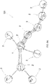
- an electrode system for the multiple acquisition of electrocardiographic derivations is described, which is generally indicated with reference numbers 100, 200 and 300.
- system of the present invention is indicated with three different numbers because three different embodiments will be described, which differ in particular in the configuration of the system and in the relative position of electrodes of the electrode system.
- All three embodiments of the electrode system comprise:
- the supports (4) keep all electrodes (2) close to each other so that the electrode system has a minimum footprint (see Figs. 3 , 4 , 9 , 10 , 11, 12 and 13 ) to allow for easy storage and/or transportation.
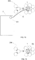
- each support (4) is of removable or separable type, in such a way that, once the support (4) is removed or separated, the two electrodes (2) connected to the support (4) can be moved away from each other and the connector cables (3) can be unrolled and extended in order to use the system (see Figs. 9A , 10A , 14 ).
- the supports (4) are removable or separable, allows to completely free the connector cables (3), in such a way that the operator can position the electrodes (2) in any desired position without any structural constraints.
- the connector cables (3) can be extended in any direction and the electrodes can be positioned in any part of the patient's body.
- the electrodes (2) are of the disposable type.
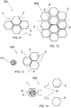
- An electrode (2) of disposable type is shown for illustrative purposes in Fig. 2 .
- the electrode (2) comprises:
- the disk of metallic material is usually made of silver chloride.
- a metallic disk is preferably pre-impregnated with a conductive gel with a base of water and ionic salts that allow a better efficiency in collecting the electric potential.
- Each connector cable (3) comprises a first end, (indicated with a solid circle in Figs. 3 and 4 ) that is electrically connected to the connector (22) of the corresponding electrode (2), and a second end (indicated with a triangle in Figs. 3 and 4 ) that is electrically connected to a corresponding connector obtained in the at least one electrical connection terminal (1).
- said at least one electrical connection terminal (1) may comprise:
- the electrical connection terminal (1) consists of an attachment pad (10) whereon said connectors of the second ends of the connector cables (3) are provided.
- the attachment pad (10) is suitable for being attached to:
- the electrical potentials detected by the electrodes (2) arrive at the electrical connection terminal (1) via the connector cables (3).
- said electrical potentials can be processed in order to obtain information on the patient's cardiac activity.
- the electrode system (100, 200, 300) comprises a coupling body (5) connected to at least one support (4) and comprising a connector (52) coupled with the connector (22) of the electrode (2).
- the connector cable (3) is electrically connected to the connector (52) of the coupling body (5).
- the connector (52) of the coupling body (5) comprises a housing that is suitably shaped to engage with said connection clip of the connector (61) of the electrode (2).
- the coupling body (5) is box-shaped and made of plastic material.
- said attachment pad (10) of the electrical connection terminal (1) is provided on the coupling body (5).
- said support (4) comprises a casing (40) which accommodates the connector cable (3) that is rolled or bent in serpentine configuration.
- the casing (40) comprises a first half-shell (41) and a second half-shell (42) that are separable from each other.
- the casing (40) comprises separable connection means that are interposed between the two half-shells (41, 42) and that allow the two half-shells (41, 42) to be separated from each other so that the casing (40) can be opened and the connector cable (3) disposed therein can be unrolled or extended.
- said separable connection means comprise a removable clamp (43) connected to the two half-shells (41, 42) by means of pre-cut lines.
- the user will have to grasp the removable clamp (43) and pull it away with a force sufficient to overcome the resistance provided by the pre-cut lines.
- the separable connection means comprise interlocking means (44), such as teeth and seats, respectively provided on one half-shell (41) and on the other half-shell (42).
- said support (4) comprises a flat two-dimensional element (45) that extends between the two electrodes and has an adhesive surface whereon the connector cable (3), which is rolled or bent in serpentine configuration, is attached.
- the two-dimensional element may comprise two separable portions (45a, 45b) connected by means of a pre-cut line (46).
- the two-dimensional element (45) may also have one end attached to one electrode (i.e. to the coupling body (5)) and the other end to the other electrode. In such a case, in order to disconnect the two-dimensional element (45) it will be necessary to pull it off completely in the same way as a plaster.
- the coupling bodies (5) and the supports (4) define a compact structure that is easy to store and space-saving.
- the structure can be divided into the different coupling bodies (5), thus allowing the electrodes (2) - which are coupled to the coupling bodies (5) - to be positioned in any position on the patient's body.
- the ECG measurement instrument can be of non-portable or portable type, as shown in Fig. 15 and Fig. 16 respectively.
- the signal receiving and processing system comprises:
- the electronic signal receiving and processing system can be housed in a single device (E2) (if the electrode system comprises only one connection terminal (1)) directly connected and coupled to the connection terminal (1), or in two devices (if the electrode system comprises two connection terminals (1)) directly connected and coupled to the two connection terminals (1).
- the two devices are in communication with each other by means of a cable that electrically connects the two connection terminals, or by means of antennas of the two devices that are coupled together.
- the use of the patient cable or the multi-conductor cable is avoided.
- the portable ECG measurement instrument of Fig. 16 is particularly suitable for a Holter type ECG monitoring.
- the electrode system with the signal receiving and processing system (consisting of one or two devices) is extremely lightweight and does not hinder the daily movements made by a user during an ordinary day.
- the three versions differ in the position and/or in the number of electrodes (2) of which the system is composed (100, 200, 300).
- the electrode system (100) comprises ten electrodes (2) and ten conductor cables (3).
- the electrode system (100) comprises two central electrodes (V1, V2), namely a first central electrode (V1) and a second central electrode (V2).
- V1, V2 a first central electrode
- V2 a second central electrode
- the connection terminal (1) is positioned in correspondence with the second central electrode (V2). It should be noted, however, that nothing would change for the achievement of the objectives pursued by the invention, if the connection terminal (1) were positioned only in the first central electrode (V1) or if the electrode system (100) comprised two connection terminals positioned in the two central electrodes (V1 and V2).
- the ten electrodes comprise eight external electrodes, namely:
- the electrode system (200) of the second embodiment comprises ten electrodes (2) and ten conductor cables (3).
- the electrode system (200) comprises two central electrodes (V1, V2), namely a first central electrode (V1) and a second central electrode (V2).
- V1, V2 a first central electrode
- V2 a second central electrode
- the connection terminal (1) is positioned in correspondence with the second central electrode (V2). It should be noted, however, that nothing would change for the achievement of the objectives pursued by the invention, if the connection terminal (1) were positioned only on the first central electrode (V1) or if the electrode system (200) comprised two connection terminals positioned on the two central electrodes (V1 and V2).
- said ten electrodes comprise eight external electrodes, namely:
- the electrode system (100) of the second embodiment is more reliable than the electrode system (100) of the first embodiment.
- the electrode system (100) of the first embodiment version if a user removes or separates the support (4) that connects the sixth electrode (V4) to the second central electrode (V2) incorrectly or too energetically, there is a possibility that all the connector cables supported by the support (4) will break or will be damaged, resulting in the loss of the signal detected by the sixth (V4), the seventh (V5), and the eighth (V6) electrode.
- a plurality of electrodes (2) is provided, and when the electrode system (300) is in the space-saving configuration, said electrodes (2) are grouped in such a way as to form a honeycomb structure.
- the electrodes (2) can be four (see Fig. 11 ) for fundamental and augmented derivations or can be ten (see Fig. 12 ) for fundamental, augmented, and precordial derivations.
- Figs. 11 and 12 comprises four or ten electrodes
- said electrodes can be of any number according to the requirements of the application in which the electrode system (300) is to be used.
- Figs. 13 and 14 show a system (300) with only three electrodes (2) in the compact configuration ( Fig. 13 ) and in the open configuration with the supports removed or separated ( Fig. 14 ).
- Figs. 13 and 14 schematically show a device (E2) by means of a circle, comprising the signal receiving and processing system applied to the electrical connection terminal (1).
- the electrode system for the multiple acquisition of electrocardiographic derivations makes the installation operation easy and practical, reducing or eliminating the presence of the electrical conductors connecting the individual electrodes to the electrocardiographic system.
- the electrode system (100, 200, 300) provides for the use of removable or separable supports (4), the electrodes can be positioned in any point of the patient's body without the risk of detachment, since no elastic structural element is provided between adjacent electrodes, which would tend to bring the electrode system back to the non-compact configuration.
- the system is inexpensive to make.
Landscapes
- Health & Medical Sciences (AREA)
- Life Sciences & Earth Sciences (AREA)
- Medical Informatics (AREA)
- Biophysics (AREA)
- Pathology (AREA)
- Engineering & Computer Science (AREA)
- Biomedical Technology (AREA)
- Heart & Thoracic Surgery (AREA)
- Physics & Mathematics (AREA)
- Molecular Biology (AREA)
- Surgery (AREA)
- Animal Behavior & Ethology (AREA)
- General Health & Medical Sciences (AREA)
- Public Health (AREA)
- Veterinary Medicine (AREA)
- Cardiology (AREA)
- Measurement And Recording Of Electrical Phenomena And Electrical Characteristics Of The Living Body (AREA)
Applications Claiming Priority (1)
| Application Number | Priority Date | Filing Date | Title |
|---|---|---|---|
| IT202100002276 | 2021-02-03 |
Publications (2)
| Publication Number | Publication Date |
|---|---|
| EP4046573A1 true EP4046573A1 (de) | 2022-08-24 |
| EP4046573B1 EP4046573B1 (de) | 2023-09-06 |
Family
ID=75660151
Family Applications (1)
| Application Number | Title | Priority Date | Filing Date |
|---|---|---|---|
| EP22154296.2A Active EP4046573B1 (de) | 2021-02-03 | 2022-01-31 | Elektrodensystem zur mehrfachen erfassung elektrokardiographischer ableitungen |
Country Status (1)
| Country | Link |
|---|---|
| EP (1) | EP4046573B1 (de) |
Cited By (1)
| Publication number | Priority date | Publication date | Assignee | Title |
|---|---|---|---|---|
| US20230270366A1 (en) * | 2022-02-28 | 2023-08-31 | GE Precision Healthcare LLC | System for electrocardiograph (ecg) electrode count adjustment and associated methods |
Families Citing this family (1)
| Publication number | Priority date | Publication date | Assignee | Title |
|---|---|---|---|---|
| GB202400255D0 (en) * | 2024-01-08 | 2024-02-21 | Gannon Paul | Monitoring and diagnosis by electrocardiography |
Citations (7)
| Publication number | Priority date | Publication date | Assignee | Title |
|---|---|---|---|---|
| US2105089A (en) | 1936-05-07 | 1938-01-11 | United Aircraft Corp | Mechanical syncrronizing device |
| US6415169B1 (en) | 2000-05-31 | 2002-07-02 | General Electric Company | Multiple electrode assembly with extendible electrodes and methods of fabrication and application |
| US7266405B1 (en) | 1999-08-23 | 2007-09-04 | Shl Telemedicine International Ltd. | Compact electrode assembly for a portable ECG signaling device |
| EP2105089A1 (de) * | 2008-03-28 | 2009-09-30 | ANTEA S.r.l. | Elektrodenanordnung für Elektrocardiographie (EKG) |
| US20100076295A1 (en) | 2008-09-24 | 2010-03-25 | General Electric Company | Electrode set for a patient monitoring device |
| CN201537089U (zh) * | 2009-12-01 | 2010-08-04 | 张东晟 | 心电图机导连线保护装置 |
| WO2018157044A1 (en) | 2017-02-25 | 2018-08-30 | CB Innovations, LLC | Emergency cardiac and electrocardiogram electrode placement system |
-
2022
- 2022-01-31 EP EP22154296.2A patent/EP4046573B1/de active Active
Patent Citations (7)
| Publication number | Priority date | Publication date | Assignee | Title |
|---|---|---|---|---|
| US2105089A (en) | 1936-05-07 | 1938-01-11 | United Aircraft Corp | Mechanical syncrronizing device |
| US7266405B1 (en) | 1999-08-23 | 2007-09-04 | Shl Telemedicine International Ltd. | Compact electrode assembly for a portable ECG signaling device |
| US6415169B1 (en) | 2000-05-31 | 2002-07-02 | General Electric Company | Multiple electrode assembly with extendible electrodes and methods of fabrication and application |
| EP2105089A1 (de) * | 2008-03-28 | 2009-09-30 | ANTEA S.r.l. | Elektrodenanordnung für Elektrocardiographie (EKG) |
| US20100076295A1 (en) | 2008-09-24 | 2010-03-25 | General Electric Company | Electrode set for a patient monitoring device |
| CN201537089U (zh) * | 2009-12-01 | 2010-08-04 | 张东晟 | 心电图机导连线保护装置 |
| WO2018157044A1 (en) | 2017-02-25 | 2018-08-30 | CB Innovations, LLC | Emergency cardiac and electrocardiogram electrode placement system |
Cited By (2)
| Publication number | Priority date | Publication date | Assignee | Title |
|---|---|---|---|---|
| US20230270366A1 (en) * | 2022-02-28 | 2023-08-31 | GE Precision Healthcare LLC | System for electrocardiograph (ecg) electrode count adjustment and associated methods |
| US12446816B2 (en) * | 2022-02-28 | 2025-10-21 | GE Precision Healthcare LLC | System for electrocardiogram (ECG) electrode count adjustment and associated methods |
Also Published As
| Publication number | Publication date |
|---|---|
| EP4046573B1 (de) | 2023-09-06 |
Similar Documents
| Publication | Publication Date | Title |
|---|---|---|
| EP0509689B1 (de) | Mehrfach-Elektroden-Band | |
| US5327888A (en) | Precordial electrode strip and apparatus and method using the same | |
| US5307818A (en) | Wireless electrocardiographic and monitoring system and wireless electrode assemblies for same | |
| US8251736B2 (en) | Connector assembly for connecting an electrical lead to an electrode | |
| JP3561858B2 (ja) | 医療用電極体を備えた医療器 | |
| US7272428B2 (en) | Wireless electrocardiograph system and method | |
| CA2864095C (en) | Ecg system with multi mode electrode units | |
| US7826882B2 (en) | Electrode lead set for measuring physiologic information | |
| US7819710B2 (en) | Termination cap for terminating an electrical lead directly to a stud of an electrode and an electrode lead assembly containing such termination cap | |
| EP4046573B1 (de) | Elektrodensystem zur mehrfachen erfassung elektrokardiographischer ableitungen | |
| WO1994001039A9 (en) | Wireless electrocardiographic system and wireless electrode assemblies | |
| JP3104991B2 (ja) | 電極アッセンブリ | |
| KR101780926B1 (ko) | 패치형 심전도 센서 | |
| JP2010075691A (ja) | 患者監視装置用の電極セット | |
| EP1535291A1 (de) | Ekg - verdrahtungssystem | |
| JP2004249107A (ja) | 患者監視システム | |
| JP7236733B2 (ja) | 心電シート、心電測定電極ユニット、心電電極選択評価回路、心電シートの使用方法及び心電シートの製造方法 | |
| GB2291505A (en) | Apparatus for monitoring the electrical activity of a heart | |
| CN208910250U (zh) | 一种十八导联心电图后壁导联连接器 | |
| US20170143224A1 (en) | Module for detecting bodily signals | |
| RO113203B1 (ro) | Electrod pentru biopotenţiale |
Legal Events
| Date | Code | Title | Description |
|---|---|---|---|
| PUAI | Public reference made under article 153(3) epc to a published international application that has entered the european phase |
Free format text: ORIGINAL CODE: 0009012 |
|
| STAA | Information on the status of an ep patent application or granted ep patent |
Free format text: STATUS: THE APPLICATION HAS BEEN PUBLISHED |
|
| AK | Designated contracting states |
Kind code of ref document: A1 Designated state(s): AL AT BE BG CH CY CZ DE DK EE ES FI FR GB GR HR HU IE IS IT LI LT LU LV MC MK MT NL NO PL PT RO RS SE SI SK SM TR |
|
| STAA | Information on the status of an ep patent application or granted ep patent |
Free format text: STATUS: REQUEST FOR EXAMINATION WAS MADE |
|
| 17P | Request for examination filed |
Effective date: 20230221 |
|
| RAV | Requested validation state of the european patent: fee paid |
Extension state: MA Effective date: 20230221 |
|
| RBV | Designated contracting states (corrected) |
Designated state(s): AL AT BE BG CH CY CZ DE DK EE ES FI FR GB GR HR HU IE IS IT LI LT LU LV MC MK MT NL NO PL PT RO RS SE SI SK SM TR |
|
| GRAP | Despatch of communication of intention to grant a patent |
Free format text: ORIGINAL CODE: EPIDOSNIGR1 |
|
| STAA | Information on the status of an ep patent application or granted ep patent |
Free format text: STATUS: GRANT OF PATENT IS INTENDED |
|
| INTG | Intention to grant announced |
Effective date: 20230504 |
|
| RIN1 | Information on inventor provided before grant (corrected) |
Inventor name: CASOLI, GLORIA Inventor name: SCALISE, LORENZO Inventor name: FRANCO, ANTONIO |
|
| GRAS | Grant fee paid |
Free format text: ORIGINAL CODE: EPIDOSNIGR3 |
|
| GRAA | (expected) grant |
Free format text: ORIGINAL CODE: 0009210 |
|
| STAA | Information on the status of an ep patent application or granted ep patent |
Free format text: STATUS: THE PATENT HAS BEEN GRANTED |
|
| AK | Designated contracting states |
Kind code of ref document: B1 Designated state(s): AL AT BE BG CH CY CZ DE DK EE ES FI FR GB GR HR HU IE IS IT LI LT LU LV MC MK MT NL NO PL PT RO RS SE SI SK SM TR |
|
| REG | Reference to a national code |
Ref country code: GB Ref legal event code: FG4D |
|
| REG | Reference to a national code |
Ref country code: CH Ref legal event code: EP |
|
| REG | Reference to a national code |
Ref country code: IE Ref legal event code: FG4D |
|
| REG | Reference to a national code |
Ref country code: DE Ref legal event code: R096 Ref document number: 602022000428 Country of ref document: DE |
|
| REG | Reference to a national code |
Ref country code: NL Ref legal event code: FP |
|
| REG | Reference to a national code |
Ref country code: LT Ref legal event code: MG9D |
|
| P01 | Opt-out of the competence of the unified patent court (upc) registered |
Effective date: 20231206 |
|
| PG25 | Lapsed in a contracting state [announced via postgrant information from national office to epo] |
Ref country code: GR Free format text: LAPSE BECAUSE OF FAILURE TO SUBMIT A TRANSLATION OF THE DESCRIPTION OR TO PAY THE FEE WITHIN THE PRESCRIBED TIME-LIMIT Effective date: 20231207 |
|
| PG25 | Lapsed in a contracting state [announced via postgrant information from national office to epo] |
Ref country code: SE Free format text: LAPSE BECAUSE OF FAILURE TO SUBMIT A TRANSLATION OF THE DESCRIPTION OR TO PAY THE FEE WITHIN THE PRESCRIBED TIME-LIMIT Effective date: 20230906 Ref country code: RS Free format text: LAPSE BECAUSE OF FAILURE TO SUBMIT A TRANSLATION OF THE DESCRIPTION OR TO PAY THE FEE WITHIN THE PRESCRIBED TIME-LIMIT Effective date: 20230906 Ref country code: NO Free format text: LAPSE BECAUSE OF FAILURE TO SUBMIT A TRANSLATION OF THE DESCRIPTION OR TO PAY THE FEE WITHIN THE PRESCRIBED TIME-LIMIT Effective date: 20231206 Ref country code: LV Free format text: LAPSE BECAUSE OF FAILURE TO SUBMIT A TRANSLATION OF THE DESCRIPTION OR TO PAY THE FEE WITHIN THE PRESCRIBED TIME-LIMIT Effective date: 20230906 Ref country code: LT Free format text: LAPSE BECAUSE OF FAILURE TO SUBMIT A TRANSLATION OF THE DESCRIPTION OR TO PAY THE FEE WITHIN THE PRESCRIBED TIME-LIMIT Effective date: 20230906 Ref country code: HR Free format text: LAPSE BECAUSE OF FAILURE TO SUBMIT A TRANSLATION OF THE DESCRIPTION OR TO PAY THE FEE WITHIN THE PRESCRIBED TIME-LIMIT Effective date: 20230906 Ref country code: GR Free format text: LAPSE BECAUSE OF FAILURE TO SUBMIT A TRANSLATION OF THE DESCRIPTION OR TO PAY THE FEE WITHIN THE PRESCRIBED TIME-LIMIT Effective date: 20231207 Ref country code: FI Free format text: LAPSE BECAUSE OF FAILURE TO SUBMIT A TRANSLATION OF THE DESCRIPTION OR TO PAY THE FEE WITHIN THE PRESCRIBED TIME-LIMIT Effective date: 20230906 |
|
| REG | Reference to a national code |
Ref country code: AT Ref legal event code: MK05 Ref document number: 1607416 Country of ref document: AT Kind code of ref document: T Effective date: 20230906 |
|
| PG25 | Lapsed in a contracting state [announced via postgrant information from national office to epo] |
Ref country code: IS Free format text: LAPSE BECAUSE OF FAILURE TO SUBMIT A TRANSLATION OF THE DESCRIPTION OR TO PAY THE FEE WITHIN THE PRESCRIBED TIME-LIMIT Effective date: 20240106 |
|
| PG25 | Lapsed in a contracting state [announced via postgrant information from national office to epo] |
Ref country code: AT Free format text: LAPSE BECAUSE OF FAILURE TO SUBMIT A TRANSLATION OF THE DESCRIPTION OR TO PAY THE FEE WITHIN THE PRESCRIBED TIME-LIMIT Effective date: 20230906 |
|
| PG25 | Lapsed in a contracting state [announced via postgrant information from national office to epo] |
Ref country code: ES Free format text: LAPSE BECAUSE OF FAILURE TO SUBMIT A TRANSLATION OF THE DESCRIPTION OR TO PAY THE FEE WITHIN THE PRESCRIBED TIME-LIMIT Effective date: 20230906 |
|
| PG25 | Lapsed in a contracting state [announced via postgrant information from national office to epo] |
Ref country code: SM Free format text: LAPSE BECAUSE OF FAILURE TO SUBMIT A TRANSLATION OF THE DESCRIPTION OR TO PAY THE FEE WITHIN THE PRESCRIBED TIME-LIMIT Effective date: 20230906 Ref country code: RO Free format text: LAPSE BECAUSE OF FAILURE TO SUBMIT A TRANSLATION OF THE DESCRIPTION OR TO PAY THE FEE WITHIN THE PRESCRIBED TIME-LIMIT Effective date: 20230906 Ref country code: IS Free format text: LAPSE BECAUSE OF FAILURE TO SUBMIT A TRANSLATION OF THE DESCRIPTION OR TO PAY THE FEE WITHIN THE PRESCRIBED TIME-LIMIT Effective date: 20240106 Ref country code: ES Free format text: LAPSE BECAUSE OF FAILURE TO SUBMIT A TRANSLATION OF THE DESCRIPTION OR TO PAY THE FEE WITHIN THE PRESCRIBED TIME-LIMIT Effective date: 20230906 Ref country code: EE Free format text: LAPSE BECAUSE OF FAILURE TO SUBMIT A TRANSLATION OF THE DESCRIPTION OR TO PAY THE FEE WITHIN THE PRESCRIBED TIME-LIMIT Effective date: 20230906 Ref country code: CZ Free format text: LAPSE BECAUSE OF FAILURE TO SUBMIT A TRANSLATION OF THE DESCRIPTION OR TO PAY THE FEE WITHIN THE PRESCRIBED TIME-LIMIT Effective date: 20230906 Ref country code: AT Free format text: LAPSE BECAUSE OF FAILURE TO SUBMIT A TRANSLATION OF THE DESCRIPTION OR TO PAY THE FEE WITHIN THE PRESCRIBED TIME-LIMIT Effective date: 20230906 Ref country code: PT Free format text: LAPSE BECAUSE OF FAILURE TO SUBMIT A TRANSLATION OF THE DESCRIPTION OR TO PAY THE FEE WITHIN THE PRESCRIBED TIME-LIMIT Effective date: 20240108 Ref country code: SK Free format text: LAPSE BECAUSE OF FAILURE TO SUBMIT A TRANSLATION OF THE DESCRIPTION OR TO PAY THE FEE WITHIN THE PRESCRIBED TIME-LIMIT Effective date: 20230906 |
|
| PG25 | Lapsed in a contracting state [announced via postgrant information from national office to epo] |
Ref country code: PL Free format text: LAPSE BECAUSE OF FAILURE TO SUBMIT A TRANSLATION OF THE DESCRIPTION OR TO PAY THE FEE WITHIN THE PRESCRIBED TIME-LIMIT Effective date: 20230906 |
|
| REG | Reference to a national code |
Ref country code: DE Ref legal event code: R097 Ref document number: 602022000428 Country of ref document: DE |
|
| PG25 | Lapsed in a contracting state [announced via postgrant information from national office to epo] |
Ref country code: DK Free format text: LAPSE BECAUSE OF FAILURE TO SUBMIT A TRANSLATION OF THE DESCRIPTION OR TO PAY THE FEE WITHIN THE PRESCRIBED TIME-LIMIT Effective date: 20230906 |
|
| PLBE | No opposition filed within time limit |
Free format text: ORIGINAL CODE: 0009261 |
|
| STAA | Information on the status of an ep patent application or granted ep patent |
Free format text: STATUS: NO OPPOSITION FILED WITHIN TIME LIMIT |
|
| PG25 | Lapsed in a contracting state [announced via postgrant information from national office to epo] |
Ref country code: DK Free format text: LAPSE BECAUSE OF FAILURE TO SUBMIT A TRANSLATION OF THE DESCRIPTION OR TO PAY THE FEE WITHIN THE PRESCRIBED TIME-LIMIT Effective date: 20230906 Ref country code: SI Free format text: LAPSE BECAUSE OF FAILURE TO SUBMIT A TRANSLATION OF THE DESCRIPTION OR TO PAY THE FEE WITHIN THE PRESCRIBED TIME-LIMIT Effective date: 20230906 |
|
| 26N | No opposition filed |
Effective date: 20240607 |
|
| PG25 | Lapsed in a contracting state [announced via postgrant information from national office to epo] |
Ref country code: BG Free format text: LAPSE BECAUSE OF FAILURE TO SUBMIT A TRANSLATION OF THE DESCRIPTION OR TO PAY THE FEE WITHIN THE PRESCRIBED TIME-LIMIT Effective date: 20230906 |
|
| PG25 | Lapsed in a contracting state [announced via postgrant information from national office to epo] |
Ref country code: BG Free format text: LAPSE BECAUSE OF FAILURE TO SUBMIT A TRANSLATION OF THE DESCRIPTION OR TO PAY THE FEE WITHIN THE PRESCRIBED TIME-LIMIT Effective date: 20230906 |
|
| PGFP | Annual fee paid to national office [announced via postgrant information from national office to epo] |
Ref country code: LU Payment date: 20250129 Year of fee payment: 4 Ref country code: NL Payment date: 20250129 Year of fee payment: 4 |
|
| PGFP | Annual fee paid to national office [announced via postgrant information from national office to epo] |
Ref country code: MC Payment date: 20250130 Year of fee payment: 4 |
|
| PGFP | Annual fee paid to national office [announced via postgrant information from national office to epo] |
Ref country code: DE Payment date: 20250129 Year of fee payment: 4 |
|
| PGFP | Annual fee paid to national office [announced via postgrant information from national office to epo] |
Ref country code: IE Payment date: 20250131 Year of fee payment: 4 |
|
| PGFP | Annual fee paid to national office [announced via postgrant information from national office to epo] |
Ref country code: BE Payment date: 20250129 Year of fee payment: 4 Ref country code: CH Payment date: 20250213 Year of fee payment: 4 |
|
| PGFP | Annual fee paid to national office [announced via postgrant information from national office to epo] |
Ref country code: FR Payment date: 20250129 Year of fee payment: 4 |
|
| PGFP | Annual fee paid to national office [announced via postgrant information from national office to epo] |
Ref country code: MT Payment date: 20250129 Year of fee payment: 4 |
|
| PG25 | Lapsed in a contracting state [announced via postgrant information from national office to epo] |
Ref country code: CY Free format text: LAPSE BECAUSE OF FAILURE TO SUBMIT A TRANSLATION OF THE DESCRIPTION OR TO PAY THE FEE WITHIN THE PRESCRIBED TIME-LIMIT; INVALID AB INITIO Effective date: 20220131 |
|
| PG25 | Lapsed in a contracting state [announced via postgrant information from national office to epo] |
Ref country code: TR Free format text: LAPSE BECAUSE OF FAILURE TO SUBMIT A TRANSLATION OF THE DESCRIPTION OR TO PAY THE FEE WITHIN THE PRESCRIBED TIME-LIMIT Effective date: 20230906 |
|
| PGFP | Annual fee paid to national office [announced via postgrant information from national office to epo] |
Ref country code: GB Payment date: 20260126 Year of fee payment: 5 |
|
| PGFP | Annual fee paid to national office [announced via postgrant information from national office to epo] |
Ref country code: IT Payment date: 20260116 Year of fee payment: 5 |
|
| VS25 | Lapsed in a validation state [announced via postgrant information from nat. office to epo] |
Ref country code: MA Free format text: LAPSE BECAUSE OF FAILURE TO SUBMIT A TRANSLATION OF THE DESCRIPTION OR TO PAY THE FEE WITHIN THE PRESCRIBED TIME-LIMIT Effective date: 20230906 |