EP4046579B1 - Endeffektorvorrichtung - Google Patents
Endeffektorvorrichtung Download PDFInfo
- Publication number
- EP4046579B1 EP4046579B1 EP20888473.4A EP20888473A EP4046579B1 EP 4046579 B1 EP4046579 B1 EP 4046579B1 EP 20888473 A EP20888473 A EP 20888473A EP 4046579 B1 EP4046579 B1 EP 4046579B1
- Authority
- EP
- European Patent Office
- Prior art keywords
- assembly
- channel
- end effector
- groove
- convex
- Prior art date
- Legal status (The legal status is an assumption and is not a legal conclusion. Google has not performed a legal analysis and makes no representation as to the accuracy of the status listed.)
- Active
Links
Images


Classifications
-
- A—HUMAN NECESSITIES
- A61—MEDICAL OR VETERINARY SCIENCE; HYGIENE
- A61B—DIAGNOSIS; SURGERY; IDENTIFICATION
- A61B17/00—Surgical instruments, devices or methods
- A61B17/12—Surgical instruments, devices or methods for ligaturing or otherwise compressing tubular parts of the body, e.g. blood vessels or umbilical cord
- A61B17/122—Clamps or clips, e.g. for the umbilical cord
- A61B17/1222—Packages or dispensers therefor
-
- A—HUMAN NECESSITIES
- A61—MEDICAL OR VETERINARY SCIENCE; HYGIENE
- A61B—DIAGNOSIS; SURGERY; IDENTIFICATION
- A61B17/00—Surgical instruments, devices or methods
- A61B17/12—Surgical instruments, devices or methods for ligaturing or otherwise compressing tubular parts of the body, e.g. blood vessels or umbilical cord
- A61B17/122—Clamps or clips, e.g. for the umbilical cord
- A61B17/1227—Spring clips
-
- A—HUMAN NECESSITIES
- A61—MEDICAL OR VETERINARY SCIENCE; HYGIENE
- A61B—DIAGNOSIS; SURGERY; IDENTIFICATION
- A61B17/00—Surgical instruments, devices or methods
- A61B17/12—Surgical instruments, devices or methods for ligaturing or otherwise compressing tubular parts of the body, e.g. blood vessels or umbilical cord
- A61B17/128—Surgical instruments, devices or methods for ligaturing or otherwise compressing tubular parts of the body, e.g. blood vessels or umbilical cord for applying or removing clamps or clips
- A61B17/1285—Surgical instruments, devices or methods for ligaturing or otherwise compressing tubular parts of the body, e.g. blood vessels or umbilical cord for applying or removing clamps or clips for minimally invasive surgery
-
- A—HUMAN NECESSITIES
- A61—MEDICAL OR VETERINARY SCIENCE; HYGIENE
- A61B—DIAGNOSIS; SURGERY; IDENTIFICATION
- A61B17/00—Surgical instruments, devices or methods
- A61B2017/00477—Coupling
-
- A—HUMAN NECESSITIES
- A61—MEDICAL OR VETERINARY SCIENCE; HYGIENE
- A61B—DIAGNOSIS; SURGERY; IDENTIFICATION
- A61B17/00—Surgical instruments, devices or methods
- A61B2017/00526—Methods of manufacturing
- A61B2017/0053—Loading magazines or sutures into applying tools
-
- A—HUMAN NECESSITIES
- A61—MEDICAL OR VETERINARY SCIENCE; HYGIENE
- A61B—DIAGNOSIS; SURGERY; IDENTIFICATION
- A61B17/00—Surgical instruments, devices or methods
- A61B17/12—Surgical instruments, devices or methods for ligaturing or otherwise compressing tubular parts of the body, e.g. blood vessels or umbilical cord
- A61B2017/12004—Surgical instruments, devices or methods for ligaturing or otherwise compressing tubular parts of the body, e.g. blood vessels or umbilical cord for haemostasis, for prevention of bleeding
Definitions
- the present disclosure relates to medical instruments, and more particularly, relates to an end effector instrument.
- an end effector device such as a hemostatic clip, ligation clip, etc.
- the end effector device may clamp human tissue to achieve the function of surgical hemostasis or ligation.
- the commonly used end effector device has a complicated structure after being closed, and the production cost is high.
- an assembly of the end effector device and the delivery device usually needs to be done manually, which is inefficient.
- WO2018201406A1 discloses an end portion execution instrument, comprising: an end portion execution device, the end portion execution device comprising a clip and an elastic portion, the elastic portion being provided with a sleeve hole, and the elastic portion being provided with a limiting protrusion; a delivery device, the delivery device comprising a sheath tube and a mandrel, the sheath tube being provided with a passage, while the mandrel is arranged within the passage of the sheath tube; a distal end of the mandrel is provided with a connecting end, and the sheath tube is provided with a limiting recess.
- US 2017 296197 A1 relates to a clip device for endoscope for holding and placing an indwelling clip comprising an outer tubular body and an inner tubular body provided in the outer tubular body.
- the end effector instrument includes: an end effector device, the end effector device comprising an effector portion configured to perform a specified operation; and a delivery device connected to the end effector device, the delivery device is configured to deliver the end effector device to a target region where the specified operation is to be performed.
- the delivery device includes an operation portion. The operation portion is configured to drive the effector portion to perform the specified operation.
- the end effector device includes an accommodation portion.
- the accommodation portion is configured to partially accommodate the effector portion.
- the delivery device includes a delivery pipe.
- the accommodation portion may be releasably connected to the delivery pipe.
- the accommodation portion includes a first connecting portion.
- the delivery pipe includes a second connecting portion.
- the second connecting portion connects the first connecting portion to establish a connection between the delivery device and the end effector device.
- the accommodation portion includes an inner pipe and an outer pipe. At least a portion of the outer pipe fits snugly over the inner pipe.
- the first connecting portion may be located on the inner pipe.
- the first connecting portion may include a limiting convex.
- the second connecting portion may include a limiting concave.
- the end effector device and the delivery device may be configured such that: when the limiting convex extends into the limiting concave, the end effector device is connected to the delivery device; and when the limiting convex retracts from the limiting concave, the end effector device is disconnected from the delivery device.
- the limiting convex and the accommodation portion may be integrally formed.
- the operation portion may include a shaft positioned within the delivery pipe. An end of the shaft may enter into or retract from the accommodation portion. When the end of the shaft enters into the accommodation portion, the limiting convex may be compressed by a connecting end to enter into the limiting concave. When the end of the shaft retracts from the accommodation portion, the limiting convex may retract from the limiting concave.
- one end of the shaft may include a connecting end.
- An outer diameter of the connecting end may exceed an inner diameter of the limiting convex.
- the effector portion may include a lock connecting portion.
- the accommodation portion may include a locking portion.
- the locking portion may be configured to connect the lock connecting portion. When the locking portion connects the lock connecting portion, the effector portion and the accommodation portion may be fixed relative to each other.
- the accommodation portion may include a guiding groove located along an axial direction.
- the lock connecting portion may be configured to slide within the guiding groove.
- the accommodation portion may include an inner pipe and an outer pipe.
- the locking portion may be located on the outer pipe.
- the guiding groove may be configured on the inner pipe.
- the locking portion may include an elastic piece. One end of the elastic piece may be fixedly connected to the accommodation portion, and another end of the elastic piece may extend into an interior of the accommodation portion.
- the locking portion may include an elastic piece. One end of the elastic piece may be fixedly connected to the outer pipe, and another end of the elastic piece may extend into an interior of the inner pipe.
- an end of the guiding groove away from the effector portion may have a positioning convex.
- a distance between the positioning convex and the effector portion may exceed a distance between the locking portion and the effector portion.
- a retaining portion may be located on the positioning convex.
- the retaining portion may include a fixed end and a free end.
- the fixed end of the retaining portion may be fixedly connected to the positioning convex.
- the free end of the retaining portion may face an interior of the guiding groove.
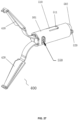
- the effector portion includes a clip.
- the clip may include a first clip arm, a second clip arm, and a connecting pin.
- the first clip arm and the second clip arm may be connected through the connecting pin.
- the lock connecting portion may be formed by one end or both ends of the connecting pin.
- the clip may also include an elastic ring.
- the elastic ring may fit snugly over the connecting pin.
- the elastic ring may be located between the first clip arm and the second clip arm.
- an end of the first clip arm close to the connecting pin may have a first bending portion that bends towards the second clip arm.
- the first bending portion may have a first hole.
- One end of the second clip arm close to the connecting pin may have a second bending portion that bends towards the first clip arm.
- the second bending portion may have a second hole. The first hole and the second hole may at least partially overlap.
- the shaft may include a large-diameter portion and a small-diameter portion.
- the small-diameter portion of the shaft may be fixedly connected to the connecting end.
- the large-diameter portion of the shaft may be fixedly connected to the small-diameter portion of the shaft.
- a diameter of the large-diameter portion of the shaft may exceed a diameter of the small-diameter portion of the shaft.
- a first hole and a second hole may at least partially overlap and communicate to form a connecting hole.
- the diameter of the large-diameter portion of the shaft may exceed a diameter of an inner diameter of the connecting hole.
- the diameter of the small-diameter portion of the shaft may be smaller than the inner diameter of the connecting hole.
- the end effector instrument may further include: an assembly device configured to assemble the end effector device and the delivery device to establish a connection between the end effector device and the delivery device.
- the assembly device may include an assembly box configured to fix the end effector device and the delivery device when the end effector device and the delivery device are assembled.
- the assembly box may include: an accommodation portion configured to accommodate the end effector device; an assembly groove configured to accommodate the delivery device to achieve an assembly of the delivery device and the end effector device; and a joint portion configured to fix the delivery device in the assembly groove.
- the joint portion may include a first portion and a second portion.
- the first portion of the joint portion may extend beyond an outer surface of the assembly groove. After the first portion of the joint portion is pressed, the second portion of the joint portion may enter into an interior of the assembly groove.
- the assembly device may further include an assembly tool.
- the assembly tool may include at least one groove.
- the assembly box may be configured to enter into or retract from the at least one groove.
- one of the at least one groove of the assembly tool may include a first channel.
- a height of the first channel may be smaller than or equal to a height of the joint portion. When the joint portion enters into the first channel, the first channel may press the first portion of the joint portion.
- the groove may further include a second channel.
- the second channel may be in communication with the first channel.
- the second channel may be located at an entrance end of the first channel.
- a height of the second channel may gradually decrease along a direction from the entrance end to the first channel.
- the groove may further include a third channel.
- the third channel is in communication with the first channel.
- the third channel may be located at an exit end of the first channel.
- a height of the third channel may exceed a height of the first channel.
- a convex portion may be located outside the assembly box, the convex portion being elastic.
- the convex portion may be in a compressed state when the convex portion is positioned within the first channel.
- the convex portion may be in an original state when the convex portion is positioned within the third channel.
- the third channel may be configured with an elastic component.
- the elastic component may be configured to apply a bias pressure to the assembly box along a first direction so as to cause the assembly box to retract from the third channel.
- the end effector device may include an expanding window.
- the assembly box may include an operating window and an expanding portion; the operating window may be in communication with the expanding window.
- the expanding portion may be configured to extend into an interior of the effector device through the operation window and the expanding window to facilitate establishing a connection between the end effector device and the delivery device.
- the assembly groove may include a groove slot and a limiting slot.
- the groove slot may be located at a side of the assembly groove.
- the limiting slot may be in communication with the groove slot.
- a width of the limiting slot may be smaller than a width of the assembly groove.
- the assembly box may include a limiting portion.
- the limiting portion may be configured to limit a relative movement between the delivery device and the assembly box.
- the assembly box may include a housing.
- the limiting portion of the assembly box may be located on the housing.
- the delivery device may include a delivery pipe.
- the limiting portion of the assembly box may be configured to limit a relative movement between the delivery pipe and the housing.
- the limiting portion of the assembly box may include at least one of a groove body, a limiting channel, or a buckle.
- the limiting portion of the assembly box may be configured with at least one convex point.
- Some embodiments of the present disclosure provides an assembly method of an end effector instrument in any embodiments of the present disclosure.
- controlling the assembly box to enter into the at least one groove of the assembly tool may include: controlling the convex portion of the assembly box to enter into the first channel through the second channel; controlling the convex portion of the assembly box to enter into the third channel through the first channel and to obtain first feedback information; and in response to the first feedback information, stopping moving the assembly box.
- the third channel may include the elastic component.
- the controlling the assembly box to enter into the at least one groove of the assembly tool may include: controlling the convex portion of the assembly box to enter into the first channel from the second channel; controlling the convex portion to enter into the third channel from the first channel and to obtain third feedback information; and in response to the third feedback information, stopping moving the assembly box.
- controlling the assembly box and the delivery pipe to continue to move towards the interior of the at least one groove of the assembly tool to axially fix the delivery pipe in the assembly groove may include: controlling the joint portion of the assembly box to enter into the first channel; controlling the first channel to press the first portion of the joint portion, such that the second portion of the joint portion enters into the assembly groove; and controlling the second portion of the joint portion to press the delivery pipe, such that the delivery pipe is axially fixed in the assembly groove.
- controlling the shaft of the delivery device to move towards the end effector device to achieve the second assembly with the clip of the effector portion may include: controlling a connecting end of the shaft to enter into the accommodation portion, such that the limiting convex of the accommodation portion extends into the limiting concave of the delivery pipe to establish a connection between the accommodation portion and the delivery pipe; and controlling a large-diameter portion of the shaft to extend into a connecting hole of the clip of the effector portion to establish a connection between the shaft and the clip.
- the retracting the assembled end effector device and the delivery device from the assembly box may include: driving the assembly box to move from the interior of the at least one groove of the assembly tool to an exterior of the at least one groove, and obtaining second feedback information; and retracting the end effector device and the delivery device from the assembly groove based on the second feedback information.
- the retracting the assembled end effector device and the delivery device from the assembly box may include: driving the assembly box to move from the interior of the at least one groove to an exterior of the at least one groove, and obtaining fourth feedback information; and retracting the end effector device and the delivery device from the assembly groove based on the fourth feedback information.
- system means for distinguishing different components, elements, parts, sections or assembly of different levels.
- device means for separating components, elements, parts, sections or assembly of different levels.
- module means for separating components, elements, parts, sections or assembly of different levels.
- block means for separating components, elements, parts, sections or assembly of different levels.
- the terms may be displaced by another expression if they achieve the same purpose.
- a flowchart is used in the present disclosure to illustrate the operation performed by the system according to the embodiment of the present disclosure. It should be understood that the previous or subsequent operations are not necessarily performed accurately in order. Instead, the steps may be processed in reverse order or simultaneously. These steps may be added to or removed from another procedure.
- the present disclosure may provide an end effector instrument.
- the end effector instrument may be configured to perform a surgical operation in minimally invasive surgery, such as surgical hemostasis, ligation, or the like.
- the end effector instrument may include an end effector device and a delivery device.
- the end effector device may be configured to clamp human tissue to achieve the function of the surgical hemostasis or the ligation.
- the delivery device may be configured to deliver the end effector device to a lesion in a patient.
- the end effector device may be maintained at the lesion to keep the lesion ligated.
- the end effector device and the delivery device may be an integrated design (also referred to as "an integral end effector instrument").
- the integrated design of the end effector device and the delivery device may be all for one-time use, which may lead to a higher cost and more medical waste, and in turn be not economical or environmentally friendly.
- the end effector device and delivery device may be a disintegrated design (also referred to as "a disintegrated end effector instrument").
- the end effector device may be for one-time use, and the delivery device may be reused, which may further save the cost, reduce the generation of medical waste, and be economical and environmentally friendly.
- the end effector device in order to connect the end effector device to the delivery device during an assembly, may include an accommodation pipe.
- the accommodation pipe may include a positioning groove configured to establish the connection to the delivery device.
- it may be difficult to manufacture the accommodation pipe with the positioning groove.
- An accommodation pipe of the end effector instrument includes an inner pipe and an outer pipe.
- the inner pipe replaces the role of a positioning groove to establish a connection to and release with a delivery device.
- the accommodation pipe is divided into the inner pipe and the outer pipe. After fine structures are made on the inner pipe and the outer pipe, respectively, the outer pipe fits snugly over the inner pipe, such that the inner pipe and the outer pipe form the accommodation pipe, which is convenient for production and manufacture, and particularly be beneficial to the manufacture of a small device for an endoscopic operation such as the end effector instrument.
- the assembly between the end effector device and the delivery device needs to be completed manually by an operator, and the assembly efficiency and success rate is relatively low.
- the end effector instrument of some embodiments of the present disclosure further provide an assembly device.
- the assembly device includes an assembly box and an assembly tool which is configured to complete the assembly between the end effector device and the delivery device, improving the assembly efficiency.
- FIG. 1 is a block diagram illustrating an end effector instrument according to some embodiments of the present disclosure.
- the end effector instrument 10 includes an end effector device 11 and a delivery device 12.
- the end effector device 11 includes an effector portion configured to perform a specified operation.
- the delivery device 12 be connected to the end effector device 11.
- the delivery device 12 is configured to deliver the end effector device 11 to a target area where the specified operation is to be performed.
- the delivery device 23 includes an operation portion.
- the operation portion drives the effector portion to perform the specified operation.
- the specified operation is a medical operation in minimally invasive surgery, such as surgical hemostasis, ligation, etc.
- the effector portion of the end effector device 11 is a medical instrument for performing a related operation, such as a hemostatic clip, a ligature clip, etc.
- the target area is an area within a target object where the specified operation needs to be performed.
- the target object includes a biological object and a non-biological object.
- the biological object includes a human being, an animal, a plant, etc.
- the non-biological object includes an experimental model (e.g., an organ model, etc.).
- the area within the target object where the specified operation needs to be performed is a lesion area in the human being or the animal.
- an operating portion of the delivery device 12 includes an operating handle. Specifically, an operator (e.g., a doctor) operates the operating handle to control the end effector device 11 to perform an operation such as surgical hemostasis, ligation, etc.
- the end effector device 11 and the delivery device 12 are integrally designed or fixedly connected for direct usage.
- the end effector device 11 and the delivery device 12 be a disintegrated design, which is assembled to complete the connection during usage.
- the end effector device 11 includes an accommodation portion configured to partially accommodate the effector portion.
- the delivery device 12 includes a delivery pipe.
- the accommodation portion and the delivery pipe are releasably connected to complete the assembly of the end effector device 11 and the delivery device 12.
- the accommodation portion and the delivery pipe be magnetically attracted together.
- at least one of the accommodation portion and the delivery pipe include an electromagnet or a coil, and another one includes a magnetic material or an electromagnet and a coil to power the accommodation portion and/or the delivery pipe respectively, which make the accommodation portion and/or the delivery pipe magnetic.
- the accommodation portion and the delivery pipe are attracted together to establish the connection between the accommodation portion and the delivery pipe.
- the accommodation portion and the delivery pipe are not powered on, the accommodation portion and/or the delivery pip are not magnetic, the accommodation portion be separated from the delivery pipe.
- the accommodation portion and the delivery pipe are connected by a threaded connection.
- the delivery pipe has an internal thread.
- the accommodation portion has an external thread corresponding to the internal thread.
- the delivery pipe be screwed into the accommodation portion.
- the connection or separation between the end effector device 11 and the delivery device 12 be realized by tightening or loosening the delivery pipe.
- the end effector instrument 10 also includes an assembly device 13.
- the assembly device 13 is configured to assemble the end effector device 11 and the delivery device 12 to establish the connection between the end effector device 11 and the delivery device 12.
- the assembly device 13 includes an assembly box configured to fix the end effector device 11 and the delivery device 12 when the end effector device 11 and the delivery device 12 are assembled.
- the assembly box includes a joint portion configured to fix the end effector device 11 and the delivery device 12 after the joint portion is pressed. The operator presses the joint portion to fix the end effector device 11 and the delivery device 12.
- the assembly device 13 also includes an assembly tool configured to facilitate the assembly box achieving the assembly and fixation of the end effector device 11 and the delivery device 12.
- the assembly tool includes at least one groove.
- the assembly box enters into or retracts from the at least one groove to achieve the assembly of the delivery device 12 and the end effector device 11 in the assembly box to complete the assembly of the end effector instrument 10.
- a plurality of delivery devices 12 be assembled with end effector devices 11 in a plurality of assembly boxes simultaneously to complete the assembly of a plurality of end effector instruments 10.
- the end effector instrument 10 also omits the assembly device 13. The operator assembles the end effector instrument 10 manually to establish the releasable connection between the end effector device 11 and the delivery device 12.
- a limiting convex (e.g., a limiting convex 520) be positioned on the accommodation portion in the end effector device 11.
- a limiting concave be positioned on a delivery pipe of the delivery device 12. The operator pushes a shaft of the delivery device 12 to make a connecting end on the shaft abut the limiting convex. The limiting convex be pressed to extend into the limiting concave on the delivery pipe.
- connection between the limiting convex and the limiting concave prevents a relative movement between the delivery pipe and the accommodation portion to complete the connection between the end effector device 11 and the delivery device 12.
- the connecting end of the shaft is relieved from abutting the limiting convex.
- the limiting convex retracts from the limiting concave, thereby completing the separation of the end effector device 11 and the delivery device 12.
- the accommodation portion on the end effector device 11 includes a first connecting portion.
- the delivery pipe on the delivery device 12 includes a second connecting portion.
- the second connecting portion connects the first connecting portion to complete the connection between the delivery device 12 and the end effector device 11.
- the accommodation portion and the first connecting portion are an integrated design.
- the delivery pipe and the second connecting portion are also an integrated design.
- the first connecting portion is an external thread on the accommodation portion.
- the second connecting portion is an internal thread on the delivery pipe corresponding to the external thread of the accommodation portion.
- the first connecting portion and the second connecting portion are connected or separated through a thread connection manner.
- the first connecting portion is a convex structure on the accommodation portion.
- the second connecting portion is a concave structure on the delivery pipe corresponding to the convex structure.
- the convex structure and the concave structure are formed on the accommodation portion and the delivery pipe by a stamping mold, respectively.
- the accommodation portion and the first connecting portion are also a disintegrated design.
- the delivery pipe and the second connecting portion also have a disintegrated design.
- the first connecting portion be an elastic ring arranged inside the accommodation portion or fitting snugly over the accommodation portion.
- the elastic ring has a concave structure or a convex structure, which be used for identifying the position of the accommodation portion and also for connecting the second connecting portion (a convex structure or a concave structure).
- the first connecting portion is a shaft sleeve. One end of the shaft sleeve be configured to assemble the accommodation portion. Another end of the shaft sleeve is configured to assemble the delivery pipe.
- the accommodation portion includes an accommodation pipe 500.
- the accommodation pipe 500 includes an inner pipe 502 and an outer pipe 501. At least a portion of the outer pipe 501 fits snugly over the inner pipe 502.
- the first connecting portion is positioned on the inner pipe 502.
- an inner diameter of the outer pipe 501 and an outer diameter of the inner pipe 502 are substantially the same.
- the outer pipe 501 and the inner pipe 502 are connected by way of an interference fit to form the accommodation portion.
- the first connecting portion and the inner pipe 502 are an integrated design.
- the first connecting portion is an internal thread positioned on the inner pipe 502.
- the first connecting portion is a convex structure stamped on the inner pipe 502.
- the inner pipe 502 and the outer pipe 501 be fabricated from two pipe structures and then the inner pipe 502 and the outer pipe 501 be assembled together, or the inner pipe 502 and the outer pipe 501 be processed on a single pipe structure, respectively.
- the material of the outer pipe 501 includes but is not limited to, stainless steel, titanium, tantalum, platinum, palladium, etc.
- the material of the inner pipe 502 includes but is not limited to, stainless steel, titanium, tantalum, platinum, palladium, etc.
- the material of the outer pipe 501 is the same as that of the inner pipe 502.
- the material of the outer pipe 501 also be different from that of the inner pipe 502.
- the outer pipe 501 is made of titanium with a relatively high strength
- the inner pipe 502 is made of stainless steel with a high toughness.
- the delivery pipe include a sheath 200.
- the second connecting portion is positioned at a distal end of the sheath 200.
- the orientation refers to a length direction of the end effector instrument 10 (since the end effector device 11 is transported, through the delivery device 12, to a human body for implementing surgical ligation, and the delivery device 12 usually have a long line shape), or be along a direction that the end effector instrument 10 enters into the human body.
- a side close to the operator be the "proximal end.”
- a side extending into the human body to perform an operation be the "distal end.”
- the "proximal end” and the “distal end” should not be understood as only representing ends.
- the first connecting portion may include a limiting convex 520.
- the second connecting portion may include a limiting concave 202.
- the limiting convex 520 may enter into or retract from the limiting concave 202.
- the limiting concave 202 may correspond to the limiting convex 520 one by one.
- the limiting concave 202 and the limiting convex 520 may limit each other.
- the limiting convex 520 may be integrally formed with the accommodation portion.
- the limiting convex 520 may be a convex structure integrally formed on the accommodation portion.
- the limiting convex 520 may also be a convex structure integrally formed on the inner pipe 502. In some embodiments, the limiting convex 520 may have a certain bending elasticity.
- an operation portion of the delivery device may press the limiting convex 520.
- the limiting convex 520 may be elastically deformed and extend into an interior of the limiting concave 202 of the delivery pipe.
- the limiting convex 520 may automatically rebound due to an elastic effect, so that the limiting convex 520 may retract from the limiting concave 202.
- the operation portion may include a shaft connected to an operation handle, and the shaft may press the limiting convex 520.
- the limiting convex 520 may also include other structures that may move towards the limiting concave 202, which may be non-limiting in the present disclosure.
- the limiting convex 520 may include a convex structure rotatable axially along the inner pipe 502.
- the limiting convex 520 may include a telescopic structure retractable along a radial direction of the inner pipe 502.
- the limiting concave 202 may be a blind hole, a through-hole, or a groove configured on a side wall of the delivery pipe.
- a step extending towards a central axis of the delivery pipe may be arranged on an inner wall of the delivery pipe.
- the limiting concave 202 may be formed between the step and the inner wall of the delivery pipe to limit the limiting concave 520.
- the delivery pipe and the accommodation portion may be connected, and the end effector device 11 may be connected to the delivery device 12.
- the limiting convex 520 moves out of the limiting concave 202, the delivery pipe and the accommodation portion may be separated, and the end effector device 11 may be disconnected from the delivery device 12.
- the first connecting portion may include the limiting concave 202 and the second connecting portion may include the limiting convex 520.
- the effector portion in the end effector device 11 may be configured to perform a specified operation during surgery, such as surgical hemostasis, ligation, etc.
- the effector portion may include a clip 400, such as a hemostatic clip, ligation clip, or the like.
- the end effector device 11 may include a clip 400 and an accommodation pipe 500.
- the accommodation pipe 500 may be configured with a channel.
- the inner pipe 502 and the outer pipe 501 may be configured with a channel, respectively.
- the channels of the inner pipe 502 and the outer pipe 501 may be connected to form the channel of the accommodation pipe 500.
- the clip 400 may be accommodated into the channel of the accommodation pipe 500 from a distal end.
- An outer wall of the inner pipe 502 may be configured with a limiting convex 520.
- the limiting convex 520 may be configured to cooperate with the limiting concave 202 to complete the connection and release between the sheath 200 and the inner pipe 502.
- the accommodation pipe 500 may be divided into the inner pipe 502 and the outer pipe 501. After fine structures are made on the inner pipe 502 and the outer pipe 501 respectively, the outer pipe 501 may fit snugly over the inner pipe 502, so that the inner pipe 502 and the outer pipe 501 may form the accommodation pipe 500, which may be convenient for production and manufacturing, and particularly be beneficial to the manufacture of a small device for an endoscopic operation such as the end effector instrument 10.
- the inner pipe 502 may be configured with the channel, and the outer pipe 501 may also be configured with the channel. As long as the inner pipe 502 and the outer pipe 501 are connected together, a depth of the inner pipe 502 inserted into the outer pipe 501 may be set arbitrarily according to actual needs.
- the channel of the inner pipe 502 may be connected to the channel of the outer pipe 501.
- the channel of the inner pipe 502 and the channel of the outer pipe 501 may constitute a movement channel of the clip 400 together.
- the clip 400 may enter into the movement channel from the distal end.
- the effector portion may include a lock connecting portion.
- the accommodation portion may include a locking portion 511 connecting to the lock connecting portion.
- the lock connecting portion may be an independent structure on the effector portion and fixedly connected to other structures on the effector portion to complete the connection to the locking portion 511, thereby realizing the relative fixation between the effector portion and the accommodation portion.
- the lock connecting portion may also be a structure in the effector portion.
- the lock connecting portion may also play other roles in the effector portion.
- the lock connecting portion may also be configured to connect two clip arms of the clip 400.
- the lock connecting portion may be a structure in the effector portion.
- the effector portion may include the clip 400.
- the clip 400 may include a first clip arm 410, a second clip arm 420, and a connecting pin 601.
- the first clip arm 410 and the second clip arm 420 may be pinned through the connecting pin 601.
- one end of the connecting pin 601 may form the lock connecting portion.
- both ends of the connecting pin 601 may form the lock connecting portion, respectively.
- the lock connecting portion may be a locking convex 602.
- the clip 400 may include a first clip arm 410, a second clip arm 420, and a connecting pin 601.
- the first clip arm 410 and the second clip arm 420 may be connected through the connecting pin 601.
- both ends of the connecting pin 601 may form the locking convex 602, respectively, which may be non-limiting.
- one end of the connecting pin 601 may form the locking convex 602.
- the connecting pin 601 may not only connect the first clip arm 410 and the second clip arm 420 but also lock the clip 400, and the structure may be simple.
- the effector portion may also include an elastic ring 402.
- the elastic ring 402 may fit snugly over the connecting pin 601 and be positioned between the first clip arm 410 and the second clip arm 420.
- the elastic ring 402 may be a spring or any structure having elastic.
- the elastic ring 402 when the clip 400 may be clamped (or an opening and closing angle becoming smaller), the elastic ring 402 may be compressed by the first clip arm 410 and the second clip arm 420; when the clip 400 is released, the elastic ring 402 may provide an elastic force for the first clip arm 410 and the second clip arm 420, so that the first clip arm 410 and the second clip arm 420 may be away from each other at a position abutting the elastic ring (or the opening and closing angle becoming larger).
- a direction of the elastic force of the elastic ring 402 may refer to a direction in which the first clip arm 410 and the second clip arm 420 are away from each other at the position abutting the elastic ring 402.
- the elastic ring 402 may be a helicoidal spring.
- the helicoidal spring may fit snugly over the connecting pin 601 through its helicoidal circle.
- the effector portion may omit the elastic ring, and the first clip arm 410 and the second clip arm 420 may be away from each other by their elastic force.
- the locking portion 511 may include an elastic piece 510. One end of the elastic piece 510 may be fixedly connected to the accommodation portion, and another end of the elastic piece 510 may extend into an interior of the accommodation portion.
- the accommodation pipe 500 may be an integrated pipe body.
- the elastic piece 510 may be arranged on the accommodation pipe 500.
- one end of the elastic piece 510 may be fixedly connected to a side wall of the accommodation pipe 500, and another end of the elastic piece 510 may extend into the channel of the accommodation portion. It should be understood that the channel of the accommodation portion may be an internal space of the accommodation pipe 500.
- the locking portion 511 may be integrally formed with the accommodation portion.
- the elastic piece 510 may be formed on the side wall of the accommodation pipe 500 by laser cut, which may require that the material of the outer pipe 501 has a certain elasticity.
- the locking portion 511 and the accommodation portion may be a disintegrated design.
- a groove hole capable of accommodating the elastic piece 510 may be cut on the side wall of the accommodation pipe 500, and then one end of the elastic piece 510 may be fixed at an edge of the groove hole in a gluing manner, a welding manner, or a fastener fixation manner, while another end of the elastic piece 510 may be in a free state, so that the elastic piece 510 may extend into the channel of the accommodation portion.
- an end of the elastic piece 510 fixedly connected to the accommodation portion may be a proximal end, i.e., an end close to the operator.
- the accommodation pipe 500 may include the outer pipe 501 and the inner pipe 502.
- the outer pipe 501 may be configured with the elastic piece 510.
- the inner pipe 502 and the outer pipe 501 may be configured with a channel, respectively.
- the channels of the inner pipe 502 and the outer pipe 501 may be connected to form a channel of the accommodation pipe 500.
- At least a portion of the elastic piece 510 may extend into the channel of the accommodation pipe 500 and form the locking portion 511.
- both ends of the connecting pin 601 form the locking convex 602
- the clip 400 may be configured with a locking convex 602, i.e., both ends of the connecting pin 601 may form the locking convex 602, which may respectively correspond to the locking portion 511 on the two elastic pieces 510.
- the locking convex 602 may be configured to lock a positional relationship between the clip 400 and the accommodation pipe 500 to prevent the clip 400 from opening by moving from the distal end of the accommodation pipe 500.
- the clip 400 may enter into the channel of the accommodation pipe 500 from the distal end of the accommodation pipe 500.
- the locking convex 602 When the locking convex 602 is positioned at a distal end of the locking portion 511, the clip 400 may move towards the distal end of the accommodation pipe 500.
- the clip 400 When the clip 400 is moved from the distal end to the proximal end, the clip 400 may be gradually closed under the compressing of the accommodation pipe 500.
- the locking convex 602 may press the locking portion 511 outward.
- the elastic piece 510 may deform to make the locking portion 511 bulge to make room for the locking convex 602, so that the locking convex 602 may move to a proximal end of the locking portion 511 through the locking portion 511.
- the clip 400 may be closed and the locking portion 511 may be positioned at a distal end of the locking convex 602.
- the locking portion 511 may rebound.
- the locking portion 511 may extend into the accommodation pipe 500.
- the locking portion 511 may be positioned on a path of the locking convex 602 moving to the distal end to prevent the locking convex 602 from moving to the distal end.
- the clip 400 may be locked by the locking convex 602 and the locking portion 511.
- the clip 400 may be unable to move to the distal end of the accommodation pipe 500, avoiding reopening after the clip 400 is closed.
- the structure of the elastic piece 510 and the locking portion 511 may be simple.
- the rebounding of the elastic piece 510 may refer to that: during the compressing of the locking convex 602, the locking portion 511 may be bulged; after the locking convex 602 passes over the locking portion 511, the locking portion 511 may rebound to block the locking portion 511. It may not mean that the elastic piece 510 must be made of an elastic material.
- the elastic piece 510 may be made of any material.
- the material of the elastic piece 510 may be the same as that of the accommodation pipe 500.
- the elastic piece 510 may be a part of the side wall of the accommodation pipe 500 after cutting.
- One end of the elastic piece 510 may be connected to the side wall of the accommodation pipe 500, and another end of the elastic piece 510 may extend into the channel of the accommodation pipe 500.
- the accommodation portion in order to facilitate the movement of the effector portion relative to the accommodation portion, the accommodation portion may be configured with a guiding groove 503 along an axial direction.
- the guiding groove 503 may be opened on the inner pipe 502 of the accommodation portion.
- the guiding groove 503 may be formed on a side wall of the inner pipe 502 by laser cut.
- the lock connecting portion may slide in the guiding groove 503.
- the locking portion 511 may extend into the guiding groove 503.
- the guiding groove 503 may guide the lock connecting portion to move to a position where the locking portion 511 is positioned to complete the connection between the locking portion 511 and the lock connecting portion.
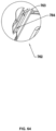
- an end of the guiding groove 503 away from the effector portion may be configured with a positioning convex 505.
- a distance between the positioning convex 505 and the effector portion may be greater than a distance between the locking portion 511 and the effector portion, i.e., the locking portion 511 may be positioned between the positioning convex 505 and the effector portion. It should be understood that a distance between the positioning convex 505 and the effector portion and a distance between the locking portion 511 and the effector portion may be distances of the positioning convex 505 and the locking portion 511 to a nearest end of the effector portion.
- the locking portion 511 when the lock connecting portion moves to a proximal end along the guiding groove 503, the locking portion 511 may be connected to the lock connecting portion to prevent the lock connecting portion from not moving to the distal end, and the positioning convex 505 may prevent the further movement of the lock connecting portion to the proximal end, i.e., a position of the effector portion may be constrained by the locking portion 511 and the positioning convex 505 at the same time, and may not move to the proximal end or the distal end to maintain at a usage state (e.g., a closed state) when the effector portion performs the specified operation, and maintain the stability of the effector portion in the usage state.
- a usage state e.g., a closed state
- the inner pipe 502 may be configured with the guiding groove 503.
- the locking convex 602 may slide in the guiding groove 503.
- the guiding groove 503 may guide the locking convex 602 to move to the position of the locking portion 511, facilitating the locking.
- the locking portion 511 may extend into the guiding groove 503.
- the guiding groove 503 may be configured with a positioning convex 505.
- the positioning convex 505 may be positioned at the proximal end of the locking portion 511.
- the locking convex 602 may be positioned between the positioning convex 505 and the locking portion 511. In some embodiments, as shown in FIG.
- a height of the locking convex 602 may be H 2
- a height of the locking portion may be H 1
- a height of the positioning convex may be H 3.
- the locking portion 511 may restrict the locking convex 602 from moving to the distal end
- the positioning convex 505 may restrict the locking convex 602 from moving to the proximal end, so that the position of the clip 400 may be constrained by the locking portion 511 and the positioning convex 505 at the same time, and may not move to the proximal or the distal end, so that the clip 400 may be in the closed state, and the closed state of the clip 400 may be stable.
- the accommodation portion may omit the inner pipe 502 and the outer pipe 501 but may be arranged as an accommodation pipe structure with an internal channel.
- the locking portion 511 may be arranged on the accommodation pipe, and the guiding groove 503 may be arranged on an inner wall of the accommodation pipe.
- the guiding groove 503 may be a groove opened along an internal thickness direction on the inner wall of the accommodation pipe. The depth of the groove may be smaller than the thickness of the inner wall of the accommodation pipe.
- the locking portion 511 may be an elastic piece 510. A free end 507 of the elastic piece 510 may extend into an interior of the guiding groove 503.
- the guiding groove 503 may also include a retaining portion 508.
- the retaining portion 508 may be arranged on the positioning convex 505.
- the retaining portion 508 may include a fixed end 506 and a free end 507.
- the fixed end 506 may be fixedly connected to the positioning convex 505.
- the free end 507 may face an interior of the guiding groove 503.
- the free end 507 may include an elastic structure for providing an elastic force that hinders the movement of the lock connecting portion.
- the lock connecting portion e.g., the locking convex 602 may move towards the proximal end in the guiding groove 503 and abut the free end 507.
- the free end 507 may provide a feedback force that may prevent the lock connecting portion from moving towards the proximal end.
- the feedback force may be configured to provide an operator with reminder feedback information.
- the reminder feedback information may be configured to signify the operator if the lock connecting portion continues to move towards the proximal end, the lock connecting portion may be locked by the locking portion 511.
- the fixed end 506 of the retaining portion 508 may be fixed to the positioning convex 505 by gluing, welding, a fastener, etc.
- the retaining portion 508 may be integrally formed with the positioning convex 505.
- the retaining portion 508 may be a spring fixedly connected to the positioning convex 505.
- the retaining portion 508 may be a convex structure of the positioning convex 505 facing an interior of the guiding groove 503.
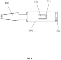
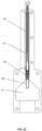
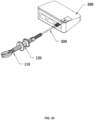
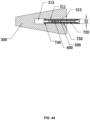
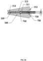
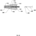
- the delivery device 12 may include a handle 110, a sliding portion 120, the sheath 200, and a shaft 210.
- the shaft 210 may be arranged in a channel of the sheath 200.
- a proximal end of the shaft 210 may be connected to the sliding portion 120.
- a proximal end of the sheath 200 may be connected to the handle 110.
- the sliding portion 120 may slide on the handle 110 to drive the shaft 210 to move towards the proximal end or the distal end.
- the handle 110, the sliding portion 120, and the shaft 210 may constitute an operation portion of the delivery device 12.
- the sheath 200 and an internal space of the sheath 200 may form the delivery pipe of the delivery device.
- a releasable connection between the end effector device 11 and the delivery device 12 may be performed by the operation portion.
- one end of the shaft 210 may extend into or retract from the accommodation portion, and another end of the shaft 210 may be connected to the sliding portion 120.
- An end on the shaft 210 for connecting the sliding portion 120 may become a proximal end of the shaft 210, and another end without connecting the sliding portion 120 may become the distal end of the shaft 210.
- the distal end of the shaft 210 may include a connecting end 211.
- the limiting convex 520 When the distal end of the shaft 210 extends into the accommodation portion, due to the elasticity of the limiting convex 520, the limiting convex 520 may be subjected to a compressing force applied by the connecting end 211 towards the limiting concave 202, so that the limiting convex 520 may be compressed by the connecting end 211 and extend into the limiting concave 202.
- An outer diameter of the connecting end 211 may be greater than an inner diameter of the limiting convex 520.
- the inner diameter of the limiting convex 520 may be an inner diameter of the inner pipe 502 or an inner diameter of the elastic ring.
- the limiting convex 520 When the distal end of the shaft 210 retracts from the accommodation portion, the limiting convex 520 may be relieved from being compressed by the connecting end 211, such that the limiting convex 520 may be elastically restored, and then retract from the limiting concave 202. In some embodiments, the distal end of the shaft 210 may omit the connecting end 211. The outer diameter of the shaft 210 may be greater than the inner diameter of the limiting convex 520. After the shaft 210 extends into the limiting convex 520, the limiting convex 520 may be directly compressed to extend the limiting convex 520 into the limiting concave 202.
- the connecting end 211 may be integrally formed with the shaft 210.
- the connecting end 211 may be machined at one end of the shaft 210.
- the connecting end 211 may be detachably connected to the shaft 210.
- a threaded hole may be positioned along one axial direction of the connecting end 211 or the shaft 210, and an external thread corresponding to the threaded hole may be positioned along another axial direction of the connecting end 211 or the shaft 210.
- the connecting end 211 and the shaft 210 may be detachably connected through a thread.
- the connecting end 211 and the shaft 210 may be detachably connected by a magnetic connection.
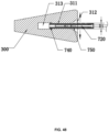
- the distal end of the shaft 210 may be configured with the connecting end 211.
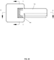
- the distal end of the sheath 200 may be configured with an end cover 201.
- An inner wall of the end cover 201 may be configured with the limiting concave 202.
- the limiting concave 202 may be configured to cooperate with the limiting convex 520 to complete the connection and release of the sheath 200 and the inner pipe 502. When the sheath 200 may fit snugly over the limiting convex 520.
- the connecting end 211 may extend into or retract from the inner pipe 502. When the connecting end 211 extends into the inner pipe 502, the limiting convex 520 may be compressed by the connecting end 211 and extend into the limiting concave 202.
- the inner pipe 502 and the sheath 200 may be connected to push the sheath 200 to the distal end.
- the accommodation pipe 500 may also be pushed to the distal end. If the sheath 200 pulls to the proximal end, the accommodation pipe 500 may also be brought to the proximal end.
- the connecting end 211 retracts from the inner pipe 502
- the limiting convex 520 may retract from the limiting concave 202.
- a connection between the accommodation pipe 500 and the sheath 200 may be released. For example, after the clip 400 is ligated, the sheath 200 may be taken out separately and the clip 400 may be left at the lesion to remain ligated.
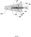
- a proximal end of the first clip arm 410 may be configured with a first bending portion 411 bending towards the second clip arm 420.
- the first bending portion 411 may be configured with a first hole 412.
- a proximal end of the second clip arm 420 may be configured with a second bending portion 421 bending towards the first clip arm 410.
- the second bending portion 421 may be configured with a second hole 422.
- a bending angle between the first bending portion 411 and the first clip arm 410 may be 85° ⁇ 95°.
- a bending angle between the second bending portion 421 and the second clip arm 420 may be 85° ⁇ 95°.
- a sum of the bending angles of the first bending portion 411 and the second bending portion 421 may be 180°.
- the first hole 412 and the second hole 422 may at least partially overlap and communicate, and the overlapping and communicating part of the first hole 412 and the second hole 422 may form a connecting hole 432.
- the "at least partially overlapping" may include a partially overlapping communication and a completely overlapping communication.
- the partially overlapping communication may refer to that the first hole 412 and the second hole 422 are slightly staggered without complete overlapping.
- the completely overlapping communication may refer to that the first hole 412 completely overlaps the range of the second hole 422, or the second hole 422 completely overlaps the range of the first hole 412.
- the overlapping may be understood as two holes connected to each other. After the first hole 412 and the second hole 422 are connected, the connection part between the first hole 412 and the second hole 422 may form the connecting hole 432.
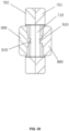
- the shaft 210 may fit snugly over the connecting hole 432.
- the shaft 210 may include a large-diameter portion 212 and a small-diameter portion 213.
- a diameter of the large-diameter portion 212 of the shaft 210 may be larger than an inner diameter of the connecting hole 432.
- a diameter of the small-diameter portion 213 may be smaller than the inner diameter of the connecting hole 432.
- the small-diameter portion 213 may be fixedly connected to the distal end of the shaft 210, and the large-diameter portion 212 may be fixedly connected to the small-diameter portion 213.
- the distal end of the shaft 210 may be fixedly connected to the connecting end 211.
- a distal end of the connecting end 211 may be fixedly connected to the small-diameter portion 213.
- a distal end of the small-diameter portion 213 may be fixedly connected to the large-diameter portion 212.
- the large-diameter portion 212 and the small-diameter portion 213 of the shaft 210 may be integrally formed, or the large-diameter portion 212 of the shaft 210 may be fixedly connected to the small-diameter portion 213 by gluing, a fastener, welding, etc.
- the connection between the effector portion and the operation portion may be completed, so that the effector portion may be controlled by the operation portion to perform the specified operation, such as ligation operation, etc.
- the large-diameter portion 212 of the shaft 210 may enter into the connecting hole 432, since the diameter of the large-diameter portion 212 may be larger than the inner diameter of the connecting hole 432, the large-diameter portion 212 may press the connecting hole 432 to increase the inner diameter of the connecting hole 432. At this time, the elastic ring may be pressed and have the elastic force to make the large-diameter portion 212 traverse.
- the first clip arm 410 and the second clip arm 420 may be away from each other through the elastic force of the elastic ring, so that the first hole 412 and the second hole 422 may be staggered with each other, thereby reducing the inner diameter of the connecting hole 432, so that the large-diameter portion 212 may not move to the proximal end through the connecting hole 432 without an external force.
- the distal end of the shaft 210 may be configured with the large-diameter portion 212 and the small-diameter portion 213.
- the large-diameter portion 212 may be positioned at the distal end of the small-diameter portion 213.
- the small-diameter portion 213 may be positioned at the distal end of the connecting end 211.
- the diameter of the large-diameter portion 212 may be larger than the diameter of the small-diameter portion 213.
- the distal end of the connecting end 211 may be configured with the large-diameter portion 212 and the small-diameter portion 213.
- the small-diameter portion 213 may be positioned between the large-diameter portion 212 and the connecting end 211.
- the diameter of the large-diameter portion 212 may be larger than the diameter of the small-diameter portion 213.
- the diameter of the small-diameter portion 213 may be the same as or different from the diameter of the connecting end 211.
- the small-diameter portion 213 may be a part of the distal end of the connecting end 211.
- the connecting portion between the first hole 412 and the second hole 422 of the clip 400 may form the connecting hole 432.
- the large-diameter portion 212 may need to traverse the first hole 412 and the second hole 422 to complete the connection.
- the elastic force of the elastic ring 402 may tend to keep the first clip arm 410 and the second clip arm 420 away from each other, so that the first hole 412 and the second hole 422 may tend to be staggered with each other and the diameter of the connecting hole 432 may tend to be reduced.
- the effector portion may move in the accommodation portion under the operation of the operation portion.
- the operator may push the sliding portion 120 to the distal end to move the clip 400 to the distal end under a drive of the shaft 210.
- the operator may also push the sliding portion 120 towards the proximal end to move the clip 400 towards the proximal end under a drive by the shaft 210.
- a distal end of the outer pipe 501 may be configured with a blocking portion 513.
- the blocking portion 513 may extend into the channel of the accommodation pipe 500.
- the blocking portion 513 may be positioned at a distal end of the connecting pin 601. Due to the blocking of the blocking portion 513, the clip 400 may be prevented from retracting from the distal end of the accommodation pipe 500.
- the assembly of the end effector device 11 and the delivery device 12 may be performed manually by the operator.
- the end effector instrument 10 in order to replace the manual operation of the operator and improve the assembly efficiency and accuracy of the end effector device 11 and the delivery device 12, the end effector instrument 10 may also include an assembly device 13 configured to assembly the end effector device 11 and the delivery device 12 to complete the connection between the end effector device 11 and the delivery device 12.
- the assembly device 13 may also be referred to as an assembly system.
- the assembly device 13 may include an assembly box 700 configured to fix the end effector device 11 and the delivery device 12 when the end effector device 11 and the delivery device 12 are assembled.
- the assembly box 700 may include a chamber for accommodating the end effector device 11 and the delivery device 112. During the assembly, the assembly box 700 may fix positions of the end effector device 11 and the delivery device 12 through the chamber so that the end effector device 11 and the delivery device 12 may not move relative to each other.
- the embodiment may also include the assembly box 700 configured to assemble the end effector device 11 with the delivery device 12.
- the assembly box 700 may include the connection between the sheath 200 and the accommodation pipe 500 and the connection between the shaft 210 and the clip 400.
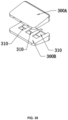
- the assembly box 700 may include a housing.
- the housing may be configured with an effector device chamber 710 and an assembly groove 720 that are axially communicated.
- the housing may include a first-half box 701 and a second-half box 702.
- the first-half box 701 and the second-half box 702 may form the effector device chamber 710 and the assembly groove 720.
- the assembly groove 720 may be configured to place the delivery device 12.
- the effector device chamber 710 may be configured to place the end effector device 11.
- the end effector device 11 may be sterilized and sealed in the assembly box 700 when the end effector device 11 leaves the factory to ensure the cleanliness of the end effector device 11.
- the assembly box 700 may be configured with the assembly groove 720.
- the assembly groove 720 may be configured with a groove slot 722.
- the sheath 200 may be put into the assembly groove 720 through the groove slot 722, which may be convenient for operation.
- the groove slot 722 of the assembly groove 720 may be positioned on a plane where the clip 400 opens.
- a proximal end of the assembly groove 720 may be configured with a limiting slot 721.
- the limiting slot 721 may be connected to the groove slot 722.
- a width of the limiting slot 721 may be smaller than a width of the assembly groove 720.
- the sheath 200 may be clamped into the limiting slot 721.
- the width of the limiting slot 721 may be by way of interference fit with the sheath 200.
- the sheath 200 may be not easy to retract from the limiting slot 721, which may be convenient for positioning the sheath 200 to complete the assembly more easily.
- the effector device chamber 710 may be configured with an assembly convex 730.
- the assembly convex 730 may be configured to abut the accommodation pipe 500.
- the accommodation pipe 500 may abut the assembly convex 730.
- the sheath 200 may be put into the assembly groove 720 to push the sheath 200 to move from the proximal end to the distal end, so that the sheath 200 may fit snugly over the inner pipe 502.
- the connecting end 211 of the shaft 210 may be inserted into the channel of the inner pipe 502 to connect the inner pipe 502 to the sheath 200.
- the shaft 210 may be inserted into the connecting hole 432 to connect the shaft 210 to the clip 400.
- the assembly convex 730 may abut the accommodation pipe 500, when the sheath 200 or the shaft 210 moves from the proximal end to the distal end, the movement of the accommodation pipe 500 to the distal end may be bulged, which may be convenient for assembly.
- the assembly process of assembling the end effector device 11 and the delivery device 12 using the assembly box 700 may be as follows:
- the end effector device 11 may be pre-installed in the effector device chamber 710.
- a distal end of the outer pipe 501 of the clip 400 may abut the assembly convex.
- the clip 400 may be in an open state, and the clip 400 may not retract from the effector device chamber 710;
- the delivery device 12 may be put into the assembly groove 720 from the groove slot 722 on a side.
- the distal end of the sheath 200 may abut the proximal end of the accommodation pipe 500.
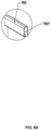
- the proximal end of the sheath 200 may be inserted into the limiting slot 721 as shown in FIGs. 16 and 17 .
- the end cover 201 of the sheath 200 may fit snugly over the inner pipe 502.
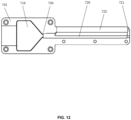
- a cross-section of the limiting slot 721 may be shown in FIG. 12 .
- An area of the cross-section of the limiting slot 721 may gradually decrease along a direction from the groove slot 722 of the assembly groove 720 to a bottom of the assembly groove 720.
- the sheath 200 may be gradually clamped by the limiting slot 721.
- the cross-section of the limiting slot 721 may be shown in FIG. 13 .
- the area of the cross-section of the limiting slot 721 may successively include a narrow section and a wide section from the direction from the groove slot 722 of the assembly groove to the bottom of the assembly groove 720.
- a width L1 of the narrow section may be smaller than a width L2 of the wide section.
- the sheath 200 may traverse the narrow section and be stuck between the narrow section and the wide section.
- the connecting end 211 may be inserted into the channel of the inner pipe 502 and the large-diameter portion 212 may traverse the connecting hole 432.
- the limit convex 520 may be compressed by the connecting end 211 and extend into the limiting concave 202.
- the inner pipe 502 and the sheath 200 may be connected to each other to push the sheath 200 to move to the distal end, and the accommodation pipe 500 may also be pushed to the distal end.
- the sheath 200 may be pulled to move to the proximal end, and the accommodation pipe 500 may also be moved to the proximal end.
- the connecting hole 432 may be stuck in the small-diameter portion 213.
- the clip 400 may be connected to the shaft 210.
- the movement of the shaft 210 may drive the clip 400 to move together.
- the clip 400 and the shaft 210 may be connected, and the sheath 200 and the accommodation pipe 500 may be connected.
- the clip 400 may be driven to move towards the proximal end.
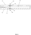
- the clip 400 may be compressed and closed by the accommodation pipe 500. After the clip 400 is closed, the clip 400 may be taken out of the effector device chamber 710 as shown in FIG. 21 .
- the assembled end effector instrument 10 may be used for surgery such as ligation.
- the end effector instrument 10 may be transported to a lesion under an endoscope, and a human tissue 800 may be grabbed to prepare for the ligation.
- the clip 400 may also move towards the proximal end.
- the clip 400 may be gradually closed for the ligation.
- the locking convex 602 may press the locking portion 511 outward.
- the elastic piece 510 may deform to make the locking portion 511 bulge the locking convex 602 outward and move the locking convex 602 to the proximal end of the locking portion 511 through the locking portion 511.
- the clip 400 may be closed and the locking portion 511 may be positioned at the distal end of the locking convex 602.
- the locking portion 511 may rebound.
- the locking portion 511 may extend into the accommodation pipe 500.
- the locking portion 511 may be positioned on a path of the locking convex 602 moving towards the distal end to prevent the locking convex 602 from moving to the distal end.
- the clip 400 may be locked by the locking convex 602 and the locking portion 511.
- the clip 400 may not move to the distal end of the accommodation pipe 500 to avoid reopening after the clip 400 is closed to ensure the stability of the ligation.
- the connecting end 211 may retract from the channel of the inner pipe 502, and the connection between the sheath 200 and the inner pipe 502 may be released.
- the large-diameter portion 212 may retract from the connecting hole 432, and the connection relationship between the shaft 210 and the clip 400 may be released.
- the connection between the delivery device 12 and the end effector device 11 may be released.
- the delivery device 12 may be taken out and the end effector device 11 may be left and in the ligated state.
- the end effector device 11 may include an expanding window 550 for providing an operation space for an opening operation of the first clip arm 410 and the second clip arm 420 on the accommodation portion.
- the assembly box 700 may include an operation window 705 for providing the operation space for the opening operation on the assembly box 700.
- the operation window 705 may be connected to the expanding window 550.
- the expanding portion may extend into an interior of the end effector device 11 through the operation window 705 and the expanding window 550, facilitating the connection between the end effector device 11 and the delivery device 12.
- a side wall of the accommodation pipe 500 may be configured with the expanding window 550.
- the expanding window 550 may be connected to the channel of the accommodation pipe 500.
- the first clip arm 410 and the second clip arm 420 may be opened by the expanding window 550, so that the diameter of the connecting hole 432 may increase, which may facilitate the insertion of the large-diameter portion 212 of the shaft 210.
- the outer pipe 501 may be configured with the expanding window 550.
- the inner pipe 502 may be configured with the expanding window 550, or both the inner pipe 502 and the outer pipe 501 may be respectively configured with the expanding window 550 that may communicate with each other.
- the housing may also be configured with the operation window 705.
- the operation window 705 may be connected to the effector device chamber 710.
- both the first-half box 701 and the second-half box 702 may be configured with the operation window 705, respectively.
- the diameter of the connecting hole 432 may be maintained by opening the first clip arm 410 and the second clip arm 420 through the operation portion, so that the distal end of the shaft 210 may be inserted into the connecting hole 432 to complete the connection between the shaft 210 and the clip 400.
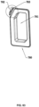
- the assembly box 700 may also include an expanding portion 900.
- the expanding portion 900 may extend into the effector device chamber 710 through the operation window 705.
- the assembly box 700 may be configured with the expanding portion 900 to facilitate the expansion of the connecting hole 432.
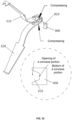
- a head portion of the expanding portion 900 may be configured with a concave portion 910.
- the width of the concave portion 910 may gradually decrease from an opening of the concave portion 910 to a bottom of the concave portion 910.
- An inner wall of the concave portion 910 may form a compressing surface.
- the first clip arm 410 and the second clip arm 420 may be pressed and close to each other by the inner wall of the concave portion 910.
- An overlapping area of the first hole 412 and the second hole 422 may increase, i.e., the diameter of the connecting hole 432 may increase, which may facilitate the insertion of the large-diameter portion 212.
- the assembly box 700 when the assembly box 700 is configured to assemble the end effector device 11 and the delivery device 12 by the operator, the operator may need to manually press the assembly box 700 or manually operate the expanding portion 900 to perform the assembly operation.
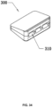
- the assembly device 13 may include the assembly box 700 and an assembly tool 300. The assembly tool 300 may press the assembly box 700 instead of the operator.
- the end effector instrument 10 may include the end effector device 11 and the delivery device 12.
- the delivery device 12 may include the operation portion (the handle 110, the sliding portion 120, and the shaft 210) and the delivery pipe (the sheath 200).
- the end effector device 11 may include an effector portion (the clip 400), an accommodation portion (the accommodation pipe 500), and a connecting device connecting the effector portion and the accommodation portion (not shown in the figure).
- the assembly system may include the assembly tool 300 and the assembly box 700 for assembling the end effector device 11 and the delivery device 12 to form the end effector instrument 10.
- the assembly box 700 may include the accommodation portion, the assembly groove 720, and a joint portion 750.
- the accommodation portion may be configured to accommodate the end effector device 11.
- the assembly groove 720 may be configured to accommodate the delivery device 12 to complete the assembly of the delivery device 12 and the end effector device 11.
- the joint portion 750 may be configured to fix the delivery device 12 in the assembly groove 720.
- the accommodation portion may also be referred to as the effector device chamber 710 as described above.
- the end effector device 11 may be accommodated in the effector device chamber 710 of the assembly box 700.
- the delivery device 12 may enter into the assembly box 700 through the assembly groove 720 to complete the assembly process with the assistance of the assembly tool 300.
- the whole assembly process may include but be not limited to two assembly processes: a first assembly that is the assembly of the sheath 200 and the accommodation pipe 500, and a second assembly that is the assembly of the shaft 210 and the clip 400.
- the joint portion 750 may include a first portion 752 and a second portion 753.
- the first portion may extend beyond an outer surface of the assembly groove.
- the second portion 753 may enter into an interior of the assembly groove 720, thereby compressing a delivery pipe (the sheath) of the delivery device 12 positioned in the assembly groove 720 and limiting the axial movement of the delivery pipe relative to the assembly groove 720.
- the joint portion 750 may include a wave-shaped structure, a wall-shaped structure, a tooth-shaped structure, or the like.
- the application of a compressing force to the first portion 752 may be performed by manual hand pressing.
- the press of the first portion may be accomplished by an assembly tool as described elsewhere in the present disclosure.
- the joint portion 750 may be a wave-shaped structure.
- the convex portion relative to the assembly groove 720 may be the first portion 752, and the concave portion relative to the assembly groove may be the second portion 753.
- the joint portion 750 may include a plurality of convexes 751 as shown in FIG. 43 , i.e., a part of the plurality of convexes 751 in a same direction may be used as the first portion, and the other part in a direction may be used as the second portion.
- the assembly box 700 may include the first-half box 701 and the second-half box 702. When the first-half box 701 and the second-half box 702 are separated, the end effector device 11 may be mounted in one of the first-half box 701 and the second-half box 702. When the first-half box 701 and the second-half box 702 are combined, the end effector device 11 may be mounted in the assembly box 700.
- the assembly box 700 may be configured with the assembly groove 720 extending from the distal end to the proximal end.
- An exterior portion of the first-half box 701 and/or the second-half box 702 may be configured with the joint portion 750.
- the joint portion 750 may be elastic.
- the joint portion 750 may be arranged along a peripheral surface of the assembly groove 720.
- the first portion 752 of the joint portion 750 may be formed by a plurality of convexes 751 or a single convex 751.
- the joint portion 750 formed by the plurality of convexes 751 may have a large stress area, facilitating a stable stress and easily contacting with the sheath 200 in the assembly groove 720.
- the joint portion 750 may be elastic.
- the height of the joint portion 750 may be D1 without force.
- the assembly device 13 may also include the assembly tool 300.
- the assembly tool 300 may include at least one groove 310.
- the assembly box 700 may enter into or retract from the at least one groove 310. When the assembly box 700 enters into the at least one groove 310, the end effector device 11 and the delivery device 12 may be assembled. More descriptions of the assembly process may be found elsewhere in the present disclosure.
- the assembly box 700 may drive the assembled end effector device 11 and delivery device 12 to retract from the groove 310.
- the assembled end effector device 11 and delivery device 12 may be used only by removing the assembly box 700.
- the assembly tool 300 may include a plurality of grooves 310. The plurality of grooves 300 may correspond to a plurality of assembly boxes 700. In this way, one assembly tool 300 may complete the assembly of a plurality of groups of the effector portion of the end effector device 11 and a shaft of an output device, thereby increasing the assembly efficiency.
- the assembly tool 300 may at least include a groove 310.
- the assembly tool 300 in FIG. 35 may include three grooves 310. Each of the three grooves 310 may separately accommodate the assembly box 700 to facilitate the assembly process.
- the assembly tool 300 may include a first assembly housing 300A and a second assembly housing 300B.
- the first assembly housing 300A and the second assembly housing 300B may be assembled from an upper housing and a lower housing, or a left housing and a right housing, or formed as a whole, which may only need to meet the requirements that the groove 310 in the housing meets the dimension and structure.
- the groove 310 may include a first channel 311.
- a height of the first channel 311 may be smaller than or equal to a height of the joint portion 750.
- the first channel 311 may compress the first portion 752.
- a height of a channel may represent a distance between an upper surface and a lower surface of the channel.
- the joint portion 750 may be elastic and deform under the compressing of the first channel 311.
- the groove 310 may also include a second channel 312.
- the second channel 312 may be connected to the first channel 311.
- a distal end of the second channel 312 may be connected to a proximal end of the first channel 311.
- a height of the second channel 312 may gradually decrease along a direction from the proximal end to the distal end. It may be understood that, as shown in FIG. 44 , a proximal end may represent an end closer to the operator when the operator operates the assembly box 700 into the groove 310; and an end farther away from the operator may be a distal end.
- a proximal end of the channel may be an entrance end of the channel, and a distal end of the channel may be an exit end of the channel.
- the height of the first channel 311 may be equal to or smaller than a minimum height of the second channel 312.
- the height of the second channel 312 at the proximal end may be a maximum height, which may be greater than the height of the joint portion 750, so that the joint portion 750 may enter into the second channel 312 and the first channel 311 and be compressed by the first channel 311.
- the groove 310 may also include a third channel 313.
- the third channel 313 may be connected to the first channel 311, and the third channel 313 may be arranged at the distal end of the first channel 311.
- a minimum height of the third channel 313 may be greater than the maximum height of the first channel 311.
- the groove 310 of the assembly box 700 may extend from the proximal end to the distal end along an axis.
- the second channel 312, the first channel 311, and the third channel 313 may be respectively configured from the proximal end to the distal end.
- the height of the second channel 312 may gradually decrease from the proximal end to the distal end.
- a height of the third channel 313 may be greater than the height of the first channel 311.
- an exterior portion of the assembly box 700 may be configured with a convex portion 740.
- the convex portion 740 may be elastic. When the assembly box 700 enters into the first channel 311, the first channel 311 may compress the convex portion 740. The convex portion 740 may be elastically deformed to make the convex portion 740 in a compressed state, so that the assembly box 700 may traverse the first channel 311. When the assembly box 700 enters into the third channel 313, the convex portion 740 may be relieved from being compressed, the convex portion 740 may be restored to an original state due to elastic deformation. In some embodiments, the convex portion 740 may provide feedback information to the operator.
- the feedback information may be a change in the compressing force of the groove 310 on the convex portion 740.
- the second channel 312 may not compress the convex portion 740.
- the convex portion 740 may be compressed.
- the operator may sense a sharp increase of the compressing force on the convex portion 740 to know that the assembly box 700 has entered into the first channel 311 from the distal end of the second channel 312.
- the operator senses that the compressing force on the convex portion 740 decreases sharply, it may be known that the convex portion 740 may be relieved from being compressed by the first channel 311 and enter into the third channel 313.
- a farthest end of the first-half box 701 and/or the second-half box 702 may be configured with a first groove 741 and a second groove 742.
- the first groove 741 and the second groove 742 may be hollow grooves arranged on an outer housing of the first-half box 701 and/or the second-half box 702, respectively.
- the convex portion 740 may be a convex portion arranged between the first groove 741 and the second groove 742.
- the convex portion 740 may be elastic.
- the joint portion 750 When the joint portion 750 is pressed from outside to inside, a part of the joint portion 750 may enter into the assembly groove 720. If the assembly groove 720 is configured with the sheath 200 at this time, the joint portion 750 may compress the sheath 200 so that the sheath 200 and the assembly groove 720 may be axially fixed; conversely, when the compressing force of the joint portion 750 from outside to inside disappears, the joint portion 750 may be elastically restored and retract from the channel of the assembly groove 720. The sheath 200 may move axially in the assembly groove 720.
- the first channel 311 may be elastic. When the joint portion 750 is positioned within the first channel 311, the height of the first channel 311 may increase. After the joint portion 750 enters into the first channel, the first channel 311 may be expanded. At the same time, the first channel 311 may exert a reaction force from outside to inside on the joint portion 750. The joint portion 750 may compress the sheath 200 positioned in the assembly groove 720 to fix the sheath 200 by a compressing force with a controllable direction and magnitude.
- the assembly of the end effector device 11 and the delivery device 12 using the assembly box 700 and the assembly tool 300 may include the following assembly process.
- the effector device chamber 710 of the assembly box 700 may accommodate the end effector device 11 (the clip 400 and the accommodation pipe 500).
- the joint portion 750 arranged outside the assembly groove 720 may be elastic. At this time, the joint portion 750 may be subjected to no force.
- the height of the joint portion 750 may be D1.
- the assembly box 700 may be pushed from the proximal end to the distal end into the groove 310 of the assembly tool 300.
- the convex portion 740 arranged at the farthest end of the assembly box 300 may enter into the second channel 312.
- the height of the second channel 312 may gradually decrease from the proximal end to the distal end, forming a suitable guiding surface to guide the convex portion 740 into the first channel 311.
- the convex portion 740 arranged at the farthest end of the assembly box 300 may enter into the first channel 311.
- the convex portion 740 may shrink inward under a compressing force from the groove. Since the height of the first channel 311 is H (as shown in FIG.
- the height of the convex portion 740 may be equal to the height H of the first channel 311.
- the convex portion 740 arranged at the farthest end of the assembly box 300 may enter into the third channel 313. Since the height of the third channel 313 is larger than the height of the first channel 311, the compressing force from the groove in the third channel 313 may decrease relative to that in the first channel 311. Since the height of the third channel 313 is C, the height of the convex portion 740 in the third channel 313 may be equal to the height C of the third channel 313. Since C > H , the height of the convex portion 740 in the third channel 313 may be greater than that of the convex portion 740 in the first channel 311.
- the first feedback information may indicate that the joint portion 750 may be positioned at the distal end of the second channel 312 and about to enter into the first channel 311.
- the first feedback information may signify the operator if the assembly box continues to move from the proximal end to the distal end when the first feedback information is generated, the joint portion 750 may enter into the first channel 311.
- the first feedback information may be set to signify the operator to stop pushing the assembly box 700 into the groove 310 from the distal end to the proximal end and to complete a first assembly process instead.
- the first assembly may refer to an assembly process of combining the delivery portion of the delivery device 12 with the accommodation portion of the end effector device 11. In some embodiments, the first assembly may include the followings.
- the assembly box 700 may be partially accommodated in the groove 310 of the assembly tool 300. At this time, the assembly box 700 may be temporarily fixed in the groove 310.
- the sheath 200 of the delivery device 12 may approach the assembly box 700 from the proximal end to the distal end.
- the sheath 200 may enter into the assembly groove 720 and continue to push the sheath 200 from the proximal end to the distal end until the distal end of the sheath 200 of the delivery device 12 is combined with the proximal end of the accommodation pipe 500 of the end effector device 11, thus completing the first assembly process of the sheath 200 and the accommodation pipe 500.
- the second assembly may refer to an assembly process of establishing a connection between the delivery device 12 and the end effector device 11. In some embodiments, the second assembly may include the followings.
- the sheath 200 and the assembly box 700 may be continuously pushed into the groove 310 from the proximal end to the distal end at the same time.
- the convex portion 740 may enter into the third channel 313.
- the joint portion 750 may enter into the first channel 311.
- the joint portion 750 may be compressed from outside to inside in the first channel.
- the height of the joint portion 750 may be reduced from D1 to D2 (the height of the joint portion 750 positioned outside the first channel 311 may be D1 ; the height of the joint portion 750 positioned inside the first channel 311 may be D2 ) .
- the joint portion 750 may be elastically deformed to compress the sheath 200 positioned in the assembly groove 720.
- the sheath 200 may be axially fixed with respect to the assembly box 700. As shown in FIG. 47 , at this time, the shaft 210 may traverse the channel of the sheath 200 from the proximal end to the distal end to approach the clip 400. The sliding portion 120 may be pushed from the proximal end to the distal end until the distal end of the shaft 210 of the delivery device 12 is combined with a proximal end of the clip 400 of the end effector device 11, thus completing the second assembly process of the shaft 210 and the clip 400.
- the first assembly of the sheath 200 of the delivery device 12 and the accommodation pipe 500 of the end effector device 11 may be completed.
- the second assembly of the shaft 210 of the delivery device 12 and the clip 400 of the end effector device 11 may be completed. Therefore, the end effector device 11 and the delivery device 12 may be completely assembled into the end effector instrument 10 to form a whole.
- the assembly box 700 may be pushed from the distal end to the proximal end.
- the assembly box 700 may be pushed out from the distal end to the proximal end along the groove 310.
- the convex portion 740 When the convex portion 740 is about to traverse the third channel 313 and enter into the first channel 311, the convex portion 740 may suddenly change (becoming larger) due to the compressing force.
- the second feedback information may be generated.
- the second feedback information may indicate that the joint portion 750 may have just been extracted from the first channel 311 and be positioned outside the first channel 311.
- the joint portion 750 may be positioned outside the first channel 311. A compressing force subjected to the joint portion 750 from outside to inside may disappear, the joint portion 750 may be elastically restored. The joint portion 750 may retract from the assembly groove 720. A compressing force of the joint portion 750 on the sheath 200 from outside to inside may disappear. The sheath 200 may restore free axial movement in the assembly groove 720. As shown in FIG. 49 , the end effector instrument 10 (the end effector device 11 and the delivery device 12) may be pushed from the distal end to the proximal end. The end effector instrument 10 may retract from the assembly groove 720 of the assembly box 700.
- the above assembly operations may include but be not limited to the first assembly and the second assembly, and a portion thereof may be adjusted.
- the first assembly may be completed first and then the assembly box may be fixed.
- the assembly box 700 may be fixed with the assembly tool 300, and then the second assembly may be completed.
- the third channel 313 may be configured with an elastic component 320.
- the elastic component 320 may provide a bias pressure to the assembly box 700 along a first direction X (see FIG. 51 ), so that the assembly box 700 may retract from the third channel 313.
- a bias force may be an elastic force generated by the elastic component when the assembly box 700 contacts the elastic component 320.
- the first direction X of the bias force may be the same as a direction along which the assembly box 700 may retract from the third channel 313.
- the first direction X may be understood as an axial direction from the distal end to the proximal end in the third channel.
- the elastic component 320 may provide feedback information for the operator.
- the feedback information may include that a normal force from the distal end to the proximal end may be generated for the contact between the convex portion 740 and the proximal end of the elastic component 320.
- the feedback information provided by the elastic component 320 may signify the operator that the assembly box 700 may enter into the third channel 313 or a certain position in the third channel 313. For example, the greater the normal force felt by the operator, the further a distance that the assembly box 700 may enter into the third channel 313.
- the assembly tool 300 may also include a fourth channel 314. One end of the elastic component 320 may be fixedly arranged in the fourth channel 314.
- the fourth channel 314 may be connected to the first channel 311, the second channel 312, and the third channel 313.
- the fourth channel 314 may be arranged at a distal end of the third channel 313, and another end of the elastic component 320 may extend from the distal end to the proximal end into an interior of the third channel 313.
- the assembly tool may omit the fourth channel.
- One end of the elastic component 320 may be directly fixed to the distal end of the third channel 313, and another end may extend into the interior of the third channel 313.
- the elastic component may be a spring.
- the groove 310 of the assembly tool 300 may also be configured with the fourth channel 314.
- the fourth channel 314 may be connected to the first channel 311, the second channel 312, and the third channel 313.
- the fourth channel may be arranged at the distal end of the third channel.
- the elastic component 320 may be fixedly arranged in the third channel.
- the elastic component 320 may extend from the distal end to the proximal end as shown in FIG. 50 .
- a difference in the assembly process of an assembly system configured with the elastic component 320 may include that the processes of fixing the assembly box, the first assembly, the second assembly, and the retraction of the end effector instrument 10 from the assembly box may be different, which are described in detail below.
- the convex portion 740 may suddenly change (or decrease) due to a compressing force, and first feedback information may be provided.
- the convex portion 740 may abut the proximal end of the elastic component 320 to generate a normal force from the distal end to the proximal end, thereby providing third feedback information.
- the first feedback information and the third feedback information may be generated simultaneously or continuously, or only the third feedback information may be generated without the generation of the first feedback information.
- the purpose of the first feedback information and the third feedback information may be to signify the operator to stop pushing the assembly box 700 from the distal end to the proximal end into the groove 310 and to complete the first assembly process instead.
- the first assembly is a first assembly:
- the assembly box 700 may be partially accommodated in the groove 310 of the assembly tool 300. Due to the configuration of the elastic component 320, if the assembly box 700 needs to continue to enter into the groove 310 from the proximal end to the distal end, a pushing force may need to be large enough to overcome the resistance from the elastic force exerted by the elastic component 320. At this time, the assembly box 700 may be temporarily fixed in the groove 310. The sheath 200 of the delivery device 12 may approach the assembly box 700 from the proximal end to the distal end.
- the sheath 200 may enter into the assembly groove 720 and continue to push the sheath 200 from the proximal end to the distal end until the distal end of the sheath 200 of the delivery device 12 is combined with the proximal end of the accommodation pipe 500 of the end effector device 11, thus completing the first assembly process of the sheath 200 and the accommodation pipe 500.
- the second assembly is a first assembly:
- the sheath 200 and the assembly box 700 may be simultaneously pushed from the proximal end to the distal end to enter into the groove 310.
- a pushing force from the proximal end to the distal end may need to be large enough to overcome the resistance from the elastic force exerted by the elastic component 320.
- the elastic component 320 may be compressed.
- the convex portion 740 may enter into the third channel 313 and the joint portion 750 may enter into the first channel 311.
- the joint portion 750 may be pressed from outside to inside in the first channel.
- the height of the joint portion 750 may be reduced from D1 to D2 (the height of the joint portion 750 outside the first channel 311 may be D1 ; the height of the joint portion 750 inside the first channel 311 may be D2 ) .
- the joint portion 750 may be elastically deformed to press the sheath 200 in the assembly groove 720.
- the sheath 200 may be axially fixed relative to the assembly box 700.
- the shaft 210 may traverse the channel of the sheath 200 from the proximal end to the distal end to approach the clip 400.
- the sliding portion 120 may be pushed from the proximal end to the distal end until the distal end of the shaft 210 of the delivery device 12 is combined with the proximal end of the clip 400 of the end effector device 11, thus completing the second assembly process of the shaft 210 and the clip 400.
- the elastic component 320 may be elastically restored to provide fourth feedback information.
- the elastic component 320 may provide a pushing force from the distal end to the proximal end to force the assembly box 700 to move from the distal end to the proximal end.
- the first assembly of the sheath 200 and the accommodation pipe 500 and the second assembly of the shaft 210 and the clip 400 have been completed, i.e., the end effector device 11 and the delivery device 12 have been assembled to form the end effector instrument 10.
- the fourth feedback information may indicate that it is necessary to separate the end effector instrument 10 from the assembly box and the assembly tool.
- the joint portion 750 may be positioned outside the first channel 311. A compressing force subjected to by the joint portion 750 from outside to inside may disappear, and the joint portion 750 may be elastically restored. The joint portion 750 may retract from the assembly groove 720. The compressing force of the joint portion 750 on the sheath 200 may disappear. The sheath 200 may restore free axial movement in the assembly groove 720. As shown in FIG. 55 , the end effector instrument 10 (the end effector device 11 and the delivery device 12) may be pushed from the distal end to the proximal end. The end effector instrument 10 may retract from the assembly groove 720 of the assembly box 700.
- the elastic component 320 may be elastically restored to apply a pushing force to the assembly box 700 from the distal end to the proximal end. If the pushing force is too large, the assembly box 700 may completely retract from the groove 311. At this time, the convex portion 740 positioned at a distal end of the assembly box 700 may become stuck at a step formed due to different heights of the third channel 313 and the first channel 311. A certain normal force from the proximal end to the distal end may be generated. Therefore, by arranging the elastic component 320 and the convex portion 740 at the same time, the assembly box 700 may easily retract from the groove 310, and a speed of the retraction may be safe and controllable.
- the assembly box 700 of the present disclosure may not only be used to fix the end effector device 11 and the delivery device 12 when the end effector device 11 and the delivery device 12 are assembled. In some embodiments, since the end effector device 11 may be installed in the assembly box 700 after factory disinfection, the assembly box 700 may also be configured to package the end effector device 11.
- the assembly box 700 may also include a limiting portion.
- the limiting portion may be configured to limit the relative movement between the delivery device 12 and the assembly box 700.
- the assembly box 700 may include a housing 760.
- the limiting portion may be positioned at the housing 760.
- the delivery device 12 may include the delivery pipe (e.g., the sheath 200).
- the limiting portion may limit the relative movement between the delivery device and the housing 760.
- the limiting portion may include one of a groove body, a limiting channel, or a buckle. For example, a part of the delivery pipe may be clamped in the groove body, the limiting channel, or the buckle.
- At least one convex point may be arranged in the limiting portion.
- a friction between the limiting portion and the delivery pipe may increase, thereby increasing a limiting effect.
- the limiting portion may exclude the at least one convex point.
- a roughness of the surface connected to the delivery pipe may increase to achieve the same effect of the at least one convex point.
- the end effector instrument 10 may include the end effector device 11 and the delivery device 12.
- the delivery device 12 may include the handle 110 and the sheath 200 extending from the distal end to the proximal end.
- a count of the end effector device 11 may be multiple.
- the multiple end effector devices 11 may be sterilized and separately sealed in multiple assembly boxes 700. During surgery operation, the individually sealed assembly boxes 700 may be opened one by one as required, and then the assembly of the delivery device 12 and the end effector device 11 may be completed to assemble the end effector instrument 10.
- the count of the end effector devices 11 and the count of the delivery devices 12 may be matched as required. As shown in FIG. 56 , four end effector devices 11 (the end effector devices 11 may be separately stored in the assembly box 700, and the assembly boxes 700 may be sealedly stored in the housing 760 as shown in FIG. 58 ) and one delivery device 12 (including the handle 110 and the sheath 200) may be selected. The distal end of the delivery device 12 has been assembled with the end effector device 11 to form the end effector instrument 10 before factory packaging.
- the limiting portion may include a plurality of limiting grooves 763.
- the sheath 200 of the delivery device 12 may clamp with the limiting grooves 763.
- the limiting grooves 763 may limit a relative movement between the delivery device 12 and the housing 760 configured with the assembly box 700.
- the housing 760 may include a convex portion 761 and a non-convex portion 762.
- the convex portion 761 may be convex relative to a plane of the non-convex portion 762.
- the accommodation box 700 may be accommodated inside the convex portion 761.
- the convex portion 761 may include a surface of a convex portion 761A and a side surface of a convex portion 761B.
- the limiting groove 763 may be formed by traversing the surface of the convex portion 761A and the side surface of the convex portion 761B.
- a plurality of convex points 764 may be arranged in the limiting groove 763.
- the convex points 764 may increase a friction between the limiting groove 763 and the sheath 200 to make a limiting effect between the limiting groove 763 and the sheath 200 firmer, i.e., to complete the limiting between the delivery device 12 and the assembly box 700.
- the convex portion 760 may include the surface of the convex portion 761A and a plurality of side surfaces of the convex portion 761B.
- the limiting groove 763 traversing the plurality of side surfaces of the convex portion 761B may be formed.
- the housing 760 may include the convex portion 761 and the non-convex portion 762.
- the convex portion 761 may be convex relative to a plane of the non-convex portion 762.
- the accommodation box 700 may be accommodated inside the convex portion 761.
- the limiting portion may be arranged at the non-convex portion 762 and include the plurality of limiting grooves 763.
- the housing 760 may include the convex portion 761 and the non-convex portion 762.
- the convex portion 761 may be convex relative to a plane of the non-convex portion 762.
- the accommodation box 700 may be accommodated inside the convex portion 761.
- the limiting portion may be arranged at the non-convex portion 762.
- the limiting portion may be folded by the non-convex portion 762 to form a limiting channel 763'.
- the limiting portion may also include a buckle 765.
- the buckle 765 may fix the limiting channel 763', so that the limiting channel 763' and the sheath 200 complete a bulking connection, i.e., a limiting between the delivery device 12 and the assembly box 700 may be completed.
- the limiting portion may include the limiting channel 763'.
- a cooperation between the sheath 200 and the limiting channel 763' may be completed by relying on a material elasticity of the non-convex portion 762, i.e., a limiting between the delivery device 12 and the assembly box 700 may be completed.
- the limiting portion may include the limiting channel 763' and a groove 766.
- the non-convex portion 762 may enter into the groove 766, so that a limiting relationship between the limiting channel 763' and the sheath 200 may be firmer, i.e., a limiting between the delivery device 12 and the assembly box 700 may be completed.
- the limiting portion may be a groove body.
- the limiting portion may include a first limiting groove 763A and a second limiting groove 763B.
- the end effector instrument 10 may be accommodated in the first limiting groove 763A.
- the assembly box 700 may be accommodated in the second limiting groove 763B.
- the limiting portion may complete a limiting between the delivery device 12 and the assembly box 700.
- FIG. 73 is a flowchart illustrating an assembly and operation method of an end effector instrument according to some embodiments of the present disclosure.
- process 1000 may include the following operations.
- the assembly box 700 may be controlled to enter into the groove 310 of the assembly tool 300.
- the operation 1100 may include the followings.
- the convex portion 740 of the assembly box 700 may be controlled to enter into the first channel 311 from the second channel 312.
- the operator may push the assembly box 700 into the groove 310 of the assembly tool 300 so that the convex portion 740 at the distal end of the assembly box 700 may enter into the first channel 311 from the second channel 312.
- the convex portion 740 may be controlled to enter into the third channel 313 from the first channel 311 and to obtain the first feedback information.
- the convex portion 740 may be compressed by the first channel 311, and a compressing force may be generated and perceived by the operator.
- the convex portion 740 extracts from the first channel 311 and enters into the third channel 313, the convex portion 740 may be relieved from being compressed, and the compressing force may disappear.
- the operator may perceive a sudden change of compressing force and know that the convex portion 740 has entered into the third channel 313. That is, the first feedback information may be the compressing force or a change of the compressing force perceived by the operator.
- the first feedback information may signify the operator of the position of the assembly box 700 in the groove 310.
- the assembly box 700 in response to the first feedback information, the assembly box 700 may be stopped moving.
- the first feedback information may signify the operator that the convex portion 740 of the assembly box 700 has entered into the third channel 313, the assembly box 700 may be stopped pushing.
- the sub-operation 1110, the sub-operation 1120, and the sub-operation 1130 may be only exemplary embodiments of one of the operation methods of operation 1100 and should not be understood as restrictions on operation 1100.
- the operation 1100 may also include other sub-operations.
- the operation 1100 may include the following operations.
- the convex portion 740 of the assembly box 700 may be controlled to enter into the first channel 311 from the second channel 312.
- the convex portion 740 may be controlled to enter into the third channel 313 from the first channel 311.
- the assembly box 700 may be stopped moving.
- the third feedback information may be provided by the elastic component 320 arranged in the third channel 313, i.e., when the operator senses the elastic force provided by the elastic component 320, the operator may know that the convex portion 740 has entered into the third channel 313.
- the delivery pipe of the delivery device 12 may be controlled to enter into the assembly groove and achieve the first assembly with the accommodation portion of the end effector device 11.
- the operator may push the delivery pipe from a proximal end to a distal end to combine the distal end of the delivery pipe with the proximal end of the accommodation portion to complete the first assembly.
- the accommodation portion of the assembly box 700 may enter into a sliding groove of the assembly tool 300.
- the assembly groove 720 and the joint portion 750 of the assembly box 700 may be still outside the assembly tool 300. More descriptions of the first assembly may be found elsewhere in the present disclosure (for example, FIG. 45 and the descriptions thereof), which are not repeated here.
- the assembly box 700 and the delivery pipe may be controlled to continue to move inside the groove 310 so that the delivery pipe may be axially fixed in the assembly groove 720.
- the operator may continue to push the assembly box 700 so that the joint portion of the assembly box 700 and the delivery pipe positioned in the assembly groove may move towards an interior the groove 310 and enter into the first channel 311 after passing through the second channel 312. Since the height of the first channel 311 is smaller than the height of the joint portion and the joint portion may be elastic, the first channel 311 may compress the first portion 752 of the joint portion 750 to allow the second portion 753 of the joint portion to enter into the assembly groove 720. The second portion 753 may compress the delivery pipe, so that the joint portion may clamp the delivery pipe along a radial direction of the delivery pipe to fix the delivery pipe axially in the assembly groove 720. In some embodiments, the operator may manually compress the joint portion 750 to fix the delivery pipe axially in the assembly groove 720.
- the shaft of the delivery device 12 may be controlled to move towards the end effector device 11 to achieve the second assembly with the clip 400.
- the delivery pipe and the accommodation portion may be combined with each other. Axial fixation of the delivery pipe and the assembly groove may be realized.
- the operator may continue to push the shaft in the delivery pipe, so that the connecting end 211 of the shaft 210 may enter into the accommodation portion and compress the limiting convex 520 of the accommodation portion, so that the limiting convex 520 of the accommodation portion may extend into the limiting concave 202 of the delivery pipe to achieve a releasable connection between the delivery pipe and the accommodation portion.
- the shaft 210 may be further pushed, so that the large-diameter portion 212 of the shaft 210 may enter into the connecting hole 432 of the clip 400 to establish the connection between the shaft 210 and the clip 400, i.e., the second assembly. More descriptions of the second assembly may be found elsewhere (for example, FIG.46 and the descriptions thereof) in the present disclosure.
- the assembled end effector device 11 and delivery device 12 may retract from the assembly box 700.
- the operator may pull the assembly box 700 to move from the inside (the distal end) of the groove 310 to the outside (the proximal end) of the groove 310 and obtain the second feedback information.
- the second feedback information may be a normal force felt by the operator when the convex portion 740 becomes stuck at a step formed due to different heights of the third channel 313 and the first channel 311.
- the operator may determine that the joint portion 750 may retract from the first channel 311 based on the second feedback information. At this time, the operator may retract the end effector device 11 and the delivery device 12 from the assembly groove 720.
- the assembly box 700 may abut the elastic component 320. At this time, the assembly box 700 may receive a pushing force applied by the operator from the proximal end to the distal end and an elastic force applied by the elastic component from the distal end to the proximal end, so that the assembly box 700 may not move in the third channel 313.
- the operator may stop pushing the assembly box 700, such that an elastic force generated by the elastic component may be large enough to drive the assembly box 700 to move from the inside (the distal end) of the groove 310 to the outside (the proximal end) of the groove 310.
- the elastic component 320 may provide fourth feedback information to the operator. For example, the operator may feel that the elastic component 320 has lost the elastic force.
- the operator may also directly pull the assembly box 700 out of the groove 310. After that, the operator may directly open the assembly box 700, and then take out the assembled end effector device 11 and the delivery device 12 for usage in surgery.
- the numbers expressing quantities, properties, and so forth, configured to describe and claim certain embodiments of the application are to be understood as being modified in some instances by the term "about,” “approximate,” or “substantially.” For example, “about,” “approximate” or “substantially” may indicate ⁇ 20% variation of the value it describes, unless otherwise stated. Accordingly, in some embodiments, the numerical parameters set forth in the written description and attached claims are approximations that may vary depending upon the desired properties sought to be obtained by a particular embodiment. In some embodiments, the numerical parameters should be construed in light of the number of reported significant digits and by applying ordinary rounding techniques. Notwithstanding that the numerical ranges and parameters setting forth the broad scope of some embodiments of the application are approximations, the numerical values set forth in the specific examples are reported as precisely as practicable.
Landscapes
- Health & Medical Sciences (AREA)
- Surgery (AREA)
- Life Sciences & Earth Sciences (AREA)
- Heart & Thoracic Surgery (AREA)
- Nuclear Medicine, Radiotherapy & Molecular Imaging (AREA)
- Vascular Medicine (AREA)
- Engineering & Computer Science (AREA)
- Biomedical Technology (AREA)
- Reproductive Health (AREA)
- Medical Informatics (AREA)
- Molecular Biology (AREA)
- Animal Behavior & Ethology (AREA)
- General Health & Medical Sciences (AREA)
- Public Health (AREA)
- Veterinary Medicine (AREA)
- Surgical Instruments (AREA)
Claims (14)
- Endeffektorinstrument (10), umfassend:eine Endeffektorvorrichtung (11), wobei die Endeffektorvorrichtung (11) einen Effektorabschnitt umfasst, der zum Durchführen eines spezifizierten Betriebs konfiguriert ist, und einen Aufnahmeabschnitt, der zum teilweisen Aufnehmen des Effektorabschnitts konfiguriert ist, wobei der Aufnahmeabschnitt einen ersten Verbindungsabschnitt umfasst, undeine Abgabevorrichtung (12), die mit der Endeffektorvorrichtung (11) verbunden ist, wobei die Abgabevorrichtung (12) dazu konfiguriert ist, die Endeffektorvorrichtung (11) an eine Zielregion abzugeben, wo der spezifizierte Vorgang durchgeführt werden soll,
die Abgabevorrichtung (12) einen Betriebsabschnitt und ein Abgaberohr beinhaltet, wobei der Betriebsabschnitt dazu konfiguriert ist, den Effektorabschnitt anzutreiben, um den spezifizierten Betrieb durchzuführen, wobei der Betriebsabschnitt einen Schaft beinhaltet,die Abgabevorrichtung einen zweiten Verbindungsabschnitt beinhaltet, wobei der zweite Verbindungsabschnitt an einem distalen Ende des Abgaberohrs positioniert ist,dadurch gekennzeichnet, dassder Aufnahmeabschnitt ein Innenrohr (502) und ein Außenrohr (501) beinhaltet, wobei zumindest ein Abschnitt des Außenrohrs (501) eng über das Innenrohr (502) passt,wenn ein Ende des Schafts in das Innenrohr (502) eintritt, der zweite Verbindungsabschnitt mit dem ersten Verbindungsabschnitt verbunden wird und die Abgabevorrichtung (12) mit der Endeffektorvorrichtung (11) verbunden wird, undwenn sich das Ende des Schafts aus dem Innenrohr (502) zurückzieht, der zweite Verbindungsabschnitt von dem ersten Verbindungsabschnitt getrennt wird und die Abgabevorrichtung (12) von der Endeffektorvorrichtung (11) getrennt wird. - Endeffektorinstrument (10) nach Anspruch 1, wobeider erste Verbindungsabschnitt eine Begrenzungskonvexität (520) beinhaltet,der zweite Verbindungsabschnitt eine Begrenzungskonkavität beinhaltet,wenn der Schaft in das Innenrohr (502) eintritt, die Begrenzungskonvexität (520) elastisch verformt wird, um zu erlauben, dass der zweite Verbindungsabschnitt den ersten Verbindungsabschnitt verbindet, undwenn sich der Schaft aus dem Innenrohr (502) zurückzieht, die Begrenzungskonvexität (520) elastisch wiederhergestellt wird, um zu erlauben, dass sich der zweite Verbindungsabschnitt von dem ersten Verbindungsabschnitt trennt.
- Endeffektorinstrument (10) nach Anspruch 2, wobei die Begrenzungskonvexität (520) und der Aufnahmeabschnitt einstückig gebildet sind.
- Endeffektorinstrument (10) nach Anspruch 1, wobeider Effektorabschnitt einen Verriegelungsverbindungsabschnitt beinhaltet,der Aufnahmeabschnitt einen Verriegelungsabschnitt (511) beinhaltet, wobei der Verriegelungsabschnitt (511) dazu konfiguriert ist, den Verriegelungsabschnitt zu verwenden,wenn der Verriegelungsabschnitt (511) den Verriegelungsverbindungsabschnitt verbindet, der Effektorabschnitt und der Aufnahmeabschnitt relativ zueinander fixiert sind,der Verriegelungsabschnitt (511) auf dem Außenrohr (501) positioniert ist,das Innenrohr (502) eine Führungsnut (503) beinhaltet, die entlang einer axialen Richtung liegt, undder Verriegelungsverbindungsabschnitt dazu konfiguriert ist, in der Führungsnut (503) zu gleiten.
- Endeffektorinstrument (10) nach Anspruch 4, wobei:
der Verriegelungsabschnitt (511) ein elastisches Stück beinhaltet, wobei ein Ende des elastischen Stücks fest mit dem Außenrohr (501) verbunden ist und sich ein anderes Ende des elastischen Stücks in ein Inneres des Innenrohrs (502) erstreckt. - Endeffektorinstrument (10) nach Anspruch 4, wobei:ein dem Effektorabschnitt abgewandtes Ende der Führungsnut (503) eine Positionierungskonvexität (505) aufweist,ein Abstand zwischen der Positionierungskonvexität (505) und dem Effektorabschnitt einen Abstand zwischen dem Verriegelungsabschnitt (511) und dem Effektorabschnitt überschreitet,ein Halteabschnitt auf der Positionierungskonvexität (505) liegt,der Halteabschnitt ein festes Ende und ein freies Ende beinhaltet,das feste Ende des Halteabschnitts fest mit der Positionierungskonvexität (505) verbunden ist, unddas freie Ende des Halteabschnitts einem Inneren der Führungsnut (503) zugewandt ist.
- Endeffektorinstrument (10) nach Anspruch 4, wobei:der Effektorabschnitt einen Clip (400) beinhaltet, wobei der Clip (400) einen ersten Cliparm (410), einen zweiten Cliparm (420) und einen Verbindungsstift (601) umfasst,der erste Cliparm (410) und der zweite Cliparm (420) durch den Verbindungsstift (601) verbunden sind,der Verriegelungsverbindungsabschnitt durch ein Ende oder beide Enden des Verbindungsstifts (601) gebildet wird,ein Ende des ersten Cliparms (410) nahe dem Verbindungsstift (601) einen ersten Biegeabschnitt (412) aufweist, der sich in Richtung des zweiten Cliparms (420) biegt,der erste Biegeabschnitt (412) ein erstes Loch (420) aufweist,ein Ende des zweiten Cliparms (420) nahe dem Verbindungsstift (601) einen zweiten Biegeabschnitt (422) aufweist, der sich in Richtung des ersten Cliparms (410) biegt,der zweite Biegeabschnitt (422) ein zweites Loch (432) aufweist, unddas erste Loch (420) und das zweite Loch (432) einander zumindest teilweise überlappen.
- Endeffektorinstrument (10) nach Anspruch 1, das weiter beinhaltet:
eine Montagevorrichtung (13), die dazu konfiguriert ist, die Endeffektorvorrichtung (11) und die Abgabevorrichtung (12) zusammenzufügen, um eine Verbindung zwischen der Endeffektorvorrichtung (11) und der Abgabevorrichtung (12) herzustellen, wobei
die Montagevorrichtung (13) eine Montagebox (700) beinhaltet, die dazu konfiguriert ist, die Endeffektorvorrichtung (11) und die Abgabevorrichtung (12) zu fixieren, wenn die Endeffektorvorrichtung (11) und die Abgabevorrichtung (12) zusammengefügt sind, wobei die Montagebox (700) beinhaltet:einen Aufnahmeabschnitt, der zum Aufnehmen der Endeffektorvorrichtung (11) konfiguriert ist,eine Montagenut (720), die zum Aufnehmen der Abgabevorrichtung (12) konfiguriert ist, um eine Montage der Abgabevorrichtung (12) und der Endeffektorvorrichtung (11) zu erreichen,einen Gelenkabschnitt (750), der zum Fixieren der Abgabevorrichtung (12) in der Montagenut (720) konfiguriert ist,den Gelenkabschnitt (750), der einen ersten Abschnitt (752) und einen zweiten Abschnitt (753) beinhaltet,den ersten Abschnitt (752) des Gelenkabschnitts (750), der sich über eine Außenfläche der Montagenut (720) hinaus erstreckt, undnachdem der erste Abschnitt (752) des Gelenkabschnitts (750) gedrückt wurde, der zweite Abschnitt (753) des Gelenkabschnitts (750) in ein Inneres der Montagenut (720) eintritt. - Endeffektorinstrument (10) nach Anspruch 8, wobei:die Montagevorrichtung (13) weiter ein Montagewerkzeug (300) beinhaltet,das Montagewerkzeug (300) mindestens eine Nut (310) beinhaltet,die Montagebox (700) dazu konfiguriert ist, in die mindestens eine Nut (310) einzutreten oder sich aus ihr zurückzuziehen,eine der mindestens einen Nut (310) des Montagewerkzeugs (300) einen ersten Kanal (311) beinhaltet,eine Höhe des ersten Kanals (311) kleiner oder gleich einer Höhe des Gelenkabschnitts (750) ist, undwenn der Gelenkabschnitt (750) in den ersten Kanal (311) eintritt, der erste Kanal (311) auf den ersten Abschnitt (752) des Gelenkabschnitts (750) drückt.
- Endeffektorinstrument (10) nach Anspruch 9, wobei:die Nut (310) weiter einen zweiten Kanal (312) beinhaltet,der zweite Kanal (312) mit dem ersten Kanal (311) in Verbindung steht,der zweite Kanal (312) an einem Eingangsende des ersten Kanals (311) liegt, undeine Höhe des zweiten Kanals (312) entlang einer Richtung von einem proximalen Ende zu einem distalen Ende allmählich abnimmt.
- Endeffektorinstrument (10) nach Anspruch 10, wobei:die Nut (310) weiter einen dritten Kanal (313) beinhaltet,der dritte Kanal (313) mit dem ersten Kanal (311) in Verbindung steht,der dritte Kanal (313) an einem Ausgangsende des ersten Kanals (311) liegt,eine Höhe des dritten Kanals (313) eine Höhe des ersten Kanals (311) überschreitet,ein konvexer Abschnitt (740) außerhalb der Montagebox (700) liegt, wobei der konvexe Abschnitt (740) elastisch ist,sich der konvexe Abschnitt (740) in einem komprimierten Zustand befindet, wenn der konvexe Abschnitt (740) innerhalb des ersten Kanals (311) positioniert ist, undsich der konvexe Abschnitt (740) in einem ursprünglichen Zustand befindet, wenn der konvexe Abschnitt (740) innerhalb des dritten Kanals (313) positioniert ist.
- Endeffektorinstrument (10) nach Anspruch 11, wobei:der dritte Kanal (313) mit einer elastischen Komponente konfiguriert ist, unddie elastische Komponente dazu konfiguriert ist, einen Vorspanndruck auf die Montagebox (700) entlang einer ersten Richtung auszuüben, um die Montagebox (700) zu veranlassen, sich aus dem dritten Kanal (313) zurückzuziehen.
- Endeffektorinstrument (10) nach Anspruch 10, wobei:die Montagebox (700) ein Gehäuse und einen am Gehäuse positionierten Begrenzungsabschnitt beinhaltet, wobei der Begrenzungsabschnitt dazu konfiguriert ist, eine relative Bewegung zwischen der Abgabevorrichtung (12) und der Montagebox (700) zu begrenzen, undder Begrenzungsabschnitt der Montagebox (700) dazu konfiguriert ist, eine relative Bewegung zwischen dem Abgaberohr und dem Gehäuse zu begrenzen.
- Montageverfahren für ein Endeffektorinstrument (10) nach einem der Ansprüche 9 bis 13, wobei das Montageverfahren beinhaltet:Steuern der Montagebox (700), um in die mindestens eine Nut (310) des Montagewerkzeugs (300) einzutreten,Steuern des Abgaberohrs der Abgabevorrichtung (12), um in die Montagenut (720) einzutreten, um eine erste Montage mit dem Aufnahmeabschnitt der Endeffektorvorrichtung (11) zu erreichen,Steuern der Montagebox (700) und des Abgaberohrs, um sich weiter in Richtung eines Inneren der mindestens einen Nut (310) des Montagewerkzeugs (300) zu bewegen, um das Abgaberohr axial in der Montagenut (720) zu fixieren,Steuern eines Schafts der Abgabevorrichtung (12), um sich in Richtung der Endeffektorvorrichtung (11) zu bewegen, um eine zweite Montage mit dem Clip (400) des Effektorabschnitts zu erreichen; undZurückziehen der zusammengefügten Endeffektorvorrichtung (11) und der Abgabevorrichtung (12) aus der Montagebox (700).
Applications Claiming Priority (4)
| Application Number | Priority Date | Filing Date | Title |
|---|---|---|---|
| CN201911107241.5A CN112790812A (zh) | 2019-11-13 | 2019-11-13 | 端部执行器械、装配盒及装配方法 |
| CN202010330106 | 2020-04-24 | ||
| CN202010716427 | 2020-07-23 | ||
| PCT/CN2020/128479 WO2021093824A1 (zh) | 2019-11-13 | 2020-11-12 | 一种端部执行器械 |
Publications (3)
| Publication Number | Publication Date |
|---|---|
| EP4046579A1 EP4046579A1 (de) | 2022-08-24 |
| EP4046579A4 EP4046579A4 (de) | 2022-11-30 |
| EP4046579B1 true EP4046579B1 (de) | 2024-09-18 |
Family
ID=75911819
Family Applications (1)
| Application Number | Title | Priority Date | Filing Date |
|---|---|---|---|
| EP20888473.4A Active EP4046579B1 (de) | 2019-11-13 | 2020-11-12 | Endeffektorvorrichtung |
Country Status (4)
| Country | Link |
|---|---|
| US (1) | US20220387041A1 (de) |
| EP (1) | EP4046579B1 (de) |
| CN (3) | CN114554981B (de) |
| WO (1) | WO2021093824A1 (de) |
Families Citing this family (2)
| Publication number | Priority date | Publication date | Assignee | Title |
|---|---|---|---|---|
| CN118717205A (zh) * | 2023-03-30 | 2024-10-01 | 奥林巴斯医疗株式会社 | 夹具系统和装填方法 |
| CN116831682A (zh) * | 2023-07-31 | 2023-10-03 | 珠海原妙医学科技股份有限公司 | 止血夹构造 |
Family Cites Families (15)
| Publication number | Priority date | Publication date | Assignee | Title |
|---|---|---|---|---|
| US7727247B2 (en) * | 2002-08-21 | 2010-06-01 | Olympus Corporation | Living tissue ligation device |
| EP1818020B1 (de) * | 2004-12-07 | 2017-05-10 | Olympus Corporation | System zur Endotherapie und Kartusche bestehend aus einem Behandlungsinstrument |
| JP4758173B2 (ja) * | 2004-12-24 | 2011-08-24 | オリンパス株式会社 | 結紮装置 |
| JP5588711B2 (ja) * | 2010-03-30 | 2014-09-10 | 富士フイルム株式会社 | 結紮装置 |
| EP2615987B1 (de) * | 2010-09-14 | 2014-05-14 | Boston Scientific Scimed, Inc. | Lösemechanismus für einen hämostaseclip |
| CN202477780U (zh) * | 2012-01-20 | 2012-10-10 | 东南大学 | 一种夹子控制单元及与其配合使用的夹子单元 |
| JP2015532859A (ja) * | 2012-09-24 | 2015-11-16 | ボストン サイエンティフィック サイムド,インコーポレイテッドBoston Scientific Scimed,Inc. | 止血クリップのための解法機構 |
| US10524786B2 (en) * | 2013-05-14 | 2020-01-07 | Mubashir H. Khan | Spring-closing endoscopic clip where the spring action can also reverse the clip prior anytime before full ejection |
| CN103315792B (zh) * | 2013-06-29 | 2015-06-03 | 安瑞医疗器械(杭州)有限公司 | 一种夹持装置及其夹钳部 |
| WO2016063679A1 (ja) * | 2014-10-24 | 2016-04-28 | 株式会社カネカ | 内視鏡用クリップ装置および体内留置用クリップの取り付け方法 |
| US10335159B2 (en) * | 2015-07-20 | 2019-07-02 | Boston Scientific Scimed, Inc. | Reloadable mechanical device for ligating living tissue and achieving hemostasis |
| US10856883B2 (en) * | 2015-11-30 | 2020-12-08 | Kaneka Corporation | Medical clip cartridge |
| WO2018011846A1 (ja) * | 2016-07-11 | 2018-01-18 | オリンパス株式会社 | 内視鏡処置具 |
| CN116942242A (zh) * | 2017-05-04 | 2023-10-27 | 杭州安杰思医学科技股份有限公司 | 一种端部执行装置及输送装置 |
| CN111526804B (zh) * | 2018-01-25 | 2023-09-12 | 波士顿科学国际有限公司 | 双支撑钳口设计 |
-
2020
- 2020-11-12 EP EP20888473.4A patent/EP4046579B1/de active Active
- 2020-11-12 WO PCT/CN2020/128479 patent/WO2021093824A1/zh not_active Ceased
- 2020-11-12 US US17/755,973 patent/US20220387041A1/en active Pending
- 2020-11-12 CN CN202080072141.8A patent/CN114554981B/zh active Active
- 2020-11-12 CN CN202310964194.6A patent/CN116983045A/zh active Pending
- 2020-11-12 CN CN202310956084.5A patent/CN116983044A/zh active Pending
Also Published As
| Publication number | Publication date |
|---|---|
| EP4046579A1 (de) | 2022-08-24 |
| WO2021093824A1 (zh) | 2021-05-20 |
| CN114554981B (zh) | 2023-08-22 |
| CN116983045A (zh) | 2023-11-03 |
| EP4046579A4 (de) | 2022-11-30 |
| CN116983044A (zh) | 2023-11-03 |
| US20220387041A1 (en) | 2022-12-08 |
| CN114554981A (zh) | 2022-05-27 |
Similar Documents
| Publication | Publication Date | Title |
|---|---|---|
| US11992223B2 (en) | Clip device | |
| US20240000470A1 (en) | Retrieval devices and related methods of use | |
| CN108697428B (zh) | 夹具盒 | |
| CN108095826B (zh) | 远程操作的手术系统的力传递机构 | |
| EP2967613B1 (de) | Griffe für eine medizinische vorrichtung | |
| US9936937B2 (en) | Surgical retractor | |
| EP4046579B1 (de) | Endeffektorvorrichtung | |
| EP4260819A1 (de) | Klammervorrichtung, klammerinstrument und klammerentriegelungsverfahren | |
| EP4052662A1 (de) | Mehrfachbearbeitungsvorrichtung für endoskop und verwendung davon | |
| JP2025523110A (ja) | 縫合デバイスおよびそのようなデバイスを操作するための機構 | |
| KR101836301B1 (ko) | 클램핑 기구 | |
| CN210631257U (zh) | 血流控制器械 | |
| US20250195079A1 (en) | Integrated gripper and manufacturing method | |
| US20220183691A1 (en) | Medical device | |
| US20210315609A1 (en) | Anchored guide tubes for insertion and stabilization of devices in body wall, systems, and methods | |
| EP4287961A1 (de) | Über dem scope-clip mit nachgiebigem mechanismus | |
| US20220395277A1 (en) | Hemostatic clip and auxiliary system | |
| US20220151623A1 (en) | Hydraulically driven clip applier | |
| WO2020139795A1 (en) | Anchored guide tubes for insertion and stabilization of devices in body wall, systems, and methods | |
| US12011187B2 (en) | Sheath for catheter length adjustment | |
| CN211096926U (zh) | 医用插管及医用插管组件 | |
| CN120227084A (zh) | 缝合线锁结系统 | |
| CN120227090A (zh) | 缝合线锁结系统 | |
| WO2020139794A1 (en) | Anchored guide tubes for insertion and stabilization of devices in body wall, systems, and methods |
Legal Events
| Date | Code | Title | Description |
|---|---|---|---|
| STAA | Information on the status of an ep patent application or granted ep patent |
Free format text: STATUS: THE INTERNATIONAL PUBLICATION HAS BEEN MADE |
|
| PUAI | Public reference made under article 153(3) epc to a published international application that has entered the european phase |
Free format text: ORIGINAL CODE: 0009012 |
|
| STAA | Information on the status of an ep patent application or granted ep patent |
Free format text: STATUS: REQUEST FOR EXAMINATION WAS MADE |
|
| 17P | Request for examination filed |
Effective date: 20220516 |
|
| AK | Designated contracting states |
Kind code of ref document: A1 Designated state(s): AL AT BE BG CH CY CZ DE DK EE ES FI FR GB GR HR HU IE IS IT LI LT LU LV MC MK MT NL NO PL PT RO RS SE SI SK SM TR |
|
| A4 | Supplementary search report drawn up and despatched |
Effective date: 20221031 |
|
| RIC1 | Information provided on ipc code assigned before grant |
Ipc: A61B 17/128 20060101ALI20221025BHEP Ipc: A61B 17/00 20060101ALI20221025BHEP Ipc: A61B 17/122 20060101AFI20221025BHEP |
|
| DAV | Request for validation of the european patent (deleted) | ||
| DAX | Request for extension of the european patent (deleted) | ||
| STAA | Information on the status of an ep patent application or granted ep patent |
Free format text: STATUS: EXAMINATION IS IN PROGRESS |
|
| 17Q | First examination report despatched |
Effective date: 20231020 |
|
| GRAP | Despatch of communication of intention to grant a patent |
Free format text: ORIGINAL CODE: EPIDOSNIGR1 |
|
| STAA | Information on the status of an ep patent application or granted ep patent |
Free format text: STATUS: GRANT OF PATENT IS INTENDED |
|
| INTG | Intention to grant announced |
Effective date: 20240422 |
|
| GRAS | Grant fee paid |
Free format text: ORIGINAL CODE: EPIDOSNIGR3 |
|
| GRAA | (expected) grant |
Free format text: ORIGINAL CODE: 0009210 |
|
| STAA | Information on the status of an ep patent application or granted ep patent |
Free format text: STATUS: THE PATENT HAS BEEN GRANTED |
|
| AK | Designated contracting states |
Kind code of ref document: B1 Designated state(s): AL AT BE BG CH CY CZ DE DK EE ES FI FR GB GR HR HU IE IS IT LI LT LU LV MC MK MT NL NO PL PT RO RS SE SI SK SM TR |
|
| REG | Reference to a national code |
Ref country code: GB Ref legal event code: FG4D |
|
| REG | Reference to a national code |
Ref country code: CH Ref legal event code: EP |
|
| REG | Reference to a national code |
Ref country code: DE Ref legal event code: R096 Ref document number: 602020038127 Country of ref document: DE |
|
| REG | Reference to a national code |
Ref country code: IE Ref legal event code: FG4D |
|
| REG | Reference to a national code |
Ref country code: LT Ref legal event code: MG9D |
|
| PG25 | Lapsed in a contracting state [announced via postgrant information from national office to epo] |
Ref country code: NO Free format text: LAPSE BECAUSE OF FAILURE TO SUBMIT A TRANSLATION OF THE DESCRIPTION OR TO PAY THE FEE WITHIN THE PRESCRIBED TIME-LIMIT Effective date: 20241218 |
|
| PG25 | Lapsed in a contracting state [announced via postgrant information from national office to epo] |
Ref country code: GR Free format text: LAPSE BECAUSE OF FAILURE TO SUBMIT A TRANSLATION OF THE DESCRIPTION OR TO PAY THE FEE WITHIN THE PRESCRIBED TIME-LIMIT Effective date: 20241219 Ref country code: FI Free format text: LAPSE BECAUSE OF FAILURE TO SUBMIT A TRANSLATION OF THE DESCRIPTION OR TO PAY THE FEE WITHIN THE PRESCRIBED TIME-LIMIT Effective date: 20240918 |
|
| PG25 | Lapsed in a contracting state [announced via postgrant information from national office to epo] |
Ref country code: BG Free format text: LAPSE BECAUSE OF FAILURE TO SUBMIT A TRANSLATION OF THE DESCRIPTION OR TO PAY THE FEE WITHIN THE PRESCRIBED TIME-LIMIT Effective date: 20240918 |
|
| PG25 | Lapsed in a contracting state [announced via postgrant information from national office to epo] |
Ref country code: LV Free format text: LAPSE BECAUSE OF FAILURE TO SUBMIT A TRANSLATION OF THE DESCRIPTION OR TO PAY THE FEE WITHIN THE PRESCRIBED TIME-LIMIT Effective date: 20240918 |
|
| PG25 | Lapsed in a contracting state [announced via postgrant information from national office to epo] |
Ref country code: HR Free format text: LAPSE BECAUSE OF FAILURE TO SUBMIT A TRANSLATION OF THE DESCRIPTION OR TO PAY THE FEE WITHIN THE PRESCRIBED TIME-LIMIT Effective date: 20240918 |
|
| REG | Reference to a national code |
Ref country code: NL Ref legal event code: MP Effective date: 20240918 |
|
| PG25 | Lapsed in a contracting state [announced via postgrant information from national office to epo] |
Ref country code: RS Free format text: LAPSE BECAUSE OF FAILURE TO SUBMIT A TRANSLATION OF THE DESCRIPTION OR TO PAY THE FEE WITHIN THE PRESCRIBED TIME-LIMIT Effective date: 20241218 |
|
| PG25 | Lapsed in a contracting state [announced via postgrant information from national office to epo] |
Ref country code: RS Free format text: LAPSE BECAUSE OF FAILURE TO SUBMIT A TRANSLATION OF THE DESCRIPTION OR TO PAY THE FEE WITHIN THE PRESCRIBED TIME-LIMIT Effective date: 20241218 Ref country code: NO Free format text: LAPSE BECAUSE OF FAILURE TO SUBMIT A TRANSLATION OF THE DESCRIPTION OR TO PAY THE FEE WITHIN THE PRESCRIBED TIME-LIMIT Effective date: 20241218 Ref country code: LV Free format text: LAPSE BECAUSE OF FAILURE TO SUBMIT A TRANSLATION OF THE DESCRIPTION OR TO PAY THE FEE WITHIN THE PRESCRIBED TIME-LIMIT Effective date: 20240918 Ref country code: HR Free format text: LAPSE BECAUSE OF FAILURE TO SUBMIT A TRANSLATION OF THE DESCRIPTION OR TO PAY THE FEE WITHIN THE PRESCRIBED TIME-LIMIT Effective date: 20240918 Ref country code: GR Free format text: LAPSE BECAUSE OF FAILURE TO SUBMIT A TRANSLATION OF THE DESCRIPTION OR TO PAY THE FEE WITHIN THE PRESCRIBED TIME-LIMIT Effective date: 20241219 Ref country code: FI Free format text: LAPSE BECAUSE OF FAILURE TO SUBMIT A TRANSLATION OF THE DESCRIPTION OR TO PAY THE FEE WITHIN THE PRESCRIBED TIME-LIMIT Effective date: 20240918 Ref country code: BG Free format text: LAPSE BECAUSE OF FAILURE TO SUBMIT A TRANSLATION OF THE DESCRIPTION OR TO PAY THE FEE WITHIN THE PRESCRIBED TIME-LIMIT Effective date: 20240918 |
|
| REG | Reference to a national code |
Ref country code: AT Ref legal event code: MK05 Ref document number: 1724034 Country of ref document: AT Kind code of ref document: T Effective date: 20240918 |
|
| PG25 | Lapsed in a contracting state [announced via postgrant information from national office to epo] |
Ref country code: NL Free format text: LAPSE BECAUSE OF FAILURE TO SUBMIT A TRANSLATION OF THE DESCRIPTION OR TO PAY THE FEE WITHIN THE PRESCRIBED TIME-LIMIT Effective date: 20240918 |
|
| PG25 | Lapsed in a contracting state [announced via postgrant information from national office to epo] |
Ref country code: PT Free format text: LAPSE BECAUSE OF FAILURE TO SUBMIT A TRANSLATION OF THE DESCRIPTION OR TO PAY THE FEE WITHIN THE PRESCRIBED TIME-LIMIT Effective date: 20250120 Ref country code: IS Free format text: LAPSE BECAUSE OF FAILURE TO SUBMIT A TRANSLATION OF THE DESCRIPTION OR TO PAY THE FEE WITHIN THE PRESCRIBED TIME-LIMIT Effective date: 20250118 |
|
| PG25 | Lapsed in a contracting state [announced via postgrant information from national office to epo] |
Ref country code: SM Free format text: LAPSE BECAUSE OF FAILURE TO SUBMIT A TRANSLATION OF THE DESCRIPTION OR TO PAY THE FEE WITHIN THE PRESCRIBED TIME-LIMIT Effective date: 20240918 Ref country code: RO Free format text: LAPSE BECAUSE OF FAILURE TO SUBMIT A TRANSLATION OF THE DESCRIPTION OR TO PAY THE FEE WITHIN THE PRESCRIBED TIME-LIMIT Effective date: 20240918 |
|
| PG25 | Lapsed in a contracting state [announced via postgrant information from national office to epo] |
Ref country code: ES Free format text: LAPSE BECAUSE OF FAILURE TO SUBMIT A TRANSLATION OF THE DESCRIPTION OR TO PAY THE FEE WITHIN THE PRESCRIBED TIME-LIMIT Effective date: 20240918 |
|
| PG25 | Lapsed in a contracting state [announced via postgrant information from national office to epo] |
Ref country code: AT Free format text: LAPSE BECAUSE OF FAILURE TO SUBMIT A TRANSLATION OF THE DESCRIPTION OR TO PAY THE FEE WITHIN THE PRESCRIBED TIME-LIMIT Effective date: 20240918 Ref country code: EE Free format text: LAPSE BECAUSE OF FAILURE TO SUBMIT A TRANSLATION OF THE DESCRIPTION OR TO PAY THE FEE WITHIN THE PRESCRIBED TIME-LIMIT Effective date: 20240918 |
|
| PG25 | Lapsed in a contracting state [announced via postgrant information from national office to epo] |
Ref country code: CZ Free format text: LAPSE BECAUSE OF FAILURE TO SUBMIT A TRANSLATION OF THE DESCRIPTION OR TO PAY THE FEE WITHIN THE PRESCRIBED TIME-LIMIT Effective date: 20240918 Ref country code: PL Free format text: LAPSE BECAUSE OF FAILURE TO SUBMIT A TRANSLATION OF THE DESCRIPTION OR TO PAY THE FEE WITHIN THE PRESCRIBED TIME-LIMIT Effective date: 20240918 |
|
| PG25 | Lapsed in a contracting state [announced via postgrant information from national office to epo] |
Ref country code: SK Free format text: LAPSE BECAUSE OF FAILURE TO SUBMIT A TRANSLATION OF THE DESCRIPTION OR TO PAY THE FEE WITHIN THE PRESCRIBED TIME-LIMIT Effective date: 20240918 Ref country code: IT Free format text: LAPSE BECAUSE OF FAILURE TO SUBMIT A TRANSLATION OF THE DESCRIPTION OR TO PAY THE FEE WITHIN THE PRESCRIBED TIME-LIMIT Effective date: 20240918 |
|
| REG | Reference to a national code |
Ref country code: DE Ref legal event code: R097 Ref document number: 602020038127 Country of ref document: DE |
|
| REG | Reference to a national code |
Ref country code: CH Ref legal event code: PL |
|
| PG25 | Lapsed in a contracting state [announced via postgrant information from national office to epo] |
Ref country code: MC Free format text: LAPSE BECAUSE OF FAILURE TO SUBMIT A TRANSLATION OF THE DESCRIPTION OR TO PAY THE FEE WITHIN THE PRESCRIBED TIME-LIMIT Effective date: 20240918 |
|
| PG25 | Lapsed in a contracting state [announced via postgrant information from national office to epo] |
Ref country code: DK Free format text: LAPSE BECAUSE OF FAILURE TO SUBMIT A TRANSLATION OF THE DESCRIPTION OR TO PAY THE FEE WITHIN THE PRESCRIBED TIME-LIMIT Effective date: 20240918 |
|
| PG25 | Lapsed in a contracting state [announced via postgrant information from national office to epo] |
Ref country code: LU Free format text: LAPSE BECAUSE OF NON-PAYMENT OF DUE FEES Effective date: 20241112 |
|
| REG | Reference to a national code |
Ref country code: CH Ref legal event code: PL |
|
| PG25 | Lapsed in a contracting state [announced via postgrant information from national office to epo] |
Ref country code: CH Free format text: LAPSE BECAUSE OF NON-PAYMENT OF DUE FEES Effective date: 20241130 |
|
| PLBE | No opposition filed within time limit |
Free format text: ORIGINAL CODE: 0009261 |
|
| STAA | Information on the status of an ep patent application or granted ep patent |
Free format text: STATUS: NO OPPOSITION FILED WITHIN TIME LIMIT |
|
| 26N | No opposition filed |
Effective date: 20250619 |
|
| GBPC | Gb: european patent ceased through non-payment of renewal fee |
Effective date: 20241218 |
|
| REG | Reference to a national code |
Ref country code: BE Ref legal event code: MM Effective date: 20241130 |
|
| PG25 | Lapsed in a contracting state [announced via postgrant information from national office to epo] |
Ref country code: SE Free format text: LAPSE BECAUSE OF FAILURE TO SUBMIT A TRANSLATION OF THE DESCRIPTION OR TO PAY THE FEE WITHIN THE PRESCRIBED TIME-LIMIT Effective date: 20240918 |
|
| PG25 | Lapsed in a contracting state [announced via postgrant information from national office to epo] |
Ref country code: BE Free format text: LAPSE BECAUSE OF NON-PAYMENT OF DUE FEES Effective date: 20241130 Ref country code: GB Free format text: LAPSE BECAUSE OF NON-PAYMENT OF DUE FEES Effective date: 20241218 |
|
| PG25 | Lapsed in a contracting state [announced via postgrant information from national office to epo] |
Ref country code: FR Free format text: LAPSE BECAUSE OF NON-PAYMENT OF DUE FEES Effective date: 20241118 |
|
| PG25 | Lapsed in a contracting state [announced via postgrant information from national office to epo] |
Ref country code: IE Free format text: LAPSE BECAUSE OF NON-PAYMENT OF DUE FEES Effective date: 20241112 |
|
| PGFP | Annual fee paid to national office [announced via postgrant information from national office to epo] |
Ref country code: DE Payment date: 20251117 Year of fee payment: 6 |
|
| PG25 | Lapsed in a contracting state [announced via postgrant information from national office to epo] |
Ref country code: HU Free format text: LAPSE BECAUSE OF FAILURE TO SUBMIT A TRANSLATION OF THE DESCRIPTION OR TO PAY THE FEE WITHIN THE PRESCRIBED TIME-LIMIT; INVALID AB INITIO Effective date: 20201112 |
|
| PG25 | Lapsed in a contracting state [announced via postgrant information from national office to epo] |
Ref country code: CY Free format text: LAPSE BECAUSE OF FAILURE TO SUBMIT A TRANSLATION OF THE DESCRIPTION OR TO PAY THE FEE WITHIN THE PRESCRIBED TIME-LIMIT; INVALID AB INITIO Effective date: 20201112 |