EP4046582A1 - Mikrowellenabdichtungsvorrichtung und generator - Google Patents
Mikrowellenabdichtungsvorrichtung und generator Download PDFInfo
- Publication number
- EP4046582A1 EP4046582A1 EP22157614.3A EP22157614A EP4046582A1 EP 4046582 A1 EP4046582 A1 EP 4046582A1 EP 22157614 A EP22157614 A EP 22157614A EP 4046582 A1 EP4046582 A1 EP 4046582A1
- Authority
- EP
- European Patent Office
- Prior art keywords
- output
- oscillators
- signal
- frequency
- generate
- Prior art date
- Legal status (The legal status is an assumption and is not a legal conclusion. Google has not performed a legal analysis and makes no representation as to the accuracy of the status listed.)
- Pending
Links
Images



Classifications
-
- A—HUMAN NECESSITIES
- A61—MEDICAL OR VETERINARY SCIENCE; HYGIENE
- A61B—DIAGNOSIS; SURGERY; IDENTIFICATION
- A61B18/00—Surgical instruments, devices or methods for transferring non-mechanical forms of energy to or from the body
- A61B18/18—Surgical instruments, devices or methods for transferring non-mechanical forms of energy to or from the body by applying electromagnetic radiation, e.g. microwaves
- A61B18/1815—Surgical instruments, devices or methods for transferring non-mechanical forms of energy to or from the body by applying electromagnetic radiation, e.g. microwaves using microwaves
-
- A—HUMAN NECESSITIES
- A61—MEDICAL OR VETERINARY SCIENCE; HYGIENE
- A61B—DIAGNOSIS; SURGERY; IDENTIFICATION
- A61B18/00—Surgical instruments, devices or methods for transferring non-mechanical forms of energy to or from the body
- A61B2018/00315—Surgical instruments, devices or methods for transferring non-mechanical forms of energy to or from the body for treatment of particular body parts
- A61B2018/00345—Vascular system
- A61B2018/00404—Blood vessels other than those in or around the heart
-
- A—HUMAN NECESSITIES
- A61—MEDICAL OR VETERINARY SCIENCE; HYGIENE
- A61B—DIAGNOSIS; SURGERY; IDENTIFICATION
- A61B18/00—Surgical instruments, devices or methods for transferring non-mechanical forms of energy to or from the body
- A61B2018/00571—Surgical instruments, devices or methods for transferring non-mechanical forms of energy to or from the body for achieving a particular surgical effect
- A61B2018/00589—Coagulation
-
- A—HUMAN NECESSITIES
- A61—MEDICAL OR VETERINARY SCIENCE; HYGIENE
- A61B—DIAGNOSIS; SURGERY; IDENTIFICATION
- A61B18/00—Surgical instruments, devices or methods for transferring non-mechanical forms of energy to or from the body
- A61B2018/00571—Surgical instruments, devices or methods for transferring non-mechanical forms of energy to or from the body for achieving a particular surgical effect
- A61B2018/0063—Sealing
-
- A—HUMAN NECESSITIES
- A61—MEDICAL OR VETERINARY SCIENCE; HYGIENE
- A61B—DIAGNOSIS; SURGERY; IDENTIFICATION
- A61B18/00—Surgical instruments, devices or methods for transferring non-mechanical forms of energy to or from the body
- A61B2018/00636—Sensing and controlling the application of energy
- A61B2018/00696—Controlled or regulated parameters
- A61B2018/00702—Power or energy
-
- A—HUMAN NECESSITIES
- A61—MEDICAL OR VETERINARY SCIENCE; HYGIENE
- A61B—DIAGNOSIS; SURGERY; IDENTIFICATION
- A61B18/00—Surgical instruments, devices or methods for transferring non-mechanical forms of energy to or from the body
- A61B2018/00636—Sensing and controlling the application of energy
- A61B2018/00696—Controlled or regulated parameters
- A61B2018/00732—Frequency
-
- A—HUMAN NECESSITIES
- A61—MEDICAL OR VETERINARY SCIENCE; HYGIENE
- A61B—DIAGNOSIS; SURGERY; IDENTIFICATION
- A61B18/00—Surgical instruments, devices or methods for transferring non-mechanical forms of energy to or from the body
- A61B2018/00636—Sensing and controlling the application of energy
- A61B2018/00696—Controlled or regulated parameters
- A61B2018/00738—Depth, e.g. depth of ablation
-
- A—HUMAN NECESSITIES
- A61—MEDICAL OR VETERINARY SCIENCE; HYGIENE
- A61B—DIAGNOSIS; SURGERY; IDENTIFICATION
- A61B18/00—Surgical instruments, devices or methods for transferring non-mechanical forms of energy to or from the body
- A61B2018/00636—Sensing and controlling the application of energy
- A61B2018/00696—Controlled or regulated parameters
- A61B2018/0075—Phase
-
- A—HUMAN NECESSITIES
- A61—MEDICAL OR VETERINARY SCIENCE; HYGIENE
- A61B—DIAGNOSIS; SURGERY; IDENTIFICATION
- A61B18/00—Surgical instruments, devices or methods for transferring non-mechanical forms of energy to or from the body
- A61B2018/00636—Sensing and controlling the application of energy
- A61B2018/00773—Sensed parameters
- A61B2018/00779—Power or energy
-
- A—HUMAN NECESSITIES
- A61—MEDICAL OR VETERINARY SCIENCE; HYGIENE
- A61B—DIAGNOSIS; SURGERY; IDENTIFICATION
- A61B18/00—Surgical instruments, devices or methods for transferring non-mechanical forms of energy to or from the body
- A61B2018/00636—Sensing and controlling the application of energy
- A61B2018/00773—Sensed parameters
- A61B2018/00779—Power or energy
- A61B2018/00785—Reflected power
-
- A—HUMAN NECESSITIES
- A61—MEDICAL OR VETERINARY SCIENCE; HYGIENE
- A61B—DIAGNOSIS; SURGERY; IDENTIFICATION
- A61B18/00—Surgical instruments, devices or methods for transferring non-mechanical forms of energy to or from the body
- A61B2018/0091—Handpieces of the surgical instrument or device
- A61B2018/00916—Handpieces of the surgical instrument or device with means for switching or controlling the main function of the instrument or device
- A61B2018/00922—Handpieces of the surgical instrument or device with means for switching or controlling the main function of the instrument or device by switching or controlling the treatment energy directly within the hand-piece
-
- A—HUMAN NECESSITIES
- A61—MEDICAL OR VETERINARY SCIENCE; HYGIENE
- A61B—DIAGNOSIS; SURGERY; IDENTIFICATION
- A61B18/00—Surgical instruments, devices or methods for transferring non-mechanical forms of energy to or from the body
- A61B18/04—Surgical instruments, devices or methods for transferring non-mechanical forms of energy to or from the body by heating
- A61B18/12—Surgical instruments, devices or methods for transferring non-mechanical forms of energy to or from the body by heating by passing a current through the tissue to be heated, e.g. high-frequency current
- A61B18/1206—Generators therefor
- A61B2018/128—Generators therefor generating two or more frequencies
-
- A—HUMAN NECESSITIES
- A61—MEDICAL OR VETERINARY SCIENCE; HYGIENE
- A61B—DIAGNOSIS; SURGERY; IDENTIFICATION
- A61B18/00—Surgical instruments, devices or methods for transferring non-mechanical forms of energy to or from the body
- A61B18/18—Surgical instruments, devices or methods for transferring non-mechanical forms of energy to or from the body by applying electromagnetic radiation, e.g. microwaves
- A61B18/1815—Surgical instruments, devices or methods for transferring non-mechanical forms of energy to or from the body by applying electromagnetic radiation, e.g. microwaves using microwaves
- A61B2018/183—Surgical instruments, devices or methods for transferring non-mechanical forms of energy to or from the body by applying electromagnetic radiation, e.g. microwaves using microwaves characterised by the type of antenna
-
- A—HUMAN NECESSITIES
- A61—MEDICAL OR VETERINARY SCIENCE; HYGIENE
- A61B—DIAGNOSIS; SURGERY; IDENTIFICATION
- A61B18/00—Surgical instruments, devices or methods for transferring non-mechanical forms of energy to or from the body
- A61B18/18—Surgical instruments, devices or methods for transferring non-mechanical forms of energy to or from the body by applying electromagnetic radiation, e.g. microwaves
- A61B18/1815—Surgical instruments, devices or methods for transferring non-mechanical forms of energy to or from the body by applying electromagnetic radiation, e.g. microwaves using microwaves
- A61B2018/1861—Surgical instruments, devices or methods for transferring non-mechanical forms of energy to or from the body by applying electromagnetic radiation, e.g. microwaves using microwaves with an instrument inserted into a body lumen or cavity, e.g. a catheter
-
- A—HUMAN NECESSITIES
- A61—MEDICAL OR VETERINARY SCIENCE; HYGIENE
- A61B—DIAGNOSIS; SURGERY; IDENTIFICATION
- A61B18/00—Surgical instruments, devices or methods for transferring non-mechanical forms of energy to or from the body
- A61B18/18—Surgical instruments, devices or methods for transferring non-mechanical forms of energy to or from the body by applying electromagnetic radiation, e.g. microwaves
- A61B18/1815—Surgical instruments, devices or methods for transferring non-mechanical forms of energy to or from the body by applying electromagnetic radiation, e.g. microwaves using microwaves
- A61B2018/1876—Surgical instruments, devices or methods for transferring non-mechanical forms of energy to or from the body by applying electromagnetic radiation, e.g. microwaves using microwaves with multiple frequencies
-
- A—HUMAN NECESSITIES
- A61—MEDICAL OR VETERINARY SCIENCE; HYGIENE
- A61B—DIAGNOSIS; SURGERY; IDENTIFICATION
- A61B18/00—Surgical instruments, devices or methods for transferring non-mechanical forms of energy to or from the body
- A61B18/18—Surgical instruments, devices or methods for transferring non-mechanical forms of energy to or from the body by applying electromagnetic radiation, e.g. microwaves
- A61B18/1815—Surgical instruments, devices or methods for transferring non-mechanical forms of energy to or from the body by applying electromagnetic radiation, e.g. microwaves using microwaves
- A61B2018/1884—Surgical instruments, devices or methods for transferring non-mechanical forms of energy to or from the body by applying electromagnetic radiation, e.g. microwaves using microwaves with non-uniform emissions
-
- A—HUMAN NECESSITIES
- A61—MEDICAL OR VETERINARY SCIENCE; HYGIENE
- A61B—DIAGNOSIS; SURGERY; IDENTIFICATION
- A61B90/00—Instruments, implements or accessories specially adapted for surgery or diagnosis and not covered by any of the groups A61B1/00 - A61B50/00, e.g. for luxation treatment or for protecting wound edges
- A61B90/06—Measuring instruments not otherwise provided for
- A61B2090/061—Measuring instruments not otherwise provided for for measuring dimensions, e.g. length
Definitions
- the present technology is generally related to microwave sealing of bleeding vessels in electrosurgery.
- Rapid sealing of bleeding vessels is useful in a number of procedures, and has applications in various fields such as orthopaedics, spine treatments, oncology, neurosurgery, thoracic surgery, and cardiac implantable electronic devices.
- Electrosurgery typically uses high-frequency electrical current (e.g., about 200 kHz to about 3.3 MHz), which is above the range that will cause nerve or muscle stimulation.
- AQUAMANTYS TM bipolar and monopolar sealers that are commercially available from the applicant, Medtronic.
- the AQUAMANTYS TM sealers use a combination of radiofrequency (RF) energy and saline to provide hemostatic sealing of soft tissue and bone during surgery.
- RF radiofrequency
- Monopolar sealers operate by routing voltage from an active circuit to a handpiece that includes a single tip.
- the tip emits signal through the tissue to be treated, and charge is collected at a return pad that completes the circuit through the patient's body. In some procedures the patient can lie upon the return pad during treatment.
- Treatments can be tailored by changing the frequency or voltage of the active circuit, or by changing the position of the tip, or by use of fluid such as saline as described in the applicant's commonly owned patents U.S. Patent Nos. 6,558,385 , 6,702,810 , 6,953,461 , 7,115,139 , and 7,645,277 .
- Use of saline flow around an RF probe to improve effectiveness of coagulation and tissue sealing is a part of many MEDTRONIC ® TRANSCOLLATION ® devices and surgical procedures.
- Bipolar sealers also deliver electrical signal and, optionally, saline or other fluid, but do so in a different manner.
- the handpiece rather than a single tip the handpiece includes two tips. Because current can travel between the two tips of the handpiece, no return pad is needed in operation of a bipolar system.
- Bipolar and monopolar systems are used in different procedures depending on the objective to be accomplished.
- a primary consideration is the desired current path.
- Current in a bipolar system typically follows a shallow path near the tips of the handpiece, whereas current in a monopolar system travels between the tip of the handpiece and the return pad, which is often a longer, deeper current path.
- the techniques of this disclosure generally relate to a device having two signal generators, operable together to constructively interfere at a desired depth of treatment. In this way, coagulation is provided at a targeted depth, without the need for physical contact between the emitting device and the patient.
- a system in one aspect, includes a plurality of oscillators.
- a processor is configured to drive the oscillators such that at least one of the plurality of processors has a different phase or frequency from another one of the plurality of processors.
- a combiner is arranged to receive an output from each of the plurality of oscillators to generate a summed output.
- An amplifier is arranged to receive the summed output and configured to generate a signal.
- a directional antenna is configured to output the signal.
- the plurality of processors can include two oscillators. In other embodiments, the plurality of processors can include three oscillators.
- the system can include a plurality of operational buttons.
- the directional antenna and the plurality of operational buttons can be arranged at a housing.
- the plurality of oscillators, the combiner, and the amplifier can also be arranged within the housing in some embodiments.
- a disposable bag can be arranged around the housing.
- a wire can electronically couple the directional antenna to the amplifier.
- a sensor can be used to determine a distance between the system and a material comprising a target.
- a method for treating a target includes operating a first oscillator at a first frequency, a first phase, and a first amplitude to generate a first output; operating a second oscillator at a second frequency, a second phase, and a second amplitude to generate a second output; combining and amplifying the first output and the second output to generate a signal; and emitting the signal at a directional antenna.
- the first frequency can be different from the second frequency, and the first frequency and the second frequency are selected such that the signal has sufficient strength to treat the target due to constructive interference between the first output and the second output.
- the first phase is different from the second phase, and additionally or alternatively the first amplitude can be different from the second amplitude.
- Embodiments can include a third oscillator operated at a third frequency, a third phase, and a third amplitude to generate a third output, and the method can include combining and amplifying the first output, the second output, and the third output to generate the signal.
- a kit includes a device that includes a plurality of oscillators; a processor configured to drive the oscillators such that at least one of the plurality of processors has a different phase or frequency from another one of the plurality of processors; a combiner arranged to receive an output from each of the plurality of oscillators to generate a summed output; an amplifier arranged to receive the summed output and configured to generate a signal; and a directional antenna configured to output the signal.
- the kit can include a housing configured to contain the directional antenna, the housing further comprising a plurality of buttons, and a disposable package configured to contain the housing.
- the plurality of oscillators, the combiner, and the amplifier are arranged within the housing.
- the kit can be sterilizable.
- the kit can include a wire configured to connect the directional antenna and the amplifier.
- the kit can include a battery.
- the kit can also include a sensor configured to determine a distance between the directional antenna and a material comprising a target.
- use of multiple electromagnetic signal generators having different frequencies provides a depth-targeted signal that can be used for coagulation or other treatments that are more precisely positioned than is possible with either conventional monopolar or bipolar systems.
- Embodiments described herein use two or more signal generators and combine their outputs to take advantage of constructive and destructive interference patterns to provide treatment at a distance from the handle.
- FIG. 1 depicts a system according to a first embodiment.
- a handheld device 100 is used to treat a target 102 that can be, for example, a blood vessel that is to be coagulated by heat treatment.
- handheld device 100 emits a signal 104 directed towards the target 102, such as from an antenna housed in a distal end 106 of the handheld device 100.
- handheld device 100 can include controls 108. These controls 108 can be used, in embodiments, to set the depth of treatment or turn the signal 104 on or off.
- controls 108 can be buttons or other similar features that are manipulatable while wearing gloves.
- the handpiece can include activation buttons and a highly directional antenna or electromagnetic concentrator, and optionally a microwave power sense circuit as described in more detail below.
- Wire 110 optionally connects the device 100 to other components that can include a power source, remote controlling software or computing resources, or recording equipment that collects data on treatment, for example.
- Device 100 can be disposable, in embodiments. This can be beneficial in a surgical environment where reusing devices requires sterilization and repackaging.
- ESU electrosurgical unit
- a battery can be included within the device 100.
- the oscillators, combiner, processor, and amplifier are loaded into the handheld device's housing, there may not be a need for any wire 110, as there is no need for data or power transmission.
- Providing a battery in the handheld device makes the device easier to operate by removing potentially entangling structures and facilitating complete bagging of the handheld device.
- the battery can be removed and replaced, or the battery can be recharged.
- wire 110 can be plugged in or removed from the handheld device 100 to charge the battery, or to facilitate data transmission.
- data, power transmission, or both to the device 100 can be accomplished wirelessly.
- device 100 provides a radio frequency signal that is a combination of at least two oscillating signals.
- "beat" frequencies can be generated in which the two signals alternatively constructively or destructively interfere.
- constructive interference the total output signal is high, and when there is destructive interference the total output signal is low.
- treatment can be provided in a standoff arrangement as shown in FIG. 1 , in which the device is not required to be in contact with the patient. This can be beneficial for purposes of cleaning or sterilization. In some treatments, treatment at a depth makes the process less invasive, and can prevent cutting the patient to get to the target 102.
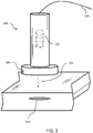
- FIG. 2 shows an alternative version-device 200-that is housed within a disposable bag 212.
- treatment that is provided at a depth does not require direct contact between the device 200 and a target (not shown, see target 102 of FIG. 1 ) to be treated.
- Disposable bag 212 can be a clear plastic bag, for example, that prevents device 200 from being contaminated during a treatment. After the treatment is concluded, disposable bag 212 can be removed and replaced prior to reuse of the device 200.
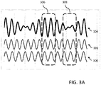
- FIG. 3A depicts the "beat" pattern of two combined sinusoidal waves as mentioned above with respect to FIG. 1 .
- FIG. 3A shows two waves, 300 and 302, that have different frequencies.
- Combined wave 304 is the sum of first wave 302 and second wave 304.
- Each of the waves 300, 302, and 304 are arranged along a common abscissa and separated along the ordinate in FIG. 3A for ease of understanding.
- FIG. 3A shows two regions, 306 and 308, corresponding to constructive and destructive interfering regions, respectively.
- constructive interference at region 306 may be sufficient to cause heating and coagulation
- destructive interference region 308 (and indeed all other regions at which the amplitude of the combined wave 304 is below a threshold) corresponds to regions where no treatment will occur.
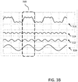
- FIG. 3B shows constructive and destructive interference of three waves rather than two.
- FIGS. 3A and 3B are for illustrative purposes only, and it should be understood that in embodiments there could be any number of oscillators each producing signals having different characteristics from the others to create desired constructive and destructive interference patterns.
- first wave 310, second wave 312, and third wave 314 are all sinusoidal. Each has a different amplitude, phase, and frequency. Their sum, wave 316, can therefore be more complex than the combined wave 304 of FIG. 3A .
- the first wave 310, second wave 312, and third wave 314 are selected as the first three harmonics in the Fourier series for a square wave, for example, though in practice the frequencies, phase shifts, and amplitudes of each wave 310, 312, and 314 can be targeted to create a constructively interfering region 318 at any desired depth.
- FIG. 4A shows a simplified schematic of a signal pathway from a device 400A according to an embodiment towards a target 402.
- device 400A stands off from the target 402 by a distance made up of two parts: a first distance d1 through the air (or other ambient environment), and a second distance d2 through the body of the patient.
- the signal Due to the difference in index of refraction between the environment and the patient's body, the signal has a first portion S1 and a second portion S2, and the wavelength of the signal in second portion S2 is higher than in the first portion S1.
- the antenna 404A of the device 400A can account for the path length as well as the portion of that path length that is within each material having a different index of refraction. While FIG. 4A is designed to show multiple peaks, it should be understood that at least within the body (i.e., in second distance d2) the first peak is preferably at the target treatment site. The signal will also attenuate over distance, especially when the constructive peaks of the signal occur in a material is one in which electromagnetic signals will decay.
- FIG. 4B shows an embodiment of a device 400B that is similar to the device 400A, except that it includes a sensor 406.
- a sensor 406 As shown in FIG. 4B , at each interface between two materials having different indices of refraction there is at least some portion of the signal S1 that is transmitted S2, but another portion that is reflected S3.
- the reflected signal S3 can be detected by sensor 406 to determine the distance D1 and accurately set the frequencies, amplitudes, and phases of the oscillators within the device 400B (not shown) to ensure constructive interference occurs at the target 402.
- the distance can, in embodiments, be determined by use of a visible laser light that can identify the target point.
- sensor 406 need not rely on the reflected wave S3 to determine distance S3, and could instead sense the distance d1 using any of a variety of distance measuring techniques that will be apparent to those of skill in the field of optical systems design, such as by emitting and detecting a reflected infrared, ultrasonic, or visual-region optical beam.
- FIG. 4C shows a third embodiment of a device 400C that is similar to the devices 400A and 400B, except that it operates in contact with (or nearly in contact with) the patient.
- d1 FIGS. 4A , 4B ) is effectively zero.
- FIG. 5 is a design of a device or system as described above.
- an electrosurgical unit (ESU) 500 is connected to a handheld device 502 via a conductor 504.
- ESU electrosurgical unit
- the ESU 500 and the handheld device 502 can be physically separated by a cable or wire (i.e., conductor 504) whereas in other embodiments the conductor 504 is an internal component that connects the ESU 500 and the handheld device 502 within a single housing.
- a processor 506 is configured to operate two oscillators 508Aand 508B. As described above, in various embodiments there could be two, three, or many oscillators.
- the output of the oscillators 508A, 508B, ... 508n are combined at combiner 510 and amplified at amplifier 512. These components can, in some embodiments, be combined into a single operational amplifier.
- the voltages are expected to be: At output of 508 A :sin 2 ⁇ f 1 t + ⁇ 1
- At output of 508B sin 2 ⁇ f 2 t + ⁇ 2
- f 1 and f 2 affect frequency
- ⁇ 1 and ⁇ 2 affect phase offset of 508A and 508B, respectively. From these two equations, it can be expected that the combined voltage output from ESU 500 is: sin 2 ⁇ f 1 t + ⁇ 1 + sin 2 ⁇ f 2 t + ⁇ 2
- Time t to reach the target can be estimated based on the distance to that target, as well as the refractive indices of the various portions of the path to arrive at that target, which can be determined as described above with respect to FIGS. 4A-4C .
- switches 514 are positioned on the handheld device 502. These switches are illustrative only, and in embodiments could be either a simple on-off (as shown) or could be more complex, such as including a depth-setting gauge or a display that indicates distance to a target, distance to the patient, operational state (on, off, error, or power level, for example).
- Handheld device also includes highly-directional antenna 516.
- Directional antenna 516 can provide concentrated and highly-directional, narrowly focused energy towards the target, such as a bleeding vessel.
- the devices and systems described herein provide microwave signal to seal bleeding vessels or provide other similar therapies.
- the outputs of two or more software-controlled microwave controllers with various phase, frequency, and/or amplitude can be combined to create a standing wave at different positions in the transmission path. Accordingly, the resultant microwave signal can be targeted to reach a power suitable to increase a target tissue's temperature based on the location where constructive interference between the two outputs occurs.
- the frequency and phase of the oscillators can be adjusted to achieve the desired depth of effect, and the gain of an amplifier can be adjusted to achieve the desired intensity of the effect.
- Power can be in the range of a few hundred watts and frequency could be in the range of 2-3GHz that could create about 10cm depth of effect, for example.
- FIG. 6 shows a device 600 that includes buttons 608 on the housing thereof.
- device 600 includes an antenna 616 (similar to antenna 516 of FIG. 5 ).
- FIG. 6 shows a forward-sense circuit 618 and a reverse-sense circuit 620 coupled to a transmission line 622.
- the sensed forward power detected by forward-sense circuit 618 can be used to define the relative depth of treatment effect from the device 600.
- the sensed reversed power detected by rear-sense circuit 620 can be used to define what is in front of the antenna (e.g., distance from tissue).
- the enclosure or housing of the device 600 is made from non-electromagnetically sensitive material in front of the antenna to act as a radome to protect the antenna from surgical field while allowing the EM signal to pass through.
- Transmission line 622 can be coupled to another device, such as an ESU, via a cable as previously described.
- the circuitry and/or power supply that drive the antenna 616 can be arranged in the device 600 directly, in embodiments.
- the described techniques may be implemented in hardware, software, firmware, or any combination thereof. If implemented in software, the functions may be stored as one or more instructions or code on a computer-readable medium and executed by a hardware-based processing unit.
- Computer-readable media may include non-transitory computer-readable media, which corresponds to a tangible medium such as data storage media (e.g., RAM, ROM, EEPROM, flash memory, or any other medium that can be used to store desired program code in the form of instructions or data structures and that can be accessed by a computer).
- processors such as one or more digital signal processors (DSPs), general purpose microprocessors, application specific integrated circuits (ASICs), field programmable logic arrays (FPGAs), or other equivalent integrated or discrete logic circuitry.
- DSPs digital signal processors
- ASICs application specific integrated circuits
- FPGAs field programmable logic arrays
- processors may refer to any of the foregoing structure or any other physical structure suitable for implementation of the described techniques. Also, the techniques could be fully implemented in one or more circuits or logic elements.
Landscapes
- Health & Medical Sciences (AREA)
- Surgery (AREA)
- Life Sciences & Earth Sciences (AREA)
- Biomedical Technology (AREA)
- Medical Informatics (AREA)
- Nuclear Medicine, Radiotherapy & Molecular Imaging (AREA)
- Electromagnetism (AREA)
- Engineering & Computer Science (AREA)
- Physics & Mathematics (AREA)
- Heart & Thoracic Surgery (AREA)
- Otolaryngology (AREA)
- Molecular Biology (AREA)
- Animal Behavior & Ethology (AREA)
- General Health & Medical Sciences (AREA)
- Public Health (AREA)
- Veterinary Medicine (AREA)
- Surgical Instruments (AREA)
Applications Claiming Priority (1)
| Application Number | Priority Date | Filing Date | Title |
|---|---|---|---|
| US17/249,103 US20220265347A1 (en) | 2021-02-19 | 2021-02-19 | Microwave sealer device and generator |
Publications (1)
| Publication Number | Publication Date |
|---|---|
| EP4046582A1 true EP4046582A1 (de) | 2022-08-24 |
Family
ID=80628916
Family Applications (1)
| Application Number | Title | Priority Date | Filing Date |
|---|---|---|---|
| EP22157614.3A Pending EP4046582A1 (de) | 2021-02-19 | 2022-02-18 | Mikrowellenabdichtungsvorrichtung und generator |
Country Status (2)
| Country | Link |
|---|---|
| US (1) | US20220265347A1 (de) |
| EP (1) | EP4046582A1 (de) |
Citations (7)
| Publication number | Priority date | Publication date | Assignee | Title |
|---|---|---|---|---|
| US6558385B1 (en) | 2000-09-22 | 2003-05-06 | Tissuelink Medical, Inc. | Fluid-assisted medical device |
| US6702810B2 (en) | 2000-03-06 | 2004-03-09 | Tissuelink Medical Inc. | Fluid delivery system and controller for electrosurgical devices |
| US6953461B2 (en) | 2002-05-16 | 2005-10-11 | Tissuelink Medical, Inc. | Fluid-assisted medical devices, systems and methods |
| US20100145328A1 (en) * | 2006-12-11 | 2010-06-10 | Medical Device Innovations Limited | Electrosurgical ablation apparatus and a method of ablating biological tissue |
| US20100268211A1 (en) * | 2009-04-17 | 2010-10-21 | Kim Manwaring | Inductively Heated Multi-Mode Bipolar Surgical Tool |
| US20130267943A1 (en) * | 2010-12-10 | 2013-10-10 | Creo Medical Limited | Electrosurgical apparatus for rf and microwave delivery |
| US20160013855A1 (en) * | 2013-02-16 | 2016-01-14 | Cable Television Laboratories, Inc. | Multiple-input multiple-output (mimo) communication system |
Family Cites Families (9)
| Publication number | Priority date | Publication date | Assignee | Title |
|---|---|---|---|---|
| AU2001251134B2 (en) * | 2000-03-31 | 2006-02-02 | Angiodynamics, Inc. | Tissue biopsy and treatment apparatus and method |
| US20050251233A1 (en) * | 2004-05-07 | 2005-11-10 | John Kanzius | System and method for RF-induced hyperthermia |
| US20090132015A1 (en) * | 2007-09-04 | 2009-05-21 | Mark Frazer Miller | Method and System for Using Directional Antennas in Medical Treatments |
| US20100087808A1 (en) * | 2008-10-03 | 2010-04-08 | Vivant Medical, Inc. | Combined Frequency Microwave Ablation System, Devices and Methods of Use |
| US20150082624A1 (en) * | 2013-09-24 | 2015-03-26 | Covidien Lp | Aseptic bag to encapsulate an energy source of a surgical instrument |
| US9974595B2 (en) * | 2014-04-04 | 2018-05-22 | Covidien Lp | Systems and methods for optimizing emissions from simultaneous activation of electrosurgery generators |
| GB2559595B (en) * | 2017-02-10 | 2021-09-01 | Creo Medical Ltd | Electrosurgical apparatus and electrosurgical instrument |
| GB201904645D0 (en) * | 2019-04-02 | 2019-05-15 | Emblation Ltd | Microwave treatment system |
| GB2597795A (en) * | 2020-08-07 | 2022-02-09 | Creo Medical Ltd | Modular apparatus for robot-assisted electrosurgery |
-
2021
- 2021-02-19 US US17/249,103 patent/US20220265347A1/en active Pending
-
2022
- 2022-02-18 EP EP22157614.3A patent/EP4046582A1/de active Pending
Patent Citations (9)
| Publication number | Priority date | Publication date | Assignee | Title |
|---|---|---|---|---|
| US6702810B2 (en) | 2000-03-06 | 2004-03-09 | Tissuelink Medical Inc. | Fluid delivery system and controller for electrosurgical devices |
| US7115139B2 (en) | 2000-03-06 | 2006-10-03 | Tissuelink Medical Inc. | Fluid-assisted medical devices, fluid delivery systems and controllers for such devices, and methods |
| US6558385B1 (en) | 2000-09-22 | 2003-05-06 | Tissuelink Medical, Inc. | Fluid-assisted medical device |
| US7645277B2 (en) | 2000-09-22 | 2010-01-12 | Salient Surgical Technologies, Inc. | Fluid-assisted medical device |
| US6953461B2 (en) | 2002-05-16 | 2005-10-11 | Tissuelink Medical, Inc. | Fluid-assisted medical devices, systems and methods |
| US20100145328A1 (en) * | 2006-12-11 | 2010-06-10 | Medical Device Innovations Limited | Electrosurgical ablation apparatus and a method of ablating biological tissue |
| US20100268211A1 (en) * | 2009-04-17 | 2010-10-21 | Kim Manwaring | Inductively Heated Multi-Mode Bipolar Surgical Tool |
| US20130267943A1 (en) * | 2010-12-10 | 2013-10-10 | Creo Medical Limited | Electrosurgical apparatus for rf and microwave delivery |
| US20160013855A1 (en) * | 2013-02-16 | 2016-01-14 | Cable Television Laboratories, Inc. | Multiple-input multiple-output (mimo) communication system |
Also Published As
| Publication number | Publication date |
|---|---|
| US20220265347A1 (en) | 2022-08-25 |
Similar Documents
| Publication | Publication Date | Title |
|---|---|---|
| US20220361948A1 (en) | Systems and methods for energy delivery | |
| EP3629954B1 (de) | Kombination eines ultraschall- und elektrochirurgischen instrumentes mit regulierbaren energieeinstellungen zum verschliessen von gewebe und blockieren der resektion des gewebes | |
| US4878493A (en) | Hand-held diathermy apparatus | |
| US9585709B2 (en) | Square wave for vessel sealing | |
| US8500729B2 (en) | Electrosurgical device with controllable electric field profile | |
| US20060184069A1 (en) | Focused ultrasound for pain reduction | |
| KR20140047709A (ko) | 조직에 초음파원을 연결하는 시스템 및 방법 | |
| EP2499983B1 (de) | Isolierter Stromsensor | |
| CN107334523B (zh) | 电外科发生器和电外科系统 | |
| US20080140063A1 (en) | Non-invasive method and system for using radio frequency induced hyperthermia to treat medical diseases | |
| EP4046582A1 (de) | Mikrowellenabdichtungsvorrichtung und generator | |
| US20240423697A1 (en) | Electrosurgical handpiece with accurate tissue sensing | |
| Nishidate et al. | Study of sleeve inner diameter to suppress backward heating for microwave surgical energy device | |
| Ray-Offor et al. | Energy Sources in Laparoscopic Surgery | |
| Yanenko et al. | High-frequency electrosurgery device with microprocessor control and switching-modulation signal formation | |
| HK40050546A (en) | System for energy delivery | |
| HK40020432B (en) | Apparatus and method for thermally treating ligaments | |
| HK40020432A (en) | Apparatus and method for thermally treating ligaments | |
| Earl | Managing High‐Risk Equipment | |
| HK40001791A (en) | Systems and method for energy delivery | |
| HK40005042B (en) | System for energy delivery | |
| HK40005042A (en) | System for energy delivery | |
| HK40001791B (zh) | 用於能量输送的系统和方法 |
Legal Events
| Date | Code | Title | Description |
|---|---|---|---|
| PUAI | Public reference made under article 153(3) epc to a published international application that has entered the european phase |
Free format text: ORIGINAL CODE: 0009012 |
|
| STAA | Information on the status of an ep patent application or granted ep patent |
Free format text: STATUS: THE APPLICATION HAS BEEN PUBLISHED |
|
| AK | Designated contracting states |
Kind code of ref document: A1 Designated state(s): AL AT BE BG CH CY CZ DE DK EE ES FI FR GB GR HR HU IE IS IT LI LT LU LV MC MK MT NL NO PL PT RO RS SE SI SK SM TR |
|
| STAA | Information on the status of an ep patent application or granted ep patent |
Free format text: STATUS: REQUEST FOR EXAMINATION WAS MADE |
|
| 17P | Request for examination filed |
Effective date: 20230223 |
|
| RBV | Designated contracting states (corrected) |
Designated state(s): AL AT BE BG CH CY CZ DE DK EE ES FI FR GB GR HR HU IE IS IT LI LT LU LV MC MK MT NL NO PL PT RO RS SE SI SK SM TR |
|
| STAA | Information on the status of an ep patent application or granted ep patent |
Free format text: STATUS: EXAMINATION IS IN PROGRESS |