EP4046586A1 - Lichtemittierende vorrichtung und lichtemittierendes system - Google Patents
Lichtemittierende vorrichtung und lichtemittierendes system Download PDFInfo
- Publication number
- EP4046586A1 EP4046586A1 EP20876373.0A EP20876373A EP4046586A1 EP 4046586 A1 EP4046586 A1 EP 4046586A1 EP 20876373 A EP20876373 A EP 20876373A EP 4046586 A1 EP4046586 A1 EP 4046586A1
- Authority
- EP
- European Patent Office
- Prior art keywords
- holding member
- light irradiation
- irradiation device
- optical fiber
- light
- Prior art date
- Legal status (The legal status is an assumption and is not a legal conclusion. Google has not performed a legal analysis and makes no representation as to the accuracy of the status listed.)
- Withdrawn
Links
Images





Classifications
-
- G—PHYSICS
- G02—OPTICS
- G02B—OPTICAL ELEMENTS, SYSTEMS OR APPARATUS
- G02B6/00—Light guides; Structural details of arrangements comprising light guides and other optical elements, e.g. couplings
- G02B6/24—Coupling light guides
- G02B6/36—Mechanical coupling means
- G02B6/3616—Holders, macro size fixtures for mechanically holding or positioning fibres, e.g. on an optical bench
- G02B6/3624—Fibre head, e.g. fibre probe termination
-
- A—HUMAN NECESSITIES
- A61—MEDICAL OR VETERINARY SCIENCE; HYGIENE
- A61N—ELECTROTHERAPY; MAGNETOTHERAPY; RADIATION THERAPY; ULTRASOUND THERAPY
- A61N5/00—Radiation therapy
- A61N5/06—Radiation therapy using light
- A61N5/0613—Apparatus adapted for a specific treatment
- A61N5/062—Photodynamic therapy, i.e. excitation of an agent
-
- A—HUMAN NECESSITIES
- A61—MEDICAL OR VETERINARY SCIENCE; HYGIENE
- A61B—DIAGNOSIS; SURGERY; IDENTIFICATION
- A61B18/00—Surgical instruments, devices or methods for transferring non-mechanical forms of energy to or from the body
- A61B18/18—Surgical instruments, devices or methods for transferring non-mechanical forms of energy to or from the body by applying electromagnetic radiation, e.g. microwaves
-
- A—HUMAN NECESSITIES
- A61—MEDICAL OR VETERINARY SCIENCE; HYGIENE
- A61B—DIAGNOSIS; SURGERY; IDENTIFICATION
- A61B18/00—Surgical instruments, devices or methods for transferring non-mechanical forms of energy to or from the body
- A61B18/18—Surgical instruments, devices or methods for transferring non-mechanical forms of energy to or from the body by applying electromagnetic radiation, e.g. microwaves
- A61B18/20—Surgical instruments, devices or methods for transferring non-mechanical forms of energy to or from the body by applying electromagnetic radiation, e.g. microwaves using laser
- A61B18/22—Surgical instruments, devices or methods for transferring non-mechanical forms of energy to or from the body by applying electromagnetic radiation, e.g. microwaves using laser the beam being directed along or through a flexible conduit, e.g. an optical fibre; Couplings or hand-pieces therefor
- A61B18/24—Surgical instruments, devices or methods for transferring non-mechanical forms of energy to or from the body by applying electromagnetic radiation, e.g. microwaves using laser the beam being directed along or through a flexible conduit, e.g. an optical fibre; Couplings or hand-pieces therefor with a catheter
-
- A—HUMAN NECESSITIES
- A61—MEDICAL OR VETERINARY SCIENCE; HYGIENE
- A61N—ELECTROTHERAPY; MAGNETOTHERAPY; RADIATION THERAPY; ULTRASOUND THERAPY
- A61N5/00—Radiation therapy
- A61N5/06—Radiation therapy using light
- A61N5/0601—Apparatus for use inside the body
-
- G—PHYSICS
- G02—OPTICS
- G02B—OPTICAL ELEMENTS, SYSTEMS OR APPARATUS
- G02B23/00—Telescopes, e.g. binoculars; Periscopes; Instruments for viewing the inside of hollow bodies; Viewfinders; Optical aiming or sighting devices
- G02B23/24—Instruments or systems for viewing the inside of hollow bodies, e.g. fibrescopes
- G02B23/2407—Optical details
- G02B23/2461—Illumination
- G02B23/2469—Illumination using optical fibres
-
- A—HUMAN NECESSITIES
- A61—MEDICAL OR VETERINARY SCIENCE; HYGIENE
- A61N—ELECTROTHERAPY; MAGNETOTHERAPY; RADIATION THERAPY; ULTRASOUND THERAPY
- A61N5/00—Radiation therapy
- A61N5/06—Radiation therapy using light
- A61N5/0601—Apparatus for use inside the body
- A61N2005/0602—Apparatus for use inside the body for treatment of blood vessels
-
- A—HUMAN NECESSITIES
- A61—MEDICAL OR VETERINARY SCIENCE; HYGIENE
- A61N—ELECTROTHERAPY; MAGNETOTHERAPY; RADIATION THERAPY; ULTRASOUND THERAPY
- A61N5/00—Radiation therapy
- A61N5/06—Radiation therapy using light
- A61N2005/063—Radiation therapy using light comprising light transmitting means, e.g. optical fibres
-
- A—HUMAN NECESSITIES
- A61—MEDICAL OR VETERINARY SCIENCE; HYGIENE
- A61N—ELECTROTHERAPY; MAGNETOTHERAPY; RADIATION THERAPY; ULTRASOUND THERAPY
- A61N5/00—Radiation therapy
- A61N5/06—Radiation therapy using light
- A61N2005/0632—Constructional aspects of the apparatus
-
- A—HUMAN NECESSITIES
- A61—MEDICAL OR VETERINARY SCIENCE; HYGIENE
- A61N—ELECTROTHERAPY; MAGNETOTHERAPY; RADIATION THERAPY; ULTRASOUND THERAPY
- A61N5/00—Radiation therapy
- A61N5/06—Radiation therapy using light
- A61N2005/0658—Radiation therapy using light characterised by the wavelength of light used
- A61N2005/0659—Radiation therapy using light characterised by the wavelength of light used infrared
-
- A—HUMAN NECESSITIES
- A61—MEDICAL OR VETERINARY SCIENCE; HYGIENE
- A61N—ELECTROTHERAPY; MAGNETOTHERAPY; RADIATION THERAPY; ULTRASOUND THERAPY
- A61N5/00—Radiation therapy
- A61N5/06—Radiation therapy using light
- A61N5/067—Radiation therapy using light using laser light
-
- G—PHYSICS
- G02—OPTICS
- G02B—OPTICAL ELEMENTS, SYSTEMS OR APPARATUS
- G02B6/00—Light guides; Structural details of arrangements comprising light guides and other optical elements, e.g. couplings
- G02B6/0001—Light guides; Structural details of arrangements comprising light guides and other optical elements, e.g. couplings specially adapted for lighting devices or systems
- G02B6/0005—Light guides; Structural details of arrangements comprising light guides and other optical elements, e.g. couplings specially adapted for lighting devices or systems the light guides being of the fibre type
- G02B6/0008—Light guides; Structural details of arrangements comprising light guides and other optical elements, e.g. couplings specially adapted for lighting devices or systems the light guides being of the fibre type the light being emitted at the end of the fibre
Definitions
- the disclosed embodiments relate to a light irradiation device and a light irradiation system.
- PDT photodynamic therapy
- the photosensitizer is accumulated with low selectivity in the cancer cells, so that the magnitude of the side effects caused by the uptake of the photosensitizer into normal cells is an issue and thus, PDT is not widely used as a treatment technique.
- NIR-PIT near-infrared photoimmunotherapy
- NIR-PIT uses a conjugate in which two compounds, an antibody against a specific antigen of cancer cells and a photosensitizer (for example, IRDye 700DX), are bound.
- this conjugate selectively accumulates in cancer cells in the body.
- the conjugate is activated and exhibits an anticancer effect (see, for example, Patent Literature 1).
- NIR-PIT irradiation with light in the near-infrared region of 690 nm (NIR irradiation) is performed, for example, and thus, an effect of the NIR irradiation on the immune system can also be expected (see, for example, Non-Patent Literature 2).
- a certain wavelength region including the 690 nm region of the example described above is also called a spectroscopic window of a living body.
- light in this wavelength region is absorbed less by biological components than light in other wavelength regions, the light does not sufficiently penetrate when light irradiation is performed from the body surface, and thus, there is a problem in that NIR-PIT cannot be applied to cancers deep inside the body. Therefore, in recent years, research is being conducted on NIR-PIT in which light irradiation is performed at a position closer to the cancer cells, instead of light irradiation from the body surface (see, for example, Non-Patent Literature 3).
- Patent Literature 2 to Patent Literature 4 disclose devices that can be used in such PDT and NIR-PIT.
- Patent Literature 2 to Patent Literature 4 All of the devices described in Patent Literature 2 to Patent Literature 4 are inserted into a living body lumen such as blood vessel to be used, so that the deep inside of the body can be irradiated with a light transmitted by an optical fiber. Also, in the device described in Patent Literature 5, a wound is caused with a laser light in body tissues.
- an optical fiber generally transmits light by total light reflection using a difference in refractive index between a core and a clad covering an outer peripheral surface of the core, and emits light from the core exposed on a distal end of the optical fiber.
- a direction of the light irradiation is preferably a direction of tissues surrounding the living body lumen, i.e. a direction intersecting with a long axial direction of the device.
- the devices described in Patent Literature 4 and Patent Literature 5 include a guide means (guide member), and the optical fiber is moved using the guide means, so that the distal end of the optical fiber can be oriented in a direction intersecting with the long axial direction of the device.
- the techniques described in Patent Literature 4 and Patent Literature 5 have had a problem that the device has a complicated structure and an increased diameter.
- the devices described in Patent Literature 2 and Patent Literature 3 the light irradiation in the direction intersecting with the long axial direction of the device is not taken into consideration.
- this problem is not limited to PDT and NIR-PIT, and is common to all devices used in examinations or treatments including a light irradiation process in the body. Further, such a problem is not limited to devices to be inserted into a blood vessel, and is common to all devices to be inserted into living body lumens, such as a vascular system, a lymphatic system, a biliary system, a urinary system, a respiratory system, a digestive system, a secretory gland, and a reproductive organ.
- the disclosed embodiments have been contrived to solve at least a part of the above-mentioned problems, and an object of the disclosed embodiments is to decrease a diameter of a device that can emit light from an optical fiber in a direction intersecting with a long axial direction of the device.
- a light irradiation device having an elongated outer shape includes: an optical fiber that emits a light from its distal end and includes a curved part, in which the curved part orients the distal end in a direction intersecting with a long axial direction of the light irradiation device; a light transmitting holding member that retains a shape of the curved part of the optical fiber.
- the optical fiber includes a core, or the optical fiber includes the core and one or more covering layers, and the holding member has a refractive index lower than of a member constituting an outer surface of the optical fiber.
- the shape of the curved part is retained by the holding member.
- movement of the optical fiber by using a guide means simplifies the configuration of the light irradiation device compared to a configuration in which the distal end of the optical fiber is oriented in a direction intersecting with the long axial direction of the light irradiation device, so that the diameter of the light irradiation device can be decreased.
- the holding member has a refractive index lower than of the member constituting the outer surface of the optical fiber.
- the light inside the optical fiber can be reflected at a boundary between the member constituting the outer surface of the optical fiber and the holding member e.g. compared to a case where the shape of the curved part is retained using a holding member having a refractive index equivalent to or higher than that of the member constituting the outer surface of the optical fiber.
- the light irradiation device having this configuration makes it possible to reduce light leakage from the inside of the optical fiber.
- the holding member may be arranged at least adjacent to an inner peripheral side of the curved part.
- the shape of the curved part of the optical fiber can be retained at least from the inner peripheral side of the curved part.
- the inner peripheral side of the curved part is, in other words, a direction in which the distal end of the optical fiber is oriented, i.e. a direction in which the light is emitted from the optical fiber.
- the material for forming the holding member has a refractive index higher than of air.
- the light leakage in the direction not for the light emission from the optical fiber can be further reduced, by leaving a void on the outer peripheral side (direction in which the light is not emitted from the optical fiber) of the curved part without disposing the holding member.
- the holding member includes an inner holding member arranged adjacent to the inner peripheral side of the curved part and an outer holding member arranged adjacent to the outer peripheral side of the curved part, and the outer holding member may have a refractive index lower than of the inner holding member.
- the shape of the curved part can be firmly retained from different directions of the inner peripheral side and the outer peripheral side of the curved part.
- the outer holding member disposed on the outer peripheral side of the curved part has a refractive index lower than of the inner holding member disposed on the inner peripheral side of the curved part.
- the inner holding member includes a first inner holding member disposed on the distal end side and a second inner holding member disposed on the proximal end side, and the second inner holding member may have a refractive index lower than of the first inner holding member and higher than of the outer holding member.
- the inner holding member includes the first inner holding member disposed on the distal end side and the second inner holding member disposed on the proximal end side
- a degree of the light leakage can be changed by controlling the refractive indices of the first and second inner holding members.
- the second inner holding member has a refractive index lower than of the first inner holding member and higher than of the outer holding member.
- the light leakage from the outer holding member arranged in the direction not for the light emission from the optical fiber can be more reduced compared to the light leakage from the first and second inner holding members arranged in the direction of the light emission from the optical fiber.
- the light leakage from the second inner holding member disposed on the proximal end side can be more reduced compared to the light leakage from the first inner holding member disposed on the distal end side.
- the light irradiation device further includes a hollow shaft accommodating the optical fiber and the holding member, wherein the proximal end side with respect to the holding member within the hollow shaft may be filled with a resin member having a refractive index lower than of the holding member.
- the proximal end side with respect to the holding member within the hollow shaft is filled with the resin member, the elongated shape of the light irradiation device can be maintained.
- the resin member has the refractive index lower than of the holding member, the light leakage can be reduced via the resin member.
- a part on the distal end side of the curved part protrudes from the distal end of the hollow shaft, and the holding member may cover the periphery of the curved part protruding from the hollow shaft.
- a part on the distal end side of the curved part i.e. the distal end of the optical fiber is protruded from the distal end of the hollow shaft, so that the light emitted from the distal end of the optical fiber can be prevented from being blocked by the hollow shaft.
- the holding member covers the periphery of the protruding curved part, the periphery of the protruding curved part can be protected.
- the light irradiation device further includes the hollow shaft accommodating the optical fiber and the holding member, wherein a part on the distal end side of the curved part protrudes from the distal end of the hollow shaft, and the holding member may cover the periphery of the curved part protruding from the hollow shaft and have substantially the same outer diameter as of the hollow shaft so as to be joined to the distal end of the hollow shaft.
- a part on the distal end side of the curved part i.e. the distal end of the optical fiber is protruded from the distal end of the hollow shaft, so that the light emitted from the distal end of the optical fiber can be prevented from being blocked by the hollow shaft.
- the holding member covers the periphery of the protruding curved part, the periphery of the protruding curved part can be protected.
- a light irradiation system includes the light irradiation device according to the aspects described above, an elongated tubular catheter into which the light irradiation device is inserted, wherein the catheter has a light transmitting portion for transmitting the inside light to the outside, at a position corresponding to the distal end of the optical fiber in inserting the light irradiation device into the catheter.
- the light irradiation system includes separately the light irradiation device, and the catheter having a light transmitting portion for transmitting the inside light to the outside, at a position corresponding to the distal end of the optical fiber, and therefore the degree of freedom in designing the device can be improved and the range of procedures can be expanded.
- the disclosed embodiments can be realized in various aspects, for example, the disclosed embodiments can be realized in aspects such as a catheter, a light irradiation device, a light irradiation system in which the catheter and the light irradiation device are provided separately or integrally, and a manufacturing method of the catheter, the light irradiation device, and the light irradiation system.
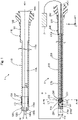
- Fig. 1 is an explanatory diagram illustrating a configuration of a light irradiation system according to the first embodiment.
- the light irradiation system is inserted into a living body lumen such as a vascular system, a lymphatic system, a biliary system, a urinary system, a respiratory system, a digestive system, a secretory gland, and a reproductive organ to be used.
- the light irradiation system emits a light transmitted through an optical fiber, from the living body lumen toward living tissues.
- the light irradiation system can be used in photodynamic therapy (PDT) and near-infrared photoimmunotherapy (NIR-PIT), for example.
- the light irradiation system includes a catheter 1 and a light irradiation device 2 that is inserted into the catheter 1 to be used. In Fig. 1 , the catheter 1 and the light irradiation device 2 are illustrated separately.
- an axis passing through a center of the catheter 1 and an axis passing through a center of the light irradiation device 2 are represented by an axis O (dash-dot-dash line).
- axis O dashed-dot-dash line
- the X-axis corresponds to a long axial direction (axis O direction) of the catheter 1 and the light irradiation device 2
- the Y-axis corresponds to a height direction of the catheter 1 and the light irradiation device 2
- the Z-axis corresponds to a width direction of the catheter 1 and the light irradiation device 2.
- distal end side of the catheter 1, the light irradiation device 2, and each constitution component
- the right side (a + X-axis direction) in Fig. 1 is referred to as a "proximal end side" of the catheter 1, the light irradiation device 2, and each constitution component.
- End portions of the catheter 1, the light irradiation device 2, and each constitution component located on the distal end side are referred to as a "distal end", and the distal end and a vicinity thereof are referred to as a "distal end portion".
- proximal end an end portion located on the proximal end side
- proximal end and the vicinity thereof are referred to as a "proximal end portion”.
- the distal end side corresponds to a “distal side” inserted into a living body
- the proximal end side corresponds to a "proximal side” operated by an operator such as a doctor.
- the catheter 1 has an elongated tube shape and includes a shaft 110, a distal tip 120, and a connector 140.
- the shaft 110 is an elongated member extending along the axis O.
- the shaft 110 has a substantially hollow cylindrical (tubular) shape and both ends of the shaft 110, i.e., a distal end portion 110d and a proximal end portion 110p, are open.
- the shaft 110 includes a lumen 110L inside the shaft 110.
- the lumen 110L functions as a guide wire lumen for inserting a guide wire through the catheter 1 during delivery of the catheter 1.
- the lumen 110L functions as a device lumen for inserting the light irradiation device 2 into the catheter 1 after the delivery of the catheter 1.
- Using a single lumen as both the guide wire lumen and the device lumen, as described above, makes it possible to reduce the diameter of the catheter 1.
- the shaft 110 may have any outer diameter, inner diameter, and length.
- the distal tip 120 is a member that is joined to the distal end portion of the shaft 110 and advances in a living body lumen ahead of other members. As illustrated in Fig. 1 , to facilitate the progress of the catheter 1 in the living body lumen, the distal tip 120 has an outer shape with a diameter that decreases from the proximal end side to the distal end side. A through-hole 12th penetrating the distal tip 120 in a direction of the axis O is formed in a substantially central part of the distal tip 120.
- an opening diameter ⁇ 1 of the through-hole 120h is smaller than an inner diameter ⁇ 2 of the lumen 110L of the shaft 110. Therefore, as illustrated in Fig.
- an inner surface 120i of the distal tip 120 protrudes and forms a step.
- An opening 120o of the distal tip 120 leads to the through-hole 120h and is used when inserting a guide wire (not illustrated) into the catheter 1.
- the distal tip 120 may have any outer diameter and length.
- the connector 140 is a member arranged on the proximal end side of the catheter 1 and gripped by the operator.
- the connector 140 includes a connection portion 141 having a substantially cylindrical shape and a pair of blades 142.
- a distal end portion of the connection portion 141 is joined to the proximal end portion 110p of the shaft 110, and a proximal end portion of the connection portion 141 is joined to the blades 142.
- the blades 142 may have a structure that is integrally formed with the connector 140.
- An opening 140o of the connector 140 leads to the lumen 110L via the inside of the connector 140, and is used when inserting the light irradiation device 2 into the catheter 1.
- the connection portion 141 may have any outer diameter, inner diameter, and length, and the blades 142 may have any shape.
- the shaft 110 of the catheter 1 is further provided with a light transmitting portion 139 and first marker portions 131 and 132.
- the light transmitting portion 139 transmits light inside the shaft 110 to the outside.
- the light transmitting portion 139 is a hollow member having a substantially cylindrical shape, an outer diameter that is substantially the same as the outer diameter of the shaft 110, and an inner diameter that is substantially the same as the inner diameter ⁇ 2 of the lumen 110L of the shaft 110.
- the light transmitting portion 139 is provided wholly in the circumferential direction, and wholly transmits light inside the shaft 110 to the outside in the circumferential direction.
- the light transmitting portion 139 is joined to the shaft 110 at each of the proximal end side and the distal end side.
- the light transmitting portion 139 can be formed of a transparent resin material having light-transmitting properties, such as an acrylic resin, polyethylene terephthalate, and polyvinyl chloride.
- the first marker portions 131 and 132 function as marks indicating positions of the light transmitting portion 139.
- the first marker portion 131 is provided close to the distal end portion of the light transmitting portion 139, and functions as a mark indicating a position of the distal end portion of the light transmitting portion 139.
- the first marker portion 132 is provided close to the proximal end portion of the light transmitting portion 139, and functions as a mark indicating a position of the proximal end portion of the light transmitting portion 139.
- the first marker portions 131 and 132 are hollow members each having a substantially cylindrical shape. In the example of Fig.
- the first marker portions 131 and 132 are respectively arranged in recess portions formed in an outer surface of the shaft 110 and are joined to the outer surface of the shaft 110.
- the first marker portions 131 and 132 are each embedded in the outer surface of the shaft 110 to surround the shaft 110 in the circumferential direction. It is noted that the first marker portions 131 and 132 may be joined to the outer surface of the shaft 110 without the recess portions, and may protrude from the outer surface of the shaft 110. At least one of the first marker portions 131 and 132 may be omitted.
- the light irradiation device 2 has an elongated outer shape and includes a shaft 210, a distal tip 220, a connector 240, an optical fiber 250, and a holding member 260.
- the shaft 210 is an elongated member extending along the axis O.
- the shaft 210 has a hollow and substantially cylindrical (tubular) shape with both end portions, a distal end portion 210d and a proximal end portion 210p being opened.
- An opening for exposing the distal end of the optical fiber 250 is formed on the outer peripheral surface on the distal end side of the shaft 210 (described later in Fig. 3 ).
- the optical fiber 250 and the holding member 260 are accommodated in (inside) the shaft 210. Avoid portion inside the shaft 210 excluding the optical fiber 250 and the holding member 260 is filled with a resin member 270. Note that the shaft 210 corresponds to the "hollow shaft”.
- the distal tip 220 is a member that is joined to the distal end portion 210d of the shaft 210 and advances ahead of other members in the lumen 110L of the catheter 1. As illustrated in Fig. 1 , the distal tip 220 is an almost columnar member extending in the long axis direction of the light irradiation device 2.
- an outer diameter ⁇ 3 of the distal tip 220 and the shaft 210 is larger than the opening diameter ⁇ 1 of the through-hole 120h of the catheter 1 and smaller than an inner diameter ⁇ 2 of the shaft 110 and the light transmitting portion 139 of the catheter 1 ( ⁇ 1 ⁇ 3 ⁇ 2).
- the connector 240 is a member arranged on the proximal end side of the light irradiation device 2 and gripped by the operator.
- the connector 240 includes a connection portion 241 having a substantially cylindrical shape and a pair of blades 242. A distal end portion of the connection portion 241 is joined to the proximal end portion 210p of the shaft 210, and a proximal end portion of the connection portion 241 is joined to the blades 242.
- the blades 242 may have a structure that is integrally formed with the connector 240.
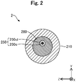
- Fig. 2 is an explanatory diagram illustrating a cross-sectional configuration taken along line A-A in Fig. 1 .
- the X-axis, Y-axis, and Z-axis illustrated in Fig. 2 correspond to the X-axis, Y-axis, and Z-axis respectively in Fig. 1 .
- the optical fiber 250 includes a core 250c extending in the long axial direction (axis O direction) of the light irradiation device 2, and a clad 250cl that covers an outer peripheral surface (outer surface) of the core 250c.
- the core 250c is disposed substantially in the center of the clad 250cl and has a higher optical refractive index than of the clad 250cl.
- the clad 250cl has a uniform refractive index.
- the optical fiber 250 transmits the light by total light reflection using a difference in refractive index between the core 250c and the clad 250cl.
- the clad 250cl corresponds to a "covering layer” that covers the core 250c and corresponds to a "member constituting the outer surface of the optical fiber 250".
- the optical fiber 250 is a plastic optical fiber in which the core 250c and the clad 250cl are both made of a resin.
- the core 250c can be made of e.g. a polymethylmetacrylate (PMMA), a polystyrene, a polycarbonate, a deuterated polymer, a fluorine-based polymer, a silicon-based polymer, a norbornene-based polymer, or the like.
- PMMA polymethylmetacrylate
- the core 250c is classified into a single-mode and a multi-mode depending on the number of modes for propagating the light, but either the single-mode or the multi-mode may be used in the first embodiment.
- the core 250c is classified into a step index and a graded index depending on a refractive index distribution, but either the step index or the graded index may be used in the first embodiment.
- the clad 250cl can be made of e.g. a fluorine-based polymer.
- a quartz glass optical fiber or a multi-component glass optical fiber may be employed instead of the plastic optical fiber.
- a longitudinal length of the optical fiber 250 can be arbitrarily determined.
- the distal end side of the optical fiber 250 is inserted inside the shaft 210 and fixed by the resin member 270.
- the proximal end side of the optical fiber 250 passes through the inside of the connector 240 and is pulled out to the outside.
- the proximal end portion of the optical fiber 250 is connected to a light source 3 via a connector not illustrated, directly, or indirectly via another optical fiber.
- the light source 3 is e.g. a laser light generator that generates a laser light at any wavelength.
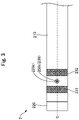
- Fig. 3 is a top view of the light irradiation device 2 viewed from direction B in Fig. 1 .
- a curved part 251 where the optical fiber 250 is curved in the + Y-axis direction is formed on the distal end portion of the optical fiber 250.
- the distal end (distal end surface) of the optical fiber 250 is arranged so as to be exposed on the outer peripheral surface (outer surface) of the shaft 210.
- the clad 250cl is removed and the core 250c is exposed.
- a laser light LT generated by the light source 3 and transmitted through the optical fiber 250 is emitted from the exposed core 250c.
- the core 250c exposed on the distal end of the optical fiber 250 functionally serves as a light irradiation portion 239 that emits the light LT to the outside.
- the distal end of the optical fiber 250 that emits the laser light LT is oriented in a direction intersecting with the long axial direction (axis O direction) of the light irradiation device 2, by the curved part 251 of the optical fiber 250.
- the light LT is emitted from the core 250c (light irradiation portion 239) exposed on the distal end of the optical fiber 250 toward one direction of the side surface of the light irradiation device 2.
- the core 250c On the distal end (distal end surface) of the optical fiber 250, the core 250c may be subjected to a well-known process (e.g. a process of diagonally cutting a distal end surface, a process of forming a notch, a sandblast process, and a chemical process).
- a resin body or a light reflecting mirror for transmitting, refracting, or amplifying the laser light LT may be disposed on or near the distal end of the core 250c.
- the resin body can be formed, for example, by applying an acrylic ultraviolet-curable resin containing dispersed fine quartz powder, and curing the resin using ultraviolet light.
- the holding member 260 is a member for retaining a shape (curved shape) of the curved part 251 of the optical fiber 250.
- the holding member 260 is disposed inside the shaft 210 and at a position of the curved part 251 of the optical fiber 250 ( Fig. 1 ).
- the holding member 260 is arranged so as to cover the entire outer peripheral surface of the curved part 251 of the optical fiber 250 ( Fig. 2 ).
- the holding member 260 is made of a light transmissive resin.
- light transmissive resin means a resin that is transparent or translucent and has a property of transmitting light.
- any resin such as an epoxy resin filled with an inorganic powder can be used.
- a light transmissivity in a wavelength range used in PDT or NIR-PIT is preferably higher than the light transmissivity in another wavelength range.
- the holding member 260 may be formed by mixing plural different types of light transmissive resins.
- This light transmitting holding member 260 has a refractive index 6R lower than a refractive index R5 of the member constituting the outer surface of the optical fiber 250 (i.e. clad 250cl) (R6 ⁇ R5).
- the resin member 270 has a refractive index R7 lower than the refractive index R6 of the holding member 260 (R7 ⁇ R6). That means, the relationship between the refractive index R5 of the clad 250cl, the refractive index R6 of the holding member 260, and the refractive index R7 of the resin member 270 is represented by "R7 ⁇ R6 ⁇ R5". Representative values such as catalogue values can be used for the refractive index R5 of the clad 250cl, the refractive index R6 of the holding member 260, and the refractive index R7 of the resin member 270.
- first member and a second member having different refractive indices are arranged adjacent to each other.
- the smaller the difference in refractive index between the first member and the second member the more likely it is that the light advances from the first member to the second member while being refracted at the boundary surface between the first and second members.
- the refractive index R6 of the holding member 260 is lower than the refractive index R5 of the clad 250cl constituting the outer surface of the optical fiber 250 (R6 ⁇ R5).
- the light inside the optical fiber 250 can be reflected at a boundary between the clad 250cl and the holding member 260, compared to the case where the shape of the curved part 251 is retained using the holding member having a refractive index equivalent to or higher than the refractive index of the clad 250cl.
- the light leakage can be reduced via the holding member 260.
- the resin member 270 has a refractive index R7 lower than the refractive index R6 of the holding member 260 (R7 ⁇ R6). For this reason, when comparing the resin member 270 with the holding member 260, the difference in refractive index between the resin member 270 and the clad 250cl is larger than the difference in refractive index between the holding member 260 and the clad 250cl. Consequently, the light leakage can be reduced via the resin member 270.
- the optical fiber 250 consists only of the core 250c and need not have any covering layer such as the clad 250cl.
- the core 250c corresponds to the "member constituting the outer surface of the optical fiber 250".
- the refractive index R6 of the holding member 260 is lower than a refractive index R51 of the core 250c (R6 ⁇ R51).
- the optical fiber 250 may further include a cover for covering the outer peripheral surface of the clad 250cl.
- the clad 250cl and the cover correspond to the "covering layer" for covering the core 250c, and the cover corresponds to the "member constituting the outer surface of the optical fiber 250".
- the refractive index R6 of the holding member 260 is lower than a refractive index R52 of the cover (R6 ⁇ R52). Furthermore, when the cover is composed of a plurality of layers, the outermost cover corresponds to the "member constituting the outer surface of the optical fiber 250". At this time, the refractive index R6 of the holding member 260 is lower than a refractive index R53 of the outermost cover (R6 ⁇ R53).
- Second marker portions 231 and 232 are further disposed on the shaft 210 of the light irradiation device 2.
- the second marker portions 231 and 232 function as marks indicating positions of the light irradiation portion 239 (i.e. the distal end of the optical fiber 250).
- the second marker portion 231 is provided close to the distal end side of the light irradiation portion 239, and functions as a mark indicating a position of the distal end side of the light irradiation portion 239.
- the second marker portion 232 is provided close to the proximal end side of the light irradiation portion 239, and functions as a mark indicating a position of the proximal end side of the light irradiation portion 239.
- the second marker portions 231 and 232 are hollow members each having a substantially cylindrical shape.
- the second marker portions 231 and 232 are respectively arranged in recess portions formed in the outer surface of the shaft 210 and are joined to the outer surface of the shaft 210.
- the second marker portions 231 and 232 are each embedded in the outer surface of the shaft 210 to surround the shaft 210 in a circumferential direction.
- the second marker portions 231 and 232 may be joined to the outer surface of the shaft 210 without the recess portions, and may protrude from the outer surface of the shaft 210. At least one of the second marker portions 231 and 232 may be omitted.
- the first marker portions 131 and 132 of the catheter 1 and the second marker portions 231 and 232 of the light irradiation device 2 can be formed of a radiopaque resin material or a radiopaque metal material.
- a resin material such as bismuth trioxide, tungsten, or barium sulfate
- a resin material such as a polyamide resin, a polyolefin resin, a polyester resin, a polyurethane resin, a silicon resin, or a fluororesin.
- the first marker portions 131 and 132 and the second marker portions 231 and 232 can be formed of a radiopaque material such as gold, platinum, tungsten, or an alloy containing these elements (for example, a platinum-nickel alloy).
- a radiopaque material such as gold, platinum, tungsten, or an alloy containing these elements (for example, a platinum-nickel alloy).
- the shaft 110 of the catheter 1, the shaft 210 of the light irradiation device 2, and the resin member 270 of the light irradiation device 2 are preferably antithrombotic, flexible, and biocompatible, and can be formed of a resin material or a metal material.
- a resin material or a metal material for example, a polyamide resin, a polyolefin resin, a polyester resin, a polyurethane resin, a silicon resin, a fluororesin, and the like can be employed as the resin material.
- stainless steel such as SUS304, a nickel-titanium alloy, a cobalt-chromium alloy, tungsten steel and the like can be employed as the metal material.
- the shaft 110 and the shaft 210 can be formed as a bonded structure in which a plurality of the above-mentioned materials are combined.
- the distal tip 120 of the catheter 1 and the distal tip 220 of the light irradiation device 2 are preferably flexible, and can be formed of, for example, a resin material such as polyurethane and a polyurethane elastomer.
- the connector 140 of the catheter 1 and the connector 240 of the light irradiation device 2 can be formed of a resin material such as a polyamide, a polypropylene, a polycarbonate, a polyacetal, and a polyether sulfone.
- Fig. 4 is an explanatory diagram illustrating a usage state of the light irradiation system. A method of using the light irradiation system will be described with reference to Figs. 1 and 4 .
- an operator inserts a guide wire into a living body lumen.
- the operator inserts a proximal end side of the guide wire from the opening 120o of the distal tip 120 of the catheter 1 illustrated in Fig. 1 , through the lumen 110L so that the guide wire protrudes from the opening 140o of the connector 140.
- the operator pushes the catheter 1 into the living body lumen along the guide wire, and the light transmitting portion 139 of the catheter 1 is delivered to a target site for light irradiation (for example, in the case of NIR-PIT, a vicinity of a cancer cell).
- a target site for light irradiation for example, in the case of NIR-PIT, a vicinity of a cancer cell.
- the operator inserts the light irradiation device 2 from the opening 140o of the connector 140 of the catheter 1.
- the operator pushes the light irradiation device 2 toward the distal end side of the catheter 1, along the lumen 110L of the catheter 1.
- a distal end surface 220e of the light irradiation device 2 abuts against the inner surface 120i of the distal tip 120 when the light irradiation device 2 is inserted into the catheter 1, and thus, it is possible to prevent the light irradiation device 2 from being advanced beyond the distal end of the catheter 1 ( Fig. 4 ).
- the operator aligns the light irradiation portion 239 (distal end of the optical fiber 250) with the light transmitting portion 139 in the direction of the axis O (X-axis direction), while observing, in an X-ray image, a positional relationship between the first marker portions 131 and 132 and the second marker portions 231 and 232.
- the laser light LT emitted from the light irradiation portion 239 (distal end of the optical fiber 250) can be transmitted through the light transmitting portion 139 of the catheter 1 and emitted to a living tissue on the outside.
- the light transmitting portion 139 is provided in the entire circumferential direction.
- the operator only needs to achieve alignment between the light transmitting portion 139 and the light irradiation portion 239 in the direction of the axis O (X-axis direction), and does not need to achieve alignment between the light transmitting portion 139 and the light irradiation portion 239 in the circumferential direction.
- the shape of the curved part 251 is retained by the holding member 260 ( Fig. 4 ).
- movement of the optical fiber by using a guide means simplifies the configuration of the light irradiation device 2 compared to a configuration in which the distal end of the optical fiber is oriented in a direction intersecting with the long axial direction of the light irradiation device, so that the diameter of the light irradiation device 2 can be decreased.
- the refractive index R6 of the holding member 260 is lower than the refractive index R5 of the clad 250cl (member constituting the outer surface of the optical fiber 250).
- the light inside the optical fiber 250 can be reflected at the boundary between the clad 250cl and the holding member 260, compared to the case where the shape of the curved part 251 is retained using the holding member having a refractive index equivalent to or higher than the refractive index of the clad 250cl.
- the light irradiation device 2 according to the first embodiment makes it possible to reduce light leakage from the inside of the optical fiber 250.
- the proximal end side with respect to the holding member 260 within the shaft 210 (hollow shaft) is filled with the resin member 270.
- the resin member 270 is filled with the resin member 270.
- the refractive index R7 of the resin member 270 is lower than the refractive index R6 of the holding member 260. Consequently, as explained in Fig. 2 , the light leakage can be reduced via the resin member 270.
- the light irradiation system according to the first embodiment separately includes the light irradiation device 2, and the catheter 1 having the light transmitting portion 139 for transmitting the inside light LT to the outside, which is disposed at a position corresponding to the distal end (i.e. the light irradiation portion 239) of the optical fiber 250. Consequently, the degree of freedom in designing the device can be improved and also the range of procedures can be expanded.
- Fig. 5 is an explanatory diagram illustrating a configuration of a light irradiation device 2A according to the second embodiment.
- Fig. 6 is an explanatory diagram illustrating a cross-sectional configuration taken along line C-C of Fig. 5 .
- a light irradiation system according to the second embodiment includes the catheter 1 explained in the first embodiment and the light irradiation device 2A illustrated in Fig. 5 and Fig. 6 .
- the light irradiation device 2A includes a holding member 260A instead of the holding member 260 and does not include the resin member 270.
- the holding member 260A is arranged adjacent to the inner peripheral side of the curved part 251 of the optical fiber 250.
- the inner peripheral side of the curved part 251 means the inner side of the curved part on the outer peripheral surface of the optical fiber 250, and means, in the examples of Fig. 5 and Fig. 6 , the + Y-axis direction side.
- the resin member 270 is disposed on the outer peripheral side ( Fig. 5 and Fig. 6 : - Y-axis direction side) of the curved part 251 of the optical fiber 250.
- a dimensional relationship in refractive index between the clad 250cl, the holding member 260A, and the resin member 270 is the same as in the first embodiment.
- the configuration of the holding member 260A of the light irradiation device 2A can be modified in various ways, and the holding member 260A may be disposed only on the inner peripheral side of the curved part 251 of the optical fiber 250.
- the holding member 260A is disposed on the inner peripheral side of the curved part 251 over a range of about 170 degrees in the circumferential direction, but the range in which the holding member 260A is arranged can be arbitrarily changed.
- the angular range may be e.g. 30 degrees, 90 degrees, or 270 degrees.
- the outer peripheral side of the curved part 251 is filled with the resin member 270, the outer peripheral side of the curved part 251 need not be filled with the resin member 270, and may be e.g. a void.
- the light irradiation system according to the second embodiment as described above makes it possible to exhibit an effect similar to that in the first embodiment described above.
- the shape of the curved part 251 of the optical fiber 250 can be retained from at least the inner peripheral side of the curved part 251.
- the inner peripheral side of the curved part 251 is, in other words, a direction in which the distal end of the optical fiber 250 is oriented (i.e. a direction toward the light irradiation portion 239) and is the direction in which the light LT is emitted from the optical fiber 250.
- the whole of the materials constituting the holding member 260A has a refractive index higher than of air.
- the light leakage in the direction not for the light emission from the optical fiber 250 can be further reduced, by leaving a void on the outer peripheral side (direction in which the light is not emitted from the optical fiber 250) of the curved part 251 without disposing the holding member 260A and the resin member 270, as in the light irradiation device 2A according to the second embodiment.
- Fig. 7 is an explanatory diagram illustrating a configuration of a light irradiation device 2B according to the third embodiment.
- Fig. 8 is an explanatory diagram illustrating a cross-sectional configuration taken along line D-D of Fig. 7 .
- Alight irradiation system according to the third embodiment includes the catheter 1 explained in the first embodiment and the light irradiation device 2B illustrated in Fig. 7 and Fig. 8 .
- the light irradiation device 2B includes a holding member 260B instead of the holding member 260.
- the holding member 260B includes an inner holding member 261 and an outer holding member 262.
- the inner holding member 261 is arranged adjacent to the inner peripheral side of the curved part 251 of the optical fiber 250.
- the outer holding member 262 is arranged adjacent to the outer peripheral side of the curved part 251 of the optical fiber 250.
- the inner holding member 261 is disposed on the inner peripheral side of the curved part 251 over a range of about 170 degrees in the circumferential direction
- the outer holding member 262 is disposed on the outer peripheral side of the curved part 251 over the remaining angular range (range of about 190 degrees) in the circumferential direction.
- the angular range in which the inner holding member 261 is disposed in the circumferential direction and the angular range in which the outer holding member 262 is disposed in the circumferential direction can be arbitrarily changed.
- the inner holding member 261 and the outer holding member 262 are each made of different light transmissive resins.
- the outer holding member 262 has a refractive index R62 lower than a refractive index R61 of the inner holding member 261 (R62 ⁇ R61).
- R62 ⁇ R61 refractive index of the inner holding member 261
- the refractive indices R61 and R62 of the holding member 260B are both lower than the refractive index R5 of the clad 250cl constituting the outer surface of the optical fiber 250.
- a dimensional relationship therebetween is represented by R62 ⁇ R61 ⁇ R5.
- the configuration of the holding member 260B of the light irradiation device 2B can be modified in various ways, and the holding member 260B may include the inner holding member 261 and the outer holding member 262 which are each made of different light transmissive resins.
- the light irradiation system according to the third embodiment as described above makes it possible to exhibit an effect similar to that in the first embodiment described above.
- the shape (curved shape) of the curved part 251 can be firmly retained from different directions of the inner peripheral side and the outer peripheral side of the curved part 251.
- the refractive index R62 of the outer holding member 262 disposed on the outer peripheral side (the opposite side to the light LT-emitting side, i.e. - Y-axis direction in the example of Fig. 7 ) of the curved part 251 is lower than the refractive index R61 of the inner holding member 261 disposed on the inner peripheral side (the light LT-emitting side, i.e. + Y-axis direction in the example of Fig. 7 ) of the curved part 251.
- the difference in refractive index between the outer holding member 262 and the clad 250cl is larger than the difference in refractive index between the inner holding member 261 and the clad 250cl.
- the light leakage from the outer holding member 262 arranged in the direction not for the light emission from the optical fiber 250 can be more reduced compared to the light leakage from the inner holding member 261 arranged in the direction of the light emission from the optical fiber 250.
- the dimensional relationship between the refractive index R61 of the inner holding member 261 and the refractive index R62 of the outer holding member 262 may be reversed (R61 ⁇ R62). Also, the refractive index R61 of the inner holding member 261 and the refractive index R62 of the outer holding member 262 may be substantially equal. Also in this way, the same effect as in the first embodiment can be exhibited, and the shape of the curved part 251 can be firmly retained from different directions of the inner peripheral side and the outer peripheral side of the curved part 251.
- Fig. 9 is an explanatory diagram illustrating a configuration of a light irradiation device 2C according to the fourth embodiment.
- Fig. 10 is an explanatory diagram illustrating a cross-sectional configuration taken along line E-E of Fig. 9 .
- Alight irradiation system according to the fourth embodiment includes the catheter 1 explained in the first embodiment and the light irradiation device 2C illustrated in Fig. 9 and Fig. 10 .
- the light irradiation device 2C includes a holding member 260C instead of the holding member 260.
- the holding member 260C includes an inner holding member 261C and an outer holding member 262C.
- the inner holding member 261C is disposed on the inner peripheral side of the curved part 251 of the optical fiber 250 over a range of about 100 degrees in the circumferential direction.
- the outer holding member 262C is disposed on the outer peripheral side of the curved part 251 of the optical fiber 250 over a range of about 100 degrees in the circumferential direction.
- a portion in the remaining angle range in the circumferential direction is filled with the resin member 270, the portion in the remaining angle range in the circumferential direction of the curved part 251 need not be filled with the resin member 270, and may be e.g. a void.
- the materials of the inner holding member 261C and the outer holding member 262C are the same as in the third embodiment.
- a dimensional relationship in refractive index between the inner holding member 261C, the outer holding member 262C, and the clad 250cl is the same as in the third embodiment (R62 ⁇ R61 ⁇ R5).
- the configuration of the holding member 260C of the light irradiation device 2C can be modified in various ways, and the holding member 260C may include the inner holding member 261C and the outer holding member 262C, which are arranged apart from each other in the circumferential direction. Also, the light irradiation system according to the fourth embodiment as described above makes it possible to exhibit an effect similar to those in the first and fourth embodiments described above.
- Fig. 11 is an explanatory diagram illustrating a configuration of a light irradiation device 2D according to the fifth embodiment.
- a light irradiation system according to the fifth embodiment includes the catheter 1 explained in the first embodiment and the light irradiation device 2D illustrated in Fig. 11 .
- the light irradiation device 2D includes a holding member 260D instead of the holding member 260.
- the holding member 260D includes a first inner holding member 261D, a second inner holding member 263D, and an outer holding member 262D.
- the first inner holding member 261D is disposed on the inner peripheral side of the curved part 251 of the optical fiber 250 and on the distal end side (- X-axis direction) of the light irradiation device 2D.
- the second inner holding member 263D is disposed on the inner peripheral side of the curved part 251 of the optical fiber 250 and on the proximal end side (+ X-axis direction) of the light irradiation device 2D.
- the first inner holding member 261D and the second inner holding member 263D correspond to the "inner holding members".
- the outer holding member 262D is arranged adjacent to the outer peripheral side of the curved part 251 of the optical fiber 250.
- a peripheral range in which the first inner holding member 261D, the second inner holding member 263D, and the outer holding member 262D are disposed can be arbitrarily determined. For example, it is allowed to adopt a configuration in which the first inner holding member 261D and the second inner holding member 263D are disposed in a predetermined angular range in the circumferential direction, and the outer holding member 262D is disposed in the remaining angular range in the circumferential direction, as in the third embodiment.
- first inner holding member 261D and the second inner holding member 263D are disposed in a predetermined angular range in the circumferential direction
- the outer holding member 262D is disposed in another predetermined angular range in the circumferential direction
- the remaining angular range in the circumferential direction is filled with the resin member 270, as in the fourth embodiment.
- the first inner holding member 261D, the second inner holding member 263D, and the outer holding member 262D are each made of different light transmissive resins.
- the second inner holding member 263D has a refractive index R63 lower than the refractive index R61 of the first inner holding member 261D and higher than of the outer holding member 262D (R62 ⁇ R63 ⁇ R61).
- the refractive indices R61, R63, and R62 of the holding member 260D are all lower than the refractive index R5 of the clad 250cl constituting the outer surface of the optical fiber 250.
- a dimensional relationship therebetween is represented by R62 ⁇ R63 ⁇ R61 ⁇ R5.
- the configuration of the holding member 260D of the light irradiation device 2D can be modified in various ways, and the inner holding member of the holding member 260D may include the first inner holding member 261D and the second inner holding member 263D which are each made of different light transmissive resins. Three or more inner holding members may be disposed on the inner peripheral side of the curved part 251 of the optical fiber 250. Also, the light irradiation system according to the fifth embodiment as described above makes it possible to exhibit an effect similar to that in the first embodiment described above.
- the inner holding member includes the first inner holding member 261D disposed on the distal end side and the second inner holding member 263D disposed on the proximal end side, a degree of the light leakage can be changed by controlling the refractive indices R61 and R63 of the first and second inner holding members 261D and 263D.
- the refractive index R63 of the second inner holding member 263D is lower than the refractive index R61 of the first inner holding member 261D and higher than the refractive index R62 of the outer holding member 262D.
- the light leakage from the outer holding member 262D arranged in the direction not for the light emission from the optical fiber 250 can be more reduced compared to the light leakage from the first and second inner holding members 261D and 263D arranged in the direction of the light emission from the optical fiber 250. Furthermore, the light leakage from the second inner holding member 263D disposed on the proximal end side can be more reduced compared to the light leakage from the first inner holding member 261D disposed on the distal end side.
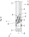
- Fig. 12 is an explanatory diagram illustrating a configuration of a light irradiation device 2E according to the sixth embodiment.
- a light irradiation system according to the sixth embodiment includes the catheter 1 explained in the first embodiment and the light irradiation device 2E illustrated in Fig. 12 .
- the light irradiation device 2E does not include the resin member 270 explained in the first embodiment, and a portion inside the shaft 210, where the optical fiber 250 and the holding member 260 are not accommodated, is a void.
- the configuration of the light irradiation device 2E can be modified in various ways, and the light irradiation device 2E need not include the resin member 270, and may include another reinforcing member in place of the resin member 270.
- a braided body or a coil body can be employed as another reinforcing member.
- Such a reinforcing member may be disposed inside the shaft 210 or embedded in a thick-walled portion of the shaft 210.
- the light irradiation system according to the sixth embodiment as described above makes it possible to exhibit an effect similar to that in the first embodiment described above.
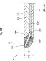
- Fig. 13 is an explanatory diagram illustrating a configuration of a light irradiation device 2F according to a seventh embodiment.
- a light irradiation system according to the seventh embodiment includes the catheter 1 explained in the first embodiment and the light irradiation device 2F illustrated in Fig. 13 .
- the light irradiation device 2F does not have the distal tip 220, and includes an optical fiber 250F instead of an optical fiber 250, and includes an optical fiber 250F instead of the optical fiber 250, and a holding member 260F instead of the holding member 260.
- the optical fiber 250F is arranged such that a part of the distal end side of the curved part 251 protrudes from the distal end of the shaft 210.
- the protruding length of the curved part 251 can be arbitrarily determined.
- the holding member 260F covers the periphery of the curved part 251 protruding from the shaft 210. In other words, the holding member 260F covers the entire surface in the circumferential direction of the curved part 251 protruding from the shaft 210.
- the holding member 260F is shaped such that the diameter gradually decreases from the proximal end side toward the distal end side and the distal end portion is rounded.
- the shape of the holding member 260F with the decreasing diameter is asymmetric with respect to the axis O in the cross section illustrated in Fig. 13 .
- the largest outer diameter of the holding member 260F is equal to the outer diameter ⁇ 3 of the shaft 210 (in other words, the outer diameter ⁇ 3 of the light irradiation device 2F.
- a material and a refractive index of the holding member 260F are the same as those in the first embodiment.
- the configuration of the light irradiation device 2F can be modified in various ways, and the light irradiation device 2F may be configured such that the curved part 251 of the optical fiber 250F protrudes from the shaft 210, and the holding member 260F that covers the periphery of the protruding curved part 251 is further provided.
- the shape of the holding member 260F can be arbitrarily changed.
- the holding member 260F need not cover the entire periphery of the curved part 251 protruding from the shaft 210, and may cover at least a part of the curved part 251.
- the light irradiation system according to the seventh embodiment as described above makes it possible to exhibit an effect similar to that in the first embodiment described above.
- a part on the distal end side of the curved part 251, i.e. the distal end of the optical fiber 250F is protruded from the distal end of the shaft 210 (hollow shaft), so that the light LT emitted from the distal end of the optical fiber 250F can be prevented from being blocked by the shaft 210.
- the holding member 260F covers the periphery of the protruding curved part 251, the periphery of the protruding curved part 251 can be protected.
- FIG. 14 is an explanatory diagram illustrating a configuration of a light irradiation device 2G according to the eighth embodiment.
- Alight irradiation system according to the eighth embodiment includes the catheter 1 explained in the first embodiment and the light irradiation device 2G illustrated in Fig. 14 .
- the light irradiation device 2G has a holding member 260G having a shape different from that in the seventh embodiment, in the configuration in which the curved part 251 of the optical fiber 250F explained in the seventh embodiment protrudes from the shaft 210.
- the holding member 260G covers the periphery (entire surface in the circumferential direction) of the curved part 251 protruding from the shaft 210.
- the holding member 260G is an almost columnar member having a substantially constant outer diameter, and the outer diameter of the holding member 260G is substantially the same as the outer diameter ⁇ 3 of the shaft 210.
- the holding member 260G is joined to the distal end portion of the shaft 210.
- any joining agent such as an epoxy adhesive can be used.
- the configuration of the light irradiation device 2G can be modified in various ways, and may include the holding member 260G having a different shape from that in the seventh embodiment. Also, the light irradiation system according to the eighth embodiment as described above makes it possible to exhibit an effect similar to those in the first and seventh embodiments described above.
- FIG. 15 is an explanatory diagram illustrating a configuration of a light irradiation device 2H according to the ninth embodiment.
- a light irradiation system according to the ninth embodiment includes the catheter 1 explained in the first embodiment and the light irradiation device 2H illustrated in Fig. 15 .
- the light irradiation device 2H has a holding member 260H having a shape different from that in the seventh embodiment, in the configuration in which the curved part 251 of the optical fiber 250F explained in the seventh embodiment protrudes from the shaft 210.
- the holding member 260H includes a distal end side holding member 261H and a proximal end side holding member 262H.
- the distal end side holding member 261H is disposed on the distal end of the light irradiation device 2H to cover the distal periphery (entire surface in the circumferential direction) of the curved part 251 protruding from the shaft 210.
- the proximal end side holding member 262H is disposed between the distal end side holding member 261H and the shaft 210 to cover the proximal periphery (entire surface in the circumferential direction) of the curved part 251 protruding from the shaft 210.
- the distal end side holding member 261H and the proximal end side holding member 262H are both an almost columnar member having a substantially constant outer diameter.
- the outer diameter of the distal end side holding member 261H and the outer diameter of the proximal end side holding member 262H are both substantially equal to the outer diameter ⁇ 3 of the shaft 210.
- the configuration of the light irradiation device 2H can be modified in various ways, and may include the holding member 260H having a different shape from that in the seventh embodiment. Also, the light irradiation system according to the ninth embodiment as described above makes it possible to exhibit an effect similar to those in the first and seventh embodiments described above.
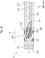
- FIG. 16 is an explanatory diagram illustrating a configuration of a light irradiation device 21 according to the tenth embodiment.
- a light irradiation system according to the tenth embodiment includes the catheter 1 explained in the first embodiment and the light irradiation device 21 illustrated in Fig. 16 .
- the light irradiation device 21 has a shaft 2101 instead of the shaft 210, an optical fiber 250I instead of the optical fiber 250, and a light irradiation portion 2391 instead of the light irradiation portion 239.
- the shaft 210I has a hollow and almost cylindrical shape in which both a distal end portion and a proximal end portion are opened. Unlike the shaft 210 according to the first embodiment, the shaft 2101 has no opening for exposing the distal end of the optical fiber 250I. A portion of the shaft 210I, on which the distal end of the optical fiber 250I abuts, is made of a light transmissive resin, and configured to allow transmission of the laser light LT. Similarly to the optical fiber 250 according to the first embodiment, the optical fiber 250I has the curved part 251 where the optical fiber 250I is curved in the + Y-axis direction, on the distal end portion.
- the optical fiber 250I is arranged such that its distal end (distal end surface) abuts on the inner peripheral surface of the shaft 2101.
- the light LT emitted from the core 250c exposed on the distal end of the optical fiber 250I is transmitted through the shaft 210I and emitted to the outside.
- a part of the shaft 210I functionally serves as the light irradiation portion 2391.
- the configuration of the light irradiation device 21 can be modified in various ways, and the distal end of the optical fiber 250I need not be disposed so as to be exposed on the outer peripheral surface of the shaft 210I.
- a portion of the shaft 210I, on which the distal end of the optical fiber 250I abuts, may have a thickness smaller than of the other portion to allow transmission of the light LT.
- a resin body or a light reflecting mirror for transmission, refraction, and amplification of the light LT may be disposed on the portion of the shaft 210I, on which the distal end of the optical fiber 250I abuts.
- the whole of the shaft 2101 may be formed of the light transmissive resin.
- the light irradiation system according to the tenth embodiment as described above makes it possible to exhibit an effect similar to that in the first embodiment described above.
- Fig. 17 is an explanatory diagram illustrating a configuration of a light irradiation system according to the eleventh embodiment.
- the light irradiation system according to the eleventh embodiment includes the catheter 1 explained in the first embodiment and a light irradiation device 2J illustrated in Fig. 17 .
- the light irradiation device 2J does not have the shaft 210, the distal tip 220, and the connector 240 explained in the first embodiment, and is composed of an optical fiber 250J and a holding member 260J.
- a configuration of the optical fiber 250J is the same as of the optical fiber 250 explained in the first embodiment
- a configuration of the holding member 260J is the same as of the holding member 260 explained in the first embodiment.
- the configuration of the light irradiation device 2J can be modified in various ways, and need not include at least a part of each of the shaft 210, the distal tip 220, and the connector 240.
- the light irradiation system according to the eleventh embodiment as described above makes it possible to exhibit an effect similar to that in the first embodiment described above.
- the configuration of the light irradiation device 2J according to the eleventh embodiment can be simplified, so that the light irradiation device 2J can be easily manufactured and a manufacturing cost of the light irradiation device 2J can be reduced.
- the diameter of the light irradiation device 2J can be decreased, device delivery from a forceps port of a small diameter endoscope such as an oral endoscope or a nasal endoscope becomes possible.
- the configurations of the catheter 1, and the light irradiation devices 2, and 2A to 2J have been described.
- the configurations of the catheter 1 and the light irradiation device 2 can be modified in various ways.
- the light irradiation system may be constituted by only the light irradiation device 2 without the catheter 1.
- a reinforcing layer formed of a braided body or a coil body may be embedded in the shaft 110 of the catheter 1 and the shaft 210 of the light irradiation device 2.
- a coating formed of a hydrophilic or hydrophobic resin may be applied to the outer surface of the catheter 1 and the outer surface of the light irradiation device 2.
- the slidability of the catheter 1 in the living body lumen can be improved.
- the slidability of the light irradiation device 2 in the lumen 110L of the catheter 1 can be improved.
- the outer surface of the catheter 1 or the outer surface of the light irradiation device 2 may be coated with an antithrombotic material such as heparin. This makes it possible to suppress a decrease in laser output due to thrombus adhesion to the inner and outer surfaces of the catheter 1 and the outer surface of the light irradiation device 2 caused by the irradiation with the emission light (laser light) LT.
- the catheter 1 may include an expansion portion expandable in a radial direction (YZ-direction).
- a balloon formed of a flexible thin film or a mesh body having wires arranged in a mesh shape can be used as the expansion portion.
- the expansion portion may be provided on at least one of the distal end side of the light transmitting portion 139 and the proximal end side of the light transmitting portion 139 in the shaft 110.
- the catheter 1 may be configured as a multi-lumen catheter including a plurality of lumens different from the lumen 110L.
- the light irradiation device 2 may be configured as a multi-lumen catheter including a separate lumen different from the lumen 210L into which the first optical fiber 250 is inserted.
- the shaft 210 can be made using a hollow member having a substantially cylindrical shape, and the distal tip 220 can be provided with a through-hole extending along the direction of the axis O.
- the inner surface of the distal tip 120 of the catheter 1 and the outer surface of the distal tip 220 of the light irradiation device 2 may be formed of a magnetic material and may be configured to attract each other.
- a state where the light irradiation device 2 is inserted into the catheter 1 and the distal tip 220 is pressed against the distal tip 120 can be easily maintained.
- the shape of the curved part 251 for allowing the distal end of the optical fiber 250 to intersect with the long axial direction of the light irradiation device 2 is not limited to the shape illustrated in the figures, and any shape can be adopted.
- the optical fiber 250 may have a separate curved part different from the curved part 251 for allowing the distal end of the optical fiber 250 to intersect with the long axial direction of the light irradiation device 2.
- This curved part can be disposed e.g. on the proximal end side of the curved part 251.
- the shape of the curved part can be arbitrarily determined and may be e.g. a spiral shape, a wave shape, or a bellows shape, along the inner peripheral surface of the shaft 210.
- longitudinal ranges (axis O direction) of the holding member 260 arranged adjacent to the periphery of the curved part 251, the inner holding member arranged adjacent to the inner peripheral side of the curved part 251, and the outer holding member arranged adjacent to the outer peripheral side of the curved part 251 can be arbitrarily determined.
- the outer holding member arranged adjacent to the outer peripheral side of the curved part 251 may be disposed up to the distal end (boundary surface between the shaft 210 and the distal tip 220) of the shaft 210.
- the light irradiation device 2 may include only the outer holding member arranged adjacent to the outer peripheral side of the curved part 251 without including the inner holding member arranged adjacent to the inner peripheral side of the curved part 251.
- the outer holding member arranged adjacent to the outer peripheral side of the curved part 251 may include a first outer holding member disposed on the distal end side and a second outer holding member disposed on the proximal end side.
- the outer holding member arranged adjacent to the outer peripheral side of the curved part 251 may include three or more outer holding members.
- the configurations of the light transmitting portion 139, and the light irradiation portions 239 and 2391 have been described.
- the configurations of the light transmitting portion 139 and the light irradiation portion 239 can be modified in various ways.
- the light transmitting portion 139 may be formed of a radiopaque material, to integrally form the light transmitting portion 139 and the first marker portions 131 and 132.
- at least the distal end portion (light irradiation portion 239) of the clad 250cl may be formed of a radiopaque material to integrally form the light irradiation portion 239 and the second marker portions 231 and 232.
- the light transmitting portion 139 may be formed by thinning a part of the shaft 110.
- at least one side of the light transmitting portion 139 may be formed as a notch (through hole that communicates between the inside and outside of the shaft) formed on the shaft 110.
- the light transmitting portion 139 can be easily formed.
- the range in the axis O direction (X-axis direction) and the range in the circumferential direction (YZ-axis direction), where the light transmitting portion 139 is disposed can be arbitrarily changed.
- the light transmitting portion 139 may be disposed over a wide range in the axis O direction.
- the catheter 1 may further include a separate marker portion disposed at any position, such as the distal end side and the proximal end side of the light transmitting portion 139.
- the light irradiation device 2 may further include a separate marker portion disposed at any position, such as the distal end side and the proximal end side of the light transmitting portion 239.
- the shapes of the marker portions of the catheter 1 and the light irradiation device 2 can be arbitrarily determined, and may be a shape extending over the whole or a part of the circumferential direction (YZ direction), a shape extending in the axis O direction (X-axis direction), or a shape surrounding the periphery of the shaft.
- the distal tip 120 of the catheter 1 or the distal tip 220 of the light irradiation device 2 may be configured as the marker portions.
- the configurations of the catheter 1, and the light irradiation devices 2, and 2A to 2J according to the first to eleventh embodiments, and the configurations of the catheter 1, and the light irradiation devices 2, and 2A to 2J according to the first to third modifications may be combined as appropriate.
- the configuration explained in the sixth embodiment (configuration not including the resin member 270) may include the holding member 260 explained in the second to fifth embodiments or the seventh to ninth embodiments.
- the configuration explained in the tenth embodiment (configuration in which the distal end of the optical fiber 250 abuts on the inner peripheral surface of the shaft 210) may include the holding member 260 explained in the second to fifth embodiments or the seventh to ninth embodiments.
- the configuration explained in the eleventh embodiment (configuration not including the shaft 210, the distal tip 220, and the connector 240) may include the holding member 260 explained in the second to fifth embodiments or the seventh to ninth embodiments.
Landscapes
- Health & Medical Sciences (AREA)
- Physics & Mathematics (AREA)
- Life Sciences & Earth Sciences (AREA)
- Biomedical Technology (AREA)
- Engineering & Computer Science (AREA)
- Optics & Photonics (AREA)
- Animal Behavior & Ethology (AREA)
- General Health & Medical Sciences (AREA)
- Nuclear Medicine, Radiotherapy & Molecular Imaging (AREA)
- Veterinary Medicine (AREA)
- Public Health (AREA)
- General Physics & Mathematics (AREA)
- Surgery (AREA)
- Radiology & Medical Imaging (AREA)
- Pathology (AREA)
- Astronomy & Astrophysics (AREA)
- Biophysics (AREA)
- Electromagnetism (AREA)
- Otolaryngology (AREA)
- Heart & Thoracic Surgery (AREA)
- Medical Informatics (AREA)
- Molecular Biology (AREA)
- Radiation-Therapy Devices (AREA)
- Laser Surgery Devices (AREA)
- Surgical Instruments (AREA)
Applications Claiming Priority (2)
| Application Number | Priority Date | Filing Date | Title |
|---|---|---|---|
| JP2019190447A JP7308123B2 (ja) | 2019-10-17 | 2019-10-17 | 光照射デバイス、及び、光照射システム |
| PCT/JP2020/030964 WO2021075140A1 (ja) | 2019-10-17 | 2020-08-17 | 光照射デバイス、及び、光照射システム |
Publications (2)
| Publication Number | Publication Date |
|---|---|
| EP4046586A1 true EP4046586A1 (de) | 2022-08-24 |
| EP4046586A4 EP4046586A4 (de) | 2023-11-15 |
Family
ID=75537798
Family Applications (1)
| Application Number | Title | Priority Date | Filing Date |
|---|---|---|---|
| EP20876373.0A Withdrawn EP4046586A4 (de) | 2019-10-17 | 2020-08-17 | Lichtemittierende vorrichtung und lichtemittierendes system |
Country Status (5)
| Country | Link |
|---|---|
| US (1) | US11874455B2 (de) |
| EP (1) | EP4046586A4 (de) |
| JP (1) | JP7308123B2 (de) |
| CN (1) | CN114514051A (de) |
| WO (1) | WO2021075140A1 (de) |
Families Citing this family (4)
| Publication number | Priority date | Publication date | Assignee | Title |
|---|---|---|---|---|
| JP7326021B2 (ja) * | 2019-05-16 | 2023-08-15 | 朝日インテック株式会社 | 光照射デバイス、及び、光照射システム |
| DE112023003925T5 (de) * | 2022-09-21 | 2025-07-03 | Furukawa Electric Co., Ltd. | Optische fasersonde |
| CN119300886A (zh) | 2023-03-03 | 2025-01-10 | 益明医疗株式会社 | 光照射设备和光照射系统 |
| JP7444519B1 (ja) * | 2023-03-03 | 2024-03-06 | イルミメディカル株式会社 | 光照射デバイスおよび光照射システム |
Family Cites Families (18)
| Publication number | Priority date | Publication date | Assignee | Title |
|---|---|---|---|---|
| US3123066A (en) * | 1964-03-03 | brumley | ||
| US4747405A (en) * | 1984-03-01 | 1988-05-31 | Vaser, Inc. | Angioplasty catheter |
| US4669467A (en) * | 1985-03-22 | 1987-06-02 | Massachusetts Institute Of Technology | Mode mixer for a laser catheter |
| JPH0442817Y2 (de) | 1986-05-15 | 1992-10-09 | ||
| US4852567A (en) * | 1988-01-21 | 1989-08-01 | C. R. Bard, Inc. | Laser tipped catheter |
| JP2779825B2 (ja) * | 1989-02-15 | 1998-07-23 | 則雄 大工園 | レーザ光出射装置 |
| JP3467268B2 (ja) * | 1990-08-06 | 2003-11-17 | アキュレイズ,インコーポレイテッド | ファイバー光学によるレーザーカテーテル |
| US5495541A (en) * | 1994-04-19 | 1996-02-27 | Murray; Steven C. | Optical delivery device with high numerical aperture curved waveguide |
| DE60025087D1 (de) | 1999-07-30 | 2006-02-02 | Terumo Corp | Laserbestrahlungsgerät |
| JP2001037892A (ja) | 1999-07-30 | 2001-02-13 | Terumo Corp | レーザ照射装置 |
| JP4388647B2 (ja) * | 1999-10-27 | 2009-12-24 | テルモ株式会社 | レーザ照射装置 |
| WO2005007216A2 (en) | 2003-07-09 | 2005-01-27 | Light Sciences Corporaion | Device for distal protection and treatment of blood vessels |
| JP2005237827A (ja) | 2004-02-27 | 2005-09-08 | Terumo Corp | 治療用カテーテルおよび治療装置 |
| US20070073277A1 (en) | 2005-09-16 | 2007-03-29 | Medicalcv, Inc. | Controlled guided ablation treatment |
| US8657812B2 (en) | 2008-05-19 | 2014-02-25 | Boston Scientific Scimed, Inc. | Side-firing laser fiber with internal bent fiber and related methods |
| CA2841120C (en) | 2011-07-11 | 2020-10-27 | The United States Of America, As Represented By The Secretary, Department Of Health And Human Services | Antibody-ir700 conjugates for photodynamic therapy |
| KR20160029270A (ko) * | 2014-09-05 | 2016-03-15 | 민규석 | 광섬유 어셈블리 |
| JP2018000867A (ja) | 2016-07-08 | 2018-01-11 | 株式会社アライ・メッドフォトン研究所 | カテーテルチューブ |
-
2019
- 2019-10-17 JP JP2019190447A patent/JP7308123B2/ja active Active
-
2020
- 2020-08-17 WO PCT/JP2020/030964 patent/WO2021075140A1/ja not_active Ceased
- 2020-08-17 CN CN202080070103.9A patent/CN114514051A/zh not_active Withdrawn
- 2020-08-17 EP EP20876373.0A patent/EP4046586A4/de not_active Withdrawn
-
2022
- 2022-04-06 US US17/714,637 patent/US11874455B2/en active Active
Also Published As
| Publication number | Publication date |
|---|---|
| JP7308123B2 (ja) | 2023-07-13 |
| JP2021065256A (ja) | 2021-04-30 |
| EP4046586A4 (de) | 2023-11-15 |
| WO2021075140A1 (ja) | 2021-04-22 |
| CN114514051A (zh) | 2022-05-17 |
| US20220229282A1 (en) | 2022-07-21 |
| US11874455B2 (en) | 2024-01-16 |
Similar Documents
| Publication | Publication Date | Title |
|---|---|---|
| US11874455B2 (en) | Light irradiation device and light irradiation system | |
| US12343555B2 (en) | Light irradiation system, catheter, and light irradiation device | |
| US12257447B2 (en) | Light irradiation device and light irradiation system | |
| US12496459B2 (en) | Light irradiation device and light irradiation system | |
| JP2021090503A (ja) | 光照射デバイス | |
| US12415088B2 (en) | Light irradiation device and light irradiation system | |
| JP7346134B2 (ja) | カテーテル、及び、光照射システム | |
| JP7624650B2 (ja) | 光照射デバイス、及び、光照射システム | |
| JP7741622B2 (ja) | 光照射デバイス、及び、光照射システム | |
| WO2020230519A1 (ja) | 光照射システム、カテーテル、及び、光照射デバイス | |
| WO2021075141A1 (ja) | 光照射デバイス、及び、光照射システム | |
| JP7795318B2 (ja) | 光照射システム | |
| JP2021090504A (ja) | 光照射デバイス | |
| JP2021083661A (ja) | 光照射デバイス |
Legal Events
| Date | Code | Title | Description |
|---|---|---|---|
| STAA | Information on the status of an ep patent application or granted ep patent |
Free format text: STATUS: THE INTERNATIONAL PUBLICATION HAS BEEN MADE |
|
| PUAI | Public reference made under article 153(3) epc to a published international application that has entered the european phase |
Free format text: ORIGINAL CODE: 0009012 |
|
| STAA | Information on the status of an ep patent application or granted ep patent |
Free format text: STATUS: REQUEST FOR EXAMINATION WAS MADE |
|
| 17P | Request for examination filed |
Effective date: 20220411 |
|
| AK | Designated contracting states |
Kind code of ref document: A1 Designated state(s): AL AT BE BG CH CY CZ DE DK EE ES FI FR GB GR HR HU IE IS IT LI LT LU LV MC MK MT NL NO PL PT RO RS SE SI SK SM TR |
|
| DAV | Request for validation of the european patent (deleted) | ||
| DAX | Request for extension of the european patent (deleted) | ||
| A4 | Supplementary search report drawn up and despatched |
Effective date: 20231012 |
|
| RIC1 | Information provided on ipc code assigned before grant |
Ipc: F21V 8/00 20060101ALN20231006BHEP Ipc: G02B 23/24 20060101ALI20231006BHEP Ipc: G02B 6/36 20060101ALI20231006BHEP Ipc: A61B 18/18 20060101ALI20231006BHEP Ipc: A61N 5/067 20060101ALI20231006BHEP Ipc: A61N 5/06 20060101ALI20231006BHEP Ipc: A61B 18/24 20060101AFI20231006BHEP |
|
| STAA | Information on the status of an ep patent application or granted ep patent |
Free format text: STATUS: EXAMINATION IS IN PROGRESS |
|
| 17Q | First examination report despatched |
Effective date: 20250623 |
|
| STAA | Information on the status of an ep patent application or granted ep patent |
Free format text: STATUS: THE APPLICATION HAS BEEN WITHDRAWN |
|
| 18W | Application withdrawn |
Effective date: 20250825 |