EP4046670B1 - Spülanordnung - Google Patents
Spülanordnung Download PDFInfo
- Publication number
- EP4046670B1 EP4046670B1 EP22157244.9A EP22157244A EP4046670B1 EP 4046670 B1 EP4046670 B1 EP 4046670B1 EP 22157244 A EP22157244 A EP 22157244A EP 4046670 B1 EP4046670 B1 EP 4046670B1
- Authority
- EP
- European Patent Office
- Prior art keywords
- attachment
- arrangement according
- flushing
- flushing arrangement
- previous
- Prior art date
- Legal status (The legal status is an assumption and is not a legal conclusion. Google has not performed a legal analysis and makes no representation as to the accuracy of the status listed.)
- Active
Links
Images



Classifications
-
- A—HUMAN NECESSITIES
- A61—MEDICAL OR VETERINARY SCIENCE; HYGIENE
- A61M—DEVICES FOR INTRODUCING MEDIA INTO, OR ONTO, THE BODY; DEVICES FOR TRANSDUCING BODY MEDIA OR FOR TAKING MEDIA FROM THE BODY; DEVICES FOR PRODUCING OR ENDING SLEEP OR STUPOR
- A61M1/00—Suction or pumping devices for medical purposes; Devices for carrying-off, for treatment of, or for carrying-over, body-liquids; Drainage systems
- A61M1/71—Suction drainage systems
- A61M1/77—Suction-irrigation systems
-
- A—HUMAN NECESSITIES
- A61—MEDICAL OR VETERINARY SCIENCE; HYGIENE
- A61M—DEVICES FOR INTRODUCING MEDIA INTO, OR ONTO, THE BODY; DEVICES FOR TRANSDUCING BODY MEDIA OR FOR TAKING MEDIA FROM THE BODY; DEVICES FOR PRODUCING OR ENDING SLEEP OR STUPOR
- A61M1/00—Suction or pumping devices for medical purposes; Devices for carrying-off, for treatment of, or for carrying-over, body-liquids; Drainage systems
- A61M1/84—Drainage tubes; Aspiration tips
- A61M1/85—Drainage tubes; Aspiration tips with gas or fluid supply means, e.g. for supplying rinsing fluids or anticoagulants
-
- A—HUMAN NECESSITIES
- A61—MEDICAL OR VETERINARY SCIENCE; HYGIENE
- A61M—DEVICES FOR INTRODUCING MEDIA INTO, OR ONTO, THE BODY; DEVICES FOR TRANSDUCING BODY MEDIA OR FOR TAKING MEDIA FROM THE BODY; DEVICES FOR PRODUCING OR ENDING SLEEP OR STUPOR
- A61M1/00—Suction or pumping devices for medical purposes; Devices for carrying-off, for treatment of, or for carrying-over, body-liquids; Drainage systems
- A61M1/84—Drainage tubes; Aspiration tips
- A61M1/87—Details of the aspiration tip, not otherwise provided for
-
- A—HUMAN NECESSITIES
- A61—MEDICAL OR VETERINARY SCIENCE; HYGIENE
- A61M—DEVICES FOR INTRODUCING MEDIA INTO, OR ONTO, THE BODY; DEVICES FOR TRANSDUCING BODY MEDIA OR FOR TAKING MEDIA FROM THE BODY; DEVICES FOR PRODUCING OR ENDING SLEEP OR STUPOR
- A61M3/00—Medical syringes, e.g. enemata; Irrigators
- A61M3/02—Enemata; Irrigators
- A61M3/0279—Cannula; Nozzles; Tips; their connection means
-
- A—HUMAN NECESSITIES
- A61—MEDICAL OR VETERINARY SCIENCE; HYGIENE
- A61M—DEVICES FOR INTRODUCING MEDIA INTO, OR ONTO, THE BODY; DEVICES FOR TRANSDUCING BODY MEDIA OR FOR TAKING MEDIA FROM THE BODY; DEVICES FOR PRODUCING OR ENDING SLEEP OR STUPOR
- A61M3/00—Medical syringes, e.g. enemata; Irrigators
- A61M3/02—Enemata; Irrigators
- A61M3/0279—Cannula; Nozzles; Tips; their connection means
- A61M3/0283—Cannula; Nozzles; Tips; their connection means with at least two inner passageways, a first one for irrigating and a second for evacuating
-
- A—HUMAN NECESSITIES
- A61—MEDICAL OR VETERINARY SCIENCE; HYGIENE
- A61M—DEVICES FOR INTRODUCING MEDIA INTO, OR ONTO, THE BODY; DEVICES FOR TRANSDUCING BODY MEDIA OR FOR TAKING MEDIA FROM THE BODY; DEVICES FOR PRODUCING OR ENDING SLEEP OR STUPOR
- A61M1/00—Suction or pumping devices for medical purposes; Devices for carrying-off, for treatment of, or for carrying-over, body-liquids; Drainage systems
- A61M1/84—Drainage tubes; Aspiration tips
- A61M1/86—Connectors between drainage tube and handpiece, e.g. drainage tubes detachable from handpiece
-
- A—HUMAN NECESSITIES
- A61—MEDICAL OR VETERINARY SCIENCE; HYGIENE
- A61M—DEVICES FOR INTRODUCING MEDIA INTO, OR ONTO, THE BODY; DEVICES FOR TRANSDUCING BODY MEDIA OR FOR TAKING MEDIA FROM THE BODY; DEVICES FOR PRODUCING OR ENDING SLEEP OR STUPOR
- A61M2206/00—Characteristics of a physical parameter; associated device therefor
- A61M2206/10—Flow characteristics
- A61M2206/16—Rotating swirling helical flow, e.g. by tangential inflows
-
- A—HUMAN NECESSITIES
- A61—MEDICAL OR VETERINARY SCIENCE; HYGIENE
- A61M—DEVICES FOR INTRODUCING MEDIA INTO, OR ONTO, THE BODY; DEVICES FOR TRANSDUCING BODY MEDIA OR FOR TAKING MEDIA FROM THE BODY; DEVICES FOR PRODUCING OR ENDING SLEEP OR STUPOR
- A61M2210/00—Anatomical parts of the body
- A61M2210/02—Bones
Definitions
- the invention relates to a rinsing arrangement for rinsing systems for cleaning surgical wounds by means of rinsing fluid
- a rinsing arrangement for rinsing systems for cleaning surgical wounds by means of rinsing fluid comprising an outer tube in which an inner tube is arranged, wherein an annular gap is formed between the outer tube and the inner tube at least in sections, and an attachment is provided on the free end of the outer tube, wherein outlet openings for the rinsing fluid are formed in the attachment, which are designed such that the rinsing fluid exits at an angle ⁇ and thus obliquely to the longitudinal center line of the tubes.
- Irrigation systems (so-called lavage systems) of the type considered here are used to clean surgical wounds in order to flush necrotic tissue, bacteria and foreign material out of the wound.
- Such rinsing systems are used in particular in operations on bones, such as when inserting artificial joints, to flush out residues that arise during the operation. This is intended to avoid complications after the operation and speed up healing, especially since residues can impair the durability of the artificial joint and lead to infections in the area of the bone.
- the rinsing should be thorough but at the same time gentle.
- the flushing systems produce a laminar or pulsating jet that passes through a pipe to a nozzle and exits the system through the nozzle.
- the liquid is mainly sterile saline solution or an aqueous solution that can also contain pharmaceutically active substances.
- the liquid contaminated with residues is sucked out by special suction devices via a second channel.
- the suction devices have a funnel shape and can be part of the flushing system.
- the suction devices can also be designed in the form of a separate device.
- An essential criterion for the quality of the irrigation, in addition to the irrigation volume, is the pressure with which the fluid is applied to the bone, the spongiosa or the If the jet is too strong, this can lead to damage to the bone or similar. Harmful components can then be pushed deeper into the bone instead of being flushed out.
- the jet emerges from the rinsing system in a straight line, i.e. along the imaginary extension of the longitudinal center line of the nozzle. When used as intended, it therefore hits the bone or tissue surface to be rinsed vertically. This results in a very small cleaning area. In addition, the jet hits the bone or tissue surface with maximum pressure, which can lead to unwanted damage to the surfaces.
- flushing systems For flushing tubular cavities of organs (so-called lumens), flushing systems are used in which a baffle plate is arranged in front of the nozzle, which deflects the flushing liquid at a right angle after it exits the nozzle. so that the wall formed by the bone or spongiosa can be rinsed. The jet therefore also hits the bone or tissue surface to be rinsed vertically.
- suction takes place via an annular gap that surrounds the nozzle, which can lead to the blockage mentioned above.
- healthy tissue can be damaged by the sharp-edged outer tube when the system is inserted.
- Flushing devices are known in which the rinsing liquid exits the device at an angle and in which the rinsing liquid is sucked off in the center.
- the invention is based on the object of creating a rinsing system with which, on the one hand, the cleaning area is increased and, on the other hand, gentle rinsing is possible. According to the invention, this object is achieved with the features of patent claim 1.
- the invention creates a flushing system that increases the cleaning area and prevents the suction pipe from becoming clogged.
- the oblique impact of the flushing jet on the surface causes the material to be removed to be removed and penetrated, and the coating to be removed is removed more gently. At the same time, the material to be removed is flushed in the direction of the central suction.
- the outlet openings formed in the area of a constriction facing away from the tubes and immediately adjacent to the section lead to a jet of rinsing fluid directed towards the center of the wound. This improves the suction of the fluid from the wound because the suction takes place through the inner tube in the center of the rinsing arrangement. In addition, this design ensures that the jet hits the area to be rinsed at an angle.
- the free end of the attachment is formed by a funnel-shaped section. This design ensures reliable suction of the Irrigation fluid. At the same time, this creates a kind of shielding of the wound to be rinsed, which prevents the fluid from being released in an uncontrolled manner.
- the attachment is designed like a cap and is preferably rounded on the outside. This covers the sharp edges of the tube and protects the bone tissue when it is inserted into the lumina.
- the attachment has bristles on its circumference. This improves the cleaning of deep lumens, for example when cleaning bone cement or residues of special medical adhesives, which are often used when inserting hip prostheses.
- the bristles enable mechanical cleaning of the surface, similar to a brush.
- the bristles are most preferably arranged in a helix manner around the circumference of the attachment.
- the rows of bristles therefore follow a spiral around the tube.
- the brushes have a linear and parallel arrangement of the rows of bristles to the central axis. This makes it necessary to move the inserted tube both axially and radially in the lumen in order to reach all areas of the surface to be cleaned. Since the area to be cleaned is not visible to the user, the cleaning result cannot be checked.
- the helix arrangement eliminates this problem. Only one axial insertion of the rinsing assembly is required.
- the arrangement of the bristles means that every area can be reached and mechanically brushed when inserted.
- the bristles are conical.
- the conical design of the bristles creates a bending line in order to achieve sufficient stiffness of the bristles while simultaneously cleaning the surface as gently as possible.
- Each rinsing arrangement shown in the exemplary embodiments are intended for rinsing systems for cleaning surgical wounds using rinsing fluid.
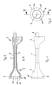
- Each rinsing arrangement comprises an outer tube 1 in which an inner tube 2 is arranged.
- An annular gap 3 is formed in sections between the outer tube 1 and the inner tube 2.
- the annular gap can also extend over the entire length of the outer tube 1 and the inner tube 2.
- an adapter piece 4 is arranged for connection to a drive and actuation unit (not shown), as is known from the prior art.
- An attachment 5 is provided at the end of the outer tube 1 facing away from the adapter piece 4.
- the adapter piece 4 covers one end of the outer tube 1 in a liquid-tight manner with its end facing the attachment 5.
- the design of the adapter piece 4 widens in the direction of the side facing away from the attachment 5.
- An insert 6 is arranged in the adapter piece, which has a pump holder 7 and a pipe section 8.
- the end of the inner tube 2 facing away from the adapter piece 4 is received on one side of the pipe section 8.
- the other side of the pipe section 8 is intended for connecting another hose.
- a stable pump protrudes into the pump holder 7, which is sealed against the pump holder 7 by means of an O-ring and which supplies the flushing liquid; a suction hose is connected to the pipe section 8 to use the flushing arrangement, which drains the contaminated flushing liquid.
- This arrangement means that the flushing liquid is supplied to the attachment 5 through the annular gap 3 and the contaminated flushing liquid is drained through the inner pipe 2.
- the attachment 5 is designed differently, as can be seen from the figures.
- the attachment 5 is essentially bell-shaped.
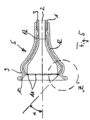
- the attachment 5 In its area facing away from the adapter piece 4, the attachment 5 has a constriction 9, which is followed by a funnel-shaped section 10, which forms the free end of the attachment 5.
- outlet openings 11 for the rinsing liquid are formed in the attachment 5, adjacent to one another.
- the outlet openings 11 form the end of channels 12 which are formed in the attachment 5 and which are connected to the annular gap 3 at their ends facing away from the outlet openings 11.
- the outlet openings 11 are clearly designed in such a way that the flushing liquid exits at an angle ⁇ and thus obliquely to the longitudinal center line of the flushing arrangement or the outer tube 1 and the inner tube 2 (cf. Figures 5 and 6 ).
- oblique means that the angle ⁇ deviates from the longitudinal center line of the flushing arrangement or the line running at right angles thereto at an acute or obtuse angle.
- the angle ⁇ is preferably between 5° and 85° to the longitudinal center line of the flushing arrangement.
- the rinsing liquid also exits the outlet openings 11 at an angle ⁇ .
- the rinsing liquid also exits the attachment 5 at an angle ⁇ to the radial line due to a corresponding design of the outlet openings 11, as shown by the arrows in the left half of Figure 7 This causes the rinsing liquid to rotate, which creates a kind of turbulence, which further improves the rinsing result.
- the attachment 5 is designed like a cap.
- the attachment 5 is clearly rounded on the outside. It is provided with webs 13, the wall thickness of which corresponds to the height of the annular gap 3. In the assembled state, the webs 13 are accommodated in the annular gap 3. In its center, the attachment 5 is penetrated by an opening 14, which is aligned coaxially to the inner tube 2 and whose diameter essentially corresponds to the inner diameter of the inner tube 2. The opening 14 therefore allows the contaminated rinsing liquid is sucked to the inner pipe 2 and drained away through it.
- Outlet openings 11 for the rinsing liquid are formed in the attachment 5.
- the outlet openings 11 are provided with an impact surface 15 which is designed in the manner of an outward-facing circular section.
- the circular section extends over an area of approximately 25°. It can be seen that the outermost end of the circular section of the impact surface 15 is neither parallel nor perpendicular to the longitudinal center line of the rinsing arrangement or the outer tube 1 and the inner tube 2. Consequently, the rinsing liquid emerges at an angle, namely at an angle ⁇ (see Figure 11).
- a type of comb can be provided on the opening 14, which can fulfill a filtering function. This can prevent the opening 14 or the inner tube 2 from becoming blocked.
- the attachment 5 is essentially hollow-cylindrical. It is pushed onto the end of the outer tube 1 with its end facing the adapter piece 4 and surrounds the area of the inner tube 2 that protrudes beyond the outer tube 1. At its end facing away from the adapter piece 4, the attachment 5 rests on the inner tube 2. In this area, the attachment 5 is also penetrated by an opening 14. The diameter of the opening 14 essentially corresponds to the inner diameter of the inner tube 2. Consequently, in this embodiment, too, the contaminated rinsing liquid is sucked through the opening 14 to the inner tube 2 and discharged through it.
- the inner diameter of the attachment 5 corresponds essentially to the inner diameter of the outer tube 1. Consequently, an annular gap 16 is formed between the inner tube 2 and the attachment 5, which is a continuation of the annular gap 3.
- the attachment 5 is provided with outlet openings 11 which are designed like windows. In the exemplary embodiment, four outlet openings 11 are formed, which are arranged all around the attachment 5. A different number of outlet openings 11 is possible.
- the outlet openings 11 can also be arranged at other locations on the attachment 5. It is also possible to provide several rings of outlet openings 11. In the outlet openings 11, impact surfaces 15 are provided which are neither parallel nor aligned at right angles to the longitudinal center line of the flushing arrangement or the outer tube 1 and the inner tube 2.
- the flushing liquid exits the attachment 5 at an angle, namely at the angle ⁇ .
- the impact surfaces 15 it is also possible to design the impact surfaces 15 in such a way that the rinsing liquid exits the outlet openings 11 from the attachment 5 at an angle ⁇ to the radial line.
- the rinsing liquid can also be swirled in the manner of a rotation, which improves the rinsing effect.
- the attachment 5 has bristles 18 on its circumference.
- the bristles are made of the same material as the attachment. They are molded onto the attachment 5.
- the bristles 18 are arranged in rows on the circumference in the manner of a helix. The rows of bristles thus follow a kind of spiral around the attachment 5. They each have two sharp edges 19 and a curve 20.
- the bristles 18 are conical. The arrangement of the bristles on the circumference and the arrangement of the outlet openings between the bristles allow the rinsing liquid to escape between the bristles. Rinsing therefore takes place where the mechanical processing of the surface is also taking place at the same time.
- the flushing arrangement according to the invention makes it possible to allow the flushing liquid to exit at different angles and in different directions and to direct it onto the areas to be flushed.
- the volume and direction of the exiting jet can be influenced by varying the size, cross-section and angle. This makes it possible to adapt the invention to different surfaces.
Landscapes
- Health & Medical Sciences (AREA)
- Heart & Thoracic Surgery (AREA)
- Life Sciences & Earth Sciences (AREA)
- Animal Behavior & Ethology (AREA)
- Engineering & Computer Science (AREA)
- Anesthesiology (AREA)
- Biomedical Technology (AREA)
- Hematology (AREA)
- Veterinary Medicine (AREA)
- Public Health (AREA)
- General Health & Medical Sciences (AREA)
- Vascular Medicine (AREA)
- Surgery (AREA)
- Pulmonology (AREA)
- Oral & Maxillofacial Surgery (AREA)
- Infusion, Injection, And Reservoir Apparatuses (AREA)
Description
- Die Erfindung betrifft eine Spülanordnung für Spülsysteme zur Reinigung von Operationswunden mittels Spülflüssigkeit umfassend ein Außenrohr, in dem ein Innenrohr angeordnet ist, wobei zwischen Außenrohr und Innenrohr mindestens abschnittsweise ein Ringspalt ausgebildet ist, und an dem freien Ende des Außenrohrs ein Aufsatz vorgesehen ist, wobei in dem Aufsatz Austrittsöffnungen für die Spülflüssigkeit ausgebildet sind, die derart gestaltet sind, dass die Spülflüssigkeit unter einem Winkel α und somit schräg zur Längsmittellinie der Rohre austritt.
- Spülsysteme (sog. Lavage-Systeme) der hier betrachteten Art dienen zur Reinigung von Operationswunden, um nekrotisches Gewebe, Bakterien und Fremdmaterial aus der Wunde zu spülen. Insbesondere bei Operationen am Knochen, wie zum Beispiel beim Einsetzen von künstlichen Gelenken, werden solche Spülsysteme eingesetzt, um Rückstände, die bei der Operation entstehen, auszuspülen. Dadurch sollen Komplikationen nach der Operation vermieden und die Heilung beschleunigt werden, zumal Rückstände die Haltbarkeit des künstlichen Gelenks beeinträchtigen und zu Infektionen im Bereich des Knochens führen können. Die Spülung soll dabei gründlich aber gleichzeitig schonend erfolgen.
- Durch die Spülsysteme wird ein laminarer oder pulsierender Strahl erzeugt, der durch ein Rohr zu einer Düse gelangt und durch die Düse aus dem System austritt. Bei der Flüssigkeit handelt es sich überwiegend um sterile Kochsalzlösung oder eine wässrige Lösung, die auch pharmazeutisch wirksame Substanzen enthalten kann. Die mit den Rückständen kontaminierte Flüssigkeit wird durch besondere Sauger über einen zweiten Kanal abgesaugt. Die Sauger haben eine trichterförmige Gestalt und können Bestandteil des Spülsystems sein. Die Sauger können aber auch in Form einer separaten Vorrichtung ausgebildet sein.
- Ein wesentliches Kriterium für die Qualität der Spülung neben dem Spülvolumen ist der Druck, mit dem die Flüssigkeit auf den Knochen, die Spongiosa oder das Gewebe trifft. Ist der Strahl zu fest, kann dies zu einer Schädigung des Knochens o. dgl. führen. Schädigende Bestandteile können dann statt ausgespült tiefer in den Knochen gedrückt werden.
- Bei den Spülsystemen finden unterschiedliche Gestaltungen des Spül- bzw. Absaugrohrs Anwendung. So sind Gestaltungen bekannt, bei denen in dem Absaugrohr koaxial das Spülrohr angeordnet ist (vgl. bspw.
DE 10 2012 000 392 A1 ). Der Spülstrahl tritt folglich in der Mitte aus der Düse aus. Die Spülflüssigkeit wird dabei über den um das Spülrohr herum ausgebildeten Ringspalt aufgesaugt. Aufgrund der geringen Abmessungen weist diese Lösung aber den Nachteil auf, dass der Ringspalt beim Absaugen größerer Mengen an kontaminierter Flüssigkeit verstopfen kann. - Zur Vermeidung dieses Nachteils sind Gestaltungen bekannt, bei denen in dem Spülrohr koaxial das Absaugrohr angeordnet ist (vgl. bspw.
DE 20 2010 011 728 U1 ). Die Düse am Spülrohr umgibt folglich das Absaugrohr. Das Absaugen erfolgt somit zentral in der Mitte des Spül- und Absaugrohrs, wodurch der vorgenannte Nachteil vermieden ist. - Darüber hinaus sind Gestaltungen bekannt, bei denen das Absaugen über ein benachbart und parallel zur Düse ausgerichtetes Rohr erfolgt. Dadurch ist zwar ebenfalls der Gefahr eines Verstopfens entgegengewirkt; gleichzeitig ist aber dem Operateur die Sicht auf die besprühte Stelle versperrt.
- Bei allen bekannten Spülsystemen tritt der Strahl gerade, also entlang der gedachten Verlängerung der Längsmittellinie der Düse aus dem Spülsystem aus. Er trifft daher bei bestimmungsgemäßem Gebrauch senkrecht auf die zu spülende Knochen- oder Gewebefläche. Das hat eine sehr kleine Reinigungsfläche zur Folge. Zudem trifft der Strahl mit maximalem Druck auf die Knochen- oder Gewebefläche, was zu unerwünschten Verletzungen der Flächen führen kann.
- Zum Spülen von röhrenförmigen Hohlräumen von Organen (sog. Lumen) finden Spülsysteme Anwendung, bei denen vor der Düse eine Prallplatte angeordnet ist, die die Spülflüssigkeit nach dem Austritt aus der Düse rechtwinklig umlenkt, so dass die vom Knochen bzw. Spongiosa gebildete Wandung gespült werden kann. Der Strahl trifft daher ebenfalls senkrecht auf die zu spülende Knochen- oder Gewebefläche. Das Absaugen erfolgt auch hier über einen Ringspalt, der die Düse umgibt, was zu dem bereits oben erwähnten Verstopfen führen kann. Hinzu kommt die Gefahr, dass gesundes Gewebe beim Einführen des Systems durch das scharfkantige Außenrohr beschädigt werden kann.
- Aus der
DE 20 2010 011 728 U1 , derCN 103480058 B , derUS 5 460 604 A und derUS 5 464 390 A sind Spülvorrichtungen bekannt, bei denen die Spülflüssigkeit unter einem Winkel aus der Vorrichtung austritt und bei denen das Absaugen der Spülflüssigkeit im Zentrum erfolgt. - Vor diesem Hintergrund liegt der Erfindung die Aufgabe zugrunde, ein Spülsystem zu schaffen, mit dem einerseits die Reinigungsfläche vergrößert ist und andererseits eine schonende Spülung ermöglicht ist. Gemäß der Erfindung wird diese Aufgabe mit den Merkmalen des Patentanspruchs 1 gelöst.
- Mit der Erfindung ist ein Spülsystem geschaffen, mit dem einerseits die Reinigungsfläche vergrößert ist und andererseits ein Verstopfen des Saugrohrs verhindert ist. Durch das schräge Auftreffen des Spülstrahls auf der Oberfläche wird ein Ablösen und Unterwandern erreicht und der abzutragende Belag löst sich schonender ab. Gleichzeitig wird das abzutragende Material in Richtung der zentralen Absaugung gespült.
- Die in dem den Rohren abgewandten Bereich einer Einschnürung und unmittelbar benachbart zu dem Abschnitt ausgebildeten Austrittsöffnungen führen dabei zu einem in das Zentrum der Wunde gerichteten Strahl der Spülflüssigkeit. Dadurch ist das Absaugen der Flüssigkeit aus der Wunde verbessert, weil das Absaugen durch das Innenrohr im Zentrum der Spülanordnung erfolgt. Zudem ist durch diese Ausbildung das Auftreffen des Strahls unter einem Winkel auf den zu spülenden Bereich gewährleistet.
- Das freie Ende des Aufsatzes ist von einem trichterförmigen Abschnitt gebildet. Diese Ausbildung gewährleistet ein zuverlässiges Aufsaugen der Spülflüssigkeit. Gleichzeitig ist dadurch eine Art Abschirmung der zu spülenden Wunde hervorgerufen, die ein unkontrolliertes Ausbringen der Flüssigkeit verhindert.
- In Weiterbildung der Erfindung ist der Aufsatz kappenartig ausgebildet und vorzugsweise außen abgerundet ausgeführt. Dadurch sind die scharfen Kanten des Rohres abgedeckt und das Knochengewebe beim Einschieben in Lumina geschont.
- In Ausgestaltung der Erfindung weist der Aufsatz auf seinem Umfang Borsten auf. Dadurch ist die Reinigung tiefer Lumina verbessert, beispielsweise bei der Reinigung von Knochenzement oder Resten von speziellen medizinischen Klebern, welche häufig bei dem Einsetzen von Hüftprothesen verwendet werden. Die Borsten ermöglichen eine mechanische Reinigung der Oberfläche, ähnlich einer Bürste.
- Äußerst bevorzugt sind die Borsten nach Art einer Helix auf dem Umfang des Aufsatzes angeordnet. Die Borstenreihen folgen daher einer Spirale um das Rohr Bei bekannten Lösungen haben die Bürsten eine zur Mittelachse linienförmige und parallele Anordnung der Borstenreihen. Dies macht es notwendig, das eingeführte Rohr sowohl axial als auch radial in dem Lumen zu bewegen, um alle Bereiche der zu reinigenden Oberfläche zu erreichen. Da der zu reinigende Bereich für den Anwender nicht einsehbar ist, kann das Reinigungsergebnis nicht kontrolliert werden. Durch die Anordnung der Borsten nach Art einer Helix wird dieses Problem beseitigt. Es ist nur ein axiales Einschieben der Spülanordnung erforderlich. Durch die Anordnung der Borsten wird bei dem Einschieben jeder Bereich erreicht und mechanisch gebürstet.
- In anderer Weiterbildung der Erfindung sind die Borsten konisch ausgeführt. Durch die konische Ausführung der Borsten wird eine Biegelinie erreicht, um eine ausreichende Steifigkeit der Borsten bei gleichzeitiger möglichst schonender Reinigung an der Oberfläche zu erzielen.
- Andere Weiterbildungen und Ausgestaltungen der Erfindung sind in den übrigen Unteransprüchen angegeben. Ausführungsbeispiele der Erfindung sind in den Zeichnungen dargestellt und werden nachfolgend im Einzelnen beschrieben. Es zeigen:
-
Figur 1 die Ansicht einer erfindungsgemäßen Spülanordnung wie beansprucht; -
Figur 2 die stirnseitige Ansicht der inFigur 1 dargestellte Spülanordnung; -
Figur 3 den Schnitt entlang der Linie III - III inFigur 2 ; -
Figur 4 den inFigur 3 dargestellten Längsschnitt durch das Adapterstück in vergrößertem Maßstab; -
Figur 5 den inFigur 3 dargestellten Längsschnitt durch den Aufsatz in vergrößertem Maßstab; -
Figur 6 die Einzelheit "Z" ausFigur 5 in vergrößertem Maßstab; -
Figur 7 die stirnseitige Ansicht der inFigur 1 dargestellte Spülanordnung in vergrößerter Darstellung; -
Figur 8 die Ansicht einer Spülanordnung in anderer Ausbildung, die nicht der beanspruchten Erfindung entspricht; -
Figur 9 die stirnseitige Ansicht der inFigur 8 dargestellte Spülanordnung; -
Figur 10 den Schnitt entlang der Linie IX - IX inFigur 9 ; -
Figur 11 den inFigur 10 dargestellten Längsschnitt durch den Aufsatz in vergrößertem Maßstab; -
Figur 12 die Ansicht einer Spülanordnung in einer weiteren Ausbildung, die nicht der beanspruchten Erfindung entspricht; -
Figur 13 die stirnseitige Ansicht der inFigur 12 dargestellte Spülanordnung; -
Figur 14 den Schnitt entlang der Linie XIII - XIII inFigur 13 ; -
Figur 15 die inFigur 12 dargestellte Ansicht des Aufsatzes in vergrößertem Maßstab; -
Figur 16 den Schnitt entlang der Linie XIV - XIV inFigur 14 in vergrößertem Maßstab; -
Figur 17 die vergrößerte dreidimensionale Darstellung einer Borste. - Die in den Ausführungsbeispielen dargestellten Spülanordnungen sind für Spülsysteme zur Reinigung von Operationswunden mittels Spülflüssigkeit vorgesehen. Jede Spülanordnung umfasst ein Außenrohr 1, in dem ein Innenrohr 2 angeordnet ist. Zwischen dem Außenrohr 1 und Innenrohr 2 ist abschnittsweise ein Ringspalt 3 ausgebildet. Je nach Ausführung der Spülanordnung kann sich der Ringspalt auch über die gesamte Länge des Außenrohrs 1 und des Innenrohrs 2 erstrecken.
- An einem Ende des Außenrohrs 1 ist ein Adapterstück 4 zum Anschluss an eine nicht dargestellte Antriebs- und Betätigungseinheit angeordnet, wie sie aus dem Stand der Technik bekannt ist. An dem dem Adapterstück 4 abgewandten Ende des Außenrohrs 1 ist ein Aufsatz 5 vorgesehen.
- Das Adapterstück 4 übergreift flüssigkeitsdicht mit seinem dem Aufsatz 5 zugewandten Ende das eine Ende des Außenrohres 1. Die Gestaltung des Adapterstücks 4 erweitert sich in Richtung der dem Aufsatz 5 abgewandten Seite. In dem Adapterstück ist ein Einsatz 6 angeordnet, der eine Pumpenaufnahme 7 und ein Rohrabschnitt 8 aufweist. Von dem Rohrabschnitt 8 ist auf der einen Seite das dem Adapterstück 4 abgewandten Ende des Innenrohrs 2 aufgenommen. Die andere Seite des Rohrabschnitts 8 ist zum Anschluss eines weiteren Schlauchs vorgesehen.
- In die Pumpenaufnahme 7 ragt in montiertem Zustand der Spülanordnung eine stabile Pumpe, die mittels eines O-Rings gegen die Pumpenaufnahme 7 abgedichtet ist und die die Spülflüssigkeit zuführt; an den Rohrabschnitt 8 wird zur Benutzung der Spülanordnung ein Saugschlauch angeschlossen, der die kontaminierte Spülflüssigkeit abführt. Aus dieser Anordnung folgt, die Zufuhr der Spülflüssigkeit zum Aufsatz 5 durch den Ringspalt 3 erfolgt und das Abführen der kontaminierten Spülflüssigkeit durch das Innenrohr 2 erfolgt.
- Der Aufsatz 5 ist unterschiedlich gestaltet, wie anhand der Figuren ersichtlich ist. Im Ausführungsbeispiel nach den
Figuren 1 bis 6 ist der Aufsatz 5 im Wesentlichen glockenförmig. In seinem dem Adapterstück 4 abgewandten Bereich weist der Aufsatz 5 eine Einschnürung 9 auf, an die sich ein trichterförmiger Abschnitt 10 anschließt, welcher das freie Ende des Aufsatzes 5 bildet. In dem dem Abschnitt 10 zugewandten Ende der Einschnürung 9 und damit unmittelbar benachbart zum Abschnitt 10 sind in dem Aufsatz 5 benachbart zueinander Austrittsöffnungen 11 für die Spülflüssigkeit ausgebildet. Die Austrittsöffnungen 11 bilden das Ende von Kanälen 12, die in dem Aufsatz 5 ausgebildet sind und die an ihren den Austrittsöffnungen 11 abgewandten Enden an den Ringspalt 3 angeschlossen sind. - Die Austrittsöffnungen 11 sind erkennbar derart gestaltet, dass die Spülflüssigkeit unter einem Winkel α und somit schräg zur Längsmittellinie der Spülanordnung bzw. des Außenrohrs 1 sowie des Innenrohrs 2 austritt (vgl.
Figuren 5 und6 ). Schräg im Sinne der vorliegenden Erfindung bedeutet dabei, dass der Winkel α von der Längsmittellinie der Spülanordnung oder der rechtwinklig hierzu verlaufenden Linie in einem spitzen oder stumpfen Winkel abweicht. Der Winkel α beträgt dabei vorzugsweise zwischen 5° und 85° zur Längsmittellinie der Spülanordnung. - In der Darstellung gemäß
Figur 7 sind zudem zwei verschiedene Ausgestaltungen des erfindungsgemäßen der Aufsatzes 5 mit der Einschnürung 9 dargestellt. In der rechten Hälfte vonFigur 7 tritt die Spülflüssigkeit derart aus den Austrittsöffnungen 11 aus, dass sie unter dem Winkel α in Richtung des Mittelpunkts der Spülanordnung gelenkt werden, wie dies durch die Pfeile angedeutet ist. Die Spülflüssigkeit trifft folglich im Zentrum der Wunde unter einem Winkel auf den zu spülenden Bereich. - In der linken Hälfte von
Figur 7 tritt die Spülflüssigkeit ebenfalls unter dem Winkel α aus den Austrittsöffnungen 11 aus. Gleichzeitig tritt die Spülflüssigkeit darüber hinaus durch eine entsprechende Gestaltung der Austrittsöffnungen 11 unter einem Winkel β zur Radiallinie aus dem Aufsatz 5 aus, wie dies durch die Pfeile in der linken Hälfte vonFigur 7 angedeutet ist. Die Spülflüssigkeit wird dadurch in eine Art Rotation versetzt, die eine Art Verwirbelung hervorruft, was zu einer weiteren Verbesserung des Spülergebnisses führt. - Im (nicht erfindungsgemäßen) Ausführungsbeispiel nach den
Figuren 8 bis 11 ist der Aufsatz 5 kappenartig ausgebildet. Erkennbar ist der Aufsatz 5 außen abgerundet ausgeführt. Er ist mit Stegen 13 versehen, deren Wandstärke der Höhe des Ringspalts 3 entspricht. In montiertem Zustand sind die Stege 13 von dem Ringspalt 3 aufgenommen. In seinem Zentrum ist der Aufsatz 5 von einer Öffnung 14 durchsetzt, die koaxial zum Innenrohr 2 ausgerichtet ist, und deren Durchmesser im Wesentlichen dem Innendurchmesser des Innenrohres 2 entspricht. Durch die Öffnung 14 wird folglich die kontaminierte Spülflüssigkeit zum Innenrohr 2 gesaugt und durch dieses abgeführt. - In dem Aufsatz 5 sind Austrittsöffnungen 11 für die Spülflüssigkeit ausgebildet. Die Austrittsöffnungen 11 sind in diesem Ausführungsbeispiel mit einer Prallfläche 15 versehen, die nach Art eines nach außen gerichteten Kreisabschnitts ausgeführt ist. Der Kreisabschnitt erstreckt sich im Ausführungsbeispiel über einen Bereich von etwa 25°. Erkennbar ist das äußerste Ende des Kreisabschnitts der Prallfläche 15 weder parallel noch rechtwinklig zur Längsmittellinie der Spülanordnung bzw. des Außenrohrs 1 sowie des Innenrohrs 2 ausgerichtet. Folglich tritt die Spülflüssigkeit schräg, nämlich unter dem Winkel α aus (vgl. Figur 11). Zudem ist es auch möglich, die Prallflächen 15 derart auszubilden, dass die Spülflüssigkeit die Austrittsöffnungen 11 unter dem Winkel β zur Radiallinie aus dem Aufsatz 5 austritt, wodurch auch bei diesem Ausführungsbeispiel eine Verbesserung der Spülwirkung erzielt werden kann.
- In Abwandlung des Ausführungsbeispiels kann an der Öffnung 14 eine Art Kamm vorgesehen sein, die eine Filterfunktion erfüllen kann. Dadurch kann eine Verstopfung der Öffnung 14 bzw. des Innenrohrs 2 vermieden werden.
- Im (nicht erfindungsgemäßen) Ausführungsbeispiel nach den
Figuren 12 bis 16 ist der Aufsatz 5 im Wesentlichen hohlzylindrisch ausgebildet. Er ist mit seinem dem Adapterstück 4 zugewandten Ende auf das Ende des Außenrohrs 1 aufgeschoben und umgibt den über das Außenrohr 1 hervorstehenden Bereich des Innenrohres 2. An seinem dem Adapterstück 4 abgewandten Ende stützt sich der Aufsatz 5 auf dem Innenrohr 2 ab. In diesem Bereich ist der Aufsatz 5 ebenfalls von einer Öffnung 14 durchsetzt. Der Durchmesser der Öffnung 14 entspricht dabei im Wesentlichen dem Innendurchmesser des Innenrohres 2. Durch die Öffnung 14 wird folglich auch bei diesem Ausführungsbeispiel die kontaminierte Spülflüssigkeit zum Innenrohr 2 gesaugt und durch dieses abgeführt. - Der Innendurchmesser des Aufsatzes 5 entspricht im Wesentlichen dem Innendurchmesser des Außenrohres 1. Folglich ist zwischen dem Innenrohr 2 und dem Aufsatz 5 ein Ringspalt 16 ausgebildet, der eine Fortsetzung des Ringspalts 3 bildet. Im Bereich des dem Adapterstück 4 abgewandten Endes ist der Aufsatz 5 mit Austrittsöffnungen 11 versehen, die nach Art von Fenstern ausgebildet sind. Im Ausführungsbeispiel sind vier Austrittsöffnungen 11 ausgebildet, die ringsum des Aufsatz 5 angeordnet sind. Eine andere Anzahl von Austrittsöffnungen 11 ist möglich. Auch können die Austrittsöffnungen 11 an anderen Orten des Aufsatzes 5 angeordnet sein. Ebenso ist es möglich, mehrere Ringe von Austrittsöffnungen 11 vorzusehen. In den Austrittsöffnungen 11 sind Prallflächen 15 vorgesehen, die weder parallel noch rechtwinklig zur Längsmittellinie der Spülanordnung bzw. des Außenrohrs 1 sowie des Innenrohrs 2 ausgerichtet sind. Folglich tritt die Spülflüssigkeit auch bei diesem Ausführungsbeispiel schräg, nämlich unter dem Winkel α aus dem Aufsatz 5 aus. Auch bei diesem Ausführungsbeispiel besteht die Möglichkeit, die Prallflächen 15 derart auszubilden, dass die Spülflüssigkeit die Austrittsöffnungen 11 unter dem Winkel β zur Radiallinie aus dem Aufsatz 5 austritt. Auf diese Weise kann auch bei diesem Ausführungsbeispiel die Spülflüssigkeit nach Art einer Rotation verwirbelt werden, was eine Verbesserung der Spülwirkung hervorruft.
- Auf seinem Umfang weist der Aufsatz 5 sind in diesem Ausführungsbeispiel Borsten 18 auf. Die Borsten sind aus demselben Material wie der Aufsatz. Sie sind an dem Aufsatz 5 angeformt. Die Borsten 18 sind in Reihen nach Art einer Helix auf dem Umfang angeordnet. Die Borstenreihen folgen somit einer Art Spirale um den Aufsatz 5. Sie weisen jeweils zwei scharfe Kanten 19 und eine Rundung 20 auf. Zudem sind die Borsten 18 konisch ausgeführt. Die Anordnung der Borsten auf dem Umfang und die Anordnung der Austrittsöffnungen zwischen den Borsten ermöglicht den Austritt der Spülflüssigkeit zwischen den Borsten. Es wird daher dort gespült, wo auch gleichzeitig die mechanische Bearbeitung der Oberfläche erfolgt.
- Durch die erfindungsgemäße Spülanordnung ist die Möglichkeit geschaffen, die Spülflüssigkeit unter verschiedenen Winkeln und in unterschiedlichen Richtungen austreten zu lassen und auf die zu spülenden Bereiche zu lenken. Durch Variation der Größe, des Querschnitts und der Winkel kann das Volumen und die Richtung des austretenden Strahls beeinflusst werden. Hierdurch ergibt sich die Möglichkeit, die Erfindung für unterschiedliche Oberflächen anzupassen.
- Durch die Variation der Austrittswinkel der vorgesehenen Prallkörper bzw. der Art der Einschnürung ist es zudem möglich, den Strahl der Spülflüssigkeit so zu lenken, dass die Flüssigkeit an verschiedenen Stellen unter einem flachen Winkel auf die zu reinigenden Bereiche der Wunde trifft und das abzutragende Material in Richtung der zentralen Absaugöffnung drückt.
Claims (18)
- Spülanordnung für Spülsysteme zur Reinigung von Operationswunden mittels Spülflüssigkeit umfassend ein Außenrohr (1), in dem ein Innenrohr (2) angeordnet ist, wobei zwischen Außenrohr (1) und Innenrohr (2) mindestens abschnittsweise ein Ringspalt (3) ausgebildet ist, und an dem freien Ende des Außenrohrs (1) ein Aufsatz (5) vorgesehen ist, wobei in dem Aufsatz (5) Austrittsöffnungen (11) für die Spülflüssigkeit ausgebildet sind, die derart gestaltet sind, dass die Spülflüssigkeit unter einem Winkel α und somit schräg zur Längsmittellinie der Rohre (1, 2) austritt, dadurch gekennzeichnet, dass das freie Ende des Aufsatzes (5) von einem trichterförmigen Abschnitt (10) gebildet ist, und dass die Austrittsöffnungen (11) in dem den Rohren (1, 2) abgewandten Bereich einer Einschnürung (9) und unmittelbar benachbart zu dem Abschnitt (10) ausgebildet sind.
- Spülanordnung nach Anspruch 1, dadurch gekennzeichnet, dass der Winkel α zwischen 5° und 85° zur Längsmittellinie beträgt.
- Spülanordnung nach Anspruch 1 oder 2, dadurch gekennzeichnet, dass der Aufsatz (5) das Innenrohr (2) abschnittsweise umgibt.
- Spülanordnung nach einem der vorgenannten Ansprüche, dadurch gekennzeichnet, dass der Aufsatz (5) im Wesentlichen glockenförmig ausgebildet ist.
- Spülanordnung nach einem der vorgenannten Ansprüche, dadurch gekennzeichnet, dass der Aufsatz (5) kappenartig ausgebildet ist.
- Spülanordnung nach Anspruch 5, dadurch gekennzeichnet, dass der Aufsatz (5) außen abgerundet ausgeführt ist.
- Spülanordnung nach einem der vorgenannten Ansprüche, dadurch gekennzeichnet, dass der Aufsatz (5) mit Stegen (13) versehen ist, deren Wandstärke der Höhe des Ringspalts (3) entspricht und die in montiertem Zustand von dem Ringspalt (3) aufgenommen sind.
- Spülanordnung nach einem der vorgenannten Ansprüche, dadurch gekennzeichnet, dass der Aufsatz (5) in seinem Zentrum von einer Öffnung (14) durchsetzt ist, die koaxial zum Innenrohr (2) ausgerichtet ist.
- Spülanordnung nach einem der vorgenannten Ansprüche, dadurch gekennzeichnet, dass die Austrittsöffnungen (11) mit einer Prallfläche (15) versehen sind.
- Spülanordnung nach Anspruch 9, dadurch gekennzeichnet, dass die Prallfläche (15) nach Art eines nach außen gerichteten Kreisabschnitts ausgeführt ist.
- Spülanordnung nach einem der vorgenannten Ansprüche, dadurch gekennzeichnet, dass der Aufsatz (5) im Wesentlichen hohlzylindrisch ausgebildet ist.
- Spülanordnung nach Anspruch 11, dadurch gekennzeichnet, dass der Innendurchmesser des Aufsatzes (5) im Wesentlichen dem Innendurchmesser des Außenrohres (1) entspricht.
- Spülanordnung nach Anspruch 12, dadurch gekennzeichnet, dass zwischen dem Innenrohr (2) und dem Aufsatz (5) ein Ringspalt (16) ausgebildet ist.
- Spülanordnung nach einem der vorgenannten Ansprüche, dadurch gekennzeichnet, dass der Aufsatz (5) auf seinem Umfang Borsten (18) aufweist.
- Spülanordnung nach Anspruch 14, dadurch gekennzeichnet, dass die Borsten (18) nach Art einer Helix auf dem Umfang des Aufsatzes (5) angeordnet sind.
- Spülanordnung nach Anspruch 14 oder 15, dadurch gekennzeichnet, dass die Borsten (18) jeweils zwei scharfe Kanten und eine Rundung aufweisen.
- Spülanordnung nach einem der vorgenannten Ansprüche, dadurch gekennzeichnet, dass die Borsten (18) konisch ausgeführt sind.
- Spülanordnung nach einem der vorgenannten Ansprüche, dadurch gekennzeichnet, dass die Austrittsöffnungen so gestaltet sind, dass die Spülflüssigkeit unter einem Winkel β zur Radiallinie aus den Austrittsöffnungen in dem Aufsatz (5) austritt.
Applications Claiming Priority (1)
| Application Number | Priority Date | Filing Date | Title |
|---|---|---|---|
| DE202021100845.8U DE202021100845U1 (de) | 2021-02-19 | 2021-02-19 | Spülanordnung |
Publications (3)
| Publication Number | Publication Date |
|---|---|
| EP4046670A1 EP4046670A1 (de) | 2022-08-24 |
| EP4046670C0 EP4046670C0 (de) | 2024-11-27 |
| EP4046670B1 true EP4046670B1 (de) | 2024-11-27 |
Family
ID=75683805
Family Applications (1)
| Application Number | Title | Priority Date | Filing Date |
|---|---|---|---|
| EP22157244.9A Active EP4046670B1 (de) | 2021-02-19 | 2022-02-17 | Spülanordnung |
Country Status (2)
| Country | Link |
|---|---|
| EP (1) | EP4046670B1 (de) |
| DE (1) | DE202021100845U1 (de) |
Family Cites Families (7)
| Publication number | Priority date | Publication date | Assignee | Title |
|---|---|---|---|---|
| US5464390A (en) * | 1993-11-29 | 1995-11-07 | Stryker Corporation | Surgical multiorifice irrigation apparatus |
| US5460604A (en) * | 1993-11-29 | 1995-10-24 | Stryker Corporation | Surgical irrigation apparatus |
| US20080146991A1 (en) * | 2006-12-18 | 2008-06-19 | Chris Hernandez | Hand operated dispenser for surgical irrigation fluids |
| DE202010011728U1 (de) | 2010-08-24 | 2010-11-04 | Interatio-Meditec Medizintechnik Vertriebs-Gmbh | Spülrohr für ein Spülsystem zur Reinigung von Operationswunden |
| DE102012000392A1 (de) | 2011-12-05 | 2013-06-06 | Heraeus Medical Gmbh | Adapter für Bohrantrieb und Lavage-System |
| CN103480058B (zh) * | 2013-09-24 | 2015-08-26 | 湖南瀚德微创医疗科技有限公司 | 柔性冲吸头 |
| CN105999456A (zh) * | 2016-07-04 | 2016-10-12 | 胡玥 | 一种冲洗吸引器 |
-
2021
- 2021-02-19 DE DE202021100845.8U patent/DE202021100845U1/de active Active
-
2022
- 2022-02-17 EP EP22157244.9A patent/EP4046670B1/de active Active
Also Published As
| Publication number | Publication date |
|---|---|
| EP4046670C0 (de) | 2024-11-27 |
| DE202021100845U1 (de) | 2021-04-13 |
| EP4046670A1 (de) | 2022-08-24 |
Similar Documents
| Publication | Publication Date | Title |
|---|---|---|
| EP3876816B1 (de) | Endoskopisches instrument | |
| DE69912718T2 (de) | Katheter zur rheolytischen Thrombektomie | |
| DE69626635T2 (de) | Ballonkatheter mit mehreren löchern zur arzneimittelabgabe | |
| DE2804058C3 (de) | Medizinisches Gerät zur Entfernung von Fremdkörpern aus einem Körperhohlraum | |
| DE102007008099B4 (de) | Schlauchanordnung für ein Endoskop | |
| EP3915514A1 (de) | Saug-handstück für eine dentale behandlungseinheit sowie saugvorrichtung mit einem solchen saug-handstück | |
| EP0630617A1 (de) | Aspirationskatheteranordnung | |
| EP3041526B1 (de) | Handstück zur reinigung von wunden | |
| EP4046671B1 (de) | Spülanordnung | |
| EP2251142B1 (de) | Einwegdüse | |
| EP2105106B1 (de) | Medizinische Reinigungsvorrichtung zum Reinigen von innenliegenden Oberflächen | |
| EP4278947A1 (de) | Wiederverwendbarer spülschaft für ein endoskop | |
| EP4046670B1 (de) | Spülanordnung | |
| EP2377562A2 (de) | Spülsystem zur Reinigung von Operationswunden | |
| EP1834600B1 (de) | Vorrichtung zum Reinigen einer flexiblen Hohlwelle eines medizinischen Instruments | |
| DE102013214944A1 (de) | Sonotrode | |
| EP4404868A1 (de) | Dentalmedizinische kanüle für dentalspritze zur abgabe von medien | |
| DE2200083B2 (de) | Spritzdüse für ein Mundspfilgerät | |
| EP3852699B1 (de) | Instrument zum intraokularen eingriff | |
| DE102008023458B3 (de) | Handstückreinigungsadapter | |
| DE19535349C2 (de) | Doppelstromkanüle | |
| WO2012079097A1 (de) | VORRICHTUNG ZUR REINIGUNG DES ÄUßEREN GEHÖRGANGS | |
| EP3845209B1 (de) | Phaco-emulsifikationshandstück | |
| DE102007002486B4 (de) | Applikator für das chirurgische Wasserstrahltrennen zur Erzeugung eines Flachstrahls und Verfahren zur Herstellung des Applikators | |
| EP1299036A2 (de) | Chirurgische einrichtung zur entnahme von gewebezellen aus einer biologischen struktur |
Legal Events
| Date | Code | Title | Description |
|---|---|---|---|
| PUAI | Public reference made under article 153(3) epc to a published international application that has entered the european phase |
Free format text: ORIGINAL CODE: 0009012 |
|
| STAA | Information on the status of an ep patent application or granted ep patent |
Free format text: STATUS: THE APPLICATION HAS BEEN PUBLISHED |
|
| AK | Designated contracting states |
Kind code of ref document: A1 Designated state(s): AL AT BE BG CH CY CZ DE DK EE ES FI FR GB GR HR HU IE IS IT LI LT LU LV MC MK MT NL NO PL PT RO RS SE SI SK SM TR |
|
| STAA | Information on the status of an ep patent application or granted ep patent |
Free format text: STATUS: REQUEST FOR EXAMINATION WAS MADE |
|
| 17P | Request for examination filed |
Effective date: 20230221 |
|
| RBV | Designated contracting states (corrected) |
Designated state(s): AL AT BE BG CH CY CZ DE DK EE ES FI FR GB GR HR HU IE IS IT LI LT LU LV MC MK MT NL NO PL PT RO RS SE SI SK SM TR |
|
| GRAP | Despatch of communication of intention to grant a patent |
Free format text: ORIGINAL CODE: EPIDOSNIGR1 |
|
| STAA | Information on the status of an ep patent application or granted ep patent |
Free format text: STATUS: GRANT OF PATENT IS INTENDED |
|
| INTG | Intention to grant announced |
Effective date: 20240502 |
|
| GRAS | Grant fee paid |
Free format text: ORIGINAL CODE: EPIDOSNIGR3 |
|
| GRAJ | Information related to disapproval of communication of intention to grant by the applicant or resumption of examination proceedings by the epo deleted |
Free format text: ORIGINAL CODE: EPIDOSDIGR1 |
|
| GRAL | Information related to payment of fee for publishing/printing deleted |
Free format text: ORIGINAL CODE: EPIDOSDIGR3 |
|
| STAA | Information on the status of an ep patent application or granted ep patent |
Free format text: STATUS: REQUEST FOR EXAMINATION WAS MADE |
|
| GRAP | Despatch of communication of intention to grant a patent |
Free format text: ORIGINAL CODE: EPIDOSNIGR1 |
|
| STAA | Information on the status of an ep patent application or granted ep patent |
Free format text: STATUS: GRANT OF PATENT IS INTENDED |
|
| GRAJ | Information related to disapproval of communication of intention to grant by the applicant or resumption of examination proceedings by the epo deleted |
Free format text: ORIGINAL CODE: EPIDOSDIGR1 |
|
| GRAL | Information related to payment of fee for publishing/printing deleted |
Free format text: ORIGINAL CODE: EPIDOSDIGR3 |
|
| STAA | Information on the status of an ep patent application or granted ep patent |
Free format text: STATUS: REQUEST FOR EXAMINATION WAS MADE |
|
| INTC | Intention to grant announced (deleted) | ||
| GRAP | Despatch of communication of intention to grant a patent |
Free format text: ORIGINAL CODE: EPIDOSNIGR1 |
|
| STAA | Information on the status of an ep patent application or granted ep patent |
Free format text: STATUS: GRANT OF PATENT IS INTENDED |
|
| INTG | Intention to grant announced |
Effective date: 20240906 |
|
| INTG | Intention to grant announced |
Effective date: 20240923 |
|
| GRAA | (expected) grant |
Free format text: ORIGINAL CODE: 0009210 |
|
| STAA | Information on the status of an ep patent application or granted ep patent |
Free format text: STATUS: THE PATENT HAS BEEN GRANTED |
|
| AK | Designated contracting states |
Kind code of ref document: B1 Designated state(s): AL AT BE BG CH CY CZ DE DK EE ES FI FR GB GR HR HU IE IS IT LI LT LU LV MC MK MT NL NO PL PT RO RS SE SI SK SM TR |
|
| REG | Reference to a national code |
Ref country code: GB Ref legal event code: FG4D Free format text: NOT ENGLISH |
|
| REG | Reference to a national code |
Ref country code: CH Ref legal event code: EP |
|
| REG | Reference to a national code |
Ref country code: IE Ref legal event code: FG4D Free format text: LANGUAGE OF EP DOCUMENT: GERMAN |
|
| REG | Reference to a national code |
Ref country code: DE Ref legal event code: R096 Ref document number: 502022002199 Country of ref document: DE |
|
| U01 | Request for unitary effect filed |
Effective date: 20241212 |
|
| U07 | Unitary effect registered |
Designated state(s): AT BE BG DE DK EE FI FR IT LT LU LV MT NL PT RO SE SI Effective date: 20250102 |
|
| PG25 | Lapsed in a contracting state [announced via postgrant information from national office to epo] |
Ref country code: IS Free format text: LAPSE BECAUSE OF FAILURE TO SUBMIT A TRANSLATION OF THE DESCRIPTION OR TO PAY THE FEE WITHIN THE PRESCRIBED TIME-LIMIT Effective date: 20250327 Ref country code: HR Free format text: LAPSE BECAUSE OF FAILURE TO SUBMIT A TRANSLATION OF THE DESCRIPTION OR TO PAY THE FEE WITHIN THE PRESCRIBED TIME-LIMIT Effective date: 20241127 |
|
| PG25 | Lapsed in a contracting state [announced via postgrant information from national office to epo] |
Ref country code: ES Free format text: LAPSE BECAUSE OF FAILURE TO SUBMIT A TRANSLATION OF THE DESCRIPTION OR TO PAY THE FEE WITHIN THE PRESCRIBED TIME-LIMIT Effective date: 20241127 |
|
| PG25 | Lapsed in a contracting state [announced via postgrant information from national office to epo] |
Ref country code: NO Free format text: LAPSE BECAUSE OF FAILURE TO SUBMIT A TRANSLATION OF THE DESCRIPTION OR TO PAY THE FEE WITHIN THE PRESCRIBED TIME-LIMIT Effective date: 20250227 |
|
| PG25 | Lapsed in a contracting state [announced via postgrant information from national office to epo] |
Ref country code: GR Free format text: LAPSE BECAUSE OF FAILURE TO SUBMIT A TRANSLATION OF THE DESCRIPTION OR TO PAY THE FEE WITHIN THE PRESCRIBED TIME-LIMIT Effective date: 20250228 |
|
| PG25 | Lapsed in a contracting state [announced via postgrant information from national office to epo] |
Ref country code: PL Free format text: LAPSE BECAUSE OF FAILURE TO SUBMIT A TRANSLATION OF THE DESCRIPTION OR TO PAY THE FEE WITHIN THE PRESCRIBED TIME-LIMIT Effective date: 20241127 |
|
| PG25 | Lapsed in a contracting state [announced via postgrant information from national office to epo] |
Ref country code: RS Free format text: LAPSE BECAUSE OF FAILURE TO SUBMIT A TRANSLATION OF THE DESCRIPTION OR TO PAY THE FEE WITHIN THE PRESCRIBED TIME-LIMIT Effective date: 20250227 |
|
| U21 | Renewal fee for the european patent with unitary effect paid with additional fee |
Year of fee payment: 4 Effective date: 20250428 |
|
| PG25 | Lapsed in a contracting state [announced via postgrant information from national office to epo] |
Ref country code: SM Free format text: LAPSE BECAUSE OF FAILURE TO SUBMIT A TRANSLATION OF THE DESCRIPTION OR TO PAY THE FEE WITHIN THE PRESCRIBED TIME-LIMIT Effective date: 20241127 |
|
| PG25 | Lapsed in a contracting state [announced via postgrant information from national office to epo] |
Ref country code: SK Free format text: LAPSE BECAUSE OF FAILURE TO SUBMIT A TRANSLATION OF THE DESCRIPTION OR TO PAY THE FEE WITHIN THE PRESCRIBED TIME-LIMIT Effective date: 20241127 |
|
| PG25 | Lapsed in a contracting state [announced via postgrant information from national office to epo] |
Ref country code: CZ Free format text: LAPSE BECAUSE OF FAILURE TO SUBMIT A TRANSLATION OF THE DESCRIPTION OR TO PAY THE FEE WITHIN THE PRESCRIBED TIME-LIMIT Effective date: 20241127 |
|
| PG25 | Lapsed in a contracting state [announced via postgrant information from national office to epo] |
Ref country code: MC Free format text: LAPSE BECAUSE OF FAILURE TO SUBMIT A TRANSLATION OF THE DESCRIPTION OR TO PAY THE FEE WITHIN THE PRESCRIBED TIME-LIMIT Effective date: 20241127 |
|
| REG | Reference to a national code |
Ref country code: CH Ref legal event code: PL |
|
| PLBE | No opposition filed within time limit |
Free format text: ORIGINAL CODE: 0009261 |
|
| STAA | Information on the status of an ep patent application or granted ep patent |
Free format text: STATUS: NO OPPOSITION FILED WITHIN TIME LIMIT |
|
| PG25 | Lapsed in a contracting state [announced via postgrant information from national office to epo] |
Ref country code: CH Free format text: LAPSE BECAUSE OF NON-PAYMENT OF DUE FEES Effective date: 20250228 |
|
| 26N | No opposition filed |
Effective date: 20250828 |
|
| PG25 | Lapsed in a contracting state [announced via postgrant information from national office to epo] |
Ref country code: IE Free format text: LAPSE BECAUSE OF NON-PAYMENT OF DUE FEES Effective date: 20250217 |
|
| U20 | Renewal fee for the european patent with unitary effect paid |
Year of fee payment: 5 Effective date: 20260203 |