EP4046671B1 - Agencement de rinçage - Google Patents
Agencement de rinçage Download PDFInfo
- Publication number
- EP4046671B1 EP4046671B1 EP22157246.4A EP22157246A EP4046671B1 EP 4046671 B1 EP4046671 B1 EP 4046671B1 EP 22157246 A EP22157246 A EP 22157246A EP 4046671 B1 EP4046671 B1 EP 4046671B1
- Authority
- EP
- European Patent Office
- Prior art keywords
- attachment
- flushing
- arrangement according
- flushing arrangement
- previous
- Prior art date
- Legal status (The legal status is an assumption and is not a legal conclusion. Google has not performed a legal analysis and makes no representation as to the accuracy of the status listed.)
- Active
Links
Images








Classifications
-
- A—HUMAN NECESSITIES
- A61—MEDICAL OR VETERINARY SCIENCE; HYGIENE
- A61M—DEVICES FOR INTRODUCING MEDIA INTO, OR ONTO, THE BODY; DEVICES FOR TRANSDUCING BODY MEDIA OR FOR TAKING MEDIA FROM THE BODY; DEVICES FOR PRODUCING OR ENDING SLEEP OR STUPOR
- A61M1/00—Suction or pumping devices for medical purposes; Devices for carrying-off, for treatment of, or for carrying-over, body-liquids; Drainage systems
- A61M1/84—Drainage tubes; Aspiration tips
- A61M1/85—Drainage tubes; Aspiration tips with gas or fluid supply means, e.g. for supplying rinsing fluids or anticoagulants
-
- A—HUMAN NECESSITIES
- A61—MEDICAL OR VETERINARY SCIENCE; HYGIENE
- A61M—DEVICES FOR INTRODUCING MEDIA INTO, OR ONTO, THE BODY; DEVICES FOR TRANSDUCING BODY MEDIA OR FOR TAKING MEDIA FROM THE BODY; DEVICES FOR PRODUCING OR ENDING SLEEP OR STUPOR
- A61M1/00—Suction or pumping devices for medical purposes; Devices for carrying-off, for treatment of, or for carrying-over, body-liquids; Drainage systems
- A61M1/71—Suction drainage systems
- A61M1/77—Suction-irrigation systems
-
- A—HUMAN NECESSITIES
- A61—MEDICAL OR VETERINARY SCIENCE; HYGIENE
- A61M—DEVICES FOR INTRODUCING MEDIA INTO, OR ONTO, THE BODY; DEVICES FOR TRANSDUCING BODY MEDIA OR FOR TAKING MEDIA FROM THE BODY; DEVICES FOR PRODUCING OR ENDING SLEEP OR STUPOR
- A61M1/00—Suction or pumping devices for medical purposes; Devices for carrying-off, for treatment of, or for carrying-over, body-liquids; Drainage systems
- A61M1/84—Drainage tubes; Aspiration tips
- A61M1/87—Details of the aspiration tip, not otherwise provided for
-
- A—HUMAN NECESSITIES
- A61—MEDICAL OR VETERINARY SCIENCE; HYGIENE
- A61M—DEVICES FOR INTRODUCING MEDIA INTO, OR ONTO, THE BODY; DEVICES FOR TRANSDUCING BODY MEDIA OR FOR TAKING MEDIA FROM THE BODY; DEVICES FOR PRODUCING OR ENDING SLEEP OR STUPOR
- A61M25/00—Catheters; Hollow probes
- A61M25/0067—Catheters; Hollow probes characterised by the distal end, e.g. tips
- A61M25/0082—Catheter tip comprising a tool
-
- A—HUMAN NECESSITIES
- A61—MEDICAL OR VETERINARY SCIENCE; HYGIENE
- A61M—DEVICES FOR INTRODUCING MEDIA INTO, OR ONTO, THE BODY; DEVICES FOR TRANSDUCING BODY MEDIA OR FOR TAKING MEDIA FROM THE BODY; DEVICES FOR PRODUCING OR ENDING SLEEP OR STUPOR
- A61M3/00—Medical syringes, e.g. enemata; Irrigators
- A61M3/02—Enemata; Irrigators
- A61M3/0279—Cannula; Nozzles; Tips; their connection means
-
- A—HUMAN NECESSITIES
- A61—MEDICAL OR VETERINARY SCIENCE; HYGIENE
- A61M—DEVICES FOR INTRODUCING MEDIA INTO, OR ONTO, THE BODY; DEVICES FOR TRANSDUCING BODY MEDIA OR FOR TAKING MEDIA FROM THE BODY; DEVICES FOR PRODUCING OR ENDING SLEEP OR STUPOR
- A61M3/00—Medical syringes, e.g. enemata; Irrigators
- A61M3/02—Enemata; Irrigators
- A61M3/0279—Cannula; Nozzles; Tips; their connection means
- A61M3/0283—Cannula; Nozzles; Tips; their connection means with at least two inner passageways, a first one for irrigating and a second for evacuating
-
- A—HUMAN NECESSITIES
- A61—MEDICAL OR VETERINARY SCIENCE; HYGIENE
- A61M—DEVICES FOR INTRODUCING MEDIA INTO, OR ONTO, THE BODY; DEVICES FOR TRANSDUCING BODY MEDIA OR FOR TAKING MEDIA FROM THE BODY; DEVICES FOR PRODUCING OR ENDING SLEEP OR STUPOR
- A61M31/00—Devices for introducing or retaining media, e.g. remedies, in cavities of the body
-
- A—HUMAN NECESSITIES
- A61—MEDICAL OR VETERINARY SCIENCE; HYGIENE
- A61M—DEVICES FOR INTRODUCING MEDIA INTO, OR ONTO, THE BODY; DEVICES FOR TRANSDUCING BODY MEDIA OR FOR TAKING MEDIA FROM THE BODY; DEVICES FOR PRODUCING OR ENDING SLEEP OR STUPOR
- A61M39/00—Tubes, tube connectors, tube couplings, valves, access sites or the like, specially adapted for medical use
- A61M39/10—Tube connectors; Tube couplings
-
- A—HUMAN NECESSITIES
- A61—MEDICAL OR VETERINARY SCIENCE; HYGIENE
- A61M—DEVICES FOR INTRODUCING MEDIA INTO, OR ONTO, THE BODY; DEVICES FOR TRANSDUCING BODY MEDIA OR FOR TAKING MEDIA FROM THE BODY; DEVICES FOR PRODUCING OR ENDING SLEEP OR STUPOR
- A61M1/00—Suction or pumping devices for medical purposes; Devices for carrying-off, for treatment of, or for carrying-over, body-liquids; Drainage systems
- A61M1/84—Drainage tubes; Aspiration tips
- A61M1/86—Connectors between drainage tube and handpiece, e.g. drainage tubes detachable from handpiece
-
- A—HUMAN NECESSITIES
- A61—MEDICAL OR VETERINARY SCIENCE; HYGIENE
- A61M—DEVICES FOR INTRODUCING MEDIA INTO, OR ONTO, THE BODY; DEVICES FOR TRANSDUCING BODY MEDIA OR FOR TAKING MEDIA FROM THE BODY; DEVICES FOR PRODUCING OR ENDING SLEEP OR STUPOR
- A61M39/00—Tubes, tube connectors, tube couplings, valves, access sites or the like, specially adapted for medical use
- A61M39/10—Tube connectors; Tube couplings
- A61M2039/1077—Adapters, e.g. couplings adapting a connector to one or several other connectors
-
- A—HUMAN NECESSITIES
- A61—MEDICAL OR VETERINARY SCIENCE; HYGIENE
- A61M—DEVICES FOR INTRODUCING MEDIA INTO, OR ONTO, THE BODY; DEVICES FOR TRANSDUCING BODY MEDIA OR FOR TAKING MEDIA FROM THE BODY; DEVICES FOR PRODUCING OR ENDING SLEEP OR STUPOR
- A61M2206/00—Characteristics of a physical parameter; associated device therefor
- A61M2206/10—Flow characteristics
- A61M2206/16—Rotating swirling helical flow, e.g. by tangential inflows
-
- A—HUMAN NECESSITIES
- A61—MEDICAL OR VETERINARY SCIENCE; HYGIENE
- A61M—DEVICES FOR INTRODUCING MEDIA INTO, OR ONTO, THE BODY; DEVICES FOR TRANSDUCING BODY MEDIA OR FOR TAKING MEDIA FROM THE BODY; DEVICES FOR PRODUCING OR ENDING SLEEP OR STUPOR
- A61M2210/00—Anatomical parts of the body
- A61M2210/02—Bones
Definitions
- the invention relates to a rinsing arrangement for rinsing systems for cleaning surgical wounds by means of rinsing liquid comprising an outer tube in which an inner tube is arranged, wherein an annular gap is formed between the outer tube and the inner tube at least in sections, and an attachment is provided on the free end of the outer tube, which attachment has bristles on its circumference.
- Irrigation systems (so-called lavage systems) of the type considered here are used to clean surgical wounds in order to flush necrotic tissue, bacteria and foreign material out of the wound.
- Such rinsing systems are used in particular for operations on bones, such as when inserting artificial joints, to flush out residues that arise during the operation. This is intended to avoid complications after the operation and speed up healing, especially since residues can impair the durability of the artificial joint and lead to infections in the area of the bone.
- the rinsing should be thorough but at the same time gentle.
- the flushing systems produce a laminar or pulsating jet that passes through a pipe to a nozzle and exits the system through the nozzle.
- the liquid is mainly sterile saline solution or an aqueous solution that can also contain pharmaceutically active substances.
- the liquid contaminated with residues is sucked out by special suction devices via a second channel.
- the suction devices have a funnel shape and can be part of the flushing system.
- the suction devices can also be designed as a separate device.
- a key criterion for the quality of the irrigation, in addition to the irrigation volume, is the pressure with which the fluid hits the bone, the spongiosa or the tissue. If the jet is too strong, this can lead to damage to the bone or similar. Harmful components can then be pushed deeper into the bone instead of being flushed out.
- irrigation systems are used in which a baffle plate is arranged in front of the nozzle, which deflects the irrigation fluid at a right angle after it exits the nozzle so that the wall formed by the bone or spongiosa can be rinsed.
- the jet therefore also hits the bone or tissue surface to be rinsed vertically.
- suction takes place via an annular gap that surrounds the nozzle.
- irrigation systems are also used in which bristles are arranged around the circumference. These support the irrigation process by mechanically working on the wall of the respective cavity like a brush, thereby removing necrotic tissue, bacteria or foreign material from the wound. They are used, for example, to clean bone cement or residues of special medical adhesives, which are often used when inserting hip prostheses.
- the bristles have a linear and parallel arrangement of the bristle rows to the central axis (cf. e.g. US 2008/0146991 A1 ). This makes it necessary to move the inserted tube both axially and rotationally in the lumen in order to reach all areas of the surface to be cleaned. Since the area to be cleaned is not visible to the user, the cleaning result cannot be controlled.
- the invention is based on the object of creating a rinsing system in which only an axial movement is required to reach all parts of the surface to be cleaned. According to the invention, this object is achieved with the features of patent claim 1.
- the invention creates a rinsing system in which only one axial movement is required to reach all areas of the surface to be cleaned. Since the bristles are arranged in a helix-like manner on the circumference, they follow a spiral around the tube. This arrangement eliminates the problem of additional rotational movement. Only one axial insertion of the rinsing arrangement is required. Due to the arrangement of the bristles, every area is reached and mechanically brushed when inserted.
- the bristles are conical.
- the conical design of the bristles creates a bending line in order to achieve sufficient stiffness of the bristles while simultaneously cleaning the surface as gently as possible.
- the attachment is designed like a cap and is preferably rounded on the outside. This covers the sharp edges of the tube and protects the bone tissue when it is inserted into the lumina.
- Each rinsing arrangement shown in the exemplary embodiments are intended for rinsing systems for cleaning surgical wounds using rinsing fluid.
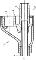
- Each rinsing arrangement comprises an outer tube 1 in which an inner tube 2 is arranged.
- An annular gap 3 is formed in sections between the outer tube 1 and the inner tube 2.
- the annular gap can also extend over the entire length of the outer tube 1 and the inner tube 2.
- an adapter piece 4 is arranged for connection to a drive and actuation unit (not shown), as is known from the prior art.
- An attachment 5 is provided at the end of the outer tube 1 facing away from the adapter piece 4.
- the adapter piece 4 covers one end of the outer tube 1 in a liquid-tight manner with its end facing the attachment 5.
- the design of the adapter piece 4 widens in the direction of the side facing away from the attachment 5.
- An insert 6 is arranged in the adapter piece, which has a pump holder 7 and a pipe section 8.
- the end of the inner tube 2 facing away from the adapter piece 4 is accommodated on one side of the pipe section 8.
- the other side of the pipe section 8 is intended for connecting another hose.
- a stable pump protrudes into the pump holder 7, which is sealed against the pump holder 7 by means of an O-ring and which supplies the flushing liquid; a suction hose is connected to the pipe section 8 to use the flushing arrangement, which drains the contaminated flushing liquid.
- This arrangement means that the flushing liquid is supplied to the attachment 5 through the annular gap 3 and the contaminated flushing liquid is drained through the inner pipe 2.
- the attachment 5 is designed differently, as can be seen from the figures.
- the attachment 5 is essentially bell-shaped.
- the attachment 5 In its area facing away from the adapter piece 4, the attachment 5 has a constriction 9, which is followed by a funnel-shaped section 10, which forms the free end of the attachment 5.
- outlet openings 11 for the rinsing liquid are formed in the attachment 5, adjacent to one another.
- the outlet openings 11 form the end of channels 12 which are formed in the attachment 5 and which are connected to the annular gap 3 at their ends facing away from the outlet openings 11.
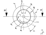
- the outlet openings 11 are clearly designed in such a way that the flushing liquid exits at an angle ⁇ and thus obliquely to the longitudinal center line of the flushing arrangement or the outer tube 1 and the inner tube 2 (cf. Figures 5 and 6 ).
- oblique means that the angle ⁇ deviates from the longitudinal center line of the flushing arrangement or the line running at right angles thereto at an acute or obtuse angle.
- the angle ⁇ is preferably between 5° and 85° to the longitudinal center line of the flushing arrangement.
- the rinsing liquid exits the outlet openings 11 in such a way that they are directed at the angle ⁇ towards the center of the rinsing arrangement, as indicated by the arrows.
- the rinsing liquid therefore hits the area to be rinsed at an angle in the center of the wound.
- the rinsing liquid also exits the outlet openings 11 at an angle ⁇ .
- the rinsing liquid also exits the attachment 5 at an angle ⁇ to the radial line due to a corresponding design of the outlet openings 11, as shown by the arrows in the left half of Figure 7 This causes the rinsing liquid to rotate, which creates a kind of turbulence, which further improves the rinsing result.
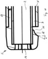
- the attachment 5 is designed like a cap.
- the attachment 5 is clearly rounded on the outside. It is provided with webs 13, the wall thickness of which corresponds to the height of the annular gap 3. When assembled, the webs 13 are accommodated in the annular gap 3. In its center, the attachment 5 is penetrated by an opening 14, which is aligned coaxially to the inner tube 2 and whose diameter essentially corresponds to the inner diameter of the inner tube 2. The contaminated rinsing liquid is thus sucked through the opening 14 to the inner tube 2 and discharged through it.
- Outlet openings 11 for the rinsing liquid are formed in the attachment 5.
- the outlet openings 11 are provided with an impact surface 15 which is designed in the manner of an outward-facing circular section.
- the circular section extends over an area of approximately 25°. It can be seen that the outermost end of the circular section of the impact surface 15 is neither parallel nor perpendicular to the longitudinal center line of the rinsing arrangement or the outer tube 1 and the inner tube 2. Consequently, the rinsing liquid emerges at an angle, namely at an angle ⁇ (see Figure 11).
- a type of comb can be provided at the opening 14, which can fulfill a filtering function. This can prevent the opening 14 or the inner tube 2 from becoming blocked.
- the attachment 5 is essentially hollow-cylindrical. It is pushed onto the end of the outer tube 1 with its end facing the adapter piece 4 and surrounds the area of the inner tube 2 that protrudes beyond the outer tube 1. At its end facing away from the adapter piece 4, the attachment 5 rests on the inner tube 2. In this area, the attachment 5 is also penetrated by an opening 14. The diameter of the opening 14 essentially corresponds to the inner diameter of the inner tube 2. Consequently, in this embodiment, the contaminated rinsing liquid is sucked through the opening 14 to the inner tube 2 and drained through it.
- the inner diameter of the attachment 5 corresponds essentially to the inner diameter of the outer tube 1. Consequently, an annular gap 16 is formed between the inner tube 2 and the attachment 5, which forms a continuation of the annular gap 3.
- the attachment 5 is provided with outlet openings 11, which are designed in the manner of windows. In the exemplary embodiment, four outlet openings 11 are formed, which are all around of the attachment 5. A different number of outlet openings 11 is possible.
- the outlet openings 11 can also be arranged at other locations on the attachment 5. It is also possible to provide several rings of outlet openings 11. In the outlet openings 11, impact surfaces 15 are provided which are neither parallel nor aligned at a right angle to the longitudinal center line of the flushing arrangement or of the outer tube 1 and the inner tube 2.
- the flushing liquid exits the attachment 5 at an angle, namely at an angle ⁇ .
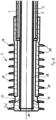
- the attachment 5 has bristles 18 on its circumference.
- the bristles 18 are made of the same material as the attachment. They are molded onto the attachment 5.
- the bristles 18 are arranged in rows in the manner of a helix on the circumference, as in particular Figure 18 can be seen.
- a helix, or also called a screw, helical line, cylindrical spiral or helix, is a curve that winds around the surface of a cylinder at a constant gradient.
- the rows of bristles thus follow a kind of spiral around the attachment 5. They each have two sharp edges 19 and a curve 20.
- the bristles are conical.
- the arrangement of the bristles on the circumference and the arrangement of the outlet openings between the bristles allow the rinsing liquid to escape between the bristles. Rinsing therefore takes place where the mechanical processing of the surface is also taking place at the same time.
- the rinsing arrangement according to the invention means that only one axial movement is required to reach all parts of the surface to be cleaned. Since the bristles are arranged in a helix-like manner on the circumference, they are positioned offset from one another. Their arrangement follows a spiral around the tube. This arrangement eliminates the problem of additional rotational movement. Only one axial insertion of the rinsing arrangement is required.
Landscapes
- Health & Medical Sciences (AREA)
- Heart & Thoracic Surgery (AREA)
- Life Sciences & Earth Sciences (AREA)
- General Health & Medical Sciences (AREA)
- Veterinary Medicine (AREA)
- Hematology (AREA)
- Anesthesiology (AREA)
- Animal Behavior & Ethology (AREA)
- Engineering & Computer Science (AREA)
- Public Health (AREA)
- Biomedical Technology (AREA)
- Pulmonology (AREA)
- Vascular Medicine (AREA)
- Surgery (AREA)
- Biophysics (AREA)
- Oral & Maxillofacial Surgery (AREA)
- Cleaning In General (AREA)
- Infusion, Injection, And Reservoir Apparatuses (AREA)
Claims (15)
- Agencement de rinçage pour systèmes de rinçage destinés à nettoyer les plaies chirurgicales au moyen d'un liquide de rinçage, comprenant un tube extérieur (1) dans lequel est disposé un tube intérieur (2), sachant qu'entre le tube extérieur (1) et le tube intérieur (2) est configuré au moins de façon segmentée un interstice annulaire (3), et qu'à l'extrémité libre du tube extérieur (1) est prévu un embout (5), qui présente des crins (18) sur sa périphérie, caractérisé en ce que les crins (18) sont disposés de façon hélicoïdale sur la périphérie de l'embout (5).
- Agencement de rinçage selon la revendication 1, caractérisé en ce que les crins (18) présentent respectivement deux arêtes vives et un arrondi.
- Agencement de rinçage selon l'une des revendications précédentes, caractérisé en ce que les crins (18) sont réalisés coniques.
- Agencement de rinçage selon la revendication 4, caractérisé en ce que dans l'embout (5) sont configurés des orifices de sortie (11) pour le liquide de rinçage, orifices dont la forme est telle que le liquide de rinçage sort selon un angle α et ainsi de biais par rapport à la ligne médiane longitudinale des tubes (1, 2).
- Agencement de rinçage selon la revendication 4, caractérisé en ce que l'angle α est compris entre 5° et 85° par rapport à la ligne longitudinale médiane.
- Agencement de rinçage selon la revendication 4 ou 5, caractérisé en ce que l'embout (5) entoure le tube intérieur (2) de façon segmentée.
- Agencement de rinçage selon l'une des revendications précédentes, caractérisé en ce que l'embout (5) est configuré en forme de capuchon.
- Agencement de rinçage selon la revendication 7, caractérisé en ce que l'embout (5) est réalisé arrondi à l'extérieur.
- Agencement de rinçage selon l'une des revendications précédentes, caractérisé en ce que l'embout (5) est traversé en son centre par un orifice (14) en coaxialité avec le tube intérieur (2).
- Agencement de rinçage selon la revendication 4, caractérisé en ce que les orifices de sortie (11) sont munis d'une chicane (15).
- Agencement de rinçage selon la revendication 10, caractérisé en ce que la chicane (15) est réalisée à la façon d'un segment circulaire orienté vers l'extérieur.
- Agencement de rinçage selon l'une des revendications précédentes, caractérisé en ce que l'embout (5) est configuré pour l'essentiel en forme cylindrique creuse.
- Agencement de rinçage selon l'une des revendications précédentes, caractérisé en ce que le diamètre intérieur de l'embout (5) correspond pour l'essentiel au diamètre intérieur du tube extérieur (1).
- Agencement de rinçage selon l'une des revendications précédentes, caractérisé en ce qu'entre le tube intérieur (2) et l'embout (5) est configuré un interstice annulaire (16).
- Agencement de rinçage selon l'une des revendications précédentes, caractérisé en ce que les orifices de sortie sont configurés de sorte que le liquide de rinçage sort, selon un angle β par rapport à la ligne radiale, par les orifices de sortie ménagés dans l'embout (5).
Applications Claiming Priority (1)
| Application Number | Priority Date | Filing Date | Title |
|---|---|---|---|
| DE202021100846.6U DE202021100846U1 (de) | 2021-02-19 | 2021-02-19 | Spülanordnung |
Publications (3)
| Publication Number | Publication Date |
|---|---|
| EP4046671A1 EP4046671A1 (fr) | 2022-08-24 |
| EP4046671B1 true EP4046671B1 (fr) | 2024-09-25 |
| EP4046671C0 EP4046671C0 (fr) | 2024-09-25 |
Family
ID=75683774
Family Applications (1)
| Application Number | Title | Priority Date | Filing Date |
|---|---|---|---|
| EP22157246.4A Active EP4046671B1 (fr) | 2021-02-19 | 2022-02-17 | Agencement de rinçage |
Country Status (2)
| Country | Link |
|---|---|
| EP (1) | EP4046671B1 (fr) |
| DE (1) | DE202021100846U1 (fr) |
Families Citing this family (2)
| Publication number | Priority date | Publication date | Assignee | Title |
|---|---|---|---|---|
| DE102022211360A1 (de) * | 2022-10-26 | 2024-05-02 | Raumedic Ag | Medizinischer Fluid-Konnektor |
| CN119235229B (zh) * | 2024-12-04 | 2025-03-21 | 湖南省华芯医疗器械有限公司 | 一种回弹结构、内窥镜及置入系统 |
Family Cites Families (5)
| Publication number | Priority date | Publication date | Assignee | Title |
|---|---|---|---|---|
| US20040215222A1 (en) * | 2003-04-25 | 2004-10-28 | Michael Krivoruchko | Intravascular material removal device |
| US20080146991A1 (en) * | 2006-12-18 | 2008-06-19 | Chris Hernandez | Hand operated dispenser for surgical irrigation fluids |
| DE202010011728U1 (de) | 2010-08-24 | 2010-11-04 | Interatio-Meditec Medizintechnik Vertriebs-Gmbh | Spülrohr für ein Spülsystem zur Reinigung von Operationswunden |
| DE102012000392A1 (de) | 2011-12-05 | 2013-06-06 | Heraeus Medical Gmbh | Adapter für Bohrantrieb und Lavage-System |
| CN111134953A (zh) * | 2020-01-13 | 2020-05-12 | 新乡医学院第一附属医院 | 一种耳内清洗上药装置 |
-
2021
- 2021-02-19 DE DE202021100846.6U patent/DE202021100846U1/de active Active
-
2022
- 2022-02-17 EP EP22157246.4A patent/EP4046671B1/fr active Active
Also Published As
| Publication number | Publication date |
|---|---|
| EP4046671A1 (fr) | 2022-08-24 |
| DE202021100846U1 (de) | 2021-04-09 |
| EP4046671C0 (fr) | 2024-09-25 |
Similar Documents
| Publication | Publication Date | Title |
|---|---|---|
| EP0402885B1 (fr) | Canal de sonde flexible | |
| DE69220056T2 (de) | Ophthalmische vorrichtung | |
| EP3041526B1 (fr) | Pièce à main destinée à nettoyer des blessures | |
| EP1250106A1 (fr) | Canule de rin age pour rincer le canal radiculaire d'une dent | |
| EP4046671A1 (fr) | Agencement de rinçage | |
| EP2251142B1 (fr) | Buse à usage unique | |
| EP2105106B1 (fr) | Dispositif de nettoyage médical destiné à nettoyer des surfaces internes | |
| DE102013108295B4 (de) | Reinigungsvorrichtung | |
| EP4278947A1 (fr) | Tige de rinçage réutilisable pour endoscope | |
| DE102005048211B4 (de) | Chirurgische Lagerung, chirurgisches System und Verfahren zum Reinigen | |
| DE3216564A1 (de) | Pneumatischer zahnsteinentferner | |
| EP2377562A2 (fr) | Système de rinçage pour le nettoyage de plaies opératoires | |
| EP1834600B1 (fr) | Dispositif destiné au nettoyage d'un arbre creux flexible d'un instrument médical | |
| DE102013214944A1 (de) | Sonotrode | |
| EP4046670B1 (fr) | Agencement de rinçage | |
| DE202004014828U1 (de) | Endoskopisches Instrument | |
| WO2019238918A1 (fr) | Résectoscope comprenant un tube de rinçage monté de manière à pouvoir coulisser longitudinalement | |
| EP1099804A1 (fr) | Toilette à vide | |
| EP1795217B1 (fr) | Canule d'aspiration | |
| DE102008023458B3 (de) | Handstückreinigungsadapter | |
| DE19535349C2 (de) | Doppelstromkanüle | |
| DE2640402C3 (de) | Choledochoskop oder Pyeloskop mit Spülwasserröhrchen | |
| DE3231693C2 (fr) | ||
| DE102022118531B4 (de) | Sondensystem für die endoluminale Unterdrucktherapie | |
| DE102022116383B4 (de) | Chirurgisches instrument, verfahren zu dessen montage und verfahren zu dessen demontage |
Legal Events
| Date | Code | Title | Description |
|---|---|---|---|
| PUAI | Public reference made under article 153(3) epc to a published international application that has entered the european phase |
Free format text: ORIGINAL CODE: 0009012 |
|
| STAA | Information on the status of an ep patent application or granted ep patent |
Free format text: STATUS: THE APPLICATION HAS BEEN PUBLISHED |
|
| AK | Designated contracting states |
Kind code of ref document: A1 Designated state(s): AL AT BE BG CH CY CZ DE DK EE ES FI FR GB GR HR HU IE IS IT LI LT LU LV MC MK MT NL NO PL PT RO RS SE SI SK SM TR |
|
| STAA | Information on the status of an ep patent application or granted ep patent |
Free format text: STATUS: REQUEST FOR EXAMINATION WAS MADE |
|
| 17P | Request for examination filed |
Effective date: 20230221 |
|
| RBV | Designated contracting states (corrected) |
Designated state(s): AL AT BE BG CH CY CZ DE DK EE ES FI FR GB GR HR HU IE IS IT LI LT LU LV MC MK MT NL NO PL PT RO RS SE SI SK SM TR |
|
| GRAP | Despatch of communication of intention to grant a patent |
Free format text: ORIGINAL CODE: EPIDOSNIGR1 |
|
| STAA | Information on the status of an ep patent application or granted ep patent |
Free format text: STATUS: GRANT OF PATENT IS INTENDED |
|
| INTG | Intention to grant announced |
Effective date: 20240503 |
|
| GRAS | Grant fee paid |
Free format text: ORIGINAL CODE: EPIDOSNIGR3 |
|
| GRAA | (expected) grant |
Free format text: ORIGINAL CODE: 0009210 |
|
| STAA | Information on the status of an ep patent application or granted ep patent |
Free format text: STATUS: THE PATENT HAS BEEN GRANTED |
|
| AK | Designated contracting states |
Kind code of ref document: B1 Designated state(s): AL AT BE BG CH CY CZ DE DK EE ES FI FR GB GR HR HU IE IS IT LI LT LU LV MC MK MT NL NO PL PT RO RS SE SI SK SM TR |
|
| REG | Reference to a national code |
Ref country code: GB Ref legal event code: FG4D Free format text: NOT ENGLISH |
|
| REG | Reference to a national code |
Ref country code: CH Ref legal event code: EP |
|
| REG | Reference to a national code |
Ref country code: DE Ref legal event code: R096 Ref document number: 502022001718 Country of ref document: DE |
|
| REG | Reference to a national code |
Ref country code: IE Ref legal event code: FG4D Free format text: LANGUAGE OF EP DOCUMENT: GERMAN |
|
| U01 | Request for unitary effect filed |
Effective date: 20241024 |
|
| U07 | Unitary effect registered |
Designated state(s): AT BE BG DE DK EE FI FR IT LT LU LV MT NL PT RO SE SI Effective date: 20241105 |
|
| PG25 | Lapsed in a contracting state [announced via postgrant information from national office to epo] |
Ref country code: NO Free format text: LAPSE BECAUSE OF FAILURE TO SUBMIT A TRANSLATION OF THE DESCRIPTION OR TO PAY THE FEE WITHIN THE PRESCRIBED TIME-LIMIT Effective date: 20241225 |
|
| PG25 | Lapsed in a contracting state [announced via postgrant information from national office to epo] |
Ref country code: GR Free format text: LAPSE BECAUSE OF FAILURE TO SUBMIT A TRANSLATION OF THE DESCRIPTION OR TO PAY THE FEE WITHIN THE PRESCRIBED TIME-LIMIT Effective date: 20241226 |
|
| PG25 | Lapsed in a contracting state [announced via postgrant information from national office to epo] |
Ref country code: RS Free format text: LAPSE BECAUSE OF FAILURE TO SUBMIT A TRANSLATION OF THE DESCRIPTION OR TO PAY THE FEE WITHIN THE PRESCRIBED TIME-LIMIT Effective date: 20241225 |
|
| PG25 | Lapsed in a contracting state [announced via postgrant information from national office to epo] |
Ref country code: RS Free format text: LAPSE BECAUSE OF FAILURE TO SUBMIT A TRANSLATION OF THE DESCRIPTION OR TO PAY THE FEE WITHIN THE PRESCRIBED TIME-LIMIT Effective date: 20241225 Ref country code: NO Free format text: LAPSE BECAUSE OF FAILURE TO SUBMIT A TRANSLATION OF THE DESCRIPTION OR TO PAY THE FEE WITHIN THE PRESCRIBED TIME-LIMIT Effective date: 20241225 Ref country code: GR Free format text: LAPSE BECAUSE OF FAILURE TO SUBMIT A TRANSLATION OF THE DESCRIPTION OR TO PAY THE FEE WITHIN THE PRESCRIBED TIME-LIMIT Effective date: 20241226 |
|
| U20 | Renewal fee for the european patent with unitary effect paid |
Year of fee payment: 4 Effective date: 20250204 |
|
| PG25 | Lapsed in a contracting state [announced via postgrant information from national office to epo] |
Ref country code: IS Free format text: LAPSE BECAUSE OF FAILURE TO SUBMIT A TRANSLATION OF THE DESCRIPTION OR TO PAY THE FEE WITHIN THE PRESCRIBED TIME-LIMIT Effective date: 20250125 |
|
| PG25 | Lapsed in a contracting state [announced via postgrant information from national office to epo] |
Ref country code: SM Free format text: LAPSE BECAUSE OF FAILURE TO SUBMIT A TRANSLATION OF THE DESCRIPTION OR TO PAY THE FEE WITHIN THE PRESCRIBED TIME-LIMIT Effective date: 20240925 |
|
| PG25 | Lapsed in a contracting state [announced via postgrant information from national office to epo] |
Ref country code: ES Free format text: LAPSE BECAUSE OF FAILURE TO SUBMIT A TRANSLATION OF THE DESCRIPTION OR TO PAY THE FEE WITHIN THE PRESCRIBED TIME-LIMIT Effective date: 20240925 |
|
| PG25 | Lapsed in a contracting state [announced via postgrant information from national office to epo] |
Ref country code: CZ Free format text: LAPSE BECAUSE OF FAILURE TO SUBMIT A TRANSLATION OF THE DESCRIPTION OR TO PAY THE FEE WITHIN THE PRESCRIBED TIME-LIMIT Effective date: 20240925 Ref country code: PL Free format text: LAPSE BECAUSE OF FAILURE TO SUBMIT A TRANSLATION OF THE DESCRIPTION OR TO PAY THE FEE WITHIN THE PRESCRIBED TIME-LIMIT Effective date: 20240925 |
|
| PG25 | Lapsed in a contracting state [announced via postgrant information from national office to epo] |
Ref country code: SK Free format text: LAPSE BECAUSE OF FAILURE TO SUBMIT A TRANSLATION OF THE DESCRIPTION OR TO PAY THE FEE WITHIN THE PRESCRIBED TIME-LIMIT Effective date: 20240925 |
|
| PLBE | No opposition filed within time limit |
Free format text: ORIGINAL CODE: 0009261 |
|
| STAA | Information on the status of an ep patent application or granted ep patent |
Free format text: STATUS: NO OPPOSITION FILED WITHIN TIME LIMIT |
|
| 26N | No opposition filed |
Effective date: 20250626 |
|
| PG25 | Lapsed in a contracting state [announced via postgrant information from national office to epo] |
Ref country code: MC Free format text: LAPSE BECAUSE OF FAILURE TO SUBMIT A TRANSLATION OF THE DESCRIPTION OR TO PAY THE FEE WITHIN THE PRESCRIBED TIME-LIMIT Effective date: 20240925 |
|
| REG | Reference to a national code |
Ref country code: CH Ref legal event code: PL |
|
| PG25 | Lapsed in a contracting state [announced via postgrant information from national office to epo] |
Ref country code: CH Free format text: LAPSE BECAUSE OF NON-PAYMENT OF DUE FEES Effective date: 20250228 |
|
| PG25 | Lapsed in a contracting state [announced via postgrant information from national office to epo] |
Ref country code: HR Free format text: LAPSE BECAUSE OF FAILURE TO SUBMIT A TRANSLATION OF THE DESCRIPTION OR TO PAY THE FEE WITHIN THE PRESCRIBED TIME-LIMIT Effective date: 20240925 |
|
| PG25 | Lapsed in a contracting state [announced via postgrant information from national office to epo] |
Ref country code: IE Free format text: LAPSE BECAUSE OF NON-PAYMENT OF DUE FEES Effective date: 20250217 |
|
| U20 | Renewal fee for the european patent with unitary effect paid |
Year of fee payment: 5 Effective date: 20260203 |