EP4046692A1 - Brandbekämpfungsvorrichtung und brandbekämpfungssystem - Google Patents
Brandbekämpfungsvorrichtung und brandbekämpfungssystem Download PDFInfo
- Publication number
- EP4046692A1 EP4046692A1 EP20924971.3A EP20924971A EP4046692A1 EP 4046692 A1 EP4046692 A1 EP 4046692A1 EP 20924971 A EP20924971 A EP 20924971A EP 4046692 A1 EP4046692 A1 EP 4046692A1
- Authority
- EP
- European Patent Office
- Prior art keywords
- fire
- switch
- fire detection
- relay
- detection switches
- Prior art date
- Legal status (The legal status is an assumption and is not a legal conclusion. Google has not performed a legal analysis and makes no representation as to the accuracy of the status listed.)
- Granted
Links
Images

Classifications
-
- G—PHYSICS
- G08—SIGNALLING
- G08B—SIGNALLING SYSTEMS, e.g. PERSONAL CALLING SYSTEMS; ORDER TELEGRAPHS; ALARM SYSTEMS
- G08B29/00—Checking or monitoring of signalling or alarm systems; Prevention or correction of operating errors, e.g. preventing unauthorised operation
- G08B29/18—Prevention or correction of operating errors
- G08B29/185—Signal analysis techniques for reducing or preventing false alarms or for enhancing the reliability of the system
- G08B29/188—Data fusion; cooperative systems, e.g. voting among different detectors
-
- A—HUMAN NECESSITIES
- A62—LIFE-SAVING; FIRE-FIGHTING
- A62C—FIRE-FIGHTING
- A62C37/00—Control of fire-fighting equipment
- A62C37/04—Control of fire-fighting equipment with electrically-controlled release
-
- G—PHYSICS
- G08—SIGNALLING
- G08B—SIGNALLING SYSTEMS, e.g. PERSONAL CALLING SYSTEMS; ORDER TELEGRAPHS; ALARM SYSTEMS
- G08B17/00—Fire alarms; Alarms responsive to explosion
- G08B17/06—Electric actuation of the alarm, e.g. using a thermally-operated switch
-
- G—PHYSICS
- G08—SIGNALLING
- G08B—SIGNALLING SYSTEMS, e.g. PERSONAL CALLING SYSTEMS; ORDER TELEGRAPHS; ALARM SYSTEMS
- G08B17/00—Fire alarms; Alarms responsive to explosion
- G08B17/10—Actuation by presence of smoke or gases, e.g. automatic alarm devices for analysing flowing fluid materials by the use of optical means
-
- H—ELECTRICITY
- H02—GENERATION; CONVERSION OR DISTRIBUTION OF ELECTRIC POWER
- H02J—ELECTRIC POWER NETWORKS; CIRCUIT ARRANGEMENTS OR SYSTEMS FOR SUPPLYING OR DISTRIBUTING ELECTRIC POWER; SYSTEMS FOR STORING ELECTRIC ENERGY
- H02J7/00—Circuit arrangements for charging or discharging batteries or for supplying loads from batteries
- H02J7/855—Circuit arrangements for charging or discharging batteries or for supplying loads from batteries with circuits adapted for supplying loads from the battery
-
- A—HUMAN NECESSITIES
- A62—LIFE-SAVING; FIRE-FIGHTING
- A62C—FIRE-FIGHTING
- A62C37/00—Control of fire-fighting equipment
- A62C37/36—Control of fire-fighting equipment an actuating signal being generated by a sensor separate from an outlet device
- A62C37/38—Control of fire-fighting equipment an actuating signal being generated by a sensor separate from an outlet device by both sensor and actuator, e.g. valve, being in the danger zone
- A62C37/40—Control of fire-fighting equipment an actuating signal being generated by a sensor separate from an outlet device by both sensor and actuator, e.g. valve, being in the danger zone with electric connection between sensor and actuator
-
- G—PHYSICS
- G08—SIGNALLING
- G08B—SIGNALLING SYSTEMS, e.g. PERSONAL CALLING SYSTEMS; ORDER TELEGRAPHS; ALARM SYSTEMS
- G08B25/00—Alarm systems in which the location of the alarm condition is signalled to a central station, e.g. fire or police telegraphic systems
- G08B25/01—Alarm systems in which the location of the alarm condition is signalled to a central station, e.g. fire or police telegraphic systems characterised by the transmission medium
- G08B25/04—Alarm systems in which the location of the alarm condition is signalled to a central station, e.g. fire or police telegraphic systems characterised by the transmission medium using a single signalling line, e.g. in a closed loop
Definitions
- This application relates to the field of battery technologies, and in particular, to a fire-fighting switch device and a fire-fighting system.
- a fire controller makes judgments by collecting signals from a smoke detector and a heat detector. When a smoke alarm and a heat alarm simultaneously occur, the fire controller works with a fire-extinguishing apparatus to extinguish a fire.
- a fire controller needs to use a code addressing scheme to obtain location of the detector, which makes the fire-fighting system highly complex.
- Embodiments of this application are intended to provide a fire-fighting switch device and a fire-fighting system to resolve the technical problem of high complexity of fire-fighting systems.
- an embodiment of this application provides a fire-fighting switch device, including: a plurality of fire detection switch units, where the fire detection switch unit includes one or more fire detection switches, the one or more fire detection switches form at least one switch path, and the fire detection switch is configured to turn on when a fire is detected, where any one of the switch paths is configured to transmit a voltage signal to a fire-extinguishing device when all of the fire detection switches on the switch path are turned on.
- the fire-extinguishing device can be controlled to extinguish the fire provided that all fire detection switches on one switch path in the fire detection switch unit are turned on. Therefore, code addressing is unnecessary for determining where an anomaly has occurred, thereby reducing computation and making the fire-fighting switch device work with less complexity.
- the fire detection switch includes a first relay and a sensor assembly, and the sensor assembly is configured to control the first relay to turn on when a fire is detected, so as to turn on the fire detection switch.
- the sensor assembly and the first relay cooperate to implement an addressing function, which not only makes the fire-fighting switch device work with less complexity, but also reduces costs of the fire-fighting switch device.
- the use of relay control is more reliable and time-efficient than the way of logic judgments by a host.
- the first relays of the plurality of fire detection switches are connected in series to form one switch path, and the sensor assemblies of the plurality of fire detection switches that are sequentially connected are sensor assemblies of different types.
- corresponding first relays can be turned on, that is, a corresponding switch path can be turned on, only when a plurality of sensor assemblies of different types all detect a fire. Therefore, possibility of the fire-extinguishing device being touched by mistake can be reduced.
- the plurality of fire detection switches form a plurality of switch paths
- the sensor assemblies of the plurality of fire detection switches are sensor assemblies of a same type
- the first relays of the plurality of fire detection switches are connected in parallel to form the plurality of switch paths.
- the plurality of fire detection switches form a plurality of switch paths; the plurality of fire detection switches include at least two types of fire detection switches, and different types of fire detection switches are provided with different types of sensor assemblies; and first relays of fire detection switches of a same type in the plurality of fire detection switches are connected in parallel and first relays of fire detection switches of different types in the plurality of fire detection switches are connected in series, to form the plurality of switch paths.
- first relays of fire detection switches of a same type in the plurality of fire detection switches are connected in parallel and first relays of fire detection switches of different types in the plurality of fire detection switches are connected in series, to form the plurality of switch paths.
- the sensor assembly is a smoke sensor, a temperature sensor, or an infrared sensor.
- various types of sensor assemblies can be selected depending on actual conditions of the electrical device, so as to ensure fire distinguishing accuracy of the fire-fighting switch device.
- the fire-fighting switch device further includes: a power supply interface assembly, and the power supply interface assembly includes: a first interface configured to provide the voltage signal to the first relays of the fire detection switches; and a second interface configured to supply power to the sensor assemblies of the fire detection switches.
- an embodiment of this application provides a fire-fighting system, including the fire-fighting switch device according to the first aspect and a battery management unit, where the fire detection switch further includes a second relay connected to the battery management unit; a sensor assembly is further configured to control the second relay to turn on when a fire is detected; and the battery management unit is further connected to a battery in an electrical device and configured to control the battery in the electrical device to stop supplying power when the second relay is detected to have been turned on.
- the battery management unit can control the battery to stop supplying power when the second relay is turned on.
- the fire-fighting system further includes the fire-extinguishing device, where the fire-extinguishing device includes a fire-extinguishing assembly and a third relay, and the third relay is connected to the battery management unit; and the battery management unit is further configured to control the battery in the electrical device to stop supplying power when the third relay is detected to have been turned on.
- the battery management unit can control the battery to stop supplying power when the third relay is turned on.
- the battery management unit is further configured to give an alarm when the second relay is turned on or when the third relay is turned on.
- the battery management unit can give an alarm to remind management personnel that the electrical device is having a fire.
- the fire-extinguishing device includes an aerosol generator.
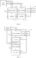
- FIG. 1 is a schematic structural diagram of a fire-fighting switch device according to an embodiment of this application.
- the fire-fighting switch device 10 may include a plurality of fire detection switch units 100, where the fire detection switch unit 100 includes one or more fire detection switches 110, the one or more fire detection switches 110 form at least one switch path, the fire detection switch 110 is configured to turn on when a fire is detected, and any one of the switch paths is configured to transmit a voltage signal to a fire-extinguishing device 30 when all of the fire detection switches 110 on the switch path are turned on.
- FIG. 1 Only three fire detection switch units 100 are shown in FIG. 1 . It can be understood that the number of the fire detection switch units 100 in the fire-fighting switch device 10 is not limited to three, and those skilled in the art can make adjustments based on actual situations.
- an electrical device that requires fire monitoring is used as an example, and the electrical device may be a device that needs electricity such as a battery cabinet, a voltage box, or the like.
- An electrical layout generally includes a plurality of electrical devices, which means that fire monitoring is required for all the plurality of electrical devices.
- each of the electrical devices is provided with one fire detection switch unit 100.
- One end of fire detection switch unit 100 is connected to a power supply, and the other end is connected to the fire-extinguishing device 30. When one switch path in the fire detection switch unit 100 is turned on, the fire-extinguishing device 30 starts to work.
- the fire detection switch units 100 being connected in parallel allow separate control on each electrical device, and a fire-fighting action in one electrical device does not affect normal operation of other electrical devices and the fire detection switch units 100 in the electrical devices.
- the fire detection switch units 100 may be provided either entirely or partially in the electrical device.
- the fire detection switch unit 100 includes a relay and a sensor assembly 112
- the sensor assembly 112 can be provided in the electrical device, and the relay can be provided outside the electrical device. This is not particularly limited in the embodiments of this application.
- the fire-fighting switch device according to this embodiment of this application can be applied to any area where fire monitoring is required.
- the fire-fighting switch device can be applied to warehouses where inflammables are stored and high-temperature work plants. This is not particularly limited in the embodiments of this application.
- Each of the fire detection switch units 100 may include one or more fire detection switches 110.
- the fire detection switch 110 may include a relay (named as a first relay 111 for ease of description) and a sensor assembly 112.
- the first relay 111 may be disposed on a base of the sensor assembly 112 to jointly form one fire detection switch 110.
- the sensor assembly 112 can control the first relay 111 on the base to turn on. At this point, it can be considered that the corresponding fire detection switch 110 is turned on.
- various types of sensor assemblies 112 are available for choice, for example, smoke sensors, temperature sensors, or infrared sensors. This is not particularly limited in the embodiments of this application, and those skilled in the art can select an appropriate sensor assembly 112 based on an actual situation of the area where fire monitoring is required, so as to ensure fire-extinguishing accuracy of the fire-fighting switch device 10.
- the sensor assembly 112 including a smoke sensor and a temperature sensor is used as an example.
- the fire detection switch 110 can be implemented by selecting a 45681-256 series base with smoke and temperature sensors.
- the fire-fighting switch device 10 may further include a power supply interface assembly, where the power supply interface assembly includes: a first interface configured to provide the voltage signal to the first relay 111 of the fire detection switch 110; and a second interface configured to supply power to the sensor assembly of the fire detection switch 110.
- the relay in the fire detection switch 110 may use other elements providing a switching function, for example, a single-pole double-throw switch; and the sensor assembly 112 in the fire detection switch 110 may be a device with a communication function to receive fire information sent by an external device.
- a switching function for example, a single-pole double-throw switch
- the sensor assembly 112 in the fire detection switch 110 may be a device with a communication function to receive fire information sent by an external device.
- This is not particularly limited in the embodiments of this application, and those skilled in the art can make appropriate adjustments based on actual conditions in combination with conventional technical means in the field.
- one fire detection switch 110 may include a plurality of relays or a plurality of sensor assemblies 112.
- each of the fire detection switch units 100 includes only one fire detection switch 110, the fire detection switch 110 forms a separate switch path, and therefore the voltage signal is transmitted to the fire-extinguishing device 30 to extinguish the fire when the fire detection switch 110 is turned on.
- the fire detection switch 110 including a first relay 111 and a sensor assembly 112 is used as an example.
- FIG. 2 is a schematic structural diagram of another fire-fighting switch device according to an embodiment of this application.
- the sensor assembly 112 in the fire detection switch 110 is connected to a power supply, one end of the first relay 111 in the fire detection switch 110 is connected to the power supply, and the other end of the first relay 111 is connected to the fire-extinguishing device 30.
- the sensor assembly 112 detects a fire the first relay 111 is closed, and the fire-extinguishing device 30 starts to work.
- the first relay 111, the fire-extinguishing device 30, and the power supply form a switch path.
- FIG. 2 only shows an implementation of the fire-fighting switch device 10 in one electrical device.
- the fire-fighting switch device 10 in each electrical device can be implemented in the way shown in FIG. 2 .
- each of the fire detection switch units 100 includes a plurality of fire detection switches 110
- the plurality of fire detection switches 110 form at least one switch path.
- the fire detection switch 110 including a first relay 111 and a sensor assembly 112 is used as an example. There are various cases of connection relationships in each fire detection switch unit 100.
- the first relays 111 of the plurality of fire detection switches 110 are connected in series to form one switch path, and the sensor assemblies 112 of the plurality of fire detection switches 110 that are sequentially connected are sensor assemblies of different types.
- the first relays 111 of the plurality of fire detection switches 110 are connected in parallel to form a plurality of switch paths, and the sensor assemblies 112 of the plurality of fire detection switches 110 are sensor assemblies 112 of a same type.
- the plurality of fire detection switches 110 include at least two types of fire detection switches 110, and different types of fire detection switches 110 are provided with different types of sensor assemblies 112.
- First relays 111 of fire detection switches 110 of a same type in the plurality of fire detection switches 110 are connected in parallel and first relays 111 of fire detection switches 110 of different types in the plurality of fire detection switches 110 are connected in series, to form a plurality of switch paths.
- FIG. 3 is a schematic structural diagram of a fire-fighting switch device in the first case according to an embodiment of this application.
- the first relays 111 in the plurality of fire detection switches 110 are connected in series to form one switch path, and each of the first relays 111 corresponds to one sensor assembly 112.
- Each of the sensor assemblies 112 is of a different type, and therefore the formed switch path can be turned on and the fire-extinguishing device 30 can start to work only when all of the sensor assemblies 112 detect a fire.
- one fire detection switch unit 100 includes one smoke sensor, one temperature sensor, and first relays 111 corresponding to the two sensors.
- the power supply, two first relays 111, and the fire-extinguishing device 30 form one switch path. If only the smoke sensor detects heavy smoke in an area that requires fire monitoring or only the temperature sensor detects an abnormal temperature rise in the area that requires fire monitoring, the switch path will not turn on and the fire-extinguishing device 30 will not start to work because only one first relay 111 is turned on; and if the smoke sensor detects heavy smoke in the area that requires fire monitoring and the temperature sensor detects an abnormal temperature rise in the area that requires fire monitoring, the switch path is turned on and the fire-extinguishing device 30 starts to work because the two first relays 111 are both closed.
- FIG. 4 is a schematic structural diagram of a fire-fighting switch device in the second case according to an embodiment of this application.
- the first relays 111 of the plurality of fire detection switches 110 are connected in parallel to form a plurality of switch paths, and each of the first relays 111 corresponds to one sensor assembly 112.
- the power supply, one first relay 111, and the fire-extinguishing device 30 form one switch path.
- All of the sensor assemblies 112 are of the same type. Therefore, when one sensor assembly 112 in the plurality of sensor assemblies 112 detects a fire, a corresponding switch path is turned on, and the fire-extinguishing device 30 can start to work.
- one fire detection switch unit 100 includes two smoke sensors and first relays 111 corresponding to the two sensors. If one of the smoke sensors detects heavy smoke in an area that requires fire monitoring, a first relay 111 corresponding to that smoke sensor is turned on, and therefore a switch path corresponding to the first relay 111 is turned on, and the fire-extinguishing device 30 starts to work.
- a plurality of sensor assemblies 112 of a same type can be provided in different areas of the electrical device, so that the electrical device can be monitored in multiple areas. Therefore, in this embodiment of this application, employing the foregoing second case can reduce possibility of false negatives given by the sensor assemblies 112.
- the foregoing third case can be considered as a combination of the first case and the second case, where each of the fire detection switch units 100 includes a plurality of switch paths, and the first case is applied on each switch path, that is, first relays 111 of fire detection switches 110 of different types are connected in series; while the second case is applied across a plurality of switch paths, that is, first relays 111 of fire detection switches 110 of a same type in the plurality of fire detection switches 110 are connected in parallel.
- the third case are not further described in the embodiments of this application, and those skilled in the art can implement the third case according to the implementations of the first case and the second case. It can be understood that in the embodiments of this application, employing the third case can reduce both possibility of touching the fire-extinguishing device 30 by mistake and possibility of false negatives given by the sensor assemblies 112.
- the fire-extinguishing device 30 can be controlled to extinguish the fire provided that all fire detection switches 110 on one switch path in the electrical device are turned on, thereby reducing computation and making the fire-fighting switch device 10 work with less complexity.
- the sensor assembly 112 and the first relay 111 cooperate to implement an addressing function, which reduces costs of the fire-fighting switch device 10 while making the fire-fighting switch device 10 work with less complexity.
- the use of relay control is more reliable and time-efficient than the way of logic judgments by a host.
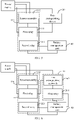
- FIG. 5 is a schematic structural diagram of a fire-fighting system according to an embodiment of this application.
- the fire-fighting system may include the fire-fighting switch device 10 in the foregoing embodiments and a battery management unit 40; the fire detection switch 110 further includes a second relay 113 connected to the battery management unit 40; the sensor assembly 112 is further configured to control the second relay 113 to turn on when detecting a fire; and the battery management unit 40 is further connected to a battery in an electrical device and configured to control the battery in the electrical device to stop supplying power when the second relay 113 is detected to have been turned on.
- FIG. 5 shows a case where only one fire detection switch unit 100 is included in the fire-fighting switch device 10.
- the fire detection switch 110 may further include a second relay 113.
- the second relay 113 similar to the first relay 111, may be disposed on the base of the sensor assembly 112, and the first relay 111, the second relay 113, and the sensor assembly 112 together form one fire detection switch 110.
- the sensor assembly 112 can control both the first relay 111 and the second relay 113 on the base to turn on.
- the second relay 113 may be connected to the battery management unit 40, and the battery management unit 40 may detect whether the second relay 113 is turned on or not.
- the battery management unit 40 may consider that the sensor assembly 112 corresponding to the second relay 113 has detected a fire.
- the battery management unit 40 may consider that the electrical device is having a fire. At this point, the battery management unit 40 may control the battery in the electrical device to stop supplying power and perform operations such as alarming.
- the battery management unit 40 considers that a fire has occurred in the electrical device when a corresponding second relay 113 is detected to have been turned on.
- each of the fire detection switch units 100 includes a plurality of fire detection switches 110 and the first case in the foregoing embodiments is employed.
- the battery management unit 40 considers that a fire has occurred in the electrical device when detecting that all of the second relays 113 corresponding to the first relays 111 that are connected in series are closed.
- the battery management unit 40 can control the battery to stop supplying power when the second relay 113 is turned on.
- FIG. 6 is a schematic structural diagram of another fire-fighting system according to an embodiment of this application.
- the fire-fighting system may further include a fire-extinguishing device 30, where the fire-extinguishing device 30 includes a fire-extinguishing assembly 302 and a third relay 301, the third relay 301 is connected to the battery management unit 40, and the battery management unit 40 is further configured to control a battery in an electrical device to stop supplying power when the third relay 301 is detected to have been turned on.
- FIG. 6 also shows a case where only one fire detection switch unit 100 is included in the fire-fighting switch device 10.
- the fire-extinguishing assembly 302 in the fire-extinguishing device 30 is connected to a power supply, and the fire-extinguishing device 30 may further include a relay (named as the third relay 301 for ease of description).
- the third relay 301 similar to the second relay 113, may be disposed on a base of the fire-extinguishing assembly 302, and the third relay 301 and the sensor assembly 112 together form the fire-extinguishing device 30.
- the third relay 301 on the base may be controlled to turn on.
- the fire-extinguishing device 30 may include an aerosol generator.
- the third relay 301 may be connected to the battery management unit 40, and the battery management unit 40 may detect whether the third relay 301 is turned on or not. When a third relay is turned on, the battery management unit 40 may consider that a fire-extinguishing assembly 302 corresponding to the third relay 301 starts to work, which means that a fire has occurred in the electrical device. In this case, the battery management unit 40 may control a battery in the electrical device to stop supplying power and perform operations such as alarming.
- the battery management unit 40 can give an alarm when the third relay 301 is turned on.
- the fire-fighting system can be applied to various battery energy storage systems.
- the fire-fighting switch device 10 may be configured in a control unit of a container battery system; and for a station-type energy storage system or an outdoor electric cabinet energy storage system, the fire-fighting switch device 10 may be configured in a main control cabinet of the energy storage system.
Landscapes
- Business, Economics & Management (AREA)
- Emergency Management (AREA)
- Physics & Mathematics (AREA)
- General Physics & Mathematics (AREA)
- Chemical & Material Sciences (AREA)
- Analytical Chemistry (AREA)
- Engineering & Computer Science (AREA)
- Power Engineering (AREA)
- Computer Security & Cryptography (AREA)
- Health & Medical Sciences (AREA)
- Public Health (AREA)
- Fire Alarms (AREA)
Priority Applications (1)
| Application Number | Priority Date | Filing Date | Title |
|---|---|---|---|
| HUE20924971A HUE067510T2 (hu) | 2020-12-25 | 2020-12-25 | Tûzoltó kapcsolóberendezés és tûzoltórendszer |
Applications Claiming Priority (1)
| Application Number | Priority Date | Filing Date | Title |
|---|---|---|---|
| PCT/CN2020/139606 WO2022134066A1 (zh) | 2020-12-25 | 2020-12-25 | 一种消防开关设备以及消防系统 |
Publications (3)
| Publication Number | Publication Date |
|---|---|
| EP4046692A1 true EP4046692A1 (de) | 2022-08-24 |
| EP4046692A4 EP4046692A4 (de) | 2023-01-18 |
| EP4046692B1 EP4046692B1 (de) | 2024-06-05 |
Family
ID=82117405
Family Applications (1)
| Application Number | Title | Priority Date | Filing Date |
|---|---|---|---|
| EP20924971.3A Active EP4046692B1 (de) | 2020-12-25 | 2020-12-25 | Brandbekämpfungsvorrichtung und brandbekämpfungssystem |
Country Status (6)
| Country | Link |
|---|---|
| US (1) | US11694530B2 (de) |
| EP (1) | EP4046692B1 (de) |
| CN (1) | CN116096465B (de) |
| HU (1) | HUE067510T2 (de) |
| PL (1) | PL4046692T3 (de) |
| WO (1) | WO2022134066A1 (de) |
Families Citing this family (1)
| Publication number | Priority date | Publication date | Assignee | Title |
|---|---|---|---|---|
| CN120748117B (zh) * | 2025-09-04 | 2025-11-14 | 珠海众特科技有限公司 | 一种具有警报结构的消防电气火灾监控装置 |
Family Cites Families (28)
| Publication number | Priority date | Publication date | Assignee | Title |
|---|---|---|---|---|
| US4027302A (en) * | 1976-06-03 | 1977-05-31 | W. E. Healey & Associates, Inc. | Double detection circuit for conserving energy in fire detection systems and the like |
| WO2007143100A2 (en) * | 2006-06-01 | 2007-12-13 | Whitney Projects, Llc | Fire suppression systems and methods |
| US8378834B1 (en) * | 2008-05-02 | 2013-02-19 | Captive-Aire Systems, Inc. | Kitchen hood assembly with fire suppression control system including multiple monitoring circuits |
| US7963282B2 (en) * | 2008-05-02 | 2011-06-21 | Captive-Aire Systems, Inc. | Kitchen hood assembly with a combination cleaning and fire suppression system |
| US20100078184A1 (en) * | 2008-09-29 | 2010-04-01 | Pellittiere Ii Michael M | Fixed residential fire suppression system |
| US8846232B2 (en) * | 2009-11-11 | 2014-09-30 | Atieva, Inc. | Flash cooling system for increased battery safety |
| DE102010028858A1 (de) * | 2010-05-11 | 2011-11-17 | Fiwarec Valves & Regulators Gmbh & Co. Kg | Ventil |
| EP2586496A1 (de) * | 2010-06-24 | 2013-05-01 | Hochiki Corporation | Brandverhütungsvorrichtung |
| US9956445B2 (en) * | 2010-12-30 | 2018-05-01 | William Armand Enk, SR. | Fire suppression system |
| US9550080B2 (en) * | 2011-06-17 | 2017-01-24 | United Parcel Service Of America, Inc. | Suppressing a fire condition in an aircraft |
| US9526931B2 (en) * | 2012-12-07 | 2016-12-27 | The Boeing Company | Cargo fire-suppression agent distribution system |
| ES2588103T3 (es) * | 2014-01-17 | 2016-10-28 | Minimax Gmbh & Co Kg | Procedimiento e instalación para la extinción con un agente extintor sintético líquido y agua |
| US10343003B2 (en) * | 2014-10-02 | 2019-07-09 | The Boeing Company | Aircraft fire suppression system and method |
| US9907985B2 (en) * | 2015-04-09 | 2018-03-06 | Umm Al-Qura University | Fire risk detection and suppression in a modular gas supply system |
| US9714718B2 (en) * | 2015-06-05 | 2017-07-25 | Tlx Technologies, Llc | Sensor for connection detection and actuator including same |
| US20170293478A1 (en) * | 2016-04-11 | 2017-10-12 | Tyco Fire & Security Gmbh | Fire detection system with automatic firmware updating |
| US10453320B2 (en) * | 2016-04-11 | 2019-10-22 | Johnson Controls Fire Protection LP | Addressing method for slave units in fire detection system |
| US10860541B2 (en) * | 2016-04-11 | 2020-12-08 | Johnson Controls Fire Protection LP | Fire detection system with distributed file system |
| CN206416815U (zh) * | 2016-11-28 | 2017-08-18 | 姜闻 | 自动感应逃生窗 |
| CN206809567U (zh) * | 2017-03-23 | 2017-12-29 | 株洲海畅铁路机车配件有限公司 | 机车灭火装置 |
| IT201700041390A1 (it) * | 2017-04-13 | 2018-10-13 | Lug Prince & Decker S R L | Sistema antincendio per veicoli |
| KR101881360B1 (ko) * | 2018-02-08 | 2018-07-25 | 김석원 | 안전한 대피를 위한 소방표시기구 |
| CN208208915U (zh) * | 2018-05-08 | 2018-12-07 | 郑州深澜动力科技有限公司 | 一种集成火情控制的电池及其管理装置 |
| CN208525702U (zh) * | 2018-05-30 | 2019-02-22 | 广州市普利达消防工程有限公司 | 一种室内消防自动喷水灭火系统 |
| CN110115815A (zh) * | 2019-04-10 | 2019-08-13 | 惠州亿纬锂能股份有限公司 | 新能源动力电池系统注液式消防系统 |
| CN110975204B (zh) * | 2019-11-09 | 2022-01-07 | 许继集团有限公司 | 一种储能舱及其控制系统 |
| CN211015817U (zh) * | 2019-11-22 | 2020-07-14 | 何排枝 | 一种智能消防联络开关系统 |
| CN212182484U (zh) * | 2020-04-17 | 2020-12-18 | 中航锂电技术研究院有限公司 | 热失控管理设备、电池组及电池包 |
-
2020
- 2020-12-25 EP EP20924971.3A patent/EP4046692B1/de active Active
- 2020-12-25 PL PL20924971.3T patent/PL4046692T3/pl unknown
- 2020-12-25 HU HUE20924971A patent/HUE067510T2/hu unknown
- 2020-12-25 CN CN202080104264.5A patent/CN116096465B/zh active Active
- 2020-12-25 WO PCT/CN2020/139606 patent/WO2022134066A1/zh not_active Ceased
-
2021
- 2021-10-20 US US17/505,965 patent/US11694530B2/en active Active
Also Published As
| Publication number | Publication date |
|---|---|
| CN116096465B (zh) | 2025-03-28 |
| WO2022134066A1 (zh) | 2022-06-30 |
| HUE067510T2 (hu) | 2024-10-28 |
| EP4046692B1 (de) | 2024-06-05 |
| PL4046692T3 (pl) | 2024-09-09 |
| US11694530B2 (en) | 2023-07-04 |
| US20220207976A1 (en) | 2022-06-30 |
| CN116096465A (zh) | 2023-05-09 |
| EP4046692A4 (de) | 2023-01-18 |
Similar Documents
| Publication | Publication Date | Title |
|---|---|---|
| KR101258018B1 (ko) | 고집적 데이터 버스 자동 소화 시스템 | |
| KR102197304B1 (ko) | IoT 기반의 소화 장치를 이용한 통합 소방방재 장치 및 방법 | |
| KR100816984B1 (ko) | 배전반 화재감시제어기 | |
| US6288637B1 (en) | Fire protection system | |
| US11694530B2 (en) | Fire-fighting switch device and fire-fighting system | |
| CN208092902U (zh) | 一种智能总线式烟火报警系统 | |
| KR20220007031A (ko) | 선로변기능모듈의 모니터링 장치 | |
| CN201917991U (zh) | 一种具有直接打印功能的电气火灾监控系统 | |
| CN110086250A (zh) | 智慧安全用电监控装置及其应用的智慧安全用电管理系统 | |
| CN113759291B (zh) | 故障检测方法、装置、储能系统及可读存储介质 | |
| KR20050064510A (ko) | 원격제어 소방시스템 | |
| CN219068259U (zh) | 一种具有联网功能的防火门监控主机 | |
| CN118370951A (zh) | 一种消防灭火液冷储能系统 | |
| NL2036557A (en) | The monitoring system for remote contactless diagnostics and control of automatic fire extinguishing devices for local protection of electrical devices | |
| TWI524621B (zh) | 電源管理系統及其控制方法 | |
| KR102182157B1 (ko) | 에너지 저장 장치를 보호하기 위한 이중화 보호 장치 및 이를 갖는 에너지 저장 시스템 | |
| KR102937776B1 (ko) | 통합전력제어장치를 구비한 산업용 조명설비 관리시스템 | |
| KR20220150665A (ko) | 화재발생감지 및 소화 기능이 구비된 지상개폐기 | |
| KR102393975B1 (ko) | 다단 랙 모니터링 시스템 | |
| JP7755566B2 (ja) | 防災監視システム | |
| KR102906309B1 (ko) | R형 수신기를 이용한 p형 수신기 제어 시스템 | |
| KR100862608B1 (ko) | 경고 메시지 전송장치 | |
| EP4597006A1 (de) | Verwaltungsvorrichtung für kältekreislaufvorrichtung | |
| Sărăcin et al. | Integration of residential alarm systems into electric power supplies of vital consumers | |
| TR2025020965A2 (tr) | Veri Merkezi Lityum İyon Akü Yedeklemesi ve Otomasyonu |
Legal Events
| Date | Code | Title | Description |
|---|---|---|---|
| STAA | Information on the status of an ep patent application or granted ep patent |
Free format text: STATUS: UNKNOWN |
|
| STAA | Information on the status of an ep patent application or granted ep patent |
Free format text: STATUS: THE INTERNATIONAL PUBLICATION HAS BEEN MADE |
|
| PUAI | Public reference made under article 153(3) epc to a published international application that has entered the european phase |
Free format text: ORIGINAL CODE: 0009012 |
|
| STAA | Information on the status of an ep patent application or granted ep patent |
Free format text: STATUS: REQUEST FOR EXAMINATION WAS MADE |
|
| 17P | Request for examination filed |
Effective date: 20210920 |
|
| AK | Designated contracting states |
Kind code of ref document: A1 Designated state(s): AL AT BE BG CH CY CZ DE DK EE ES FI FR GB GR HR HU IE IS IT LI LT LU LV MC MK MT NL NO PL PT RO RS SE SI SK SM TR |
|
| RIC1 | Information provided on ipc code assigned before grant |
Ipc: A62C 3/00 20060101ALI20220928BHEP Ipc: H01M 10/42 20060101ALI20220928BHEP Ipc: H01M 10/0525 20100101ALI20220928BHEP Ipc: A62C 37/36 20060101ALI20220928BHEP Ipc: A62C 3/16 20060101AFI20220928BHEP |
|
| A4 | Supplementary search report drawn up and despatched |
Effective date: 20221219 |
|
| RIC1 | Information provided on ipc code assigned before grant |
Ipc: A62C 3/00 20060101ALI20221213BHEP Ipc: H01M 10/42 20060101ALI20221213BHEP Ipc: H01M 10/0525 20100101ALI20221213BHEP Ipc: A62C 37/36 20060101ALI20221213BHEP Ipc: A62C 3/16 20060101AFI20221213BHEP |
|
| GRAP | Despatch of communication of intention to grant a patent |
Free format text: ORIGINAL CODE: EPIDOSNIGR1 |
|
| STAA | Information on the status of an ep patent application or granted ep patent |
Free format text: STATUS: GRANT OF PATENT IS INTENDED |
|
| DAV | Request for validation of the european patent (deleted) | ||
| DAX | Request for extension of the european patent (deleted) | ||
| INTG | Intention to grant announced |
Effective date: 20240108 |
|
| GRAS | Grant fee paid |
Free format text: ORIGINAL CODE: EPIDOSNIGR3 |
|
| GRAA | (expected) grant |
Free format text: ORIGINAL CODE: 0009210 |
|
| STAA | Information on the status of an ep patent application or granted ep patent |
Free format text: STATUS: THE PATENT HAS BEEN GRANTED |
|
| AK | Designated contracting states |
Kind code of ref document: B1 Designated state(s): AL AT BE BG CH CY CZ DE DK EE ES FI FR GB GR HR HU IE IS IT LI LT LU LV MC MK MT NL NO PL PT RO RS SE SI SK SM TR |
|
| REG | Reference to a national code |
Ref country code: CH Ref legal event code: EP |
|
| REG | Reference to a national code |
Ref country code: DE Ref legal event code: R096 Ref document number: 602020032147 Country of ref document: DE |
|
| REG | Reference to a national code |
Ref country code: IE Ref legal event code: FG4D |
|
| REG | Reference to a national code |
Ref country code: DE Ref legal event code: R081 Ref document number: 602020032147 Country of ref document: DE Owner name: CONTEMPORARY AMPEREX TECHNOLOGY (HONG KONG) LI, HK Free format text: FORMER OWNER: CONTEMPORARY AMPEREX TECHNOLOGY CO., LIMITED, NINGDE CITY, FUJIAN, CN |
|
| REG | Reference to a national code |
Ref country code: GB Ref legal event code: 732E Free format text: REGISTERED BETWEEN 20240822 AND 20240828 |
|
| REG | Reference to a national code |
Ref country code: LT Ref legal event code: MG9D |
|
| REG | Reference to a national code |
Ref country code: HU Ref legal event code: GB9C Owner name: CONTEMPORARY AMPEREX TECHNOLOGY (HONG KONG) LIMITED, HK Free format text: FORMER OWNER(S): CONTEMPORARY AMPEREX TECHNOLOGY CO., LIMITED, CN Ref country code: HU Ref legal event code: FH1C Free format text: FORMER REPRESENTATIVE(S): DANUBIA SZABADALMI ES JOGI IRODA KFT., HU Representative=s name: DANUBIA SZABADALMI ES JOGI IRODA KFT., HU |
|
| RAP2 | Party data changed (patent owner data changed or rights of a patent transferred) |
Owner name: CONTEMPORARY AMPEREX TECHNOLOGY(HONG KONG) LIMITED |
|
| PG25 | Lapsed in a contracting state [announced via postgrant information from national office to epo] |
Ref country code: BG Free format text: LAPSE BECAUSE OF FAILURE TO SUBMIT A TRANSLATION OF THE DESCRIPTION OR TO PAY THE FEE WITHIN THE PRESCRIBED TIME-LIMIT Effective date: 20240605 |
|
| REG | Reference to a national code |
Ref country code: NL Ref legal event code: MP Effective date: 20240605 |
|
| PG25 | Lapsed in a contracting state [announced via postgrant information from national office to epo] |
Ref country code: HR Free format text: LAPSE BECAUSE OF FAILURE TO SUBMIT A TRANSLATION OF THE DESCRIPTION OR TO PAY THE FEE WITHIN THE PRESCRIBED TIME-LIMIT Effective date: 20240605 Ref country code: FI Free format text: LAPSE BECAUSE OF FAILURE TO SUBMIT A TRANSLATION OF THE DESCRIPTION OR TO PAY THE FEE WITHIN THE PRESCRIBED TIME-LIMIT Effective date: 20240605 |
|
| PG25 | Lapsed in a contracting state [announced via postgrant information from national office to epo] |
Ref country code: GR Free format text: LAPSE BECAUSE OF FAILURE TO SUBMIT A TRANSLATION OF THE DESCRIPTION OR TO PAY THE FEE WITHIN THE PRESCRIBED TIME-LIMIT Effective date: 20240906 |
|
| PG25 | Lapsed in a contracting state [announced via postgrant information from national office to epo] |
Ref country code: ES Free format text: LAPSE BECAUSE OF FAILURE TO SUBMIT A TRANSLATION OF THE DESCRIPTION OR TO PAY THE FEE WITHIN THE PRESCRIBED TIME-LIMIT Effective date: 20240605 |
|
| REG | Reference to a national code |
Ref country code: HU Ref legal event code: AG4A Ref document number: E067510 Country of ref document: HU |
|
| PG25 | Lapsed in a contracting state [announced via postgrant information from national office to epo] |
Ref country code: LV Free format text: LAPSE BECAUSE OF FAILURE TO SUBMIT A TRANSLATION OF THE DESCRIPTION OR TO PAY THE FEE WITHIN THE PRESCRIBED TIME-LIMIT Effective date: 20240605 |
|
| PG25 | Lapsed in a contracting state [announced via postgrant information from national office to epo] |
Ref country code: LV Free format text: LAPSE BECAUSE OF FAILURE TO SUBMIT A TRANSLATION OF THE DESCRIPTION OR TO PAY THE FEE WITHIN THE PRESCRIBED TIME-LIMIT Effective date: 20240605 Ref country code: HR Free format text: LAPSE BECAUSE OF FAILURE TO SUBMIT A TRANSLATION OF THE DESCRIPTION OR TO PAY THE FEE WITHIN THE PRESCRIBED TIME-LIMIT Effective date: 20240605 Ref country code: GR Free format text: LAPSE BECAUSE OF FAILURE TO SUBMIT A TRANSLATION OF THE DESCRIPTION OR TO PAY THE FEE WITHIN THE PRESCRIBED TIME-LIMIT Effective date: 20240906 Ref country code: FI Free format text: LAPSE BECAUSE OF FAILURE TO SUBMIT A TRANSLATION OF THE DESCRIPTION OR TO PAY THE FEE WITHIN THE PRESCRIBED TIME-LIMIT Effective date: 20240605 Ref country code: ES Free format text: LAPSE BECAUSE OF FAILURE TO SUBMIT A TRANSLATION OF THE DESCRIPTION OR TO PAY THE FEE WITHIN THE PRESCRIBED TIME-LIMIT Effective date: 20240605 Ref country code: BG Free format text: LAPSE BECAUSE OF FAILURE TO SUBMIT A TRANSLATION OF THE DESCRIPTION OR TO PAY THE FEE WITHIN THE PRESCRIBED TIME-LIMIT Effective date: 20240605 Ref country code: RS Free format text: LAPSE BECAUSE OF FAILURE TO SUBMIT A TRANSLATION OF THE DESCRIPTION OR TO PAY THE FEE WITHIN THE PRESCRIBED TIME-LIMIT Effective date: 20240905 |
|
| PG25 | Lapsed in a contracting state [announced via postgrant information from national office to epo] |
Ref country code: NL Free format text: LAPSE BECAUSE OF FAILURE TO SUBMIT A TRANSLATION OF THE DESCRIPTION OR TO PAY THE FEE WITHIN THE PRESCRIBED TIME-LIMIT Effective date: 20240605 |
|
| REG | Reference to a national code |
Ref country code: AT Ref legal event code: MK05 Ref document number: 1692018 Country of ref document: AT Kind code of ref document: T Effective date: 20240605 |
|
| PG25 | Lapsed in a contracting state [announced via postgrant information from national office to epo] |
Ref country code: NL Free format text: LAPSE BECAUSE OF FAILURE TO SUBMIT A TRANSLATION OF THE DESCRIPTION OR TO PAY THE FEE WITHIN THE PRESCRIBED TIME-LIMIT Effective date: 20240605 |
|
| PG25 | Lapsed in a contracting state [announced via postgrant information from national office to epo] |
Ref country code: PT Free format text: LAPSE BECAUSE OF FAILURE TO SUBMIT A TRANSLATION OF THE DESCRIPTION OR TO PAY THE FEE WITHIN THE PRESCRIBED TIME-LIMIT Effective date: 20241007 |
|
| PG25 | Lapsed in a contracting state [announced via postgrant information from national office to epo] |
Ref country code: PT Free format text: LAPSE BECAUSE OF FAILURE TO SUBMIT A TRANSLATION OF THE DESCRIPTION OR TO PAY THE FEE WITHIN THE PRESCRIBED TIME-LIMIT Effective date: 20241007 |
|
| PG25 | Lapsed in a contracting state [announced via postgrant information from national office to epo] |
Ref country code: EE Free format text: LAPSE BECAUSE OF FAILURE TO SUBMIT A TRANSLATION OF THE DESCRIPTION OR TO PAY THE FEE WITHIN THE PRESCRIBED TIME-LIMIT Effective date: 20240605 |
|
| PG25 | Lapsed in a contracting state [announced via postgrant information from national office to epo] |
Ref country code: AT Free format text: LAPSE BECAUSE OF FAILURE TO SUBMIT A TRANSLATION OF THE DESCRIPTION OR TO PAY THE FEE WITHIN THE PRESCRIBED TIME-LIMIT Effective date: 20240605 Ref country code: IS Free format text: LAPSE BECAUSE OF FAILURE TO SUBMIT A TRANSLATION OF THE DESCRIPTION OR TO PAY THE FEE WITHIN THE PRESCRIBED TIME-LIMIT Effective date: 20241005 |
|
| PG25 | Lapsed in a contracting state [announced via postgrant information from national office to epo] |
Ref country code: CZ Free format text: LAPSE BECAUSE OF FAILURE TO SUBMIT A TRANSLATION OF THE DESCRIPTION OR TO PAY THE FEE WITHIN THE PRESCRIBED TIME-LIMIT Effective date: 20240605 |
|
| PG25 | Lapsed in a contracting state [announced via postgrant information from national office to epo] |
Ref country code: RO Free format text: LAPSE BECAUSE OF FAILURE TO SUBMIT A TRANSLATION OF THE DESCRIPTION OR TO PAY THE FEE WITHIN THE PRESCRIBED TIME-LIMIT Effective date: 20240605 Ref country code: SK Free format text: LAPSE BECAUSE OF FAILURE TO SUBMIT A TRANSLATION OF THE DESCRIPTION OR TO PAY THE FEE WITHIN THE PRESCRIBED TIME-LIMIT Effective date: 20240605 |
|
| PG25 | Lapsed in a contracting state [announced via postgrant information from national office to epo] |
Ref country code: SM Free format text: LAPSE BECAUSE OF FAILURE TO SUBMIT A TRANSLATION OF THE DESCRIPTION OR TO PAY THE FEE WITHIN THE PRESCRIBED TIME-LIMIT Effective date: 20240605 |
|
| PG25 | Lapsed in a contracting state [announced via postgrant information from national office to epo] |
Ref country code: SM Free format text: LAPSE BECAUSE OF FAILURE TO SUBMIT A TRANSLATION OF THE DESCRIPTION OR TO PAY THE FEE WITHIN THE PRESCRIBED TIME-LIMIT Effective date: 20240605 Ref country code: SK Free format text: LAPSE BECAUSE OF FAILURE TO SUBMIT A TRANSLATION OF THE DESCRIPTION OR TO PAY THE FEE WITHIN THE PRESCRIBED TIME-LIMIT Effective date: 20240605 Ref country code: RO Free format text: LAPSE BECAUSE OF FAILURE TO SUBMIT A TRANSLATION OF THE DESCRIPTION OR TO PAY THE FEE WITHIN THE PRESCRIBED TIME-LIMIT Effective date: 20240605 Ref country code: IS Free format text: LAPSE BECAUSE OF FAILURE TO SUBMIT A TRANSLATION OF THE DESCRIPTION OR TO PAY THE FEE WITHIN THE PRESCRIBED TIME-LIMIT Effective date: 20241005 Ref country code: EE Free format text: LAPSE BECAUSE OF FAILURE TO SUBMIT A TRANSLATION OF THE DESCRIPTION OR TO PAY THE FEE WITHIN THE PRESCRIBED TIME-LIMIT Effective date: 20240605 Ref country code: CZ Free format text: LAPSE BECAUSE OF FAILURE TO SUBMIT A TRANSLATION OF THE DESCRIPTION OR TO PAY THE FEE WITHIN THE PRESCRIBED TIME-LIMIT Effective date: 20240605 Ref country code: AT Free format text: LAPSE BECAUSE OF FAILURE TO SUBMIT A TRANSLATION OF THE DESCRIPTION OR TO PAY THE FEE WITHIN THE PRESCRIBED TIME-LIMIT Effective date: 20240605 |
|
| REG | Reference to a national code |
Ref country code: DE Ref legal event code: R097 Ref document number: 602020032147 Country of ref document: DE |
|
| PLBE | No opposition filed within time limit |
Free format text: ORIGINAL CODE: 0009261 |
|
| STAA | Information on the status of an ep patent application or granted ep patent |
Free format text: STATUS: NO OPPOSITION FILED WITHIN TIME LIMIT |
|
| PG25 | Lapsed in a contracting state [announced via postgrant information from national office to epo] |
Ref country code: DK Free format text: LAPSE BECAUSE OF FAILURE TO SUBMIT A TRANSLATION OF THE DESCRIPTION OR TO PAY THE FEE WITHIN THE PRESCRIBED TIME-LIMIT Effective date: 20240605 |
|
| 26N | No opposition filed |
Effective date: 20250306 |
|
| PG25 | Lapsed in a contracting state [announced via postgrant information from national office to epo] |
Ref country code: MC Free format text: LAPSE BECAUSE OF FAILURE TO SUBMIT A TRANSLATION OF THE DESCRIPTION OR TO PAY THE FEE WITHIN THE PRESCRIBED TIME-LIMIT Effective date: 20240605 |
|
| REG | Reference to a national code |
Ref country code: CH Ref legal event code: PL |
|
| PG25 | Lapsed in a contracting state [announced via postgrant information from national office to epo] |
Ref country code: LU Free format text: LAPSE BECAUSE OF NON-PAYMENT OF DUE FEES Effective date: 20241225 |
|
| PG25 | Lapsed in a contracting state [announced via postgrant information from national office to epo] |
Ref country code: SE Free format text: LAPSE BECAUSE OF FAILURE TO SUBMIT A TRANSLATION OF THE DESCRIPTION OR TO PAY THE FEE WITHIN THE PRESCRIBED TIME-LIMIT Effective date: 20240605 |
|
| REG | Reference to a national code |
Ref country code: BE Ref legal event code: MM Effective date: 20241231 |
|
| PG25 | Lapsed in a contracting state [announced via postgrant information from national office to epo] |
Ref country code: BE Free format text: LAPSE BECAUSE OF NON-PAYMENT OF DUE FEES Effective date: 20241231 |
|
| PG25 | Lapsed in a contracting state [announced via postgrant information from national office to epo] |
Ref country code: CH Free format text: LAPSE BECAUSE OF NON-PAYMENT OF DUE FEES Effective date: 20241231 |
|
| PG25 | Lapsed in a contracting state [announced via postgrant information from national office to epo] |
Ref country code: IE Free format text: LAPSE BECAUSE OF NON-PAYMENT OF DUE FEES Effective date: 20241225 |
|
| PGFP | Annual fee paid to national office [announced via postgrant information from national office to epo] |
Ref country code: DE Payment date: 20251212 Year of fee payment: 6 |
|
| PGFP | Annual fee paid to national office [announced via postgrant information from national office to epo] |
Ref country code: GB Payment date: 20251211 Year of fee payment: 6 |
|
| PGFP | Annual fee paid to national office [announced via postgrant information from national office to epo] |
Ref country code: NO Payment date: 20251215 Year of fee payment: 6 |
|
| PGFP | Annual fee paid to national office [announced via postgrant information from national office to epo] |
Ref country code: IT Payment date: 20251212 Year of fee payment: 6 |
|
| PGFP | Annual fee paid to national office [announced via postgrant information from national office to epo] |
Ref country code: HU Payment date: 20251209 Year of fee payment: 6 Ref country code: FR Payment date: 20251212 Year of fee payment: 6 |
|
| PGFP | Annual fee paid to national office [announced via postgrant information from national office to epo] |
Ref country code: PL Payment date: 20251126 Year of fee payment: 6 |