EP4046764A2 - Dispositif d'assemblage, ainsi que procédé - Google Patents
Dispositif d'assemblage, ainsi que procédé Download PDFInfo
- Publication number
- EP4046764A2 EP4046764A2 EP22153171.8A EP22153171A EP4046764A2 EP 4046764 A2 EP4046764 A2 EP 4046764A2 EP 22153171 A EP22153171 A EP 22153171A EP 4046764 A2 EP4046764 A2 EP 4046764A2
- Authority
- EP
- European Patent Office
- Prior art keywords
- joining
- press
- component
- joining press
- handling device
- Prior art date
- Legal status (The legal status is an assumption and is not a legal conclusion. Google has not performed a legal analysis and makes no representation as to the accuracy of the status listed.)
- Granted
Links
Images

Classifications
-
- B—PERFORMING OPERATIONS; TRANSPORTING
- B27—WORKING OR PRESERVING WOOD OR SIMILAR MATERIAL; NAILING OR STAPLING MACHINES IN GENERAL
- B27M—WORKING OF WOOD NOT PROVIDED FOR IN SUBCLASSES B27B - B27L; MANUFACTURE OF SPECIFIC WOODEN ARTICLES
- B27M3/00—Manufacture or reconditioning of specific semi-finished or finished articles
- B27M3/18—Manufacture or reconditioning of specific semi-finished or finished articles of furniture or of doors
-
- B—PERFORMING OPERATIONS; TRANSPORTING
- B27—WORKING OR PRESERVING WOOD OR SIMILAR MATERIAL; NAILING OR STAPLING MACHINES IN GENERAL
- B27M—WORKING OF WOOD NOT PROVIDED FOR IN SUBCLASSES B27B - B27L; MANUFACTURE OF SPECIFIC WOODEN ARTICLES
- B27M1/00—Working of wood not provided for in subclasses B27B - B27L, e.g. by stretching
- B27M1/08—Working of wood not provided for in subclasses B27B - B27L, e.g. by stretching by multi-step processes
-
- B—PERFORMING OPERATIONS; TRANSPORTING
- B27—WORKING OR PRESERVING WOOD OR SIMILAR MATERIAL; NAILING OR STAPLING MACHINES IN GENERAL
- B27M—WORKING OF WOOD NOT PROVIDED FOR IN SUBCLASSES B27B - B27L; MANUFACTURE OF SPECIFIC WOODEN ARTICLES
- B27M3/00—Manufacture or reconditioning of specific semi-finished or finished articles
- B27M3/0013—Manufacture or reconditioning of specific semi-finished or finished articles of composite or compound articles
- B27M3/0073—Manufacture or reconditioning of specific semi-finished or finished articles of composite or compound articles characterised by nailing, stapling or screwing connections
-
- F—MECHANICAL ENGINEERING; LIGHTING; HEATING; WEAPONS; BLASTING
- F16—ENGINEERING ELEMENTS AND UNITS; GENERAL MEASURES FOR PRODUCING AND MAINTAINING EFFECTIVE FUNCTIONING OF MACHINES OR INSTALLATIONS; THERMAL INSULATION IN GENERAL
- F16B—DEVICES FOR FASTENING OR SECURING CONSTRUCTIONAL ELEMENTS OR MACHINE PARTS TOGETHER, e.g. NAILS, BOLTS, CIRCLIPS, CLAMPS, CLIPS OR WEDGES; JOINTS OR JOINTING
- F16B12/00—Jointing of furniture or the like, e.g. hidden from exterior
- F16B12/04—Non-loosenable joints for non-metal furniture parts, e.g. glued
Definitions
- the invention relates to a joining device for joining an assembly, in particular a piece of furniture comprising several components, and a method for joining an assembly.
- a joining device for joining an assembly, in particular a piece of furniture comprising several components, and a method for joining an assembly.
- Such a joining device is used in particular in the woodworking industry, for example in furniture production.
- joining presses are known for furniture production, with which components of pieces of furniture can be assembled.
- shelves, cupboards or drawers can be manufactured with such a joining press, the components to be joined here being side walls, bases, cover plates or the like of such a piece of furniture.
- joining presses are adapted to specific furniture constructions and designed specifically for a specific piece of furniture. If the piece of furniture to be manufactured is changed, extensive conversion measures are required, if this is possible, so that the correspondingly high non-productive times reduce productivity.
- the object of the invention is to provide a joining device that allows increased flexibility with high productivity.
- Claims 1 and 11 provide a corresponding joining device. Further preferred embodiments are listed in the dependent claims and/or in the following description.
- a joining device has: a joining press that is set up to join components to form an assembly in a processing area, the joining press having a first side and a second side, the first side and the second side being different sides of the joining press are.
- the first and second sides of the joining press can be opposite sides of the joining press.
- the joining device also includes a first handling device that is set up to move at least one component to the first side of the joining press, and a second handling device that is set up to move at least one further component to the second side of the joining press to the processing area of the joining press.
- the invention offers the possibility of manufacturing assemblies, such as pieces of furniture, with high performance and high flexibility.
- the use of the handling devices offers the advantage that components can be transferred to the joining press quickly and/or in the correct position.
- the possibility opens up of holding individual components, such as special parts, with the handling device during the joining process.
- the complexity of the joining press itself can thus also be reduced because of the holding devices of the joining press do not have to be able to pick up and hold all the different components.
- the joining device can be used, for example, to join pieces of furniture, such as furniture bodies, kitchen cabinets or the like.
- the advantage of the joining device lies in the flexible loading of all components, so that, for example, a high number of variants can be manufactured at an output of approx. three bodies per minute.
- Assemblies can also be joined that cannot be assigned to any standard construction. In furniture production, for example, these are carcasses with mullions, center panels, front panels or traverses in atypical positions.
- a “processing area” of the joining press is an area of the joining press in which a joining process is carried out.
- a processing area of the joining press is located at least partially between an upper pressure and a table of the joining press.
- the first handling device is set up to move at least one component into the processing area of the joining press or into an area located adjacent to the processing area of the joining press, and/or that the second handling device is set up to move at least one component into to move to the processing area of the joining press or to an area adjacent to the processing area of the joining press.
- the second handling device can transfer the component, preferably a rear wall, to an infeed device of the joining press, in particular a pivoting device of the joining press, with the infeed device moving, in particular pivoting, the component into the processing area.
- the second handling device can be set up to transfer a component, in particular a side wall, to a receiving device for a top pressure of the joining press.
- the receiving device can be movable from an area adjacent to the processing area into the processing area.
- the receiving device for the top pressure is moved by the second handling device to sections of the rails pointing in the direction of a first feed device in order to take over a component.
- first handling device and/or the second handling device can receive and hold at least one component.
- first handling device and/or the second handling device comprises a robot or robot arm.
- first side and the second side of the joining press are opposite sides, with a conveying direction of components through the joining press running from a third side to a fourth side of the joining press. Components can thus be fed to the side of the joining press with the handling devices.
- the joining device includes a first feed device, which is arranged in such a way that components can be conveyed directly into the joining press. Components are thus transferred from the first feed device to the joining press.
- the first feed device can have a roller conveyor, for example, which transfers the components accordingly to the joining press.
- the first feed device is provided on a third side of the joining press, the third side being provided between the first and second sides of the joining press.
- the Handling devices it is possible with the Handling devices to feed components from the first and second side, whereas the first feed device promotes components from the third side in the joining press. This enables a particularly high number of cycles.
- the joining device has a second feed device which is arranged such that the second handling device can accept a component provided by the second feed device and move it into the processing area of the joining press. Components can thus be fed in individually and made available for acceptance by the second handling device.
- the joining device comprises a third feed device, which is arranged in such a way that the first handling device can accept a component provided by the third feed device and move it into the processing area of the joining press. In this way, components can be fed in individually and made available accordingly for transfer by the first handling device.
- the joining device comprises a fourth feed device and/or a fifth feed device, which is/are arranged in such a way that the first handling device accepts components provided by the fourth and/or fifth feed device and transfers them to the processing area of the joining press can move.
- the first handling device accepts components provided by the fourth and/or fifth feed device and transfers them to the processing area of the joining press can move.
- the first handling device accepts components provided by the fourth and/or fifth feed device and transfers them to the processing area of the joining press can move.
- components can be supplied, which in turn can be transferred by the first handling device.
- the flexibility of the joining device can be further designed. It is preferred that the feed devices are designed for different components.
- the first handling device and/or the second handling device is/are designed as a multi-axis robot, in particular as a six-axis robot.
- Complete movement processes can be carried out with a multi-axis robot.
- special components can also be used for a joining process.
- the first handling device and/or the second handling device has/have several gripping devices or a multifunctional gripper, which has, for example, a vacuum suction cup, suction clamp, mechanical gripper, a clamping gripper or the like.
- gripping devices of the handling device(s) are selected from: one or more suction sections, a clamping device, a gripper, such as gripping tongs, and a suction clamp. The handling devices can thus be used flexibly for different components and for different handling tasks.
- the first handling device and/or the second handling device is/are set up to hold a component during a joining process of the joining press.
- the complexity of the joining press can thus be reduced, since the respective handling device is included in the joining process.
- the joining press has a conveying device with a conveying direction from a third side to a fourth side of the joining press.
- a conveying direction is defined to which the Handling devices can each laterally perform a component. This ensures a particularly high cycle time combined with high flexibility of the joining device.
- the joining press can comprise a pivoting device for receiving a component provided by the second handling device, in particular a rear wall of a body, and/or a first holding device and a second holding device, with the first holding device and the second holding device each being set up to hold standing component.
- the standing component can be held before or during pressing of the assembly.
- the components that are held by means of the first and/or second holding device can be body components.
- a joining device comprising: a joining press that is set up to join components to form an assembly, the joining press having a first side and a second side, the first side and the second side having different, in particular opposite, sides of the joining press, and a first handling device which is set up to move at least one component from the first side of the joining press to the joining press, the first handling device being set up to receive at least two components.
- the joining device according to this objective can have one or more features according to the aspects listed above.
- the joining device can have a second handling device that is set up to handle at least one further component from the second side of the joining press to move to the processing area of the joining press.
- a joining device has: a joining press that is set up to join components to form an assembly, the joining press having a first side and a second side, the first side and the second side having different, in particular are opposite sides of the joining press, and a first handling device which is set up to move at least one component from the first side of the joining press to the joining press, the first handling device having a gripping device with a plurality of receiving sections for receiving components.
- the joining device according to this objective can have one or more features according to the aspects listed above.
- the joining device can have a second handling device which is set up to move at least one further component from the second side of the joining press to the processing area of the joining press.
- a method for joining an assembly from a plurality of components using a joining press comprises the following steps: feeding a component by means of a first handling device to a first side of the joining press, in particular to a processing area of the joining press, and feeding a further component by means of a second handling device to a second side of the joining press to a processing area of the joining press, wherein the first side and the second side are different, in particular opposite, sides of the joining press.
- a joining device according to one of the aspects described above can be used as part of the method.
- a piece of furniture for example a furniture body
- the flexibility can be increased when manufacturing a piece of furniture.
- first side and the second side of the joining press are opposite sides, with a conveying direction of components through the joining press running from a third side to a fourth side of the joining press. Components can thus be fed to the side of the joining press with the handling devices.
- a component is fed to the joining press from a third side of the joining press by means of a first feeding device.
- the components fed by the first handling device from a first side of the joining press into a processing area and by the second handling device from a second side of the joining press into a processing area of the joining press can be combined and joined accordingly.
- first handling device and/or the second handling device hold a component during a joining process of the joining press.
- special components can also be used for a joining process, thereby increasing flexibility.
- a conveying direction is provided from a third side to a fourth side of the joining press. In the conveying direction, that in the joining press joined assembly moves. A high throughput can thus be guaranteed.
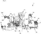
- a joining device 1 for manufacturing a product comprising a plurality of components (in this example a piece of furniture/furniture body) has a joining press 10 which is set up to join and press a plurality of components provided.
- the components are equipped with connecting elements, in particular with pins, wooden dowels, flat dowels, projections or the like, which can penetrate into corresponding recesses in an adjacent component.
- the components can be pressed using an adhesive in order to bring about a permanent connection.
- the joining device 1 comprises a first feed device 20, a second feed device 30, a third feed device 40, a fourth feed device 50, a fifth feed device 60 and a transport device 70.
- the feed devices are each set up to feed components so that the respective components are transferred to the joining press 10 and can be joined and pressed by the joining press.
- the joined subassembly is transported away from the joining press 10 by means of the removal device 70 .
- the first feed device 20 which is set up to provide side elements of a piece of furniture, is arranged in such a way that the components can be conveyed into the joining press 10 without changing direction.
- the first feed device 20 comprises a roller conveyor 21 for the individual provision of the side elements, which moves the side elements in a conveying direction R1.
- the second feed device 30 is arranged on a first side of the joining press 10 and at a distance from it.
- the second feed device 30 has a roller conveyor 31 which is arranged in such a way that the components moved by the roller conveyor 31, which in the exemplary embodiment are rear walls of the pieces of furniture to be manufactured, can be transferred to the joining press 10, as explained in more detail below.
- the second feeding device 30 provides a conveying movement with the roller conveyor 31 in a direction which is aligned parallel to that of the first feeding device 20 .
- the second feed device 30 is arranged at a distance from the first feed device 20 and the joining press 10 such that between the second feed device 30 on the one hand and the first Feeding device 20 and the joining press 10 on the other hand there is a free space.
- the joining device 1 also includes the third feed device 40, which, like the first feed device 20 and the second feed device 30, has a roller conveyor 41 for moving and providing individual components.
- the components provided by the third feed device 40 are bases of the pieces of furniture to be manufactured.
- the direction of movement specified by the roller conveyor 41 is parallel to that of the first feed device 20.
- the third feed device 40 is arranged, at least in sections, on a second side of the joining press 10, with the second side pointing in an opposite direction to the first side of the joining press 10.
- the third feed device 40 thus extends in sections parallel to the first feed device 20 and partially adjacent to the joining press 10.
- the joining device 1 comprises the fourth feeding device 50 which is arranged adjacent to the third feeding device 40 on the side facing away from the joining press 10 .
- the fifth feed device 60 is also provided in the embodiment, which provides these components in a direction opposite to the conveying directions of the first to fourth feed devices.
- the fifth feed device 60 comprises a belt conveyor 61.
- a first handling device 80 In the area between the fifth feed device 60 and the joining press 10 is a first handling device 80 arranged, which is set up to accept at least one component from the third feed device 40, the fourth feed device 50, or the fifth feed device 60 and to move it into the area of the joining press 10 and to transfer the component.
- the first handling device 80 is designed as a multi-axis robot, which is provided with a gripping device 85 for picking up and transferring a corresponding component.
- the gripping device 85 is designed as a multifunction gripper and includes suction sections 85a in order to pick up a panel-shaped component, such as a traverse strip, from the fourth feed device 50 . Furthermore, the gripping device 85 includes a clamping device 85b in order to receive a panel-shaped component, such as a floor, from the third feed device 40 .
- a second handling device 90 is arranged in an area between the second feed device 30 and the joining press 10 and is set up to pick up a component from the second feed device 30 and transfer it to the area of the joining press 10 .
- the second handling device 90 is designed as a multi-axis robot which has a second gripping device 95 .
- the second handling device 90 is set up, in particular, to accept a component (in particular a side part) from the first feed device 20 and to transfer it to a movable top pressure 12 of the joining press 10, and the second handling device 90 is set up to transfer another component (in particular a rear wall) to be taken over by the second feed device 30 and transferred to a pivoting device 17 of the joining press 10 .
- the top pressure 12 has a receiving device 12a, which can be moved along rails 12b of the top pressure into a processing area.
- the receiving device 12a has already been moved into the processing area.
- the receiving device 12a is moved to the projecting sections of the rails 12b.
- the gripping device 95 is designed as a multifunctional gripper and comprises a gripper 95a in order to pick up a panel-shaped component, in particular a side wall provided by the first feed device 20, and to transfer it to the top pressure 12. Another side wall provided with the first feed device 20 can be moved further to the joining press 10 by means of the first feed device 20 .
- the gripping device 95 includes suction clamps 95b in order to pick up a panel-shaped component, in particular a rear wall, from the second feed device 30 and transfer it to the pivoting device 17 of the joining press 10 .
- the transport device 70 is arranged on a side of the joining press 10 which is opposite to the first feed device 20 .
- the removal device 70 has a belt conveyor 71 with which the joined pieces of furniture can be moved away from the joining press 10 .
- the joining press 10 of the joining device 1 is described below.
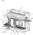
- the joining press 10 comprises a machine stand 11, on which the top pressure 12, which can be moved in the vertical direction, is attached.
- the top print 12 includes a receiving device for receiving a component (in particular a side wall), the receiving device being movable along the top print 12 .
- the joining press 10 comprises a conveyor device 13 which is designed as a belt conveyor in order to move one or more components, which are provided by the first feed device 20, into a processing area of the joining press 10.
- a table 14 is arranged in the processing area of the joining press 10, which table 14 holds or supports the component B2 (side element) fed with the conveyor device 13 during the pressing of an assembly.
- a first holding device 15 and a second holding device 16 are provided between the top pressure 12 and the table 14, which are set up to hold stationary workpieces before and while the assembly is pressed.
- the first holding device 15 has a first holding arm 15a and a second holding arm 15b, which are equipped with suction devices and hold a component B1 (here a floor) in an upright position.
- the holding arms 15a, 15b are attached to a first bracket 15c and are vertically movable along the bracket 15b.
- the first holding device 15 can thus be adapted to the size of the component to be held (here: component B1) by changing the distance between the holding arms 15a.
- the first holding device 15 can be moved in and counter to the conveying direction R1 along the machine stand 11 .
- the second holding device 16 is provided at a distance from the first holding device 15 in the conveying direction R1.
- the second holding device 16 comprises holding arms 16a, 16b which are attached to a second holder 16c and can be moved vertically along the second holder 16c in order to clamp components B3 (traversing strips) between the holding arms 16a, 16b and thus hold them upright.
- the second holder 16c can be moved along the machine stand 11 in and counter to the conveying direction R1.
- a distance between the first holding device 15 and the second holding device 16 can be varied.
- the joining press 10 includes the pivoting device 17, which is set up to receive a component (here: rear wall) and to feed it in a pivoting movement into an area above the table 14 and thus above a component provided on the table 14.
- a component here: rear wall
- the pivoting device comprises a first pickup arm 17a, a second pickup arm 17b and a joint 17c on which the first pickup arm 17a and the second pickup arm 17b are attached.
- the first pick-up arm 17a and the second pick-up arm 17b can each be moved independently of one another along the joint 17c and can thus be variably spaced from one another. It is thus possible to accommodate components of different sizes.
- first the third feed device 40 is used to feed in, so that this component can be gripped with the gripping device 85 of the first handling device.
- the first handling device moves the component into the area of the joining press and transfers the component to the second holding device 16.
- a component is fed into the joining press 10 in the conveying direction R1 by means of the first feed device 20 and arranged in such a way that the first and second holding devices 15, 16 hold the respective components above it Arrange horizontally aligned component or be arranged by a further movement of the first or second holding device 15, 16.
- a component is taken over from the first feed device 20 with the second handling device 90 by this component (particularly side wall) being gripped by the gripping device 95.
- the second handling device 90 transfers the component to the receiving device 12a for the top pressure 12 of the joining press 10.
- the receiving device 12a for the top pressure 12 is then moved in the conveying direction R1 into the processing area of the joining press 10.
- the second handling device 90 accepts another component (in particular the rear wall) from the second feed device 30 and transfers it to the pivoting device 17, which, after the second handling device 90 has transferred the component to the pivoting device 17, places the component in the Processing area of the joining press 10 feeds through a rotary movement.
- a further component can be taken over by the first handling device 80 and held in a region between the first holding device 15 and the second holding device 16 .
- the top pressure is then moved downwards in a vertical direction and the components are thus pressed into an assembly.
- This assembly can then be moved in the direction of the removal device 70 and removed accordingly from the joining press.
- the joining device is used for joining a piece of furniture or a furniture body, for example a kitchen element body
- the joining device can also be used for joining other assemblies.
Landscapes
- Engineering & Computer Science (AREA)
- Life Sciences & Earth Sciences (AREA)
- Wood Science & Technology (AREA)
- Forests & Forestry (AREA)
- Manufacturing & Machinery (AREA)
- Mechanical Engineering (AREA)
- Automatic Assembly (AREA)
- Furniture Connections (AREA)
Applications Claiming Priority (1)
| Application Number | Priority Date | Filing Date | Title |
|---|---|---|---|
| DE102021101750.5A DE102021101750A1 (de) | 2021-01-27 | 2021-01-27 | Fügeeinrichtung sowie Verfahren |
Publications (3)
| Publication Number | Publication Date |
|---|---|
| EP4046764A2 true EP4046764A2 (fr) | 2022-08-24 |
| EP4046764A3 EP4046764A3 (fr) | 2022-11-02 |
| EP4046764B1 EP4046764B1 (fr) | 2024-08-14 |
Family
ID=80122059
Family Applications (1)
| Application Number | Title | Priority Date | Filing Date |
|---|---|---|---|
| EP22153171.8A Active EP4046764B1 (fr) | 2021-01-27 | 2022-01-25 | Dispositif d'assemblage, ainsi que procédé |
Country Status (3)
| Country | Link |
|---|---|
| EP (1) | EP4046764B1 (fr) |
| DE (1) | DE102021101750A1 (fr) |
| PL (1) | PL4046764T3 (fr) |
Families Citing this family (1)
| Publication number | Priority date | Publication date | Assignee | Title |
|---|---|---|---|---|
| CN118003081B (zh) * | 2024-04-10 | 2024-06-07 | 德魁智能装备(苏州)有限公司 | 床芯自动化组装线 |
Family Cites Families (10)
| Publication number | Priority date | Publication date | Assignee | Title |
|---|---|---|---|---|
| DE19637178C2 (de) * | 1996-09-12 | 1998-08-06 | Fraunhofer Ges Forschung | Pressenvorrichtung zur Herstellung von Gestellmöbeln |
| DE19652756C1 (de) * | 1996-12-18 | 1998-10-22 | Huettenhoelscher Maschinenbau | Vorrichtung zum Zusammenfügen von Möbelkorpussen |
| DE19903458A1 (de) | 1999-01-28 | 2000-08-03 | Roland Fischer | Anordnung und Verfahren zur Montage von Möbelstücken |
| DE29924143U1 (de) * | 1999-04-19 | 2002-03-28 | Ligmatech Maschinenbau GmbH, 09638 Lichtenberg | Möbelkorpus-Montagelinie |
| DE202005020526U1 (de) | 2005-05-20 | 2006-03-23 | Ligmatech Automationssysteme Gmbh | Montagelinie |
| DE102006036193B4 (de) * | 2006-08-01 | 2008-04-24 | Prieß, Horstmann & Co Maschinenbau GmbH & Co KG | Vorrichtung und Verfahren zur Montage eines Möbelkorpus |
| DE102013001472B4 (de) * | 2013-01-29 | 2016-03-31 | Hüttenhölscher Maschinenbau GmbH & Co. KG | Verfahren und Anordnung zur Montage einer Möbelrückwand |
| DE202014101000U1 (de) | 2014-03-06 | 2015-06-12 | Kuka Systems Gmbh | Fügewerkzeug und Fügeeinrichtung |
| DE102014208519A1 (de) | 2014-05-07 | 2015-11-12 | Homag Holzbearbeitungssysteme Gmbh | Bearbeitungsvorrichtung und Bearbeitungsverfahren |
| DE102016007010B4 (de) | 2016-06-09 | 2024-08-01 | Hüttenhölscher Maschinenbau GmbH & Co. KG | Zuführeinrichtung für Möbelteile zu einer Zusammenfügeeinrichtung |
-
2021
- 2021-01-27 DE DE102021101750.5A patent/DE102021101750A1/de active Pending
-
2022
- 2022-01-25 EP EP22153171.8A patent/EP4046764B1/fr active Active
- 2022-01-25 PL PL22153171.8T patent/PL4046764T3/pl unknown
Also Published As
| Publication number | Publication date |
|---|---|
| DE102021101750A1 (de) | 2022-07-28 |
| EP4046764B1 (fr) | 2024-08-14 |
| PL4046764T3 (pl) | 2024-11-25 |
| EP4046764A3 (fr) | 2022-11-02 |
Similar Documents
| Publication | Publication Date | Title |
|---|---|---|
| EP3391987B1 (fr) | Procédé de soudage de parties de tôles découpées | |
| EP3140076B1 (fr) | Dispositif d'usinage et procédé d'usinage | |
| EP4041501B1 (fr) | Procédé pour transporter et/ou manipuler des pièces | |
| EP2546153B1 (fr) | Dispositif et procédé pour empiler des pièces empilables | |
| AT514870B1 (de) | Anlage zur Bearbeitung von Platten oder Werkstücken aus Holz und Ähnlichem, Bearbeitungsmodul und entsprechende Bearbeitungsverfahren | |
| DE102017121557B4 (de) | Verfahren und Vorrichtung zur Förderung und Positionierung von Werkstücken | |
| EP3140077B1 (fr) | Système de machine-outil et procédé pour faire fonctionner un système de machine-outil | |
| DE112016002792T5 (de) | Reckwalzmaschine und Reckwalzverfahren | |
| DE3622922C2 (fr) | ||
| DE10008109A1 (de) | Verfahren und Vorrichtung zum Herstellen einer DVD | |
| EP4046764B1 (fr) | Dispositif d'assemblage, ainsi que procédé | |
| DE102019107077B4 (de) | Förderanlage zum Umsetzen zumindest eines plattenförmigen Werkstücks | |
| WO2020239154A1 (fr) | Cellule de fabrication à cadence élevée | |
| AT522859B1 (de) | Übergabeverfahren, dafür ausgebildetes Manipulationssystem sowie Biegeanlage | |
| EP2949439B1 (fr) | Dispositif de traitement et procédé de traitement | |
| EP4166864B1 (fr) | Procédé et dispositif de montage pour le montage automatisé d'un cadre pour un élément de conduit d'air | |
| EP3621906B1 (fr) | Dispositif de préhension pour soulever un produit semi-fini flexible d'un support et procédé correspondant | |
| DE102023112439A1 (de) | Fördereinrichtung | |
| DE102020108037B4 (de) | Positionierungseinrichtung und Verfahren zur Positionierung von Werkstücken | |
| EP3421151A1 (fr) | Procédé de traitement de découpes à partir d'un matériau en forme de plaque | |
| EP3624989A1 (fr) | Dispositif d'alimentation et procédé d'alimentation | |
| EP4193390A1 (fr) | Procédé et appareil de fabrication de panneaux solaires | |
| EP3951039B1 (fr) | Dispositif d'alimentation pour machines à coudre destiné au chargement automatique d'une machine à coudre en pièce à coudre | |
| AT526774B1 (de) | Pult zur Ablage eines Werkstücks aus Blech | |
| WO2017114632A1 (fr) | Procédé et dispositif de placement de feuilles de placage |
Legal Events
| Date | Code | Title | Description |
|---|---|---|---|
| PUAI | Public reference made under article 153(3) epc to a published international application that has entered the european phase |
Free format text: ORIGINAL CODE: 0009012 |
|
| STAA | Information on the status of an ep patent application or granted ep patent |
Free format text: STATUS: THE APPLICATION HAS BEEN PUBLISHED |
|
| AK | Designated contracting states |
Kind code of ref document: A2 Designated state(s): AL AT BE BG CH CY CZ DE DK EE ES FI FR GB GR HR HU IE IS IT LI LT LU LV MC MK MT NL NO PL PT RO RS SE SI SK SM TR |
|
| PUAL | Search report despatched |
Free format text: ORIGINAL CODE: 0009013 |
|
| RIC1 | Information provided on ipc code assigned before grant |
Ipc: B27M 3/18 20060101AFI20220921BHEP |
|
| AK | Designated contracting states |
Kind code of ref document: A3 Designated state(s): AL AT BE BG CH CY CZ DE DK EE ES FI FR GB GR HR HU IE IS IT LI LT LU LV MC MK MT NL NO PL PT RO RS SE SI SK SM TR |
|
| RIC1 | Information provided on ipc code assigned before grant |
Ipc: B27M 3/18 20060101AFI20220926BHEP |
|
| STAA | Information on the status of an ep patent application or granted ep patent |
Free format text: STATUS: REQUEST FOR EXAMINATION WAS MADE |
|
| 17P | Request for examination filed |
Effective date: 20230329 |
|
| RBV | Designated contracting states (corrected) |
Designated state(s): AL AT BE BG CH CY CZ DE DK EE ES FI FR GB GR HR HU IE IS IT LI LT LU LV MC MK MT NL NO PL PT RO RS SE SI SK SM TR |
|
| P01 | Opt-out of the competence of the unified patent court (upc) registered |
Effective date: 20230529 |
|
| STAA | Information on the status of an ep patent application or granted ep patent |
Free format text: STATUS: EXAMINATION IS IN PROGRESS |
|
| 17Q | First examination report despatched |
Effective date: 20230818 |
|
| REG | Reference to a national code |
Ref country code: DE Ref legal event code: R079 Free format text: PREVIOUS MAIN CLASS: B27M0003180000 Ipc: B27M0001080000 Ref document number: 502022001423 Country of ref document: DE |
|
| GRAP | Despatch of communication of intention to grant a patent |
Free format text: ORIGINAL CODE: EPIDOSNIGR1 |
|
| STAA | Information on the status of an ep patent application or granted ep patent |
Free format text: STATUS: GRANT OF PATENT IS INTENDED |
|
| INTG | Intention to grant announced |
Effective date: 20240314 |
|
| RIC1 | Information provided on ipc code assigned before grant |
Ipc: F16B 12/04 20060101ALI20240301BHEP Ipc: B27M 3/00 20060101ALI20240301BHEP Ipc: B27M 3/18 20060101ALI20240301BHEP Ipc: B27M 1/08 20060101AFI20240301BHEP |
|
| GRAS | Grant fee paid |
Free format text: ORIGINAL CODE: EPIDOSNIGR3 |
|
| GRAA | (expected) grant |
Free format text: ORIGINAL CODE: 0009210 |
|
| STAA | Information on the status of an ep patent application or granted ep patent |
Free format text: STATUS: THE PATENT HAS BEEN GRANTED |
|
| AK | Designated contracting states |
Kind code of ref document: B1 Designated state(s): AL AT BE BG CH CY CZ DE DK EE ES FI FR GB GR HR HU IE IS IT LI LT LU LV MC MK MT NL NO PL PT RO RS SE SI SK SM TR |
|
| REG | Reference to a national code |
Ref country code: GB Ref legal event code: FG4D Free format text: NOT ENGLISH |
|
| REG | Reference to a national code |
Ref country code: CH Ref legal event code: EP |
|
| REG | Reference to a national code |
Ref country code: DE Ref legal event code: R096 Ref document number: 502022001423 Country of ref document: DE |
|
| REG | Reference to a national code |
Ref country code: IE Ref legal event code: FG4D Free format text: LANGUAGE OF EP DOCUMENT: GERMAN |
|
| REG | Reference to a national code |
Ref country code: LT Ref legal event code: MG9D |
|
| REG | Reference to a national code |
Ref country code: NL Ref legal event code: MP Effective date: 20240814 |
|
| PG25 | Lapsed in a contracting state [announced via postgrant information from national office to epo] |
Ref country code: NO Free format text: LAPSE BECAUSE OF FAILURE TO SUBMIT A TRANSLATION OF THE DESCRIPTION OR TO PAY THE FEE WITHIN THE PRESCRIBED TIME-LIMIT Effective date: 20241114 |
|
| PG25 | Lapsed in a contracting state [announced via postgrant information from national office to epo] |
Ref country code: NL Free format text: LAPSE BECAUSE OF FAILURE TO SUBMIT A TRANSLATION OF THE DESCRIPTION OR TO PAY THE FEE WITHIN THE PRESCRIBED TIME-LIMIT Effective date: 20240814 Ref country code: PT Free format text: LAPSE BECAUSE OF FAILURE TO SUBMIT A TRANSLATION OF THE DESCRIPTION OR TO PAY THE FEE WITHIN THE PRESCRIBED TIME-LIMIT Effective date: 20241216 Ref country code: GR Free format text: LAPSE BECAUSE OF FAILURE TO SUBMIT A TRANSLATION OF THE DESCRIPTION OR TO PAY THE FEE WITHIN THE PRESCRIBED TIME-LIMIT Effective date: 20241115 Ref country code: FI Free format text: LAPSE BECAUSE OF FAILURE TO SUBMIT A TRANSLATION OF THE DESCRIPTION OR TO PAY THE FEE WITHIN THE PRESCRIBED TIME-LIMIT Effective date: 20240814 |
|
| PG25 | Lapsed in a contracting state [announced via postgrant information from national office to epo] |
Ref country code: BG Free format text: LAPSE BECAUSE OF FAILURE TO SUBMIT A TRANSLATION OF THE DESCRIPTION OR TO PAY THE FEE WITHIN THE PRESCRIBED TIME-LIMIT Effective date: 20240814 |
|
| PG25 | Lapsed in a contracting state [announced via postgrant information from national office to epo] |
Ref country code: LV Free format text: LAPSE BECAUSE OF FAILURE TO SUBMIT A TRANSLATION OF THE DESCRIPTION OR TO PAY THE FEE WITHIN THE PRESCRIBED TIME-LIMIT Effective date: 20240814 |
|
| PG25 | Lapsed in a contracting state [announced via postgrant information from national office to epo] |
Ref country code: IS Free format text: LAPSE BECAUSE OF FAILURE TO SUBMIT A TRANSLATION OF THE DESCRIPTION OR TO PAY THE FEE WITHIN THE PRESCRIBED TIME-LIMIT Effective date: 20241214 |
|
| PG25 | Lapsed in a contracting state [announced via postgrant information from national office to epo] |
Ref country code: HR Free format text: LAPSE BECAUSE OF FAILURE TO SUBMIT A TRANSLATION OF THE DESCRIPTION OR TO PAY THE FEE WITHIN THE PRESCRIBED TIME-LIMIT Effective date: 20240814 |
|
| PG25 | Lapsed in a contracting state [announced via postgrant information from national office to epo] |
Ref country code: RS Free format text: LAPSE BECAUSE OF FAILURE TO SUBMIT A TRANSLATION OF THE DESCRIPTION OR TO PAY THE FEE WITHIN THE PRESCRIBED TIME-LIMIT Effective date: 20241114 Ref country code: ES Free format text: LAPSE BECAUSE OF FAILURE TO SUBMIT A TRANSLATION OF THE DESCRIPTION OR TO PAY THE FEE WITHIN THE PRESCRIBED TIME-LIMIT Effective date: 20240814 |
|
| PG25 | Lapsed in a contracting state [announced via postgrant information from national office to epo] |
Ref country code: RS Free format text: LAPSE BECAUSE OF FAILURE TO SUBMIT A TRANSLATION OF THE DESCRIPTION OR TO PAY THE FEE WITHIN THE PRESCRIBED TIME-LIMIT Effective date: 20241114 Ref country code: PT Free format text: LAPSE BECAUSE OF FAILURE TO SUBMIT A TRANSLATION OF THE DESCRIPTION OR TO PAY THE FEE WITHIN THE PRESCRIBED TIME-LIMIT Effective date: 20241216 Ref country code: NO Free format text: LAPSE BECAUSE OF FAILURE TO SUBMIT A TRANSLATION OF THE DESCRIPTION OR TO PAY THE FEE WITHIN THE PRESCRIBED TIME-LIMIT Effective date: 20241114 Ref country code: NL Free format text: LAPSE BECAUSE OF FAILURE TO SUBMIT A TRANSLATION OF THE DESCRIPTION OR TO PAY THE FEE WITHIN THE PRESCRIBED TIME-LIMIT Effective date: 20240814 Ref country code: LV Free format text: LAPSE BECAUSE OF FAILURE TO SUBMIT A TRANSLATION OF THE DESCRIPTION OR TO PAY THE FEE WITHIN THE PRESCRIBED TIME-LIMIT Effective date: 20240814 Ref country code: IS Free format text: LAPSE BECAUSE OF FAILURE TO SUBMIT A TRANSLATION OF THE DESCRIPTION OR TO PAY THE FEE WITHIN THE PRESCRIBED TIME-LIMIT Effective date: 20241214 Ref country code: HR Free format text: LAPSE BECAUSE OF FAILURE TO SUBMIT A TRANSLATION OF THE DESCRIPTION OR TO PAY THE FEE WITHIN THE PRESCRIBED TIME-LIMIT Effective date: 20240814 Ref country code: GR Free format text: LAPSE BECAUSE OF FAILURE TO SUBMIT A TRANSLATION OF THE DESCRIPTION OR TO PAY THE FEE WITHIN THE PRESCRIBED TIME-LIMIT Effective date: 20241115 Ref country code: FI Free format text: LAPSE BECAUSE OF FAILURE TO SUBMIT A TRANSLATION OF THE DESCRIPTION OR TO PAY THE FEE WITHIN THE PRESCRIBED TIME-LIMIT Effective date: 20240814 Ref country code: ES Free format text: LAPSE BECAUSE OF FAILURE TO SUBMIT A TRANSLATION OF THE DESCRIPTION OR TO PAY THE FEE WITHIN THE PRESCRIBED TIME-LIMIT Effective date: 20240814 Ref country code: BG Free format text: LAPSE BECAUSE OF FAILURE TO SUBMIT A TRANSLATION OF THE DESCRIPTION OR TO PAY THE FEE WITHIN THE PRESCRIBED TIME-LIMIT Effective date: 20240814 |
|
| PG25 | Lapsed in a contracting state [announced via postgrant information from national office to epo] |
Ref country code: DK Free format text: LAPSE BECAUSE OF FAILURE TO SUBMIT A TRANSLATION OF THE DESCRIPTION OR TO PAY THE FEE WITHIN THE PRESCRIBED TIME-LIMIT Effective date: 20240814 Ref country code: SM Free format text: LAPSE BECAUSE OF FAILURE TO SUBMIT A TRANSLATION OF THE DESCRIPTION OR TO PAY THE FEE WITHIN THE PRESCRIBED TIME-LIMIT Effective date: 20240814 Ref country code: RO Free format text: LAPSE BECAUSE OF FAILURE TO SUBMIT A TRANSLATION OF THE DESCRIPTION OR TO PAY THE FEE WITHIN THE PRESCRIBED TIME-LIMIT Effective date: 20240814 |
|
| PG25 | Lapsed in a contracting state [announced via postgrant information from national office to epo] |
Ref country code: EE Free format text: LAPSE BECAUSE OF FAILURE TO SUBMIT A TRANSLATION OF THE DESCRIPTION OR TO PAY THE FEE WITHIN THE PRESCRIBED TIME-LIMIT Effective date: 20240814 |
|
| PG25 | Lapsed in a contracting state [announced via postgrant information from national office to epo] |
Ref country code: CZ Free format text: LAPSE BECAUSE OF FAILURE TO SUBMIT A TRANSLATION OF THE DESCRIPTION OR TO PAY THE FEE WITHIN THE PRESCRIBED TIME-LIMIT Effective date: 20240814 |
|
| PG25 | Lapsed in a contracting state [announced via postgrant information from national office to epo] |
Ref country code: SK Free format text: LAPSE BECAUSE OF FAILURE TO SUBMIT A TRANSLATION OF THE DESCRIPTION OR TO PAY THE FEE WITHIN THE PRESCRIBED TIME-LIMIT Effective date: 20240814 |
|
| REG | Reference to a national code |
Ref country code: DE Ref legal event code: R097 Ref document number: 502022001423 Country of ref document: DE |
|
| PLBE | No opposition filed within time limit |
Free format text: ORIGINAL CODE: 0009261 |
|
| STAA | Information on the status of an ep patent application or granted ep patent |
Free format text: STATUS: NO OPPOSITION FILED WITHIN TIME LIMIT |
|
| 26N | No opposition filed |
Effective date: 20250515 |
|
| REG | Reference to a national code |
Ref country code: CH Ref legal event code: PL |
|
| PG25 | Lapsed in a contracting state [announced via postgrant information from national office to epo] |
Ref country code: SE Free format text: LAPSE BECAUSE OF FAILURE TO SUBMIT A TRANSLATION OF THE DESCRIPTION OR TO PAY THE FEE WITHIN THE PRESCRIBED TIME-LIMIT Effective date: 20240814 |
|
| PG25 | Lapsed in a contracting state [announced via postgrant information from national office to epo] |
Ref country code: LU Free format text: LAPSE BECAUSE OF NON-PAYMENT OF DUE FEES Effective date: 20250125 Ref country code: MC Free format text: LAPSE BECAUSE OF FAILURE TO SUBMIT A TRANSLATION OF THE DESCRIPTION OR TO PAY THE FEE WITHIN THE PRESCRIBED TIME-LIMIT Effective date: 20240814 |
|
| PG25 | Lapsed in a contracting state [announced via postgrant information from national office to epo] |
Ref country code: BE Free format text: LAPSE BECAUSE OF NON-PAYMENT OF DUE FEES Effective date: 20250131 |
|
| PG25 | Lapsed in a contracting state [announced via postgrant information from national office to epo] |
Ref country code: CH Free format text: LAPSE BECAUSE OF NON-PAYMENT OF DUE FEES Effective date: 20250131 |
|
| REG | Reference to a national code |
Ref country code: BE Ref legal event code: MM Effective date: 20250131 |
|
| PG25 | Lapsed in a contracting state [announced via postgrant information from national office to epo] |
Ref country code: IE Free format text: LAPSE BECAUSE OF NON-PAYMENT OF DUE FEES Effective date: 20250125 |
|
| PGFP | Annual fee paid to national office [announced via postgrant information from national office to epo] |
Ref country code: PL Payment date: 20251216 Year of fee payment: 5 |
|
| PGFP | Annual fee paid to national office [announced via postgrant information from national office to epo] |
Ref country code: DE Payment date: 20260122 Year of fee payment: 5 |
|
| PGFP | Annual fee paid to national office [announced via postgrant information from national office to epo] |
Ref country code: AT Payment date: 20260301 Year of fee payment: 5 |
|
| PGFP | Annual fee paid to national office [announced via postgrant information from national office to epo] |
Ref country code: IT Payment date: 20260130 Year of fee payment: 5 |
|
| PGFP | Annual fee paid to national office [announced via postgrant information from national office to epo] |
Ref country code: FR Payment date: 20260122 Year of fee payment: 5 |