EP4046764B1 - Fügeeinrichtung sowie verfahren - Google Patents
Fügeeinrichtung sowie verfahren Download PDFInfo
- Publication number
- EP4046764B1 EP4046764B1 EP22153171.8A EP22153171A EP4046764B1 EP 4046764 B1 EP4046764 B1 EP 4046764B1 EP 22153171 A EP22153171 A EP 22153171A EP 4046764 B1 EP4046764 B1 EP 4046764B1
- Authority
- EP
- European Patent Office
- Prior art keywords
- joining
- press
- component
- joining press
- handling device
- Prior art date
- Legal status (The legal status is an assumption and is not a legal conclusion. Google has not performed a legal analysis and makes no representation as to the accuracy of the status listed.)
- Active
Links
Images


Classifications
-
- B—PERFORMING OPERATIONS; TRANSPORTING
- B27—WORKING OR PRESERVING WOOD OR SIMILAR MATERIAL; NAILING OR STAPLING MACHINES IN GENERAL
- B27M—WORKING OF WOOD NOT PROVIDED FOR IN SUBCLASSES B27B - B27L; MANUFACTURE OF SPECIFIC WOODEN ARTICLES
- B27M3/00—Manufacture or reconditioning of specific semi-finished or finished articles
- B27M3/18—Manufacture or reconditioning of specific semi-finished or finished articles of furniture or of doors
-
- B—PERFORMING OPERATIONS; TRANSPORTING
- B27—WORKING OR PRESERVING WOOD OR SIMILAR MATERIAL; NAILING OR STAPLING MACHINES IN GENERAL
- B27M—WORKING OF WOOD NOT PROVIDED FOR IN SUBCLASSES B27B - B27L; MANUFACTURE OF SPECIFIC WOODEN ARTICLES
- B27M1/00—Working of wood not provided for in subclasses B27B - B27L, e.g. by stretching
- B27M1/08—Working of wood not provided for in subclasses B27B - B27L, e.g. by stretching by multi-step processes
-
- B—PERFORMING OPERATIONS; TRANSPORTING
- B27—WORKING OR PRESERVING WOOD OR SIMILAR MATERIAL; NAILING OR STAPLING MACHINES IN GENERAL
- B27M—WORKING OF WOOD NOT PROVIDED FOR IN SUBCLASSES B27B - B27L; MANUFACTURE OF SPECIFIC WOODEN ARTICLES
- B27M3/00—Manufacture or reconditioning of specific semi-finished or finished articles
- B27M3/0013—Manufacture or reconditioning of specific semi-finished or finished articles of composite or compound articles
- B27M3/0073—Manufacture or reconditioning of specific semi-finished or finished articles of composite or compound articles characterised by nailing, stapling or screwing connections
-
- F—MECHANICAL ENGINEERING; LIGHTING; HEATING; WEAPONS; BLASTING
- F16—ENGINEERING ELEMENTS AND UNITS; GENERAL MEASURES FOR PRODUCING AND MAINTAINING EFFECTIVE FUNCTIONING OF MACHINES OR INSTALLATIONS; THERMAL INSULATION IN GENERAL
- F16B—DEVICES FOR FASTENING OR SECURING CONSTRUCTIONAL ELEMENTS OR MACHINE PARTS TOGETHER, e.g. NAILS, BOLTS, CIRCLIPS, CLAMPS, CLIPS OR WEDGES; JOINTS OR JOINTING
- F16B12/00—Jointing of furniture or the like, e.g. hidden from exterior
- F16B12/04—Non-loosenable joints for non-metal furniture parts, e.g. glued
Definitions
- the invention relates to a joining device for joining an assembly, in particular a piece of furniture comprising several components, and to a method for joining an assembly.
- a joining device for joining an assembly, in particular a piece of furniture comprising several components, and to a method for joining an assembly.
- Such a joining device is used in particular in the wood processing industry, for example in furniture production.
- joining presses are known for furniture production, with which components of furniture can be joined together.
- shelves, cupboards or drawers can be made with such a joining press, whereby the components to be joined are side walls, floors, cover panels or similar of such a piece of furniture.
- the invention is based on the object of providing a joining device which enables increased flexibility with high productivity.
- Claims 1 and 10 provide a corresponding joining device and the associated method. Further preferred embodiments are listed in the dependent claims.
- the DE10 2013 00147284 discloses relevant prior art.
- the DE19652756C1 reveals the preamble of the main claim.
- a joining device which comprises: a joining press which is configured to join components to form an assembly in a processing area, wherein the joining press has a first side and a second side, wherein the first side and the second side are different sides of the joining press.
- the first and second sides of the joining press can be opposite sides of the joining press.
- the joining device further comprises a first handling device which is configured to move at least one component to the first side of the joining press, and a second handling device which is configured to move at least one further component to the second side of the joining press to the processing area of the joining press.
- the invention offers the possibility of producing assemblies, such as furniture, with high performance and high flexibility.
- the use of the handling devices offers the advantage that components can be transferred to the joining press quickly and/or in the correct position. It also opens up the possibility of holding individual components, such as special parts, with the handling device during the joining process. This also reduces the complexity of the joining press itself, because the holding devices of the joining press do not have to be able to accommodate and hold all the different components.
- the joining device can be used, for example, to join pieces of furniture, such as furniture bodies, kitchen cabinets or similar.
- the advantage of the joining device is that all components can be fed flexibly, so that a wide variety of variants can be produced, for example at an output of around three bodies per minute. This also allows assemblies to be joined that cannot be assigned to a standard design. In furniture production, for example, these are bodies with central posts, central sides, front panels or cross members in atypical positions.
- a “processing area" of the joining press is an area of the joining press in which a joining process is carried out.
- a processing area of the joining press is located at least partially between an upper pressure and a table of the joining press.
- the first handling device is configured to move at least one component into the processing area of the joining press or into an area adjacent to the processing area of the joining press, and/or that the second handling device is configured to move at least one component into the processing area of the joining press or into an area adjacent to the processing area of the joining press.
- the second handling device can transfer the component, preferably a rear wall, to a feed device of the joining press, in particular a pivoting device of the joining press, wherein the feed device moves the component into the processing area, in particular pivots it.
- the second handling device can be designed to transfer a component, in particular a side wall, to a receiving device of an upper pressure of the joining press.
- the receiving device can be movable from an area adjacent to the processing area into the processing area.
- the receiving device of the upper pressure is moved to sections of the rails pointing in the direction of a first feed device in order to take over a component from the second handling device.
- first handling device and/or the second handling device can receive and hold at least one component.
- first handling device and/or the second handling device comprises a robot or robot arm.
- first side and the second side of the joining press are opposite sides, with a conveying direction of components through the joining press running from a third side to a fourth side of the joining press. Components can thus be fed to the joining press from the side using the handling devices.
- the joining device comprises a first feed device which is arranged in such a way that components can be conveyed directly into the joining press. Components are thus transferred from the first feed device to the joining press.
- the first feed device can, for example, have a roller conveyor which transfers the components accordingly to the joining press.
- the first feed device is provided on a third side of the joining press, wherein the third side is provided between the first and second sides of the joining press. It is thus possible to Handling devices feed components from the first and second side, whereas the first feed device feeds components from the third side into the joining press. This enables a particularly high cycle rate.
- the joining device has a second feed device, which is arranged in such a way that the second handling device can take over a component provided by the second feed device and move it into the processing area of the joining press. Components can thus be fed individually and made available for takeover by the second handling device.
- the joining device comprises a third feed device, which is arranged in such a way that the first handling device can take over a component provided by the third feed device and move it into the processing area of the joining press. In this way, components can be fed individually and accordingly made available for transfer by the first handling device.
- the joining device comprises a fourth feed device and/or a fifth feed device, which is/are arranged in such a way that the first handling device can take over components provided by the fourth and/or fifth feed device and move them into the processing area of the joining press.
- the first handling device can take over components provided by the fourth and/or fifth feed device and move them into the processing area of the joining press.
- the first handling device can take over components provided by the fourth and/or fifth feed device and move them into the processing area of the joining press.
- the first handling device can take over components provided by the fourth and/or fifth feed device and move them into the processing area of the joining press.
- the first handling device can take over components provided by the fourth and/or fifth feed device and move them into the processing area of the joining press.
- the feed devices are designed for different components.
- the first handling device and/or the second handling device is/are designed as a multi-axis robot, in particular as a six-axis robot.
- Complete movement processes can be carried out with a multi-axis robot.
- special components can also be used for a joining process.
- the first handling device and/or the second handling device has/have several gripping devices or a multifunctional gripper, which for example has a vacuum suction device, suction clamp, mechanical gripper, a clamping gripper or the like.
- gripping devices of the handling device(s) are selected from: one or more suction sections, a clamping device, a gripper, such as gripping tongs, and a suction clamp. The handling devices can thus be used flexibly for different components and for different handling tasks.
- the first handling device and/or the second handling device is/are configured to hold a component during a joining process of the joining press.
- the complexity of the joining press can thus be reduced because the respective handling device is drawn into the joining process.
- the joining press has a conveying device with a conveying direction from a third side to a fourth side of the joining press. This defines a conveying direction to which the Handling devices can feed a component from each side. This ensures a particularly high cycle time and at the same time a high level of flexibility of the joining device.
- the joining press can comprise a pivoting device for receiving a component provided by the second handling device, in particular a rear wall of a body, and/or a first holding device and a second holding device, wherein the first holding device and the second holding device are each designed to hold a standing component.
- the holding of the standing component can take place before or during pressing of the assembly.
- the components that are held by means of the first and/or second holding device can be body components.
- a joining device comprising: a joining press which is configured to join components to form an assembly, wherein the joining press has a first side and a second side, wherein the first side and the second side are different, in particular opposite, sides of the joining press, and a first handling device which is configured to move at least one component from the first side of the joining press to the joining press, wherein the first handling device is configured to receive at least two components.
- the joining device according to this objective can, according to further embodiments, have one or more features according to the aspects listed above.
- the joining device according to this objective can have a second handling device which is designed to remove at least one further component from the second side of the joining press to the processing area of the joining press.
- a joining device which comprises: a joining press which is configured to join components to form an assembly, wherein the joining press has a first side and a second side, wherein the first side and the second side are different, in particular opposite, sides of the joining press, and a first handling device which is configured to move at least one component from the first side of the joining press to the joining press, wherein the first handling device has a gripping device with a plurality of receiving sections for receiving components.
- the joining device according to this objective can have one or more features according to the aspects listed above.
- the joining device according to this objective can have a second handling device that is designed to move at least one further component from the second side of the joining press to the processing area of the joining press.
- a method for joining an assembly made up of several components using a joining press comprises the following steps: feeding a component by means of a first handling device to a first side of the joining press, in particular into a processing area of the joining press, and feeding a further component by means of a second handling device to a second side of the joining press to a processing area of the joining press, wherein the first side and the second side are different, in particular opposite, sides of the joining press.
- the process can be used to manufacture a piece of furniture, such as a furniture body. This increases the flexibility when manufacturing a piece of furniture.
- first side and the second side of the joining press are opposite sides, with a conveying direction of components through the joining press running from a third side to a fourth side of the joining press. Components can thus be fed to the joining press from the side using the handling devices.
- a component is fed to the joining press from a third side of the joining press by means of a first feeding device.
- the components fed by the first handling device from a first side of the joining press into a processing area and by the second handling device from a second side of the joining press into a processing area of the joining press can thus be combined and joined accordingly.
- first handling device and/or the second handling device hold a component during a joining process of the joining press.
- special components can also be used for a joining process, thus increasing flexibility.
- a conveying direction from a third side to a fourth side of the joining press is provided. In the conveying direction, the assembled assembly is moved. This ensures a high throughput.
- a joining device 1 for manufacturing a product comprising several components has a joining press 10 which is set up to join and press several provided components.
- the components are equipped with connecting elements, in particular with pins, wooden dowels, flat dowels, projections or the like, which can penetrate into corresponding recesses of an adjacent component.
- the components can be pressed together using an adhesive in order to bring about a permanent connection.
- the joining device 1 comprises a first feed device 20, a second feed device 30, a third feed device 40, a fourth feed device 50, a fifth feed device 60 and a removal device 70.
- the feed devices are each set up to feed components so that the respective components can be transferred to the joining press 10 and joined and pressed by the joining press.
- the joined assembly is transported away from the joining press 10 by means of the removal device 70.
- the first feed device 20 which is designed to provide side elements of a piece of furniture, is arranged such that the components can be conveyed into the joining press 10 without changing direction.
- the first feed device 20 comprises a roller conveyor 21 for individually providing the side elements, which moves the side elements in a conveying direction R1.
- the second feed device 30 is arranged on a first side of the joining press 10 and at a distance from it.
- the second feed device 30 has a roller conveyor 31 which is arranged in such a way that the components moved by the roller conveyor 31, which in the exemplary embodiment are the back walls of the pieces of furniture to be manufactured, can be transferred to the joining press 10, as explained in more detail below.
- the second feed device 30 provides a conveying movement with the roller conveyor 31 in a direction that is aligned parallel to that of the first feed device 20.
- the second feed device 30 is arranged at a distance from the first feed device 20 and from the joining press 10 in such a way that between the second feed device 30 on the one hand and the first There is free space between the feeding device 20 and the joining press 10 on the other hand.
- the joining device 1 further comprises the third feed device 40, which, similar to the first feed device 20 and the second feed device 30, has a roller conveyor 41 for moving and providing individual components.
- the components provided by the third feed device 40 are the bases of the pieces of furniture to be manufactured.
- the direction of movement specified by the roller conveyor 41 is parallel to that of the first feed device 20.
- the third feed device 40 is arranged, at least in sections, on a second side of the joining press 10, wherein the second side points in an opposite direction to the first side of the joining press 10.
- the third feed device 40 extends in sections parallel to the first feed device 20 and in sections adjacent to the joining press 10.
- the joining device 1 comprises the fourth feed device 50, which is arranged adjacent to the third feed device 40 on the side facing away from the joining press 10.
- the embodiment also provides the fifth feed device 60, which provides these components in a direction opposite to the conveying directions of the first to fourth feed devices.
- the fifth feed device 60 comprises a belt conveyor 61 for this purpose.
- a first handling device 80 which is designed to take at least one component from the third feed device 40, the fourth feed device 50, or the fifth feed device 60 and to move it into the area of the joining press 10 and to transfer the component.
- the first handling device 80 is designed as a multi-axis robot, which is provided with a gripping device 85 for picking up and transferring a corresponding component.
- the gripping device 85 is designed as a multifunctional gripper and comprises suction sections 85a in order to pick up a plate-shaped component, such as a traverse strip, from the fourth feed device 50. Furthermore, the gripping device 85 comprises a clamping device 85b in order to pick up a plate-shaped component, such as a base, from the third feed device 40.
- a second handling device 90 is arranged, which is set up to pick up a component from the second feed device 30 and to transfer it in the area of the joining press 10.
- the second handling device 90 is designed as a multi-axis robot, which has a second gripping device 95.
- the second handling device 90 is in particular designed to take over a component (in particular a side part) from the first feed device 20 and to transfer it to a movable upper pressure 12 of the joining press 10, and the second handling device 90 is designed to take over a further component (in particular a rear wall) from the second feed device 30 and to transfer it to a pivoting device 17 of the joining press 10.
- the upper pressure 12 has a receiving device 12a, which can be moved along rails 12b of the upper pressure into a processing area.
- the receiving device 12a has already been moved into the processing area.
- the receiving device 12a is moved to the projecting sections of the rails 12b.
- the gripping device 95 is designed as a multifunctional gripper and comprises a gripper 95a for picking up a plate-shaped component, in particular a side wall provided by the first feed device 20, and transferring it to the top pressure 12. A further side wall provided by the first feed device 20 can be moved further to the joining press 10 by means of the first feed device 20.
- the gripping device 95 also comprises suction clamps 95b for picking up a plate-shaped component, in particular a rear wall, from the second feed device 30 and transferring it to the pivoting device 17 of the joining press 10.
- the removal device 70 is arranged on a side of the joining press 10 opposite to the first feed device 20.
- the removal device 70 has a belt conveyor 71 with which the joined pieces of furniture can be moved away from the joining press 10.
- the joining press 10 of the joining device 1 is described below.
- the joining press 10 comprises a machine stand 11 to which the upper pressure 12, which can be moved in the vertical direction, is attached.
- the upper pressure 12 comprises a receiving device for receiving a component (in particular a side wall), wherein the receiving device is movable along the upper pressure 12.
- the joining press 10 comprises a conveyor device 13, which is designed as a belt conveyor in order to move one or more components, which are provided by the first feed device 20, into a processing area of the joining press 10.
- a table 14 is arranged in the processing area of the joining press 10, which holds or supports the component B2 (side element) fed by the conveyor device 13 when an assembly is pressed.
- a first holding device 15 and a second holding device 16 are provided, which are designed to hold standing workpieces before and while the assembly is pressed.
- the first holding device 15 has a first holding arm 15a and a second holding arm 15b, which are equipped with suction devices and hold a component B1 (here a floor) upright.
- the holding arms 15a, 15b are attached to a first holder 15c and can be moved along the holder 15b in a vertical direction.
- the first holding device 15 can thus be adapted to the size of the component to be held (here: component B1) by changing the distance between the holding arms 15a. Furthermore, the first holding device 15 can be moved in and against the conveying direction R1 along the machine stand 11.
- the second holding device 16 is provided at a distance from the first holding device 15 in the conveying direction R1.
- the second holding device 16 comprises holding arms 16a, 16b, which are attached to a second holder 16c and can be moved along the second holder 16c in the vertical direction in order to clamp components B3 (traverse strips) between the holding arms 16a, 16b and thus hold them upright.
- the second holder 16c can be moved along the machine stand 11 in and against the conveying direction R1.
- a distance between the first holding device 15 and the second holding device 16 can be varied.
- the joining press 10 comprises the pivoting device 17, which is designed to receive a component (here: rear wall) and to feed it in a pivoting movement into an area above the table 14 and thus above a component provided on the table 14.
- a component here: rear wall
- the pivoting device comprises a first receiving arm 17a, a second receiving arm 17b and a joint 17c to which the first receiving arm 17a and the second receiving arm 17b are attached.
- the first receiving arm 17a and the second receiving arm 17b can each be moved independently of one another along the joint 17c and can thus be variably spaced from one another. This makes it possible to receive components of different sizes.
- the component is first fed using the third feed device 40 so that it can be gripped with the gripping device 85 of the first handling device.
- the first handling device moves the component into the area of the joining press and transfers the component to the second holding device 16.
- the first handling device 80 takes over another component from the third feed device 40 and transfers it to the first holding device 15.
- the components fed to the joining press 10 are thus aligned in an upright position.
- a component is fed into the joining press 10 in the conveying direction R1 by means of the first feed device 20 and arranged such that the first and second holding devices 15, 16 arrange the respective components above this horizontally aligned component or are arranged by a further movement of the first or second holding devices 15, 16.
- a component is taken over from the first feed device 20 by the second handling device 90 in that this component (in particular side wall) is gripped by the gripping device 95.
- the second handling device 90 transfers the component to the receiving device 12a of the upper pressure 12 of the joining press 10.
- the receiving device 12a of the upper pressure 12 is then moved in the conveying direction R1 into the processing area of the joining press 10.
- the second handling device 90 takes over another component (in particular rear wall) from the second feed device 30 and transfers it to the pivoting device 17, which, after the second handling device 90 has transferred the component to the pivoting device 17, places the component in the The processing area of the joining press 10 is fed by a rotary movement.
- the first handling device 80 can take over another component and hold it in an area between the first holding device 15 and the second holding device 16. The upper pressure is then moved downwards in a vertical direction and the components are thus pressed into an assembly. This assembly can then be moved in the direction of the removal device 70 and removed accordingly from the joining press.
- the joining device is used for joining a piece of furniture or furniture body, for example a kitchen element body
- the joining device can also be used for joining other assemblies.
Landscapes
- Engineering & Computer Science (AREA)
- Life Sciences & Earth Sciences (AREA)
- Wood Science & Technology (AREA)
- Forests & Forestry (AREA)
- Manufacturing & Machinery (AREA)
- Mechanical Engineering (AREA)
- Automatic Assembly (AREA)
- Furniture Connections (AREA)
Description
- Die Erfindung betrifft eine Fügeeinrichtung zum Fügen einer Baugruppe, insbesondere eines mehrere Bauelemente umfassenden Möbelstücks, sowie ein Verfahren zum Fügen einer Baugruppe. Eine solche Fügeeinrichtung kommt insbesondere im Bereich der holzverarbeitenden Industrie, beispielsweise der Möbelfertigung, zum Einsatz.
- Zur Möbelfertigung sind sogenannte Fügepressen bekannt, mit denen Bauelemente von Möbelstücken zusammengefügt werden können. Beispielsweise können mit einer solchen Fügepresse Regale, Schränke oder Schubladen gefertigt werden, wobei die zu fügenden Bauelemente hierbei Seitenwände, Böden, Deckplatten oder Ähnliches eines solchen Möbelstücks sind.
- Obwohl es Anforderungen gibt, den Automatisierungsgrad solcher Fügepressen weiter zu steigern, führt dies letztlich dazu, dass die Fügepressen auf bestimmte Möbelkonstruktionen angepasst und speziell für ein bestimmtes Möbelstück ausgelegt werden. Bei Änderung des zu fertigenden Möbelstücks sind, sofern dies möglich ist, umfangreiche Umbaumaßnahmen erforderlich, sodass entsprechend hohe Nebenzeiten die Produktivität verringern.
- Der Erfindung liegt die Aufgabe zugrunde, eine Fügeeinrichtung bereitzustellen, die bei hoher Produktivität eine erhöhte Flexibilität ermöglicht.
- Anspruch 1 und 10 stellen eine entsprechende Fügeeinrichtunc und das dazugehörige Verfahren bereit. Weitere bevorzugte Ausführungsformen sind in den abhängigen Ansprüchen aufgeführt Die
DE10 2013 00147284 DE19652756C1 offenbart die Präambel des Hauptanspruches. - Es wird eine Fügeeinrichtung bereitgestellt, die aufweist: eine Fügepresse, die eingerichtet ist, in einem Bearbeitungsbereich Bauelemente zu einer Baugruppe zu fügen, wobei die Fügepresse eine erste Seite sowie eine zweite Seite aufweist, wobei die erste Seite und die zweite Seite unterschiedliche Seiten der Fügepresse sind. Insbesondere können die erste und zweite Seite der Fügepresse entgegengesetzte Seiten der Fügepresse sein.
- Die Fügeeinrichtung umfasst ferner eine erste Handhabungseinrichtung, die eingerichtet ist, zumindest ein Bauelement zur ersten Seite der Fügepresse zu bewegen, und eine zweite Handhabungseinrichtung, die eingerichtet ist, zumindest ein weiteres Bauelement zur zweiten Seite der Fügepresse zum Bearbeitungsbereich der Fügepresse zu bewegen.
- Die Erfindung bietet die Möglichkeit, Baugruppen, wie beispielsweise Möbelstücke, mit hoher Leistung und hoher Flexibilität zu fertigen. Speziell bietet der Einsatz der Handhabungseinrichtungen den Vorteil, dass Bauelemente schnell und/oder lagerichtig an die Fügepresse übergeben werden können. Ferner eröffnet sich die Möglichkeit, vereinzelte Bauelemente, wie beispielsweise Sonderteile, mit der Handhabungseinrichtung während des Fügevorgangs zu halten. Somit kann auch die Komplexität der Fügepresse selbst reduziert werden, denn Halteeinrichtungen der Fügepresse müssen nicht alle verschiedenen Bauelemente aufnehmen und halten können.
- Die Fügeeinrichtung kann beispielsweise zum Fügen von Möbelstücken, wie Möbel-Korpussen, Küchenschränken oder Ähnlichem, eingesetzt werden. Der Vorteil der Fügeeinrichtung liegt dabei in einer flexiblen Beschickung aller Bauelemente, so dass beispielsweise bei einer Leistung von ca. drei Korpussen pro Minute eine hohe Variantenvielfalt gefertigt werden kann. Dabei können auch Baugruppen gefügt werden, welche keiner Standardkonstruktion zuzuordnen sind. Dies sind bei der Möbelfertigung beispielsweise Korpusse mit Mittelpfosten, Mittelseiten, Frontblenden oder Traversen an untypischen Positionen.
- Ein "Bearbeitungsbereich" der Fügepresse ist dabei ein Bereich der Fügepresse, in dem ein Fügevorgang durchgeführt wird. Insbesondere ist ein Bearbeitungsbereich der Fügepresse zumindest teilweise zwischen einem Oberdruck und einem Tisch der Fügepresse gelegen.
- Es ist vorgesehen, dass die erste Handhabungseinrichtung eingerichtet ist, zumindest ein Bauelement in den Bearbeitungsbereich der Fügepresse oder in einen benachbart zum Bearbeitungsbereich der Fügepresse gelegenen Bereich zu bewegen, und/oder dass die zweite Handhabungseinrichtung eingerichtet ist, zumindest ein Bauelement in den Bearbeitungsbereich der Fügepresse oder in einen benachbart zum Bearbeitungsbereich der Fügepresse gelegenen Bereich zu bewegen.
- Insbesondere kann die zweite Handhabungseinrichtung das Bauelement, bevorzugt eine Rückwand, an eine Zustellvorrichtung der Fügepresse, insbesondere eine Schwenkvorrichtung der Fügepresse, übergeben werden, wobei die Zustellvorrichtung das Bauelement in den Bearbeitungsbereich bewegt, insbesondere schwenkt. Zusätzlich kann die zweite Handhabungseinrichtung eingerichtet sein, ein Bauelement, insbesondere eine Seitenwand, an eine Aufnahmeeinrichtung eines Oberdrucks der Fügepresse zu übergeben. Die Aufnahmeeinrichtung kann dabei von einem zum Bearbeitungsbereich benachbarten Bereich in den Bearbeitungsbereich bewegbar sein.
- Insbesondere wird die Aufnahmeeinrichtung des Oberdrucks zur Übernahme eines Bauelements von der zweiten Handhabungseinrichtung zu in Richtung einer ersten Zuführeinrichtung weisenden Abschnitten der Schienen bewegt.
- Es ist bevorzugt, dass die erste Handhabungseinrichtung und/oder die zweite Handhabungseinrichtung zumindest ein Bauelement aufnehmen und halten kann. Insbesondere umfasst die erste Handhabungseinrichtung und/oder die zweite Handhabungseinrichtung einen Roboter oder Roboterarm.
- Es ist bevorzugt, dass die erste Seite und die zweite Seite der Fügepresse entgegengesetzte Seiten sind, wobei eine Förderrichtung von Bauelementen durch die Fügepresse von einer dritten Seite zu einer vierten Seite der Fügepresse verläuft. Somit können mit den Handhabungseinrichtungen Bauelemente seitlich der Fügepresse zugeführt werden.
- Gemäß einer Ausführungsform umfasst die Fügeeinrichtung eine erste Zuführeinrichtung, die derart angeordnet ist, dass Bauelemente direkt in die Fügepresse gefördert werden können. Somit werden Bauelemente von der ersten Zuführeinrichtung zur Fügepresse übergeben. Hierzu kann die erste Zuführeinrichtung beispielsweise einen Rollenförderer aufweisen, der die Bauelemente entsprechend an die Fügepresse übergibt.
- Dabei ist es bevorzugt, dass die erste Zuführeinrichtung an einer dritten Seite der Fügepresse vorgesehen ist, wobei die dritte Seite zwischen der ersten und zweiten Seite der Fügepresse vorgesehen ist. Somit ist es möglich, mit den Handhabungseinrichtungen Bauelemente von der ersten und zweiten Seite zuzuführen, wohingegen die erste Zuführeinrichtung Bauelemente von der dritten Seite in die Fügepresse fördert. Dies ermöglicht eine besonders hohe Taktzahl.
- Gemäß einer weiteren Ausführungsform ist es vorgesehen, dass die Fügeeinrichtung eine zweite Zuführeinrichtung aufweist, die derart angeordnet ist, dass die zweite Handhabungseinrichtung ein von der zweiten Zuführeinrichtung bereitgestelltes Bauelement übernehmen und in den Bearbeitungsbereich der Fügepresse bewegen kann. Somit können Bauelemente vereinzelt zugeführt und für die Übernahme durch die zweite Handhabungseinrichtung bereitgestellt werden.
- Gemäß einer weiteren Ausführungsform umfasst die Fügeeinrichtung eine dritte Zuführeinrichtung, die derart angeordnet ist, dass die erste Handhabungseinrichtung ein von der dritten Zuführeinrichtung bereitgestelltes Bauelement übernehmen, und in den Bearbeitungsbereich der Fügepresse bewegen kann. Auf diese Weise können Bauelemente vereinzelt zugeführt und entsprechend für die Übergabe durch die erste Handhabungseinrichtung bereitgestellt werden.
- Alternativ oder zusätzlich kann es vorgesehen sein, dass die Fügeeinrichtung eine vierte Zuführeinrichtung und/oder eine fünfte Zuführeinrichtung umfasst, die derart angeordnet ist/sind, dass die erste Handhabungseinrichtung von der vierten und/oder fünften Zuführeinrichtung bereitgestellte Bauelemente übernehmen und in den Bearbeitungsbereich der Fügepresse bewegen kann. Somit können weitere, bevorzugt unterschiedliche, Bauelemente zugeführt werden, die wiederum durch die erste Handhabungseinrichtung übergeben werden können. Auf diese Weise kann die Flexibilität der Fügeeinrichtung weiter gestaltet werden. Dabei ist es bevorzugt, dass die Zuführeinrichtungen für unterschiedliche Bauelemente ausgestaltet sind.
- Ferner kann es vorgesehen sein, dass die erste Handhabungseinrichtung und/oder die zweite Handhabungseinrichtung als Mehrachs-Roboter, insbesondere als Sechs-Achs-Roboter ausgebildet ist/sind. Mit einem Mehrachs-Roboter können komplette Bewegungsvorgänge ausgeführt werden. Bspw. ist es möglich, ein plattenförmiges Bauelement an eine Halteeinrichtung der Fügepresse zu übergeben oder ein Bauelement während eines Fügevorgangs zu halten. Auf diese Weise können auch Sonderbauelemente für einen Fügevorgang eingesetzt werden.
- Ferner kann es vorgesehen sein, dass die erste Handhabungseinrichtung und/oder die zweite Handhabungseinrichtung mehrere Greifeinrichtungen oder einen Multifunktionsgreifer aufweist/aufweisen, der beispielsweise einen Vakuumsauger, Saugspanner, mechanischen Greifer, einen Klemmgreifer oder Ähnliches aufweist. Insbesondere sind Greifeinrichtungen der Handhabungseinrichtung(en) ausgewählt aus: einem oder mehreren Saugabschnitten, einer Klemmeinrichtung, einem Greifer, wie einer Greifzange, und einem Saugspanner. Somit können die Handhabungseinrichtungen flexibel für unterschiedliche Bauelemente und für unterschiedliche Handhabungsaufgaben eingesetzt werden.
- Gemäß einer weiteren Ausführungsform ist es vorgesehen, dass die erste Handhabungseinrichtung und/oder die zweite Handhabungseinrichtung eingerichtet ist/sind, ein Bauelement während eines Fügevorgangs der Fügepresse zu halten. Somit kann die Komplexität der Fügepresse reduziert werden, da die jeweilige Handhabungseinrichtung in den Fügevorgang eingezogen wird.
- Ferner kann es vorgesehen sein, dass die Fügepresse eine Fördereinrichtung mit einer Förderrichtung von einer dritten Seite zu einer vierten Seite der Fügepresse aufweist. Somit wird eine Förderrichtung definiert, zu der die Handhabungseinrichtungen jeweils seitlich ein Bauelement zuführen können. Dadurch wird eine besonders hohe Taktzeit bei gleichzeitig hoher Flexibilität der Fügeeinrichtung gewährleistet.
- Gemäß einer weiteren Ausführungsform kann die Fügepresse eine Schwenkvorrichtung zur Aufnahme eines von der zweiten Handhabungsvorrichtung bereitgestellten Bauelements, insbesondere einer Rückwand eines Korpus, und/oder eine erste Halteeinrichtung sowie eine zweite Halteeinrichtung umfassen, wobei die erste Halteeinrichtung und die zweite Halteeinrichtung jeweils eingerichtet sind, ein stehendes Bauelement zu halten. Das Halten des stehenden Bauelements kann vor oder während eines Verpressens der Baugruppe erfolgen. Dabei kann es sich bei den Bauelementen, die mittels der ersten und/oder zweiten Halteeinrichtung gehalten werden, um Korpus-Bauelemente handeln.
- Es wird eine Fügeeinrichtung bereitgestellt, umfassend: eine Fügepresse, die eingerichtet ist, Bauelemente zu einer Baugruppe zu fügen, wobei die Fügepresse eine erste Seite sowie eine zweite Seite aufweist, wobei die erste Seite und die zweite Seite unterschiedliche, insbesondere entgegengesetzte, Seiten der Fügepresse sind, und eine erste Handhabungseinrichtung, die eingerichtet ist, zumindest ein Bauelement von der ersten Seite der Fügepresse zur Fügepresse zu bewegen, wobei die erste Handhabungseinrichtung eingerichtet ist, zumindest zwei Bauelemente aufzunehmen.
- Die Fügeeinrichtung gemäß dieser Zielrichtung kann gemäß weiteren Ausführungsformen eines oder mehrere Merkmale gemäß den zuvor aufgeführten Aspekten aufweisen. Beispielsweise kann die Fügeeinrichtung gemäß dieser Zielrichtung eine zweite Handhabungseinrichtung aufweisen, die eingerichtet ist, zumindest ein weiteres Bauelement von der zweiten Seite der Fügepresse zum Bearbeitungsbereich der Fügepresse zu bewegen.
- Gemäß noch einer weiteren Zielrichtung wird eine Fügeeinrichtung bereitgestellt, die aufweist: eine Fügepresse, die eingerichtet ist, Bauelemente zu einer Baugruppe zu fügen, wobei die Fügepresse eine erste Seite sowie eine zweite Seite aufweist, wobei die erste Seite und die zweite Seite unterschiedliche, insbesondere entgegengesetzte, Seiten der Fügepresse sind, und eine erste Handhabungseinrichtung, die eingerichtet ist, zumindest ein Bauelement von der ersten Seite der Fügepresse zur Fügepresse zu bewegen, wobei die erste Handhabungseinrichtung eine Greifeinrichtung mit mehreren Aufnahmeabschnitten zur Aufnahme von Bauelementen aufweist.
- Die Fügeeinrichtung gemäß dieser Zielrichtung kann gemäß weiteren Ausführungsformen eines oder mehrere Merkmale gemäß den zuvor aufgeführten Aspekten aufweisen. Beispielsweise kann die Fügeeinrichtung gemäß dieser Zielrichtung eine zweite Handhabungseinrichtung aufweisen, die eingerichtet ist, zumindest ein weiteres Bauelement von der zweiten Seite der Fügepresse zum Bearbeitungsbereich der Fügepresse zu bewegen.
- Ferner wird ein Verfahren zum Fügen einer Baugruppe aus mehreren Bauelementen unter Einsatz einer Fügepresse bereitgestellt. Das Verfahren umfasst die folgenden Schritte: Zuführen eines Bauelements mittels einer ersten Handhabungseinrichtung zu einer ersten Seite der Fügepresse, insbesondere in einen Bearbeitungsbereich der Fügepresse, und, Zuführen eines weiteren Bauelements mittels einer zweiten Handhabungseinrichtung zu einer zweiten Seite der Fügepresse zu einem Bearbeitungsbereich der Fügepresse, wobei die erste Seite und die zweite Seite unterschiedliche, insbesondere entgegengesetzte, Seiten der Fügepresse sind.
- Im Rahmen des Verfahrens kann insbesondere eine Fügeeinrichtung gemäß einer der zuvor beschriebenen Aspekte zum Einsatz kommen.
- Mit dem Verfahren kann insbesondere ein Möbelstück, beispielsweise ein Möbel-Korpus, gefertigt werden. Somit kann die Flexibilität bei einer Fertigung eines Möbelstücks gesteigert werden.
- Es ist bevorzugt, dass die erste Seite und die zweite Seite der Fügepresse entgegengesetzte Seiten sind, wobei eine Förderrichtung von Bauelementen durch die Fügepresse von einer dritten Seite zu einer vierten Seite der Fügepresse verläuft. Somit können mit den Handhabungseinrichtungen Bauelemente seitlich der Fügepresse zugeführt werden.
- Gemäß einer Ausführungsform des Verfahrens wird der Fügepresse mittels einer ersten Zuführeinrichtung ein Bauelement von einer dritten Seite der Fügepresse zugeführt. Somit können die von der ersten Handhabungseinrichtung von einer ersten Seite der Fügepresse in einen Bearbeitungsbereich und von der zweiten Handhabungseinrichtung von einer zweiten Seite der Fügepresse in einen Bearbeitungsbereich der Fügepresse zugeführten Bauelemente entsprechend vereint und gefügt werden.
- Ferner kann es vorgesehen sein, dass die erste Handhabungseinrichtung und/oder die zweite Handhabungseinrichtung ein Bauelement während eines Fügevorgangs der Fügepresse halten. Auf diese Weise können auch Sonderbauelemente für einen Fügevorgang eingesetzt und damit die Flexibilität gesteigert werden.
- Gemäß einer weiteren Ausführungsform ist eine Förderrichtung von einer dritten Seite zu einer vierten Seite der Fügepresse vorgesehen. In der Förderrichtung wird die in der Fügepresse gefügte Baugruppe bewegt. Somit kann ein hoher Durchsatz gewährleistet werden.
- Weitere Merkmale und Vorteile einer Fügeeinrichtung sowie eines Verfahrens gemäß der Erfindung ergeben sich aus der nachfolgenden Beschreibung unter Bezugnahme auf die beiliegenden Zeichnungen.
- Fig. 1
- ist eine Draufsicht auf eine Fügeeinrichtung gemäß einer Ausführungsform der Erfindung.
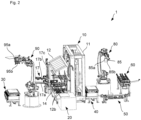
- Fig. 2
- zeigt eine perspektivische Ansicht der in
Fig. 1 dargestellten Fügeeinrichtung. - Fig. 3
- zeigt eine Fügepresse der in den
Figuren 1-2 dargestellten Fügeeinrichtung. - Gleiche Bezugszeichen, die in verschiedenen Figuren aufgeführt sind, benennen identische, einander entsprechende, oder funktionell ähnliche Elemente.
- Eine Fügeeinrichtung 1 zur Fertigung eines mehrere Bauelemente umfassenden Produkts (in diesem Beispiel eines Möbelstücks/Möbelkorpus) weist eine Fügepresse 10 auf, die eingerichtet ist, mehrere zur Verfügung gestellte Bauelemente zu fügen und zu verpressen. Die Bauelemente sind dabei mit Verbindungselementen ausgestattet, insbesondere mit Stiften, Holzdübeln, Flachdübeln, Vorsprüngen oder Ähnlichem, die in entsprechende Aussparungen eines benachbarten Bauelements eindringen können. Ein Verpressen der Bauelemente kann unter Einsatz eines Haftmittels erfolgen, um eine dauerhafte Verbindung herbeizuführen.
- Die Fügeeinrichtung 1 umfasst eine erste Zuführeinrichtung 20, eine zweite Zuführeinrichtung 30, eine dritte Zuführeinrichtung 40, eine vierte Zuführeinrichtung 50, eine fünfte Zuführeinrichtung 60 sowie eine Abtransporteinrichtung 70. Die Zuführeinrichtungen sind jeweils eingerichtet, Bauelemente zuzuführen, sodass die jeweiligen Bauelemente der Fügepresse 10 übergeben und durch die Fügepresse gefügt und verpresst werden können. Mittels der Abtransporteinrichtung 70 wird die gefügte Baugruppe von der Fügepresse 10 abtransportiert.
- Die erste Zuführeinrichtung 20, die zum Bereitstellen von Seitenelementen eines Möbelstücks eingerichtet ist, ist derart angeordnet, dass die Bauelemente ohne Richtungsänderung in die Fügepresse 10 gefördert werden können. Die erste Zuführeinrichtung 20 umfasst zum vereinzelten Bereitstellen der Seitenelemente einen Rollenförderer 21, der die Seitenelemente in einer Förderrichtung R1 bewegt.
- Die zweite Zuführeinrichtung 30 ist an einer ersten Seite der Fügepresse 10 und beabstandet zu dieser angeordnet. Die zweite Zuführeinrichtung 30 weist einen Rollenförderer 31 auf, der derart angeordnet ist, dass die durch den Rollenförderer 31 bewegten Bauelemente, die im Ausführungsbeispiel Rückwände der zu fertigenden Möbelstücke sind, wie nachfolgend näher erläutert der Fügepresse 10 übergeben werden können.
- Die zweite Zuführeinrichtung 30 stellt mit dem Rollenförderer 31 eine Förderbewegung in einer Richtung bereit, die parallel zu derjenigen der ersten Zuführeinrichtung 20 ausgerichtet ist. Allerdings ist die zweite Zuführeinrichtung 30 derart beabstandet zur ersten Zuführeinrichtung 20 sowie zur Fügepresse 10 angeordnet, dass zwischen der zweiten Zuführeinrichtung 30 einerseits und der ersten Zuführeinrichtung 20 und der Fügepresse 10 andererseits ein Freiraum vorliegt.
- Die Fügeeinrichtung 1 umfasst ferner die dritte Zuführeinrichtung 40, die, ähnlich wie die erste Zuführeinrichtung 20 und die zweite Zuführeinrichtung 30, einen Rollenförderer 41 zum Bewegen und Bereitstellen von einzelnen Bauelementen aufweist. Im Ausführungsbeispiel sind die durch die dritte Zuführeinrichtung 40 bereitgestellten Bauelemente Böden der zu fertigenden Möbelstücke. Die durch den Rollenförderer 41 vorgegebene Bewegungsrichtung ist parallel zu derjenigen der ersten Zuführeinrichtung 20.
- Die dritte Zuführeinrichtung 40 ist, zumindest abschnittweise, an einer zweiten Seite der Fügepresse 10 angeordnet, wobei die zweite Seite in eine entgegengesetzte Richtung weist, als die erste Seite der Fügepresse 10. Somit erstreckt sich die dritte Zuführeinrichtung 40 abschnittsweise parallel zur ersten Zuführeinrichtung 20 sowie abschnittsweise benachbart zur Fügepresse 10.
- Zum Bereitstellen von weiteren Bauelementen, insbesondere Traverleisten, umfasst die Fügeeinrichtung 1 die vierte Zuführeinrichtung 50, die benachbart zur dritten Zuführeinrichtung 40 an der von der Fügepresse 10 wegweisenden Seite angeordnet ist.
- Zum Bereitstellen von weiteren Bauelementen, insbesondere Mittelpfosten für die zu fertigenden Möbelstücke, ist in der Ausführungsform ferner die fünfte Zuführeinrichtung 60 vorgesehen, die diese Bauelemente in einer zu den Förderrichtungen der ersten bis vierten Zuführeinrichtung entgegengesetzten Richtung bereitstellt. Die fünfte Zuführeinrichtung 60 umfasst hierzu einen Riemenförderer 61.
- In dem Bereich zwischen der fünften Zuführeinrichtung 60 und der Fügepresse 10 ist eine erste Handhabungseinrichtung 80 angeordnet, die eingerichtet ist, zumindest ein Bauelement von der dritten Zuführeinrichtung 40, der vierten Zuführeinrichtung 50, oder der fünften Zuführeinrichtung 60 zu übernehmen und in den Bereich der Fügepresse 10 zu bewegen und das Bauelement zu übergeben. Die erste Handhabungseinrichtung 80 ist dabei als Mehrachsroboter ausgebildet, der mit einer Greifeinrichtung 85 zum Aufnehmen und Übergeben eines entsprechenden Bauelements vorgesehen ist.
- Die Greifeinrichtung 85 ist als Multifunktionsgreifer ausgebildet und umfasst Saugabschnitte 85a, um ein plattenförmiges Bauelement, wie beispielsweise eine Traverleiste, von der vierten Zuführeinrichtung 50 aufzunehmen. Ferner umfasst die Greifeinrichtung 85 eine Klemmeinrichtung 85b, um ein plattenförmiges Bauelement, wie beispielsweise einen Boden, von der dritten Zuführeinrichtung 40 aufzunehmen.
- In einem Bereich zwischen der zweiten Zuführeinrichtung 30 und der Fügepresse 10 ist eine zweite Handhabungseinrichtung 90 angeordnet, die eingerichtet ist, ein Bauelement von der zweiten Zuführeinrichtung 30 aufzunehmen und im Bereich der Fügepresse 10 zu übergeben. Die zweite Handhabungseinrichtung 90 ist als Mehrachsroboter ausgebildet, der eine zweite Greifeinrichtung 95 aufweist.
- Die zweite Handhabungseinrichtung 90 ist insbesondere eingerichtet, ein Bauelement (insbesondere ein Seitenteil) von der ersten Zuführeinrichtung 20 zu übernehmen und an einen bewegbaren Oberdruck 12 der Fügepresse 10 zu übergeben, und die zweite Handhabungseinrichtung 90 ist eingerichtet, ein weiteres Bauelement (insbesondere eine Rückwand) von der zweiten Zuführeinrichtung 30 zu übernehmen und an eine Schwenkvorrichtung 17 der Fügepresse 10 zu übergeben.
- Der Oberdruck 12 weist hierzu eine Aufnahmeeinrichtung 12a auf, die entlang von Schienen 12b des Oberdrucks in einen Bearbeitungsbereich bewegbar ist. In
Figuren 2-3 wurde die Aufnahmeeinrichtung 12a bereits in den Bearbeitungsbereich verfahren. Zur Übernahme eines Bauelements von der zweiten Handhabungseinrichtung 90 wird die Aufnahmeeinrichtung 12a zu den auskragenden Abschnitten der Schienen 12b bewegt. - Die Greifeinrichtung 95 ist hierfür als Multifunktionsgreifer ausgebildet und umfasst einen Greifer 95a, um ein plattenförmiges Bauelement, insbesondere eine von der ersten Zuführeinrichtung 20 bereitgestellte Seitenwand, aufzunehmen und an den Oberdruck 12 zu übergeben. Eine weitere mit der ersten Zuführeinrichtung 20 bereitgestellte Seitenwand kann mittels der ersten Zuführeinrichtung 20 weiter zur Fügepresse 10 bewegt werden. Ferner umfasst die Greifeinrichtung 95 Saugspanner 95b, um ein plattenförmiges Bauelement, insbesondere eine Rückwand, von der zweiten Zuführeinrichtung 30 aufzunehmen und an die Schwenkvorrichtung 17 der Fügepresse 10 zu übergeben.
- Zum Abtransport der mit der Fügepresse 10 gefertigten Möbelkonstruktionen ist die Abtransporteinrichtung 70 an einer zur ersten Zuführeinrichtung 20 entgegengesetzten Seite der Fügepresse 10 angeordnet. Die Abtransporteinrichtung 70 weist einen Bandförderer 71 auf, mit dem die gefügten Möbelstücke von der Fügepresse 10 weg bewegt werden können.
- Nachfolgend wird die Fügepresse 10 der Fügeeinrichtung 1 beschrieben.
- Die Fügepresse 10 umfasst einen Maschinenständer 11, an dem der in vertikaler Richtung bewegbare Oberdruck 12 angebracht ist. Der Oberdruck 12 umfasst eine Aufnahmeeinrichtung zum Aufnehmen eines Bauelements (insbesondere Seitenwand), wobei die Aufnahmeeinrichtung entlang des Oberdrucks 12 bewegbar ist.
- Ferner umfasst die Fügepresse 10 eine Fördereinrichtung 13, die als Riemenförderer ausgebildet ist, um ein oder mehrere Bauelemente, die von der ersten Zuführeinrichtung 20 bereitgestellt werden, in einen Bearbeitungsbereich der Fügepresse 10 zu bewegen. Im Bearbeitungsbereich der Fügepresse 10 ist ein Tisch 14 angeordnet, der beim Verpressen einer Baugruppe das mit der Fördereinrichtung 13 zugeführte Bauelement B2 (Seitenelement) hält oder abstützt.
- Zwischen Oberdruck 12 und dem Tisch 14 sind eine erste Halteeinrichtung 15 sowie eine zweite Halteeinrichtung 16 vorgesehen, die eingerichtet sind, stehende Werkstücke zu halten, bevor und während die Baugruppe verpresst wird.
- Die erste Halteeinrichtung 15 weist hierzu einen ersten Haltearm 15a und einen zweiten Haltearm 15b auf, die mit Saugeinrichtungen ausgestattet sind und ein Bauelement B1 (hier ein Boden) stehend halten. Die Haltearme 15a, 15b sind an einem ersten Halter 15c angebracht und entlang des Halters 15b in vertikaler Richtung bewegbar. Somit kann die erste Halteeinrichtung 15 durch Änderung des Abstands der Haltearme 15a an die Größe des zu haltenden Bauelements (hier: Bauelement B1) angepasst werden. Ferner ist die erste Halteeinrichtung 15 in und entgegen der Förderrichtung R1 entlang des Maschinenständers 11 verfahrbar.
- Die zweite Halteeinrichtung 16 ist, in der Förderrichtung R1, beabstandet zur ersten Halteeinrichtung 15 vorgesehen. Die zweite Halteeinrichtung 16 umfasst Haltearme 16a, 16b, die an einem zweiten Halter 16c angebracht und entlang des zweiten Halters 16c in vertikaler Richtung bewegbar sind, um Bauelemente B3 (Traverleisten) zwischen den Haltearmen 16a, 16b einzuklemmen und somit stehend zu halten. Der zweite Halter 16c ist in und entgegen der Förderrichtung R1 entlang des Maschinenständers 11 verfahrbar.
- Auf Grund der Bewegbarkeit der ersten Halteeinrichtung 15 und der zweiten Halteeinrichtung 16 kann ein Abstand zwischen der ersten Halteeinrichtung 15 und der zweiten Halteeinrichtung 16 variiert werden.
- Obwohl gemäß der Ausführungsform eine Bewegbarkeit der ersten Halteeinrichtung 15 und der zweiten Halteeinrichtung 16 in und entgegen der Förderrichtung R1 entlang des Maschinenständers 11 beschrieben wurde, kann es gemäß einer Modifikation auch vorgesehen sein, dass einer der Halteeinrichtungen 15, 16 relativ zum Maschinenständer 11 bewegbar und die jeweils andere Halteeinrichtung 15, 16 stationär am Maschinenständer 11 angebracht sein kann.
- Ferner umfasst die Fügepresse 10 die Schwenkvorrichtung 17, die eingerichtet ist, ein Bauelement (hier: Rückwand) aufzunehmen und in einer Schwenkbewegung in einen Bereich oberhalb des Tisches 14 und damit oberhalb eines am Tisch 14 bereitgestellten Bauelements zuzuführen.
- Die Schwenkvorrichtung umfasst einen ersten Aufnahmearm 17a, einen zweiten Aufnahmearm 17b sowie ein Gelenk 17c, an dem der erste Aufnahmearm 17a und der zweite Aufnahmearm 17b angebracht sind. Der erste Aufnahmearm 17a und der zweite Aufnahmearm 17b können jeweils unabhängig voneinander entlang des Gelenks 17c bewegt und somit variabel zueinander beabstandet werden. Somit ist es möglich, unterschiedlich große Bauelemente aufzunehmen.
- Nachfolgend soll ein beispielhafter Verfahrensablauf zum Fügen einer Baugruppe beschrieben werden. Hierzu wird zunächst mittels der dritten Zuführeinrichtung 40 zugeführt, sodass dieses Bauelement mit der Greifeinrichtung 85 der ersten Handhabungseinrichtung gegriffen werden kann. Die erste Handhabungseinrichtung bewegt das Bauelement in den Bereich der Fügepresse und übergibt das Bauelement der zweiten Halteeinrichtung 16.
- Daraufhin wird von der ersten Handhabungseinrichtung 80 in ähnlicher Weise ein weiteres Bauelement von der dritten Zuführeinrichtung 40 übernommen und der ersten Halteeinrichtung 15 übergeben. Somit sind die der Fügepresse 10 zugeführten Bauelemente stehend ausgerichtet.
- Parallel zu einem der bereits beschriebenen Verfahrensschritte oder nachfolgend zu einem oder mehreren dieser Verfahrensschritte wird mittels der ersten Zuführeinrichtung 20 ein Bauelement in der Förderrichtung R1 in die Fügepresse 10 zugeführt und so angeordnet, dass die erste und zweite Halteeinrichtung 15, 16 die jeweiligen Bauelemente oberhalb dieses horizontal ausgerichteten Bauelements anordnen oder durch eine weitere Bewegung der ersten oder zweiten Halteeinrichtung 15, 16, angeordnet werden.
- Ferner wird, parallel zu einem der bereits beschriebenen Verfahrensschritte oder nachfolgend zu einem oder mehreren dieser Verfahrensschritte, mit der zweiten Handhabungseinrichtung 90 ein Bauelement von der ersten Zuführeinrichtung 20 übernommen, indem dieses Bauelement (insbesondere Seitenwand) durch die Greifeinrichtung 95 gegriffen wird. Die zweite Handhabungseinrichtung 90 übergibt das Bauelement der Aufnahmeeinrichtung 12a des Oberdrucks 12 der Fügepresse 10. Nachfolgend wird die Aufnahmeeinrichtung 12a des Oberdrucks 12 in der Förderrichtung R1 in den Bearbeitungsbereich der Fügepresse 10 bewegt.
- Ferner übernimmt die zweite Handhabungseinrichtung 90 ein weiteres Bauelement (insbesondere Rückwand) von der zweiten Zuführeinrichtung 30 und übergibt dieses der Schwenkvorrichtung 17, die, nachdem die zweite Handhabungseinrichtung 90 das Bauelement an die Schwenkvorrichtung 17 übergeben hat, das Bauelement in den Bearbeitungsbereich der Fügepresse 10 durch eine Drehbewegung zustellt.
- Parallel oder zusätzlich kann bei Bedarf von der ersten Handhabungsvorrichtung 80 ein weiteres Bauelement übernommen und in einen Bereich zwischen der ersten Halteeinrichtung 15 und der zweiten Halteeinrichtung 16 gehalten werden. Daraufhin wird der Oberdruck in einer vertikalen Richtung nach unten bewegt und somit die Bauelemente zu einer Baugruppe verpresst. Diese Baugruppe kann nachfolgend in Richtung der Abtransporteinrichtung 70 bewegt und entsprechend von der Fügepresse entfernt werden.
- Auch wenn im Rahmen der Ausführungsform beschrieben wird, dass die Fügeeinrichtung zum Fügen eines Möbelstücks oder Möbelkorpus, beispielsweise eines Küchenelement-Korpus, eingesetzt wird, kann die Fügeeinrichtung auch zum Fügen anderer Baugruppen verwendet werden.
- Es ist ersichtlich, dass einzelne, jeweils in verschiedenen Ausführungsformen beschriebene Merkmale auch in einer einzigen Ausführungsform umgesetzt werden können, sofern sie nicht strukturell inkompatibel sind. Gleichermaßen können verschiedene Merkmale, die im Rahmen einer einzelnen Ausführungsform beschrieben sind, auch in mehreren Ausführungsformen einzeln oder in jeder geeigneten Unterkombination vorgesehen sein.
Claims (13)
- Fügeeinrichtung (1), umfassendeine Fügepresse (10), die eingerichtet ist, in einem Bearbeitungsbereich Bauelemente zu einer Baugruppe zu fügen, wobei die Fügepresse (10) eine erste Seite sowie eine zweite Seite aufweist, wobei die erste Seite und die zweite Seite entgegengesetzte Seiten der Fügepresse (10) sind,eine erste Handhabungseinrichtung (80), die eingerichtet ist, zumindest ein Bauelement zur ersten Seite der Fügepresse (10) zu bewegen, undeine zweite Handhabungseinrichtung (90), die eingerichtet ist, zumindest ein weiteres Bauelement zur zweiten Seite der Fügepresse (10) zum Bearbeitungsbereich der Fügepresse (10) zu bewegen,wobei die erste Handhabungseinrichtung (80) und/oder die zweite Handhabungseinrichtung (90) eingerichtet ist/sind, ein Bauelement während eines Fügevorgangs der Fügepresse (10) zu halten, gekennzeichnet, dadurch dassdie erste Handhabungseinrichtung (80) und die zweite Handhabungseinrichtung (90) als Mehrachsroboter ausgebildet sind.
- Fügeeinrichtung (1) gemäß Anspruch 1, wobei die zweite Handhabungseinrichtung (90) eingerichtet ist, ein erstes Bauelement an eine zum Bearbeitungsbereich bewegbare Aufnahmeeinrichtung (12a) eines Oberdrucks (12) der Fügepresse (10) und ein zweites Bauelement an eine benachbart zum Bearbeitungsbereich angeordnete Zustellvorrichtung, insbesondere eine Schwenkvorrichtung (17), der Fügepresse (10) zu übergeben.
- Fügeeinrichtung (1) gemäß einem der vorangegangenen Ansprüche, ferner umfassend eine erste Zuführeinrichtung (20), die derart angeordnet ist, ein Bauelement direkt in die Fügepresse (10) zu fördern.
- Fügeeinrichtung (1) gemäß einem der vorangegangenen Ansprüche, ferner umfassend eine zweite Zuführeinrichtung (30), die derart angeordnet ist, dass die zweite Handhabungseinrichtung (90) ein von der zweiten Zuführeinrichtung (30) bereitgestelltes Bauelement übernehmen und zur Fügepresse (10) bewegen kann.
- Fügeeinrichtung (1) gemäß einem der vorangegangenen Ansprüche, ferner umfassend eine dritte Zuführeinrichtung (40), die derart angeordnet ist, dass die erste Handhabungseinrichtung (80) ein von der dritten Zuführeinrichtung (40) bereitgestelltes Bauelement übernehmen und in den Bearbeitungsbereich der Fügepresse (10) bewegen kann,
wobei ferner bevorzugt ist, dass die Fügeeinrichtung (10) eine vierte Zuführeinrichtung (50) und/oder eine fünfte Zuführeinrichtung (60) umfasst, die derart angeordnet ist/sind, dass die erste Handhabungseinrichtung (80) ein von der vierten und/oder fünften Zuführeinrichtung (50, 60) bereitgestelltes Bauelement übernehmen und in den Bearbeitungsbereich der Fügepresse (10) bewegen kann. - Fügeeinrichtung (1) gemäß einem der vorangegangenen Ansprüche, wobei die erste Handhabungseinrichtung (80) und die zweite Handhabungseinrichtung (90) als 6-Achs-Roboter ausgebildet sind.
- Fügeeinrichtung (1) gemäß einem der vorangegangenen Ansprüche, wobei die erste Handhabungseinrichtung (80) und/oder die zweite Handhabungseinrichtung (90) mehrere Greifeinrichtungen aufweist/aufweisen,
insbesondere ausgewählt aus einem oder mehreren Saugabschnitten (85a), einer Klemmeinrichtung (85b), einem Greifer (95a) und einem Saugspanner (95b). - Fügeeinrichtung (1) gemäß einem der vorangegangenen Ansprüche, wobei die Fügepresse (10) eine Fördereinrichtung (13) mit einer Förderrichtung (R1) von einer dritten Seite zu einer vierten Seite der Fügepresse (10) aufweist.
- Fügeeinrichtung (1) gemäß einem der vorangegangenen Ansprüche, wobei die Fügepresse (10) eine Zustellvorrichtung, insbesondere eine Schwenkvorrichtung (17), zur Aufnahme eines von der zweiten Handhabungseinrichtung (90) bereitgestellten Bauelements aufweist, und/oder eine
erste Halteinrichtung (15) sowie eine zweite Halteeinrichtung (16) aufweist, die eingerichtet sind, ein stehendes Bauelement zu halten, bevor und während die Baugruppe verpresst wird. - Verfahren zum Fügen einer Baugruppe aus mehreren Bauelementen unter Einsatz einer Fügepresse (10), umfassend die Schritte:Zuführen eines Bauelements mittels einer ersten Handhabungseinrichtung (80) zu einer ersten Seite der Fügepresse (10), undZuführen eines weiteren Bauelements mittels einer zweiten Handhabungseinrichtung (90) zu einer zweiten Seite der Fügepresse (10) zu einem Bearbeitungsbereich der Fügepresse (10), wobei die erste Seite und die zweite Seite entgegengesetzte Seiten der Fügepresse (10) sind,wobei die erste Handhabungseinrichtung (80) und/oder die zweite Handhabungseinrichtung (90) ein Bauelement während eines Fügevorgangs der Fügepresse (10) halten, undwobei die erste Handhabungseinrichtung (80) und die zweite Handhabungseinrichtung (90) als Mehrachsroboter ausgebildet sind.
- Verfahren gemäß Anspruch 10, wobei die zweite Handhabungseinrichtung (90) ein erstes Bauelement an eine Aufnahmeeinrichtung eines Oberdrucks (12) der Fügepresse (10) und ein zweites Bauelement an eine Zustellvorrichtung, insbesondere eine Schwenkvorrichtung (17), der Fügepresse (10) übergibt.
- Verfahren gemäß Anspruch 10 oder 11, wobei der Fügepresse (10) mittels einer ersten Zuführeinrichtung (20) ein Bauelement von einer dritten Seite der Fügepresse (10) zugeführt wird.
- Verfahren gemäß einem der Ansprüche 10-12, wobei die in der Fügepresse (10) gefügte Baugruppe in einer Förderrichtung (R1) von einer dritten Seite zu einer vierten Seite der Fügepresse (10) bewegt wird.
Applications Claiming Priority (1)
| Application Number | Priority Date | Filing Date | Title |
|---|---|---|---|
| DE102021101750.5A DE102021101750A1 (de) | 2021-01-27 | 2021-01-27 | Fügeeinrichtung sowie Verfahren |
Publications (3)
| Publication Number | Publication Date |
|---|---|
| EP4046764A2 EP4046764A2 (de) | 2022-08-24 |
| EP4046764A3 EP4046764A3 (de) | 2022-11-02 |
| EP4046764B1 true EP4046764B1 (de) | 2024-08-14 |
Family
ID=80122059
Family Applications (1)
| Application Number | Title | Priority Date | Filing Date |
|---|---|---|---|
| EP22153171.8A Active EP4046764B1 (de) | 2021-01-27 | 2022-01-25 | Fügeeinrichtung sowie verfahren |
Country Status (3)
| Country | Link |
|---|---|
| EP (1) | EP4046764B1 (de) |
| DE (1) | DE102021101750A1 (de) |
| PL (1) | PL4046764T3 (de) |
Families Citing this family (1)
| Publication number | Priority date | Publication date | Assignee | Title |
|---|---|---|---|---|
| CN118003081B (zh) * | 2024-04-10 | 2024-06-07 | 德魁智能装备(苏州)有限公司 | 床芯自动化组装线 |
Citations (2)
| Publication number | Priority date | Publication date | Assignee | Title |
|---|---|---|---|---|
| DE19652756C1 (de) * | 1996-12-18 | 1998-10-22 | Huettenhoelscher Maschinenbau | Vorrichtung zum Zusammenfügen von Möbelkorpussen |
| DE102013001472B4 (de) * | 2013-01-29 | 2016-03-31 | Hüttenhölscher Maschinenbau GmbH & Co. KG | Verfahren und Anordnung zur Montage einer Möbelrückwand |
Family Cites Families (8)
| Publication number | Priority date | Publication date | Assignee | Title |
|---|---|---|---|---|
| DE19637178C2 (de) * | 1996-09-12 | 1998-08-06 | Fraunhofer Ges Forschung | Pressenvorrichtung zur Herstellung von Gestellmöbeln |
| DE19903458A1 (de) | 1999-01-28 | 2000-08-03 | Roland Fischer | Anordnung und Verfahren zur Montage von Möbelstücken |
| DE29924143U1 (de) * | 1999-04-19 | 2002-03-28 | Ligmatech Maschinenbau GmbH, 09638 Lichtenberg | Möbelkorpus-Montagelinie |
| DE502005003319D1 (de) | 2005-05-20 | 2008-04-30 | Ligmatech Automationssysteme | Möbelkorpus-Montagelinie |
| DE102006036193B4 (de) * | 2006-08-01 | 2008-04-24 | Prieß, Horstmann & Co Maschinenbau GmbH & Co KG | Vorrichtung und Verfahren zur Montage eines Möbelkorpus |
| DE202014101000U1 (de) | 2014-03-06 | 2015-06-12 | Kuka Systems Gmbh | Fügewerkzeug und Fügeeinrichtung |
| DE102014208519A1 (de) | 2014-05-07 | 2015-11-12 | Homag Holzbearbeitungssysteme Gmbh | Bearbeitungsvorrichtung und Bearbeitungsverfahren |
| DE102016007010B4 (de) | 2016-06-09 | 2024-08-01 | Hüttenhölscher Maschinenbau GmbH & Co. KG | Zuführeinrichtung für Möbelteile zu einer Zusammenfügeeinrichtung |
-
2021
- 2021-01-27 DE DE102021101750.5A patent/DE102021101750A1/de active Pending
-
2022
- 2022-01-25 EP EP22153171.8A patent/EP4046764B1/de active Active
- 2022-01-25 PL PL22153171.8T patent/PL4046764T3/pl unknown
Patent Citations (2)
| Publication number | Priority date | Publication date | Assignee | Title |
|---|---|---|---|---|
| DE19652756C1 (de) * | 1996-12-18 | 1998-10-22 | Huettenhoelscher Maschinenbau | Vorrichtung zum Zusammenfügen von Möbelkorpussen |
| DE102013001472B4 (de) * | 2013-01-29 | 2016-03-31 | Hüttenhölscher Maschinenbau GmbH & Co. KG | Verfahren und Anordnung zur Montage einer Möbelrückwand |
Also Published As
| Publication number | Publication date |
|---|---|
| EP4046764A3 (de) | 2022-11-02 |
| PL4046764T3 (pl) | 2024-11-25 |
| EP4046764A2 (de) | 2022-08-24 |
| DE102021101750A1 (de) | 2022-07-28 |
Similar Documents
| Publication | Publication Date | Title |
|---|---|---|
| EP3391987B1 (de) | Verfahren zum verschweissen von blechzuschnitten | |
| EP1601492B1 (de) | Fertigungsanlage für bauteile, insbesondere karosseriebauteile | |
| EP0977651B1 (de) | Verfahren und vorrichtung zum fertigen von komplexen werkstücken | |
| EP4041501B1 (de) | Verfahren zum transport und/oder handling von bauteilen | |
| EP3140076B1 (de) | Bearbeitungsvorrichtung und bearbeitungsverfahren | |
| AT514870B1 (de) | Anlage zur Bearbeitung von Platten oder Werkstücken aus Holz und Ähnlichem, Bearbeitungsmodul und entsprechende Bearbeitungsverfahren | |
| DE102015102818B4 (de) | Roboterhand mit Werkstückpositionierungsfunktion, Robotersystem und Verfahren zur Positionierung und Greifen eines Werkstücks | |
| DE102017121557B4 (de) | Verfahren und Vorrichtung zur Förderung und Positionierung von Werkstücken | |
| EP3140077B1 (de) | Werkzeugmaschinensystem und verfahren zum betreiben eines werkzeugmaschinensystems | |
| DE112016002792T5 (de) | Reckwalzmaschine und Reckwalzverfahren | |
| DE3622922C2 (de) | ||
| DE102015121884B4 (de) | Umform- und/oder Transferpresse mit zwei Stationsreihen und mit einer Transportvorrichtung zum Transport von Werkstücken entlang der aufeinanderfolgenden Bearbeitungstationen sowie Verfahren zum Fertigen von Produkten aus Werkstücken | |
| DE102020116123B4 (de) | Fertigungsstation für Werkstücke, insbesondere Karosserieteile, sowie Fertigungsanlage | |
| EP3744472B1 (de) | Einsetzteile-fügestation | |
| EP4046764A2 (de) | Fügeeinrichtung sowie verfahren | |
| EP3663035B1 (de) | Werkzeugmaschine mit werkzeugspindel und ladeportal | |
| DE102019107077B4 (de) | Förderanlage zum Umsetzen zumindest eines plattenförmigen Werkstücks | |
| AT522859B1 (de) | Übergabeverfahren, dafür ausgebildetes Manipulationssystem sowie Biegeanlage | |
| EP4166864B1 (de) | Verfahren und montagevorrichtung zur automatisierten montage eines rahmens für ein luftkanalelement | |
| EP4461676A1 (de) | Fördereinrichtung | |
| EP3548215B1 (de) | Verfahren zum bonden grosser module und entsprechende bondanordnung | |
| EP3421151A1 (de) | Verfahren zum bearbeiten von zuschnitten aus einem plattenförmigen material | |
| EP3624989A1 (de) | Beschickungsvorrichtung und beschickungsverfahren | |
| DE102020108037A1 (de) | Tooling zur Aufnahme von Werkstücken | |
| EP3951039B1 (de) | Nähmaschinenbeschickungsvorrichtung zum automatischen beschicken einer nähmaschine mit nähteilen |
Legal Events
| Date | Code | Title | Description |
|---|---|---|---|
| PUAI | Public reference made under article 153(3) epc to a published international application that has entered the european phase |
Free format text: ORIGINAL CODE: 0009012 |
|
| STAA | Information on the status of an ep patent application or granted ep patent |
Free format text: STATUS: THE APPLICATION HAS BEEN PUBLISHED |
|
| AK | Designated contracting states |
Kind code of ref document: A2 Designated state(s): AL AT BE BG CH CY CZ DE DK EE ES FI FR GB GR HR HU IE IS IT LI LT LU LV MC MK MT NL NO PL PT RO RS SE SI SK SM TR |
|
| PUAL | Search report despatched |
Free format text: ORIGINAL CODE: 0009013 |
|
| RIC1 | Information provided on ipc code assigned before grant |
Ipc: B27M 3/18 20060101AFI20220921BHEP |
|
| AK | Designated contracting states |
Kind code of ref document: A3 Designated state(s): AL AT BE BG CH CY CZ DE DK EE ES FI FR GB GR HR HU IE IS IT LI LT LU LV MC MK MT NL NO PL PT RO RS SE SI SK SM TR |
|
| RIC1 | Information provided on ipc code assigned before grant |
Ipc: B27M 3/18 20060101AFI20220926BHEP |
|
| STAA | Information on the status of an ep patent application or granted ep patent |
Free format text: STATUS: REQUEST FOR EXAMINATION WAS MADE |
|
| 17P | Request for examination filed |
Effective date: 20230329 |
|
| RBV | Designated contracting states (corrected) |
Designated state(s): AL AT BE BG CH CY CZ DE DK EE ES FI FR GB GR HR HU IE IS IT LI LT LU LV MC MK MT NL NO PL PT RO RS SE SI SK SM TR |
|
| P01 | Opt-out of the competence of the unified patent court (upc) registered |
Effective date: 20230529 |
|
| STAA | Information on the status of an ep patent application or granted ep patent |
Free format text: STATUS: EXAMINATION IS IN PROGRESS |
|
| 17Q | First examination report despatched |
Effective date: 20230818 |
|
| REG | Reference to a national code |
Ref country code: DE Ref legal event code: R079 Free format text: PREVIOUS MAIN CLASS: B27M0003180000 Ipc: B27M0001080000 Ref document number: 502022001423 Country of ref document: DE |
|
| GRAP | Despatch of communication of intention to grant a patent |
Free format text: ORIGINAL CODE: EPIDOSNIGR1 |
|
| STAA | Information on the status of an ep patent application or granted ep patent |
Free format text: STATUS: GRANT OF PATENT IS INTENDED |
|
| INTG | Intention to grant announced |
Effective date: 20240314 |
|
| RIC1 | Information provided on ipc code assigned before grant |
Ipc: F16B 12/04 20060101ALI20240301BHEP Ipc: B27M 3/00 20060101ALI20240301BHEP Ipc: B27M 3/18 20060101ALI20240301BHEP Ipc: B27M 1/08 20060101AFI20240301BHEP |
|
| GRAS | Grant fee paid |
Free format text: ORIGINAL CODE: EPIDOSNIGR3 |
|
| GRAA | (expected) grant |
Free format text: ORIGINAL CODE: 0009210 |
|
| STAA | Information on the status of an ep patent application or granted ep patent |
Free format text: STATUS: THE PATENT HAS BEEN GRANTED |
|
| AK | Designated contracting states |
Kind code of ref document: B1 Designated state(s): AL AT BE BG CH CY CZ DE DK EE ES FI FR GB GR HR HU IE IS IT LI LT LU LV MC MK MT NL NO PL PT RO RS SE SI SK SM TR |
|
| REG | Reference to a national code |
Ref country code: GB Ref legal event code: FG4D Free format text: NOT ENGLISH |
|
| REG | Reference to a national code |
Ref country code: CH Ref legal event code: EP |
|
| REG | Reference to a national code |
Ref country code: DE Ref legal event code: R096 Ref document number: 502022001423 Country of ref document: DE |
|
| REG | Reference to a national code |
Ref country code: IE Ref legal event code: FG4D Free format text: LANGUAGE OF EP DOCUMENT: GERMAN |
|
| REG | Reference to a national code |
Ref country code: LT Ref legal event code: MG9D |
|
| REG | Reference to a national code |
Ref country code: NL Ref legal event code: MP Effective date: 20240814 |
|
| PG25 | Lapsed in a contracting state [announced via postgrant information from national office to epo] |
Ref country code: NO Free format text: LAPSE BECAUSE OF FAILURE TO SUBMIT A TRANSLATION OF THE DESCRIPTION OR TO PAY THE FEE WITHIN THE PRESCRIBED TIME-LIMIT Effective date: 20241114 |
|
| PG25 | Lapsed in a contracting state [announced via postgrant information from national office to epo] |
Ref country code: NL Free format text: LAPSE BECAUSE OF FAILURE TO SUBMIT A TRANSLATION OF THE DESCRIPTION OR TO PAY THE FEE WITHIN THE PRESCRIBED TIME-LIMIT Effective date: 20240814 Ref country code: PT Free format text: LAPSE BECAUSE OF FAILURE TO SUBMIT A TRANSLATION OF THE DESCRIPTION OR TO PAY THE FEE WITHIN THE PRESCRIBED TIME-LIMIT Effective date: 20241216 Ref country code: GR Free format text: LAPSE BECAUSE OF FAILURE TO SUBMIT A TRANSLATION OF THE DESCRIPTION OR TO PAY THE FEE WITHIN THE PRESCRIBED TIME-LIMIT Effective date: 20241115 Ref country code: FI Free format text: LAPSE BECAUSE OF FAILURE TO SUBMIT A TRANSLATION OF THE DESCRIPTION OR TO PAY THE FEE WITHIN THE PRESCRIBED TIME-LIMIT Effective date: 20240814 |
|
| PG25 | Lapsed in a contracting state [announced via postgrant information from national office to epo] |
Ref country code: BG Free format text: LAPSE BECAUSE OF FAILURE TO SUBMIT A TRANSLATION OF THE DESCRIPTION OR TO PAY THE FEE WITHIN THE PRESCRIBED TIME-LIMIT Effective date: 20240814 |
|
| PG25 | Lapsed in a contracting state [announced via postgrant information from national office to epo] |
Ref country code: LV Free format text: LAPSE BECAUSE OF FAILURE TO SUBMIT A TRANSLATION OF THE DESCRIPTION OR TO PAY THE FEE WITHIN THE PRESCRIBED TIME-LIMIT Effective date: 20240814 |
|
| PG25 | Lapsed in a contracting state [announced via postgrant information from national office to epo] |
Ref country code: IS Free format text: LAPSE BECAUSE OF FAILURE TO SUBMIT A TRANSLATION OF THE DESCRIPTION OR TO PAY THE FEE WITHIN THE PRESCRIBED TIME-LIMIT Effective date: 20241214 |
|
| PG25 | Lapsed in a contracting state [announced via postgrant information from national office to epo] |
Ref country code: HR Free format text: LAPSE BECAUSE OF FAILURE TO SUBMIT A TRANSLATION OF THE DESCRIPTION OR TO PAY THE FEE WITHIN THE PRESCRIBED TIME-LIMIT Effective date: 20240814 |
|
| PG25 | Lapsed in a contracting state [announced via postgrant information from national office to epo] |
Ref country code: RS Free format text: LAPSE BECAUSE OF FAILURE TO SUBMIT A TRANSLATION OF THE DESCRIPTION OR TO PAY THE FEE WITHIN THE PRESCRIBED TIME-LIMIT Effective date: 20241114 Ref country code: ES Free format text: LAPSE BECAUSE OF FAILURE TO SUBMIT A TRANSLATION OF THE DESCRIPTION OR TO PAY THE FEE WITHIN THE PRESCRIBED TIME-LIMIT Effective date: 20240814 |
|
| PG25 | Lapsed in a contracting state [announced via postgrant information from national office to epo] |
Ref country code: RS Free format text: LAPSE BECAUSE OF FAILURE TO SUBMIT A TRANSLATION OF THE DESCRIPTION OR TO PAY THE FEE WITHIN THE PRESCRIBED TIME-LIMIT Effective date: 20241114 Ref country code: PT Free format text: LAPSE BECAUSE OF FAILURE TO SUBMIT A TRANSLATION OF THE DESCRIPTION OR TO PAY THE FEE WITHIN THE PRESCRIBED TIME-LIMIT Effective date: 20241216 Ref country code: NO Free format text: LAPSE BECAUSE OF FAILURE TO SUBMIT A TRANSLATION OF THE DESCRIPTION OR TO PAY THE FEE WITHIN THE PRESCRIBED TIME-LIMIT Effective date: 20241114 Ref country code: NL Free format text: LAPSE BECAUSE OF FAILURE TO SUBMIT A TRANSLATION OF THE DESCRIPTION OR TO PAY THE FEE WITHIN THE PRESCRIBED TIME-LIMIT Effective date: 20240814 Ref country code: LV Free format text: LAPSE BECAUSE OF FAILURE TO SUBMIT A TRANSLATION OF THE DESCRIPTION OR TO PAY THE FEE WITHIN THE PRESCRIBED TIME-LIMIT Effective date: 20240814 Ref country code: IS Free format text: LAPSE BECAUSE OF FAILURE TO SUBMIT A TRANSLATION OF THE DESCRIPTION OR TO PAY THE FEE WITHIN THE PRESCRIBED TIME-LIMIT Effective date: 20241214 Ref country code: HR Free format text: LAPSE BECAUSE OF FAILURE TO SUBMIT A TRANSLATION OF THE DESCRIPTION OR TO PAY THE FEE WITHIN THE PRESCRIBED TIME-LIMIT Effective date: 20240814 Ref country code: GR Free format text: LAPSE BECAUSE OF FAILURE TO SUBMIT A TRANSLATION OF THE DESCRIPTION OR TO PAY THE FEE WITHIN THE PRESCRIBED TIME-LIMIT Effective date: 20241115 Ref country code: FI Free format text: LAPSE BECAUSE OF FAILURE TO SUBMIT A TRANSLATION OF THE DESCRIPTION OR TO PAY THE FEE WITHIN THE PRESCRIBED TIME-LIMIT Effective date: 20240814 Ref country code: ES Free format text: LAPSE BECAUSE OF FAILURE TO SUBMIT A TRANSLATION OF THE DESCRIPTION OR TO PAY THE FEE WITHIN THE PRESCRIBED TIME-LIMIT Effective date: 20240814 Ref country code: BG Free format text: LAPSE BECAUSE OF FAILURE TO SUBMIT A TRANSLATION OF THE DESCRIPTION OR TO PAY THE FEE WITHIN THE PRESCRIBED TIME-LIMIT Effective date: 20240814 |
|
| PG25 | Lapsed in a contracting state [announced via postgrant information from national office to epo] |
Ref country code: DK Free format text: LAPSE BECAUSE OF FAILURE TO SUBMIT A TRANSLATION OF THE DESCRIPTION OR TO PAY THE FEE WITHIN THE PRESCRIBED TIME-LIMIT Effective date: 20240814 Ref country code: SM Free format text: LAPSE BECAUSE OF FAILURE TO SUBMIT A TRANSLATION OF THE DESCRIPTION OR TO PAY THE FEE WITHIN THE PRESCRIBED TIME-LIMIT Effective date: 20240814 Ref country code: RO Free format text: LAPSE BECAUSE OF FAILURE TO SUBMIT A TRANSLATION OF THE DESCRIPTION OR TO PAY THE FEE WITHIN THE PRESCRIBED TIME-LIMIT Effective date: 20240814 |
|
| PG25 | Lapsed in a contracting state [announced via postgrant information from national office to epo] |
Ref country code: EE Free format text: LAPSE BECAUSE OF FAILURE TO SUBMIT A TRANSLATION OF THE DESCRIPTION OR TO PAY THE FEE WITHIN THE PRESCRIBED TIME-LIMIT Effective date: 20240814 |
|
| PG25 | Lapsed in a contracting state [announced via postgrant information from national office to epo] |
Ref country code: CZ Free format text: LAPSE BECAUSE OF FAILURE TO SUBMIT A TRANSLATION OF THE DESCRIPTION OR TO PAY THE FEE WITHIN THE PRESCRIBED TIME-LIMIT Effective date: 20240814 |
|
| PG25 | Lapsed in a contracting state [announced via postgrant information from national office to epo] |
Ref country code: SK Free format text: LAPSE BECAUSE OF FAILURE TO SUBMIT A TRANSLATION OF THE DESCRIPTION OR TO PAY THE FEE WITHIN THE PRESCRIBED TIME-LIMIT Effective date: 20240814 |
|
| REG | Reference to a national code |
Ref country code: DE Ref legal event code: R097 Ref document number: 502022001423 Country of ref document: DE |
|
| PLBE | No opposition filed within time limit |
Free format text: ORIGINAL CODE: 0009261 |
|
| STAA | Information on the status of an ep patent application or granted ep patent |
Free format text: STATUS: NO OPPOSITION FILED WITHIN TIME LIMIT |
|
| 26N | No opposition filed |
Effective date: 20250515 |
|
| REG | Reference to a national code |
Ref country code: CH Ref legal event code: PL |
|
| PG25 | Lapsed in a contracting state [announced via postgrant information from national office to epo] |
Ref country code: SE Free format text: LAPSE BECAUSE OF FAILURE TO SUBMIT A TRANSLATION OF THE DESCRIPTION OR TO PAY THE FEE WITHIN THE PRESCRIBED TIME-LIMIT Effective date: 20240814 |
|
| PG25 | Lapsed in a contracting state [announced via postgrant information from national office to epo] |
Ref country code: LU Free format text: LAPSE BECAUSE OF NON-PAYMENT OF DUE FEES Effective date: 20250125 Ref country code: MC Free format text: LAPSE BECAUSE OF FAILURE TO SUBMIT A TRANSLATION OF THE DESCRIPTION OR TO PAY THE FEE WITHIN THE PRESCRIBED TIME-LIMIT Effective date: 20240814 |
|
| PG25 | Lapsed in a contracting state [announced via postgrant information from national office to epo] |
Ref country code: BE Free format text: LAPSE BECAUSE OF NON-PAYMENT OF DUE FEES Effective date: 20250131 |
|
| PG25 | Lapsed in a contracting state [announced via postgrant information from national office to epo] |
Ref country code: CH Free format text: LAPSE BECAUSE OF NON-PAYMENT OF DUE FEES Effective date: 20250131 |
|
| REG | Reference to a national code |
Ref country code: BE Ref legal event code: MM Effective date: 20250131 |
|
| PG25 | Lapsed in a contracting state [announced via postgrant information from national office to epo] |
Ref country code: IE Free format text: LAPSE BECAUSE OF NON-PAYMENT OF DUE FEES Effective date: 20250125 |
|
| PGFP | Annual fee paid to national office [announced via postgrant information from national office to epo] |
Ref country code: PL Payment date: 20251216 Year of fee payment: 5 |
|
| PGFP | Annual fee paid to national office [announced via postgrant information from national office to epo] |
Ref country code: DE Payment date: 20260122 Year of fee payment: 5 |
|
| PGFP | Annual fee paid to national office [announced via postgrant information from national office to epo] |
Ref country code: AT Payment date: 20260301 Year of fee payment: 5 |
|
| PGFP | Annual fee paid to national office [announced via postgrant information from national office to epo] |
Ref country code: IT Payment date: 20260130 Year of fee payment: 5 |
|
| PGFP | Annual fee paid to national office [announced via postgrant information from national office to epo] |
Ref country code: FR Payment date: 20260122 Year of fee payment: 5 |