EP4046933B1 - Capuchon de contenant et son procédé de production - Google Patents
Capuchon de contenant et son procédé de production Download PDFInfo
- Publication number
- EP4046933B1 EP4046933B1 EP22164282.0A EP22164282A EP4046933B1 EP 4046933 B1 EP4046933 B1 EP 4046933B1 EP 22164282 A EP22164282 A EP 22164282A EP 4046933 B1 EP4046933 B1 EP 4046933B1
- Authority
- EP
- European Patent Office
- Prior art keywords
- tab
- lateral
- axis
- stretch
- line
- Prior art date
- Legal status (The legal status is an assumption and is not a legal conclusion. Google has not performed a legal analysis and makes no representation as to the accuracy of the status listed.)
- Active
Links
Images







Classifications
-
- B—PERFORMING OPERATIONS; TRANSPORTING
- B65—CONVEYING; PACKING; STORING; HANDLING THIN OR FILAMENTARY MATERIAL
- B65D—CONTAINERS FOR STORAGE OR TRANSPORT OF ARTICLES OR MATERIALS, e.g. BAGS, BARRELS, BOTTLES, BOXES, CANS, CARTONS, CRATES, DRUMS, JARS, TANKS, HOPPERS, FORWARDING CONTAINERS; ACCESSORIES, CLOSURES, OR FITTINGS THEREFOR; PACKAGING ELEMENTS; PACKAGES
- B65D55/00—Accessories for container closures not otherwise provided for
- B65D55/02—Locking devices; Means for discouraging or indicating unauthorised opening or removal of closure
- B65D55/06—Deformable or tearable wires, strings or strips; Use of seals
- B65D55/08—Annular elements encircling container necks
- B65D55/0818—Destructible or permanently removable bands, e.g. adhesive
-
- B—PERFORMING OPERATIONS; TRANSPORTING
- B65—CONVEYING; PACKING; STORING; HANDLING THIN OR FILAMENTARY MATERIAL
- B65D—CONTAINERS FOR STORAGE OR TRANSPORT OF ARTICLES OR MATERIALS, e.g. BAGS, BARRELS, BOTTLES, BOXES, CANS, CARTONS, CRATES, DRUMS, JARS, TANKS, HOPPERS, FORWARDING CONTAINERS; ACCESSORIES, CLOSURES, OR FITTINGS THEREFOR; PACKAGING ELEMENTS; PACKAGES
- B65D55/00—Accessories for container closures not otherwise provided for
- B65D55/16—Devices preventing loss of removable closure members
-
- B—PERFORMING OPERATIONS; TRANSPORTING
- B65—CONVEYING; PACKING; STORING; HANDLING THIN OR FILAMENTARY MATERIAL
- B65D—CONTAINERS FOR STORAGE OR TRANSPORT OF ARTICLES OR MATERIALS, e.g. BAGS, BARRELS, BOTTLES, BOXES, CANS, CARTONS, CRATES, DRUMS, JARS, TANKS, HOPPERS, FORWARDING CONTAINERS; ACCESSORIES, CLOSURES, OR FITTINGS THEREFOR; PACKAGING ELEMENTS; PACKAGES
- B65D41/00—Caps, e.g. crown caps or crown seals, i.e. members having parts arranged for engagement with the external periphery of a neck or wall defining a pouring opening or discharge aperture; Protective cap-like covers for closure members, e.g. decorative covers of metal foil or paper
- B65D41/32—Caps or cap-like covers with lines of weakness, tearing-strips, tags, or like opening or removal devices, e.g. to facilitate formation of pouring openings
- B65D41/34—Threaded or like caps or cap-like covers provided with tamper elements formed in, or attached to, the closure skirt
-
- B—PERFORMING OPERATIONS; TRANSPORTING
- B26—HAND CUTTING TOOLS; CUTTING; SEVERING
- B26D—CUTTING; DETAILS COMMON TO MACHINES FOR PERFORATING, PUNCHING, CUTTING-OUT, STAMPING-OUT OR SEVERING
- B26D1/00—Cutting through work characterised by the nature or movement of the cutting member or particular materials not otherwise provided for; Apparatus or machines therefor; Cutting members therefor
- B26D1/0006—Cutting members therefor
-
- B—PERFORMING OPERATIONS; TRANSPORTING
- B26—HAND CUTTING TOOLS; CUTTING; SEVERING
- B26D—CUTTING; DETAILS COMMON TO MACHINES FOR PERFORATING, PUNCHING, CUTTING-OUT, STAMPING-OUT OR SEVERING
- B26D7/00—Details of apparatus for cutting, cutting-out, stamping-out, punching, perforating, or severing by means other than cutting
- B26D7/06—Arrangements for feeding or delivering work of other than sheet, web, or filamentary form
-
- B—PERFORMING OPERATIONS; TRANSPORTING
- B26—HAND CUTTING TOOLS; CUTTING; SEVERING
- B26F—PERFORATING; PUNCHING; CUTTING-OUT; STAMPING-OUT; SEVERING BY MEANS OTHER THAN CUTTING
- B26F1/00—Perforating; Punching; Cutting-out; Stamping-out; Apparatus therefor
- B26F1/18—Perforating by slitting, i.e. forming cuts closed at their ends without removal of material
-
- B—PERFORMING OPERATIONS; TRANSPORTING
- B65—CONVEYING; PACKING; STORING; HANDLING THIN OR FILAMENTARY MATERIAL
- B65D—CONTAINERS FOR STORAGE OR TRANSPORT OF ARTICLES OR MATERIALS, e.g. BAGS, BARRELS, BOTTLES, BOXES, CANS, CARTONS, CRATES, DRUMS, JARS, TANKS, HOPPERS, FORWARDING CONTAINERS; ACCESSORIES, CLOSURES, OR FITTINGS THEREFOR; PACKAGING ELEMENTS; PACKAGES
- B65D41/00—Caps, e.g. crown caps or crown seals, i.e. members having parts arranged for engagement with the external periphery of a neck or wall defining a pouring opening or discharge aperture; Protective cap-like covers for closure members, e.g. decorative covers of metal foil or paper
- B65D41/32—Caps or cap-like covers with lines of weakness, tearing-strips, tags, or like opening or removal devices, e.g. to facilitate formation of pouring openings
- B65D41/34—Threaded or like caps or cap-like covers provided with tamper elements formed in, or attached to, the closure skirt
- B65D41/3423—Threaded or like caps or cap-like covers provided with tamper elements formed in, or attached to, the closure skirt with flexible tabs, or elements rotated from a non-engaging to an engaging position, formed on the tamper element or in the closure skirt
- B65D41/3428—Threaded or like caps or cap-like covers provided with tamper elements formed in, or attached to, the closure skirt with flexible tabs, or elements rotated from a non-engaging to an engaging position, formed on the tamper element or in the closure skirt the tamper element being integrally connected to the closure by means of bridges
-
- B—PERFORMING OPERATIONS; TRANSPORTING
- B26—HAND CUTTING TOOLS; CUTTING; SEVERING
- B26D—CUTTING; DETAILS COMMON TO MACHINES FOR PERFORATING, PUNCHING, CUTTING-OUT, STAMPING-OUT OR SEVERING
- B26D1/00—Cutting through work characterised by the nature or movement of the cutting member or particular materials not otherwise provided for; Apparatus or machines therefor; Cutting members therefor
- B26D1/0006—Cutting members therefor
- B26D2001/0033—Cutting members therefor assembled from multiple blades
-
- B—PERFORMING OPERATIONS; TRANSPORTING
- B26—HAND CUTTING TOOLS; CUTTING; SEVERING
- B26D—CUTTING; DETAILS COMMON TO MACHINES FOR PERFORATING, PUNCHING, CUTTING-OUT, STAMPING-OUT OR SEVERING
- B26D1/00—Cutting through work characterised by the nature or movement of the cutting member or particular materials not otherwise provided for; Apparatus or machines therefor; Cutting members therefor
- B26D1/0006—Cutting members therefor
- B26D2001/006—Cutting members therefor the cutting blade having a special shape, e.g. a special outline, serrations
-
- B—PERFORMING OPERATIONS; TRANSPORTING
- B26—HAND CUTTING TOOLS; CUTTING; SEVERING
- B26F—PERFORATING; PUNCHING; CUTTING-OUT; STAMPING-OUT; SEVERING BY MEANS OTHER THAN CUTTING
- B26F2210/00—Perforating, punching, cutting-out, stamping-out, severing by means other than cutting of specific products
- B26F2210/04—Making plastic pilferproof screw caps by cutting a tamper ring
-
- B—PERFORMING OPERATIONS; TRANSPORTING
- B29—WORKING OF PLASTICS; WORKING OF SUBSTANCES IN A PLASTIC STATE IN GENERAL
- B29C—SHAPING OR JOINING OF PLASTICS; SHAPING OF MATERIAL IN A PLASTIC STATE, NOT OTHERWISE PROVIDED FOR; AFTER-TREATMENT OF THE SHAPED PRODUCTS, e.g. REPAIRING
- B29C37/00—Component parts, details, accessories or auxiliary operations, not covered by group B29C33/00 or B29C35/00
- B29C37/0053—Moulding articles characterised by the shape of the surface, e.g. ribs, high polish
-
- B—PERFORMING OPERATIONS; TRANSPORTING
- B65—CONVEYING; PACKING; STORING; HANDLING THIN OR FILAMENTARY MATERIAL
- B65D—CONTAINERS FOR STORAGE OR TRANSPORT OF ARTICLES OR MATERIALS, e.g. BAGS, BARRELS, BOTTLES, BOXES, CANS, CARTONS, CRATES, DRUMS, JARS, TANKS, HOPPERS, FORWARDING CONTAINERS; ACCESSORIES, CLOSURES, OR FITTINGS THEREFOR; PACKAGING ELEMENTS; PACKAGES
- B65D2251/00—Details relating to container closures
- B65D2251/10—Details of hinged closures
- B65D2251/1008—Means for locking the closure in open position
-
- B—PERFORMING OPERATIONS; TRANSPORTING
- B65—CONVEYING; PACKING; STORING; HANDLING THIN OR FILAMENTARY MATERIAL
- B65D—CONTAINERS FOR STORAGE OR TRANSPORT OF ARTICLES OR MATERIALS, e.g. BAGS, BARRELS, BOTTLES, BOXES, CANS, CARTONS, CRATES, DRUMS, JARS, TANKS, HOPPERS, FORWARDING CONTAINERS; ACCESSORIES, CLOSURES, OR FITTINGS THEREFOR; PACKAGING ELEMENTS; PACKAGES
- B65D2401/00—Tamper-indicating means
- B65D2401/15—Tearable part of the closure
-
- B—PERFORMING OPERATIONS; TRANSPORTING
- B65—CONVEYING; PACKING; STORING; HANDLING THIN OR FILAMENTARY MATERIAL
- B65D—CONTAINERS FOR STORAGE OR TRANSPORT OF ARTICLES OR MATERIALS, e.g. BAGS, BARRELS, BOTTLES, BOXES, CANS, CARTONS, CRATES, DRUMS, JARS, TANKS, HOPPERS, FORWARDING CONTAINERS; ACCESSORIES, CLOSURES, OR FITTINGS THEREFOR; PACKAGING ELEMENTS; PACKAGES
- B65D2401/00—Tamper-indicating means
- B65D2401/15—Tearable part of the closure
- B65D2401/30—Tamper-ring remaining connected to closure after initial removal
Definitions
- This invention relates to a cap for a container, and a relative method for making the cap for the container.
- the invention relates to a cap provided with a retaining ring, which can be associated with a neck of the container, the cap being also provided with a closing element which, after opening, remains connected to the retaining ring and a combination of a cap and of a neck of the container, to which the cap is associated.
- the invention also relates to the method for making the cap for the container, in which the closing element remains connected to the retaining ring after opening.
- the cap is particularly, but not exclusively, suitable for bottles designed to contain liquid substances.
- prior art caps for bottles comprising a cup-shaped body provided with an inner thread designed to engage with an outer thread of a neck of the bottle.
- the prior art caps are also provided with a security ring connected to the cup-shaped body by means of a tear line provided with a plurality of breakable elements, for example breakable bridges.
- a tear line provided with a plurality of breakable elements, for example breakable bridges.
- caps have been proposed which are provided with a retaining ring, which can be associated with a neck of a bottle, and a closing element, connected to the retaining ring by means of a hinge.
- the closing element can be rotated about the hinge between an open condition, in which a user can access the contents of the bottle, and a closed condition, in which the closing element prevents access to the bottle.
- the hinge keeps the closing element associated with the retaining ring and, therefore, the bottle, preventing the closing element from being thrown on the ground independently of the bottle.
- caps with the hinge of known type may have zones with a very reduced thickness, which are difficult to obtain because the molten polymeric material flows with difficulty in the portions of the mould intended to form these zones.
- US6474491 discloses an example of a cap with zones of very reduced thickness.
- US 6474491 discloses a cap according to the preamble of claim 1.
- WO2019031779 discloses another example of a cap rather complicated to manufacture.
- An aim of the invention is to improve the caps of known type, particularly the caps comprising a retaining ring designed to remain associated with a neck of the container and a closing element removably engageable with the neck to allow a user to open or alternatively close the container.
- a further aim is to provide a cap for a container, provided with a closing element which remains connected to the retaining ring, which in addition can remain stably locked in a position after opening.
- Another aim of the invention is to improve the production method of the caps of known type, particularly the caps comprising a retaining ring designed to remain associated with a neck of the container and a closing element removably engageable with the neck to allow a user to open or alternatively close the container.
- cap and neck of known type particularly wherein the caps comprising a retaining ring designed to remain associated with a neck of the container and a closing element removably engageable with the neck to allow a user to open or alternatively close the container is described but does not form part of the invention.
- a closing cap for a container comprising a lateral wall extending about an axis and a transversal edge positioned at one end of the lateral wall, a separation line being provided on the lateral wall to define: a retaining ring, which is configured to remain anchored to the neck; a closing element removably engageable with the neck, in such a way as to open or close the container; wherein the separation line extends about an axis, the circumferential separation line being interrupted to leave the retaining ring and the closing element joined, and wherein the retaining ring comprises: a retaining portion, which is configured to internally engage with a locking ring of the neck and it extends up to a free edge of the retaining ring; a joining portion at which the retaining ring is joined to the closing element; a first connecting band, which extends from a first end zone of the joining portion to the retaining portion, and a second connecting band, which extends from a second end zone of the joining
- a closing cap for a container comprising a lateral wall extending about an axis and a transversal wall positioned at one end of the lateral wall, a separation line being provided on the lateral wall to define a retaining ring, which is configured to remain anchored to a neck of the container and extends to a free edge; a closing element removably engageable with the neck, so as to open or close the container; the separation line extending around the axis and being circumferentially interrupted to leave the retaining ring and the closing element joined; wherein the retaining ring comprises: a joining portion at which the retaining ring is joined to the closing element; a first connecting band, which extends from a first end zone of the joining portion, and a second connecting band, which extends from a second end zone of the joining portion, the second end zone being positioned circumferentially on the opposite side to the first end zone; a tab, interposed between the first connecting band and the second connecting
- a closing cap for a container and a neck of the container on which the cap is applied, wherein the cap comprises a lateral wall extending about an axis and a transversal wall positioned at one end of the lateral wall, a separation line being provided on the lateral wall to define: a retaining ring, which is configured to remain anchored to the neck; a closing element removably engageable with the neck, in such a way as to open or close the container; the separation line extending about the axis and being interrupted to leave the retaining ring and the closing element joined; the retaining ring comprising: a retaining portion, which is configured to internally engage with a locking ring of the neck and it extends up to a free edge of the retaining ring; a joining portion at which the retaining ring is joined to the closing element; a first connecting band and a second connecting band, which extend from the joining portion to the retaining portion; a tab, circumfer
- the joining portion makes it possible to keep the closing element stably associated with the retaining ring and therefore with the neck of the container. This prevents the closing element from being thrown on the ground separately from the container. This thus increases the probability that the closing element, together with the container, is correctly disposed of together with waste of the same type, in particular together with plastic material waste.
- the tab which is positioned in the joining portion, is interposed between the first end zone of the first connecting band and the second end zone of the second connecting band and protrudes from them, or is aligned with a first free lower edge and a second free lower edge of the first connecting band and of the second connecting band, allows the closing element to be stably locked on the neck of the container, since a bottom edge of the tab rests on the neck and prevents the any rotational movement of the closing element, both towards the dispensing opening and around the neck of the bottle.
- the tab rests on the neck close to the locking ring.
- the closing element is locked in the movement towards the dispensing opening, since the tab interferes with the locking ring, or with zones of the neck close to it, and cannot rotate further.
- the retaining ring is also locked in the rotation about the neck, due to the friction between the tab and the locking ring which prevents the tab from sliding laterally on the locking ring.
- the closing element cannot, therefore, fall by gravity.
- the user can close the bottle again only after disengaging the tab from the locking ring.
- an incision line is made which extends between the separation line and the free edge of the retaining ring.
- the cap according to the invention may be produced in a relatively simple manner, without need to use special moulds.
- the cap according to the invention may be produced in a traditional mould which makes it possible to obtain a concave body and the incision line and the cut lines for making the lateral edges and the bottom edge of the tab may be made as incision lines by means of a cutting operation on the concave body.
- the incision lines may pass through the entire thickness of the lateral wall, or not passing through, if the thickness of the lateral wall is to be cut only partly.
- the incision line and the cut lines are made by means of through cuts for an entire thickness of the lateral wall.
- the incision line and the cut lines can also be made by moulding, suitably shaping the mould in which the cap is produced, without, however, causing excessive complications of the mould, thanks to the particularly simple shape of the incision line and the cut lines.
- the incision line may also be shaped like a line of weakness.
- the incision line comprises a first lateral stretch and a second lateral stretch which lie in a first plane parallel to a separation plane in which lies the separation line and a central stretch which extends on a second plane parallel to the separation plane and is interposed between the first plane and the free edge of the retaining ring.
- the connecting bands and the tab are made with the separation line and the incision line which are positioned on three planes parallel to each other. Thanks to the fact that the first lateral stretch and second lateral stretch of the incision line, when the closing element is in a closed condition, are positioned beyond the lower end of the locking ring towards the dispensing opening, or at the lower end, it follows that, when the closing element is in an open condition and the connecting bands keep the closing element connected to the retaining ring, the tab can rest on the neck beyond the upper end of the locking ring towards the dispensing opening.
- the incision line defines the bottom edge of the tab, the first free lower edge of the first connecting band and the second free lower edge of the second connecting band, and extends on a plane which is parallel to the separation plane.
- the separation line and the incision line extend only on two planes parallel to each other and this makes it possible to obtain a cap which, whilst stably locking on the neck of the container in the open condition, is simple to make.
- the connecting bands, the joining portion, and the tab define a hinge arrangement which has a capacity of movement, in an axial direction, considerably greater than the capacity of movement which would be allowed by the joining portion only.
- This hinge arrangement allows the closing element to be moved away from the security ring along a significant axial distance, determined by the combination of the length of the connecting bands and the joining portion. Thanks to the fact the tab is interposed between the connecting bands, the closing element can be easily disengaged from the neck of the container, even if the tab is resting on the neck and interferes with the locking ring, since the capacity of movement and deformation of the connecting bands can be used.
- a centre line of the tab coincides with the centre line of the joining portion and the connecting bands are positioned symmetrically relative to a plane containing the axis and the centre line of the joining portion.
- the symmetrical shape of the tab, interposed between the connecting bands, makes it possible to reduce the involuntary movements of the closing element when the cap is in an open condition and the closing element is locked resting on the neck close to the locking ring, in particular limiting the lateral movements. In this way, the cap cannot rotate.
- the joining portion which also comprises the protruding tab, or aligned with the connecting bands, is robust so much that it is difficult to accidentally separate the retaining ring from the closing element.
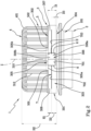
- the numeral 1 denotes a cap for closing a container 2, of which only a neck 201 is shown, particularly a bottle designed to contain a liquid substance such as a drink.
- the cap 1 is made of polymeric material. Any polymeric material designed to be moulded can be used to obtain the cap 1.
- the cap 1 is shown in Figure 1 in a closed condition in which the cap 1 is located when it leaves a cap production line and is applied to the neck 201 of the container 2, in combination with it.
- the cap 1 comprises a lateral wall 3 which extends about an axis Z, and a transversal wall 4 positioned at one end of the lateral wall 3, so as to close the end.
- the transversal wall 4 extends transversally, in particular perpendicularly, to the axis Z.
- the transversal wall 4 may be flat, even though other shapes are theoretically possible. In the example illustrated, the transversal wall 4 has a substantially circular shape in plan view.
- the lateral wall 3 and the transversal wall 4 define a cup-shaped body, designed to receive an end portion of the neck 201 of the container 2, so that the cap 1 can close the container 2.
- the lateral wall 3 is connected to the transversal wall 4 by a connecting zone 401, which may be shaped, in cross section, like a bevelled edge or a circular connector.
- the cap 1 comprises a separation line 5, which is provided on the lateral wall 3 to define a retaining ring 301, which is configured to remain anchored to the neck 201 of the container 2.
- the retaining ring 301 is configured to engage internally with a locking ring 202, which projects from an outer surface of the neck 201, in such a way as to remain anchored to the neck 201.
- the locking ring 202 is an annular enlargement, which extends in a plane positioned transversally to the axis Z.
- the separation line 5, on the lateral wall 3, defines, in addition to the retaining ring 301, a closing element 302 removably engageable with the neck 201, so as to open or close the container 2.
- the closing element 302 can be engaged for closing a dispensing opening 203 of the container 2.
- the separation line 5 extends about the axis Z and is circumferentially interrupted so as to leave the retaining ring 301 and the closing element 302 joined together. More in detail, the separation line 5 extends between a first end 501 and a second end 502.
- the separation line 5 may have an angular extension, about the axis Z, greater than or equal to 240° and less than, or equal to, 350°.
- the angular extension of the separation line 5 may be between 250° and 340°, preferably between 320° and 330°.
- the expression "the angular extension is between” 250° and 340° means, in all this document, that it may be greater than, or equal to, 250° and less than, or equal to, 340°, in other words, the ends of the range indicated are always included therein and are not excluded.
- the retaining ring 301 comprises a retaining portion 303, which is configured to engage internally with the locking ring 202 and extends up to a free edge 304 of the retaining ring 301.
- the free edge 304 delimits the retaining ring 301 on the side opposite the transversal wall 4.
- the retaining ring 301 therefore extends between the separation line 5 and the free edge 304 and may be delimited by a cylindrical or truncated cone shaped outer surface.
- the separation line 5 is parallel to the free edge 304.
- the retaining portion 303 is a lower portion of the retaining ring 301, and therefore of the cap 1, when the cap is joined to the container 2 and is configured to retain anchored the retaining ring 301 to the neck 201 of the container 2.
- the retaining ring 301 in addition comprises:
- first connecting band 306 and the second connecting band 307 extend from end zones 305a, 305b circumferentially opposite the joining portion 305 up to the retaining portion 303.
- the first connecting band 306 extends from a first end zone 305a of the joining portion 305 to the retaining portion 303
- the second connecting band 307 extends from a second end zone 305b of the joining portion 305 to the retaining portion 303, the second end zone 305b being circumferentially opposite the first end zone 305a.
- the first end zone 305a and the second end zone 305b of the joining portion 305 are respectively immediately adjacent to the first end 501 and to the second end 502 and are therefore positioned circumferentially on the opposite side in the joining portion 305.
- the first connecting band 306 and the second connecting band 307 are therefore positioned circumferentially on the opposite side in the joining portion 305.
- the retaining ring 301 comprises a tab 308.
- the tab 308 is circumferentially interposed between the first connecting band 306 and the second connecting band 307 and protrudes towards the free edge 304 so that, when the container 2 is in the open condition and the first connecting band 306 and the second connecting band 307 keep the closing element 302 connected to the retaining ring 301, the tab 308 can rest on the neck 201 of the container 1.
- the tab 308 is interposed between the connecting bands 306, 307 and protrudes relative to the first end zone 305a and the second end zone 305b of the joining portion 305 towards the free edge 304.
- the tab 308 rests on the neck 201 for locking the closing element 302 spaced from the neck.
- the tab 308 is made exclusively as an outer part 308a, projecting relative to the first end zone 305a and to the second end zone 305b.
- the separation line 5 is positioned at a distance D1 along an axis parallel to the axis Z from the free edge 304 of the retaining ring 301.
- the height of the retaining ring 301 along an axis parallel to the axis Z is therefore equal to D1.
- the distance D1 is less than or equal to 6.5 mm. Preferably, the distance D1 is less than or equal to 5 mm.
- the distance D1 is greater than or equal to 2 mm. Preferably, the distance D1 is greater than or equal to 3 mm.
- the distance D1 is between 3 and 5 mm.
- H denotes a height of the tab 308, which H1 denotes a height of the connecting bands 306, 307 and that D2 denotes a height of the retaining portion 303, along an axis parallel to the axis Z when the closing element 302 is in the closed condition.
- the closing element 302 can rotate relative to the neck 201 of the container 2 around the joining portion 305, which defines in this way a hinge band which keeps connected the closing element 302 relative to the neck 201, deforming.
- joining portion 305, the first connecting band 306, the second connecting band 307 and the tab 308 are joined together and define a hinge arrangement which has a capacity of movement, in an axial direction, considerably greater than the capacity of movement which would be allowed only by the joining portion 305, as described in more detail below.
- the hinge arrangement is a part of the retaining ring 301 which is interposed between the retaining portion 303 of the retaining ring 301 and the closing element 302.
- the tab 308 is, in effect, connected to the lateral wall 3 by a hinge line 310, about which the tab 308 can optionally bend for resting on the neck 201 close to the locking ring 202.
- hinge line 310 is a virtual line which defines in the lateral wall 3 a zone about which the tab 308 may optionally bend, which may also be part of the hinge band of the joining portion 305, relative to the height H of the tab 308, or positioned closer to the free edge 304, or also on the lateral wall 3, as described in more detail below.
- the bottom edge 309 is a free edge of the tab 308, which is positioned on the opposite side relative to the hinge line 310.
- the bottom edge 309 is able to intercept the neck 201 of the container 2 without interference by the first connecting band 306 and the second connecting band 307, which remain withdrawn relative to it.
- an angle of opening is defined at least equal to 30°, which guarantees that the closing element 302 does not interfere with the dispensing of the contents of the bottle when the bottle is inclined.
- the closing element 302 is positioned inclined and the shape of the locking ring 202 and/or the retaining ring 301 and/or the tab 308 can contribute to determining the inclination of the closing element 302, as described in more detail below.
- the joining portion 305 has a thickness S substantially constant on a plane containing the separation line 5. In effect, no lightening or particular shapes of zones of the lateral wall of the cap 1 are necessary to make the joining portion 305.
- each connecting band 306, 307 may have a radial thickness S, that is to say, a thickness measured in a radial direction relative to the axis Z, greater than, or equal to, 0.35 mm. This thickness may be less than, or equal to, 1.8 mm.
- the radial thickness S of each connecting band 306, 307 may be greater than, or equal to, 0.5 mm. This thickness may be less than, or equal to, 1.2 mm.
- the radial thickness S of the connecting bands 29, 30 may be, preferably, constant in a direction parallel to the axis Z.
- the radial thickness S of the connecting bands 306, 307 may be variable in a direction parallel to the axis Z.
- the radial thickness S of the connecting bands 306, 307 may vary along a direction parallel to the axis Z, in such a way as to remain inside the intervals indicated above.
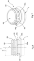
- the locking ring 202 ( Figure 6 ) has a triangular cross-section and has an upper wall 202a, facing towards the dispensing opening 203, which is inclined relative to a base wall 202b of the locking ring 202 facing towards a bottom of the container 2.
- the locking ring 202 has, in other words, the upper wall 202a with a frustoconical shape.
- a cylindrical wall (not illustrated) of the locking ring 202 may be interposed between the upper wall 202a and the base wall 202b.
- An angle ⁇ of 50° is defined between an axis parallel to the axis Z, passing through an outer edge of the locking ring 202 and the upper wall 202a.
- the inclination of the closing element 302 in the open condition may depend on:
- the inclination of the closing element 302 in the open condition, and therefore the stability in the locking of the same on the neck 201 is also determined by a ratio between the height H1 of the connecting bands 306, 307 and the radial thickness S of the connecting bands 306, 307, as described in more detail below, which can deform to guarantee the optimum connection between the neck 201 and the joining portion 305 (and if necessary between the neck 201 and the connecting bands 306, 307) in such a way as to maintain the closing element 201 in the open position in a reliable and secure fashion.
- the separation line 5 extends on a plane positioned transversally, in particular perpendicularly, to the axis Z. It should be noted that the retaining ring 301 and the closing element 302 are positioned on opposite sides of the separation line 5.
- the lateral wall 3 of the cap 1 is provided internally with a coupling structure (not illustrated), configured for removably couple the closing element 302 to the neck 201 of the container 2, in such a way that the cap 1 can be moved from the closed condition, wherein the cap 1 closes the dispensing opening 203 of the container 2, to the open condition.
- the coupling structure of the cap 1 is positioned inside the closing element 302 and is shaped to engage with a corresponding coupling structure 204 present externally on the neck 201 of the container 2.
- the coupling structure of the closing element 302 and the coupling structure 204 of the neck 201 are, as illustrated in the accompanying drawings, made as a thread. In this case, the movement from the closed condition to the open condition is performed by a rotation of the closing element 302 relative to the neck 201 of the container 2.
- the tab 308 rests on the neck 201 close to the locking ring 202.
- the inclination of the closing element 302 relative to the neck 201 is determined, which in turn determines the resting of the tab 308 on the neck 201.
- the tab 308 can rest on the neck 201 in different positions of the neck. For example, the tab 308 can be rested:
- the lateral wall 3 can be provided, on a relative outer surface, with a plurality of knurling lines 312, extending parallel to the axis Z and designed to facilitate gripping of the cap 1 by the user or by the capping machine which applies the cap 1 on the container 2 to be closed.
- the knurling lines 312 may be positioned in the closing element 302 but may also continue in the connecting zone 401 and/or in the retaining ring 301.
- the lateral wall 3 comprises a cylindrical portion extending up to the connecting zone 401, on which the knurling lines 312 are made, a wide portion extending up to the free edge 304 of the retaining ring 301 and a connecting portion positioned between the cylindrical portion and the wide portion.
- the wide portion has a diameter greater than the cylindrical portion.
- the wide portion may be delimited by a smooth outer surface, that is to say, it may be without knurling lines 312 but this is not necessary since the knurling lines 312 could also extend on the wide portion.
- the closing element 302 is defined by the cylindrical portion, the retaining ring 301 is formed by the wide portion since the separation line 5 is provided on the connecting portion.
- other configurations of the cap 1 might be possible, in relation to the position of the separation line 5 and the extension of the knurling lines 312.
- the separation line 5 may be positioned on the cylindrical portion.
- breakable bridges 503 are designed to be broken the first time the cap 1 is moved to the open position, to signal that the container is no longer whole. In this way, the closing element 302 separates from the retaining ring 301 along the separation line 5.
- the retaining ring 301 is configured to engage internally with the locking ring 202 in such a way as to remain anchored to the neck 201.
- the retaining ring 301 is provided internally with an engagement element 313, shown in Figure 4 and in Figure 17 , designed to engage with the locking ring 202.
- the engagement element 313 is configured for making contact against the locking ring 202 so as to prevent axial movements of the retaining ring 301, away from the neck 202, when the closing element 301 is removed from the neck 201.
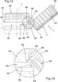
- the retaining portion 303 of the retaining ring 301 to be provided with the engagement element 313, in such a way as to be retained anchored to the locking ring 202 even when, as illustrated in Figures 1A and 1B , the closing element 302 is in the open condition and is locked spaced from the neck 201 and from the dispensing opening 203.
- the engagement element 313 is shaped like an annular element which is folded around the free edge 304 towards the inside of the retaining portion 303. More in detail, the annular element may be continuous or interrupted. In effect, there may be a plurality of folded elements, shaped like flaps, which project from the free edge 304 and are folded towards the inside of the retaining portion 303 for making the engagement element.
- the engagement element 313 may be shaped like a continuous enlargement or interrupted, not illustrated, which from an inner surface of the retaining portion 303 projects towards the axis Z to engage with the locking ring 202, provided the enlargement does not affect the tab 308.
- the tab can bend about the hinge line 310.
- the bottom edge 309 is transversal, in particular perpendicular to the axis Z, the lateral edges 311 are transversal to the bottom edge 309.
- the lateral edges 311 are parallel to each other, parallel to the axis Z and perpendicular to the bottom edge 309.
- the tab 308 has a preferably rectangular shape wherein the bottom edge 309 is the free edge and, on the opposite side, has the hinge line 310.
- the cut lines 6 from which it is possible to obtain the lateral edges 311 are also curved.
- the cut lines 6 have the same height and have first ends, facing towards the transversal wall 4, between which the hinge line 310 is defined.
- the hinge line 310 is positioned in the joining portion 305 of the lateral wall 3.
- the tab 308 projects relative to the first end zone 305a and to the second end zone 305b of the joining portion 305 and in effect has only an outer part 308a.
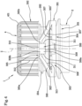
- Figures 2 to 5 show a version of the cap 1 which differs from the version of Figure 1 in that the tab 308 has, in addition to the outer part 308a, protruding relative to the first end zone 305a and to the second end zone 305b of the joining portion 305, also an inner part 308b, made in the joining portion 305.
- the hinge line 310 is positioned, also in this case, on the joining portion 305 of the lateral wall 3 but close to, or aligned with, the first end 501 and the second end 502 of the separation line 5.
- the inner part 308b is interposed between the first connecting band 306 and the second connecting band 307 and is separated from the connecting bands 306, 307 by respective stretches of the lateral edges 311.
- the tab 308 has a greater capacity to bend about the hinge line 310 since it has a greater height H.
- the cut lines 6 extend inside the joining portion 305 to define the inner part 308b of the tab 308.
- the tab 308 in addition to the inner part 308b, comprises an additional part made in the closing element 302 and separated from the latter by respective further stretches of the lateral edges 311.
- the hinge line 310 of the tab 308 is positioned in the closing element 302 of the lateral wall 3, since the cut lines 6 extend beyond the joining portion 305, and that is, beyond the retaining ring 301, inside the closing element 302 to define the additional part of the tab 308.
- This version of the tab 308 has even greater capacity to bend since the height H of the tab 308, from the hinge line 310 to the bottom edge 309, is increased.
- the cut lines 6 might extend up to the knurling lines 312 of the closing element 302 to obtain a hinge line 310 positioned at the knurling lines 312.
- the connecting bands 306, 307 are made by means of an incision line 7, shown in Figures 1 and 2 , which extends between the separation line 5 and the free edge 304 of the retaining ring 301.
- the incision line 7 has an angular extension, measured about the axis Z, greater than the angular distance (also measured about the axis Z) between the first end 501 and the second end 502 of the separation line 5, that is to say, the angular extension of the joining portion 305.
- the incision line 7 comprises a first lateral stretch 702 and a second lateral stretch 703 which partly define, respectively, the first connecting band 306 and the second connecting band 307.
- first lateral stretch 702 and the second lateral stretch 703 are both perpendicular to the axis Z and are aligned.
- the two lateral stretches 702 and 703 might be slightly inclined relative to each other and have different inclinations, not necessarily parallel to each other.
- the first lateral stretch 702 and the second lateral stretch 703 extend, preferably, on a first plane (not illustrated) parallel to a separating plane (not illustrated) containing the separation line 5, the first plane being transversal to the axis Z, in particular perpendicular to the axis Z.
- the first lateral stretch 702 and the second lateral stretch 703 respectively define a first free lower edge 306' and a second free lower edge 307' of the connecting bands 306, 307.
- first lateral stretch 702 and the second lateral stretch 703 also define a first free upper edge 303' and a second free upper edge 303" of the retaining portion 303.
- the first lateral stretch 702 and the second lateral stretch 703 are positioned at the distance D2 from the free edge 304 of the retaining ring 301, along an axis parallel to the axis Z, which corresponds to the height of the retaining portion 303.
- the distance D2 may be greater than or equal to 1 mm.
- the distance D2 may be less than or equal to 5 mm. More specifically, the distance D2 may be less than or equal to 4 mm.
- the distance D2 may be between 1 and 3 mm.
- the distance D2 may be equal to 3.9 mm.
- the height H1 of the connecting bands 306, 307 may be greater than, or equal to, 1 mm and less than, or equal to, 5.5 mm.
- the connecting bands 306, 307 may have a height H1 greater than, or equal to, 1.2 mm and less than, or equal to, 4 mm.
- the height H1 may be variable from 1.2 mm to 3.5 mm.
- the height H1 may be equal to 2 mm.
- the cap 1 may have a height H2, measured in a direction parallel to the axis Z, variable between 10 and 21 mm.
- connecting bands 306, 307 comprise a first portion adjacent to the separation line 5, and a second portion adjacent to the incision line 7.
- the height H1 of the connecting bands 306, 307 is constant along the entire length of the connecting bands 306, 307 and is equal for the two connecting bands 306, 307.
- the first connecting band 306 is formed between a first end stretch of the separation line 5 and the first lateral stretch 702 of the incision line 7.
- the second connecting band 307 is formed between a second end stretch of the separation line 5 and a second lateral stretch 703 of the incision line 7.
- the first end stretch of the separation line 5 is a stretch which extends up to the first end 501.
- the second end stretch is a stretch which extends up to the second end 502.
- the first lateral stretch 702 and the second lateral stretch 703 extend up to the cut lines 6.
- Each lateral stretch 702, 703 of the incision line 7, both the first lateral stretch 702 and the second lateral stretch 703, may have an angular extension about the axis Z of between 20° and 110°, preferably between 30° and 70°, even more preferably between 50° and 60°.
- each lateral stretch 702, 703 has an angular extension about the axis Z of between 20° and 90°.
- the incision line 7 comprises a central stretch 701 which is interposed between the first lateral stretch 702 and the second lateral stretch 703.
- the central stretch 701 extends on a second plane, parallel to the plane of separation and interposed between the first plane and the free edge 304 of the retaining ring 301, and defines the bottom edge 309 of the tab 308.
- the connecting bands 306, 307 and the tab 308 are made by means of the separation line 5 and the incision line 7 which lie in three planes parallel to each other, that is to say, the separation line 5 lies in the separation plane, whilst the incision line 7 lies, with regard to the two lateral stretches 702 and 703 in the first plane, and, with regard to the central stretch 701, in the second plane.
- the central stretch 701 is positioned at a distance D3 along an axis parallel to the axis Z from the free edge 304 of the retaining ring 301.
- the distance D3 may be less than, or equal to, 3 mm. More specifically, the distance D3 may be less than, or equal to, 1 mm.
- the cut lines 6 have second ends between which extends the central stretch 701 of the incision line 7.
- the distance between the first ends of the cut lines 6 and the central stretch 701 of the incision line 7 defines the height H of the tab 308, along an axis parallel to the axis Z, which corresponds to the distance between the hinge line 310 and the bottom edge 309 of the tab 308.
- the central stretch 701 which determines the width of the tab 308, has an angular extension about the axis Z of between 10° and 120°, preferably between 15° and 70°, more preferably between 20° and 50°, even more preferably between 30° and 40°, even more preferably equal to 25°.
- the tab 308 is sufficiently flexible about the hinge line 310 and the connecting bands 306, 307 are sufficiently long to allow the closing element 302 to be moved axially to move the tab 308 beyond an upper edge of the neck 201, when the cap 1 is opened, and to move the tab 308 to disengage from the locking ring 202, when the cap 1 is closed.
- the incision line 7, and that is, the central stretch 701, the first lateral stretch 702 and the second lateral stretch 703, may be preferably shaped like an incision, that is to say, a cut line, passing through the entire thickness of the lateral wall 3, and that is to say, of the retaining ring 301.
- the incision line 7 may be shaped like a line of weakness not passing through the entire thickness of the lateral wall 3, but at which the thickness of the lateral wall 3 is very reduced relative to the surrounding zones to facilitate the fracture of the incision line 7 in the retaining ring 301.
- the incision line 7 there may also be breakable elements 704, shown in Figures 14 and 15 , which may be similar and angularly aligned with the breakable bridges 503 or be misaligned relative to them.
- the breakable bridges 503 may be angularly offset about the axis Z relative to the breakable elements 704.
- the joining portion 305 has an angular extension about the axis Z of between 10° and 120°, preferably between 30° and 110°, even more preferably between 20° and 40°.
- the joining portion 305 has an angular extension of between 10° and 120°, preferably between 20° and 40°.
- a closing cap 1 could have a joining portion 305 with an angular extension equal to 40°, a tab 308 with an angular extension equal to 25° and the first lateral stretch 702 and the second lateral stretch 703 with an angular extension of between 50° and 60°.
- This type of cap 1 has a tab 308 which has an angular extension less than the angular extension of the joining portion 305 and has wide connecting bands 306, 307.
- the closing cap 1 could have a joining portion 305 with an angular extension of between 90° and 120°, a tab 308 of angular extension of between 90° and 120° and the first lateral stretch 702 and the second lateral stretch 703 of angular extension each between 20° and 35°.
- the joining portion 305 has a centre line which coincides with the centre line of the tab 308. Moreover, the first lateral stretch 702 and the second lateral stretch 703 have an equal angular extension in such a way that the connecting bands 306, 307 are equal in length and are positioned symmetrically relative to a plane containing the axis Z and the centre line of the joining portion 305.
- the first connecting band 306 may be of different length relative to the second connecting band 307, since the first lateral stretch 702 and the second lateral stretch 703 may have a different angular extension.
- the centre line of the joining portion 305 may also not coincide with the centre line of the tab 308.
- the cap 1 is applied on the neck 201 of the container 2 in the closed condition shown in Figure 1 , or Figure 2 .
- the cap 1 is positioned in such a way that the engagement element 313 provided inside the retaining ring 301, in particular on the retaining portion 303 is below the locking ring 202 present on the neck 201.
- the user grips the closing element 302 and rotates the closing element 302 about the axis Z, in order to unscrew the closing element 302 from the neck 201.
- the closing element 302 and the retaining ring 301 are rotated together about the axis Z, and they simultaneously move together in a direction parallel to the axis Z, away from the neck 201.
- the closing element 302 which is unscrewed by the user, continues to move along the axis Z away from the neck 201.
- the breakable bridges 503 are thereby tensioned, until causing the failure.
- the closing element 302 consequently separates from the retaining ring 301 along the separation line 5, but remains joined to the retaining ring 301 at the joining portion 305.
- the first connecting band 306 and the second connecting band 307 deform since they extend between the retaining portion 303, locked by the locking ring 202, and the joining portion 305, integral with and joined to the closing element 302, which has moved away from the locking ring 202 and raised upwards.
- the tab 308, which protrudes relative to the first end zone 305a and to the second end zone 305b of the joining portion 305 also moves away from the locking ring 202 whilst the first connecting band 306 and the second connecting band 307 are pulled upwards.
- the breakable elements 704 are thus tensioned until they break. Consequently, the first connecting band 306 and the second connecting band 307 are spaced both from the closing element 302 and from the retaining portion 303 and remain joined to each other in the joining portion 305.
- the first connecting band 306 and the second connecting band 307 thus adopt the shape of a trapezium shown in Figure 4 . It may be noted that the tab 308 is positioned centrally, in the smaller base of the trapezium, and projects towards the free edge 304 of the retaining ring 301.
- the trapezium is of the isosceles type. If, on the other hand, the connecting bands 306, 307 have a different length, they will adopt a shape of the scalene trapezium type. With regard to the position of the tab 308 in the joining portion 305, the tab 308 can protrude centrally or laterally from the latter.
- the first connecting band 306 remains joined to the retaining portion 303 at the outer end of the first lateral stretch 702 of the incision line 7.
- the second connecting band 307 remains joined to the retaining portion 303 at the outer end of the second lateral stretch 703 of the incision line 7, the outer end of the first lateral stretch 702 and the outer end of the second lateral stretch 703 delimiting externally the incision line 7 circumferentially. If the first connecting band 306 and the second connecting band 307 are arranged in an inclined configuration relative to the retaining portion 303 and converge in the joining portion 305, the tab 308 extends along an axis which is parallel to the axis Z.
- the closing element 302 is disengaged from the coupling structure, or thread, 204 made on the neck 201, so that the container 2 can be opened.
- the retaining portion 303 of the retaining ring 301 remains, on the other hand, anchored to the neck 201.
- the closing element 302 Since the tab 308 protrudes relative to the joining portion 305, in order to be able to completely disengage the tab 308 from the neck 201 of the container 2, the closing element 302 must be further moved away from the neck 201. However, the tab 308 may also bend relative to the hinge line 310 to disengage its bottom edge 309 from the upper edge of the neck 201.
- the joining portion 305 defines a hinge band, which keeps connected the closing element 302 relative to the neck 201 and about which the closing element 302 can rotate away from the neck 201.
- the bottom edge 309 of the tab 308 intercepts the neck 201 of the container 2, as mentioned above. More in detail, the tab 308 rests in the proximity of the locking ring 202 of the neck 201 since the locking ring 202 prevents the tab 308 from rotating further.
- the bottom edge 309 of the tab 308 faces towards the dispensing opening 203 of the container 2 and the tab 308 prevents the closing element 302 from accidentally rotating again towards the neck 201 and about it.
- the joining portion 305 defines the hinge band which deforms to allow the rotation of the closing element 302 relative to the neck 201 and the connecting bands 306, 307 comprise the first portion adjacent to the separation line 5, and the second portion adjacent to the incision line 7.
- the first portion widens radially, without undergoing a substantial twisting.
- the second portion may, on the other hand, be twisted to pass under the first portion, interposing between the first portion and the outer surface of the neck 201. In this way, when the tab 308 is resting on the neck 201 so that the bottom edge 309 of the tab 308 faces towards the dispensing opening 203 of the container 2, the second portion of the connecting bands 306 and 307 is twisted and is below the first portion.
- the ratio between the height H1 of the connecting bands and the radial thickness S of the connecting bands 306, 307 may therefore be greater than, or equal to, 1.4.
- the above-mentioned ratio may be less than or equal to 5.1.
- the ratio between the height H of the connecting bands and the radial thickness R of the connecting bands may be less than, or equal to, 6.5.
- connecting bands 306, 307 have an optimum torsional rigidity to deform as explained above, by twisting which affects at least a part of the height H1 of each connecting band, and to generate an interference between the neck 201 and the joining portion 305 (and, if necessary, between the neck 201 and the connecting bands 306, 307)sufficient to keep the closing element 302 in the open position in a reliable and secure manner.
- the twisting of the connecting bands 306, 307 together with the resting of the tab 308 on the neck reinforces the closing element 302 in the open condition.
- the first hinge element and the second hinge element are, respectively, immediately adjacent to the first end 501 and to the second end 502 of the joining portion and are therefore positioned circumferentially on the opposite side.
- the closing element 302 remains in the open condition thanks to the presence of the interference between tab 308 and neck 201.
- the user can return the cap 1 to the closed condition shown in Figure 1 , and in Figure 2 , by a sequence of operations opposite to that described above.
- the user In order to disengage the tab 308 from the locking ring 202, the user must firstly move the closing element 302 away from the neck 201, deforming the first connecting band 306 and the second connecting band 307, in the same direction of inclination of the upper wall 202a of the locking ring 202, if the tab 308 has rested on the locking ring 202, or between the connecting structure 204 and the locking ring 202.
- the particular shape of the hinge arrangement and that is to say, of the connecting bands 306 and 307, of the joining portion 305 and of the tab 308 is particularly suitable for being deformed in a direction of inclination parallel to the upper wall 202a, so that the user can disengage the tab 308 by sliding it on the upper wall 202a of the locking ring 202 when pulling the closing element 302 away from the container 2.
- the hinge arrangement according to the invention including the tab 308, may also be advantageously applied to containers 2 having a locking ring 302 of different shape.
- the user can reapply the closing element 302 on the neck 201, rotating the closing element 302 around the joining portion 305 and axially moving the closing element 302 away from the neck 201, before screwing again the closing element 302 on the thread 204.
- the tab 308 is not an obstruction since it is positioned parallel to the outer surface of the neck 201.
- the cap 1 may be obtained starting from a concave body 8, shown in Figure 16 , which comprises the lateral wall 3 and the transversal wall 4.
- the concave body 8 may be produced by moulding a polymeric material, for example compression moulding or injection moulding.
- the separation line 5 and the incision line 7 are made on the lateral wall 3.
- a cutting unit 9 comprising cutting tools, which may, for example, be blades 901a positioned perpendicularly to the axis Z, to make the separation line 5 and the incision line 7, or blades 901b positioned parallel to the axis Z to make the cut lines 6.
- the cutting unit 9 may be located downstream of a mould in which the concave body 8 has been formed. These cutting operations may be performed by means of respective blades, for example circular or linear, which interact with the lateral wall 3 from the outside of the latter, or from the inside.
- the concave body 8 can be rotated about the axis Z of the lateral wall 3, whilst the blades 901a, 901b are kept stationary, so as to bring consecutive zones of the lateral wall 3 to interact, in succession, with the blades 901a and/or 901b.
- FIG. 16 shows the cutting unit 9 which comprises an outer surface, not illustrated, which extends around the concave body 8 and is shaped to surround externally the lateral wall 3 of the concave body 8.
- the outer surface comprises a first portion 902a configured to support the cutting tools 901, and a second portion 902b configured to allow the rotation of the concave body 8 about its own axis Z.
- the first portion 902a and the second portion 902b are configured to superimpose in a direction parallel to the axis Z and the concave body 8 is configured to be placed in rotation in such a way as to be pushed against the first portion 902a and the second portion 902b.
- the cutting unit 9 also comprises a planar base 903 on which the concave body 8 rests, and more precisely, the transversal wall 4.
- the second portion 902b has a plurality of respective knurling lines (not illustrated), which are complementary to the shape of the plurality of knurling lines 312 of the concave body 8.
- the cutting unit 9 comprises a spindle 904 which is smaller in diameter than the concave body 8 and is idly rotatable about its own axis Z1, parallel to the axis Z.
- a head 904a of the spindle 904 is configured to be received in the concave body 8 and comprises a contact ring 905 made of polymeric material fixed in the spindle 904 in a position such as to make contact with the lateral wall 3 of the concave body 8.
- the spindle 90 in a manner not illustrated, is fixed to a carousel rotatable about a respective axis which is parallel to the axis Z and Z1.
- the head 904a of the spindle 904 pushes against the lateral wall 3 of the concave body 8 which is therefore pushed against the first portion 902a and the second portion 902b of the outer surface 902.
- the motion of the carousel about its axis causes the spindle 904 to rotate and the latter causes the rolling of the concave body 8, and more precisely of the first portion of the lateral wall 3 on the first portion 902a of the outer surface 902.
- the cutting tools 901 fixed to the first portion 902a, intercept the lateral surface 3 and make contact with the ring 905 whilst the lateral wall 3 is kept pushed by the head 904a of the spindle 904 against the first portion 902a.
- the contact ring 905 guarantees an effective and precise cut of the lateral wall 3.
- the blades which make it possible to obtain the separation line 5 and the incision line 7 may be configured to interact with the lateral wall 3 on respective parallel planes, for example perpendicular to the axis Z, if, as in the examples shown above, it is desired that the separation line 5 and the incision line 7 lie in respective parallel planes.
- the cutting tools 901a are blades parallel to each other which are angularly distributed along the first portion in such a way that during rotation the concave body 8 they intercept in succession the blades to define the separation line 5 and/or the incision line 7.
- the blades 901a may have an interrupted cutting edge, if it is desired that, along the separation line 5, the breakable bridges 503 remain defined and/or that along the incision line 7 respective breakable elements 704 remain defined.
- the method also comprises the step of:
- a retaining portion 303 which is configured to engage internally with a locking ring 202 of the neck 201 and extends up to a free edge 304 of the retaining ring 301, the first connecting band 306 extending from a first end zone 305a of the joining portion 305 to the retaining portion 303, and a second connecting band 307, extending from a second end zone 305b of the joining portion 305 to the retaining portion 303.
- the method comprises the step of providing a first end zone 305a of the joining portion 305, from which extends the first connecting band 306 to the retaining portion 303, a second end zone 305b of the joining portion 305, from which extends the second connecting band 307 to the retaining portion 303, the second end zone 305b being positioned circumferentially on the opposite side relative to the first end zone 305a.
- the method comprises the step of making an incision line 7, which extends between the separation line 5, and the free edge 304, which comprises the step of making a first lateral stretch 702 and a second lateral stretch 703 of the incision line 7, transversally to the axis Z in a first plane parallel to a plane of separation containing the separation line 5.
- a first free lower edge 306' of the first connecting band 306 may be defined, a second free lower edge 307' of the second connecting band 307, a first free upper edge 303' and a second free upper edge 303" of the retaining portion 303.
- the method also comprises the step of making a central stretch 701 of the incision line 7, interposed between the first lateral stretch 702 and the second lateral stretch 703 in a second plane parallel to the separating plane and interposed between the first separating plane and the free edge 304 of the retaining ring 301.
- a bottom edge 309 of the tab 308 may be defined.
- the method comprises the step of using cutting tools 901a positioned transversally to the axis Z.
- the method comprises the step of making the separation line 5 and the incision line 7 on three planes which are separate from each other.
- the incision line 7 may be obtained with horizontal cutting tools 901a, after the cap 1 has been made, that is to say, with horizontal blades.
- the method comprises the step of cutting the separation line 5 and the incision line 7 using cutting tools which have a cutting edge interrupted to define, respectively, a plurality of breakable bridges 503 along the separation line 5 and optionally to define a plurality of breakable elements 704 along the incision line 7 or comprises the step of cutting the separation line 5 and the incision line 7 using cutting tools having a flat cutting edge.
- the cut lines 6 can be obtained with vertical cutting tools 901b and that is to say, vertical blades can be used after the cap 1 has been made.
- the horizontal blades may be used in a first cutting station, not illustrated, and the vertical blades in a second cutting station, not illustrated, that is to say, to cut horizontally and vertically in succession the cap 1 grouping together the cutting tools 901a transversal to the axis Z and the cutting tools 901b parallel to the axis Z.
- the cutting tools 901a may also be suitably positioned transversally to the axis Z and/or the cutting tools 901b positioned parallel to the axis Z in such a way as to make angularly in succession the separation line 5, the incision line 7 and the cut lines 6.
- the separation line 5 can be used since the separation line 5, the incision line 7 and the cut lines 6 can be made as cut lines by means of a cutting operation in a simple and inexpensive manner on the cap 1, shaped as a concave body, after the latter has been formed.
- the method according to the invention therefore comprises forming a concave body 8 which comprises a lateral wall 3 extending about an axis Z and a transversal wall 4 positioned at one end of the lateral wall 3 and cutting by means of cutting tools 901a, preferably from the outside of the concave body 8, or optionally from the inside, the separation line 5 and the incision line 7 in the lateral wall 3, rotating the concave body 8 and keeping the cutting tools stationary or optionally keeping the concave body 8 stationary and rotating the cutting tools 901a about it.
- the method also comprises pushing the concave body 8 using a spindle 904 provided with a contact ring 905 made of polymeric material in such a way that a first portion of the lateral wall 3 pushes against a first portion 902a of an outer surface provided with cutting tools 901a and/or 901b and that a second portion of the lateral wall 3, provided with knurls 312, engages the knurls present in a second portion 902b of the outer surface, shaped complementary to the knurls 312 of the lateral wall 3.
- the method also comprises rotating the spindle 904 in such a way that the concave body 8 rolls on the first portion 902a of the outer surface drawn by the meshing between the second portion of the lateral wall 3 on the second portion 902b of the outer surface.
- This version of the cap 1 differs from the cap 1 of Figure 2 only in that it has a locking ring 301', formed on the lateral wall 3 by a separation line 5', in which there are connecting bands 306, 307, which are made by means of an incision line 7', which comprises a first lateral stretch 702' and a second lateral stretch 703' which respectively define the first free lower edge 306' and the second free lower edge 307' of the first connecting band 306 and of the second connecting band 307, wherein the first lateral stretch 702' and the second lateral stretch 703' are suitably positioned.
- first connecting band 306 and the second connecting band 307 also extend from the joining portion 305 to the retaining portion 303 and the tab 308 is circumferentially interposed between the first connecting band 306 and the second connecting band 307 and projects towards the free edge 304.
- the locking ring 202 projects from an outer surface of the neck 201, has an upper wall 202a facing towards the dispensing opening 203, having a truncated cone shape, and a base wall 202b facing towards a bottom of the container 2.
- the locking ring 202 extends in a direction parallel to the axis Z between an upper end 202c, closest to the dispensing opening 203 of the neck 201 and a lower end, positioned on the opposite side to the dispensing opening 203, which coincides in the case shown with the base wall 202b. It should be noted, however, that if the locking ring 202 has shapes different to the truncated cone shape, the lower end may not coincide with the base wall 202b.
- the first lateral stretch 702' and the second lateral stretch 703' of the incision line 7' are positioned beyond the lower end 202b of the locking ring 202, towards the dispensing opening 203, if we consider a direction parallel to the axis Z, or at the lower end, when the closing element 302 is in a closed condition.
- the first lateral stretch 702' and the second lateral stretch 703' lie on this plane or in the half-space facing towards the dispensing opening 203.
- the tab 308 can rest on the neck 201 beyond the upper end of the locking ring towards the dispensing opening 203.
- the tab 308 may be supported to rest, for example, in the outer zone of the neck 201 between the locking ring 202 and a lower thread of the coupling structure 204, or precisely on the coupling structure 204 in relation to the shape of the retaining ring 301, 301' and/or of the locking ring 202 and/or of the tab 308.
- the tab 308 may be moved to rest, for example, beyond the upper end 202c of the locking ring 202, for example between the upper end 202c and a thread of the coupling structure 204 or precisely on the coupling structure 204.
- the retaining ring 301' differs from those described above in that it has a height D1 greater than those shown in Figures 1 to 7 , in a direction parallel to the axis Z.
- the separation line 5' is positioned, when the closing element 302 is in a closed condition, beyond the upper end 202c of the locking ring 202 in a direction parallel to the axis Z towards the dispensing opening 203, or at the upper end 202c.
- the separation line 5' lies on this plane or in the half-space facing towards the dispensing opening 203.
- the tab 308 can rest on the coupling structure 204 when the closing element 302 is in the open condition.
- the height H1 of the connecting bands 306, 307 may be maintained equal to that of the cap of Figures 1 to 7 , with consequent robustness of the connecting bands 306, 307.
- the hinge band comprises a first hinge element and a second hinge element defined at least partly, respectively, in the first end zone 305a and in the second end zone 305b of the joining portion 305 and the deformation affects exclusively the first hinge element and the second hinge element but not the connecting bands 306, 307, which therefore remain substantially undeformed and do not twist.
- the method for making the cap of Figures 8 to 11 is also similar to that described with reference to Figures 1 to 7 and Figure 16 , which will, however, be performed by cutting the separation line 5' and the incision line 7', that is to say, the first central stretch 701', the first lateral stretch 702' and the second lateral stretch 703' of the incision line 7 respectively at suitable distances D1, D2 and D3.
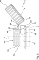
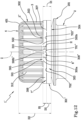
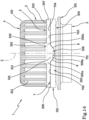
- FIGS 12 and 13 show a version of the cap 1' according to the second aspect of the invention.
- the cap 1' differs from the cap 1 of Figures 2 to 11 in that it has a retaining ring 301", defined on the lateral wall 3 by a separation line 5", in which there are two connecting bands 306, 307 and a tab 308", interposed between the first connecting band 306 and the second connecting band 307, so that when the closing element 302 is in an open condition and the connecting bands 306, 307 keep the closing element 302 connected to the retaining ring 301", the tab 308" can rest on the neck 201.
- the first connecting band 306 extends from a first end zone 305a of the joining portion 305
- the second connecting band 307 extends from a second end zone 305b of the joining portion 305, the second end zone 305b being positioned circumferentially on the opposite side to the first end zone 305a.
- the tab 308" comprises the lateral edges 311" and a bottom edge 309", wherein the bottom edge 309" is aligned with the first free lower edge 306' and the second free lower edge 307' of the first connecting band 306 and of the second connecting band 307, when the cap is in the closed condition.
- the incision line 7 comprises a central stretch 701" which is interposed between a first lateral stretch 702" and a second lateral stretch 703′′′ but it may be noted that according to this aspect of the invention the central stretch 701" as well as the two lateral stretches 702′′′ and 703" are positioned on a single plane positioned transversally, in particular perpendicularly, to the axis Z.
- the tab 308" has a height H which corresponds to the height H1 of the connecting bands 306 and 307 and, that is, the tab 308" is made with only the inner part 308b".
- the central stretch 701", the first lateral stretch 702" and the second lateral stretch 703' are continuous with each other, and also aligned, if they lie in the same plane.
- incision line 7" may be possible, not illustrated, for example a convex or "V" shape with inclined lateral stretches 702" and 703", wherein the central stretch 701" is closer to the free edge 304 relative to the lateral stretches 702", 703".
- breakable bridges 503 along the separation line 5" there is a plurality of breakable bridges 503, whilst along the incision line 7" there may be a plurality of breakable elements 704, wherein the breakable bridges 503 and the breakable elements 704 are designed to break the first time the cap 1 is opened, the breakable elements 704 can be positioned in angularly offset positions about the axis Z relative to the breakable bridges 503.
- breakable bridges 503 are provided along the separation line 5" but that the incision line 7" may preferably be made by means of a cutting line passing through the entire thickness S of the lateral wall 3.
- the central stretch 701" of the incision line is positioned between the cut lines 6".
- the central stretch 701" of it between the cut lines 6" may comprise the vertex of the convex line whilst the first lateral stretch 702" and the second lateral stretch 703" may be, for example, inclined at opposite angles relative to the middle line of the tab 308".
- the connecting bands 306, 307 and the tab 308" are made with the separation line 5" and the incision line 7" which are simplified relative to the version of caps described above.
- the separation line 5" and the incision line 7" are positioned only on two planes parallel to each other, thus simplifying the making of the cap 1'.
- the incision line 7" is convex, the making of the cap 1' is simplified, for example requiring circular cutting tools suitably positioned on the first portion 902a of the outer surface.
- the incision line 7" has an angular extension measured about the axis Z, greater than, or equal to, 120° and less than, or equal to, 250°, the angular extension being preferably greater than, or equal to, 130° and less than or equal to 200°.
- the height H of the tab may be less than, or equal to, the height H1 of the connecting bands, if the incision line 7" lies in a plane parallel to the plane in which the separation line 5" lies, in relation to the height of the lateral walls 311" given between the hinge line 310 and the bottom edge 309" of the tab 308", that is, of the cut lines 6".
- the height H of the tab 308" will be angularly variable relative to the vertex of the central stretch 701".
- cap 1' of Figures 12 and 13 The operation, in use, of the cap 1' of Figures 12 and 13 is also similar to that of Figures 2 to 11 , which will not be repeated here for sake of brevity. More specifically, for the cap 1' of Figures 12 and 13 the same considerations made for the cap 1 of Figure 5 apply, as regards the open condition.
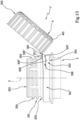
- the hinge band comprises a first hinge element and a second hinge element defined at least partly respectively in the first end zone 305a and in the second end zone 305b of the joining portion 305 and the deformation affects only the first hinge element and the second hinge element but not the connecting bands 306, 307, which therefore remain substantially undeformed and do not twist in the open condition, as illustrated in Figure 13 .
- the method for making the cap 1' of Figures 12 and 13 is also similar to that described for the cap 1 with reference to Figures 1 to 11 , except that the step of cutting the incision line 7" comprises the step of cutting the central stretch 701", the first lateral stretch 702′′′ and the second lateral stretch 703′′′ in such a way that they are continuous, and also aligned, if they lie on the same plane.
- the caps 1, 1' described above are made of plastic material, for example polypropylene (PP) or polyethylene (PE).
- PP polypropylene
- PE polyethylene
- PE polyethylene
- HDPE high-density polyethylene
- HDPE high-density polyethylene
- the material may be in the form of a homopolymer, or heterophasic copolymer, or statistical copolymer.
- the fluidity index of the PP may vary from 2 to 20 g, under the following measurement conditions: 10 minutes, 230°C, 2.16 kg.
Landscapes
- Engineering & Computer Science (AREA)
- Mechanical Engineering (AREA)
- Life Sciences & Earth Sciences (AREA)
- Forests & Forestry (AREA)
- Closures For Containers (AREA)
Claims (22)
- Un capuchon de fermeture (1) pour un contenant (2), comprenant une paroi latérale (3) s'étendant autour d'un axe (Z) et une paroi transversale (4) positionnée au niveau d'une extrémité de la paroi latérale (3), une ligne de séparation (5) étant prévue sur la paroi latérale (3) pour définir:
une bague de retenue (301), qui est configurée pour rester ancrée à un col (201) du contenant (2); un élément de fermeture (302) pouvant être assujetti de façon amovible avec le col (201), de manière à ouvrir ou fermer le contenant (2); la ligne de séparation (5) s'étendant autour de l'axe (Z) et étant circonférentiellement interrompue pour laisser unis la bague de retenue (301) et l'élément de fermeture (302); dans lequel la bague de retenue (301) comprend:- une portion de retenue (303), qui est configurée pour s'assujettir intérieurement avec une bague de blocage (202) du col (201) et s'étend jusqu'à un bord libre (304) de la bague de retenue (301),- une portion de jonction (305) où la bague de retenue (301) est jointe à l'élément de fermeture (302);- une première bande de raccordement (306), qui s'étend à partir d'une première zone d'extrémité (305a) de la portion de jonction (305) jusqu'à la portion de retenue (303), et une deuxième bande de raccordement (307), qui s'étend à partir d'une deuxième zone d'extrémité (305b) de la portion de jonction (305) jusqu'à la portion de retenue (303), la deuxième zone d'extrémité (305b) étant positionnée circonférentiellement du côté opposé à la première zone d'extrémité (305a);- une languette (308), interposée entre la première bande de raccordement (306) et la deuxième bande de raccordement (307), la languette se projetant par rapport à la première zone d'extrémité (305a) et par rapport à la deuxième zone d'extrémité (305b) vers le bord libre (304) de manière à ce que, lorsque l'élément de fermeture (302) est dans une condition ouverte et que les bandes de raccordement (306, 307) maintiennent l'élément de fermeture (302) raccordé à la bague de retenue (301), la languette (308) puisse reposer sur le col (201), caractérisé en ce que les bandes de raccordement (306; 307) et la languette (308) sont réalisées au moyen d'une ligne d'incision (7) qui s'étend entre la ligne de séparation (5) et le bord libre (304) de la bague de retenue (301), dans lequel la ligne d'incision (7) comprend un tronçon central (701) qui est interposé entre un premier tronçon latéral (702) et un deuxième tronçon latéral (703) de la ligne d'incision (7), dans lequel la ligne d'incision (7) est réalisée par des incisions passant à travers toute une épaisseur (S) de la paroi latérale (3). - Le capuchon selon la revendication 1, dans lequel la languette (308) comprend une paire de bords latéraux (311) et un bord de fond (309), le bord de fond (309) étant transversal à l'axe (Z) dans la condition fermée.
- Le capuchon selon la revendication 2, dans lequel sur la paroi latérale (3) il y a deux lignes de coupe (6) qui définissent les bords latéraux (311) respectifs de la languette (308), dans lequel les lignes de coupe (6) sont réalisées au moyen de coupes passant à travers toute une épaisseur de la paroi latérale (3).
- Le capuchon selon la revendication 3, dans lequel les bords latéraux (311) ont des hauteurs égales, sont parallèles entre eux, parallèles à l'axe (Z) et sont transversaux au bord de fond (309) de la languette (308), les lignes de coupe (6) s'étendant parallèlement à l'axe (Z), la languette (308) ayant une forme rectangulaire; ou dans lequel les bords latéraux (311) sont inclinées, ou incurvés, par rapport au bord de fond (309) de la languette (308), la languette (308) ayant une forme trapézoïdale ou rectangulaire avec des coins arrondis.
- Le capuchon selon l'une quelconque des revendications précédentes, dans lequel la languette (308) comprend une paire de bords latéraux (311) et un bord de fond (309), le bord de fond (309) étant transversal à l'axe (Z) dans la condition fermée et dans lequel la languette (308) comprend une partie extérieure (308a), qui dépasse par rapport à la première zone d'extrémité (305a) et à la deuxième zone d'extrémité (305b), et dans lequel la languette comprend en outre une partie intérieure (308b), réalisée au moins dans la portion de jonction (305), qui est interposée entre la première bande de raccordement (306) et la deuxième bande de raccordement (307) et est séparée de cette dernière par des tronçons respectifs des bords latéraux (311), et dans lequel sur la paroi latérale (3) il y a deux lignes de coupe (6) qui définissent les bords latéraux (311) respectifs de la languette (308), dans lequel les lignes de coupe (6) sont réalisées au moyen de coupes passant à travers toute une épaisseur de la paroi latérale (3), les lignes de coupe (6) s'étendant au moins à l'intérieur de la portion de jonction (305) pour définir la partie intérieure (308b) de la languette (308).
- Le capuchon selon la revendication 5, dans lequel la languette (308) comprend une partie supplémentaire réalisée dans l'élément de fermeture (302) et séparée de ce dernier par d'autres tronçons respectifs des bords latéraux (311) et dans lequel les lignes de coupe (6) s'étendent au-delà de la portion de jonction (305) et à l'intérieur de l'élément de fermeture (302) pour définir la partie supplémentaire de la languette (308).
- Le capuchon selon l'une quelconque des revendications précédentes, dans lequel le premier tronçon latéral (702) et le deuxième tronçon latéral (703) sont alignés l'un par rapport à l'autre et transversaux à l'axe Z et s'étendent dans un premier plan parallèle à un plan de séparation contenant la ligne de séparation (5), le premier tronçon latéral (702) et le deuxième tronçon latéral (703) définissant, respectivement, un premier bord inférieur libre (306') et un deuxième bord inférieur libre (307') de la première bande de raccordement (306) et de la deuxième bande de raccordement (307) et/ou dans lequel la première bande de raccordement (306) est définie entre un premier tronçon d'extrémité de la ligne de séparation (5) et le premier tronçon latéral (702) de la ligne d'incision (7); et dans lequel la deuxième bande de raccordement (307) est formée entre un deuxième tronçon d'extrémité de la ligne de séparation (5) et le deuxième tronçon latéral (703) de la ligne d'incision (7).
- Le capuchon selon la revendication 7, dans lequel la languette (308) comprend une paire de bords latéraux (311) et un bord de fond (309), le bord de fond (309) étant transversal à l'axe (Z) dans la condition fermée et dans lequel sur la paroi latérale (3) il y a deux lignes de coupe (6) qui définissent les bords latéraux (311) respectifs de la languette (308), dans lequel les lignes de coupe (6) sont réalisées au moyen de coupes passant à travers toute une épaisseur de la paroi latérale (3), le premier tronçon latéral (702) et le deuxième tronçon latéral (703) s'étendant jusqu'aux lignes de coupe (6).
- Le capuchon selon l'une quelconque des revendications précédentes, dans lequel chaque tronçon latéral (702, 703) de la ligne d'incision (7), c'est-à-dire, à la fois le premier tronçon latéral (702) et le deuxième tronçon latéral (703) , a une extension angulaire autour de l'axe (Z) comprise entre 20° et 110°, de préférence entre 30° et 70°, de façon encore plus préférée entre 50° et 60°.
- Le capuchon selon l'une quelconque des revendications précédentes, dans lequel le premier tronçon latéral (702) et le deuxième tronçon latéral (703) sont alignés l'un par rapport à l'autre et transversaux à l'axe Z et s'étendent dans un premier plan parallèle à un plan de séparation contenant la ligne de séparation (5), et dans lequel le tronçon central (701) s'étend dans un deuxième plan parallèle au plan de séparation et est interposé entre le premier plan et le bord libre (304) de la bague de retenue (301), et dans lequel la languette (308) comprend une paire de bords latéraux (311) et un bord de fond (309), le bord de fond (309) étant transversal à l'axe (Z) dans la condition fermée, le tronçon central (701) définissant le bord de fond (309) de la languette (308).
- Le capuchon selon l'une quelconque des revendications précédentes, dans lequel le tronçon central (701) a une extension angulaire autour de l'axe (Z) comprise entre 10° et 120°, de préférence entre 15° et 70°, de façon plus préférée entre 20° et 50°, de façon toujours plus préférée entre 30° et 40°, de façon encore plus préférée égale à 25°.
- Le capuchon selon l'une quelconque des revendications précédentes, dans lequel la portion de jonction (305) a une extension angulaire autour de l'axe (Z) comprise entre 10° et 120°, de préférence entre 30° et 110°, de façon encore plus préférée entre 20° et 40°.
- Le capuchon selon l'une quelconque des revendications précédentes, dans lequel la portion de jonction (305) a une ligne médiane, une ligne médiane de la languette (308) coïncidant avec la ligne médiane de la portion de jonction (305), la première bande de raccordement (306) et la deuxième bande de raccordement (307) étant positionnées symétriquement par rapport à un plan contenant l'axe (Z) et la ligne médiane de la portion de jonction (305).
- Le capuchon selon l'une quelconque des revendications précédentes, dans lequel, lorsque l'élément de fermeture (302) est dans une condition ouverte et que les bandes de raccordement (306, 307) maintiennent l'élément de fermeture (302) raccordé à la bague de retenue (301), la portion de jonction (305) définit une bande charnière autour de laquelle l'élément de fermeture (302) peut tourner par rapport au col (201), en se déformant, et optionnellement dans lequel la bande charnière comprend un premier élément charnière et un deuxième élément charnière définis au moins partiellement, respectivement, dans la première zone d'extrémité (305a) et dans la deuxième zone d'extrémité (305b) de la portion de jonction (305), la déformation concernant exclusivement le premier élément charnière et le deuxième élément charnière mais pas les bandes de raccordement (306, 307).
- Le capuchon selon l'une quelconque des revendications de 2 à 14, dans lequel la languette (308) est raccordée à la paroi latérale (3) par une ligne charnière (310), autour de laquelle la languette (308) peut fléchir, qui est transversale à l'axe (Z), et dans lequel les bords latéraux (311) de la languette (308) s'étendent à partir de la ligne charnière (310).
- Un procédé de fabrication d'un capuchon (1), comprenant les étapes suivantes: fournir une paroi latérale (3) d'un corps concave (8) s'étendant autour d'un axe (Z) et une paroi transversale (4) positionnée au niveau d'une extrémité de la paroi latérale (3), couper une ligne de séparation (5) sur la paroi latérale (3) qui s'étend autour de l'axe (Z) pour définir: une bague de retenue (301), configurée pour rester ancrée à un col (201) du contenant (2) qui s'étend jusqu'à un bord libre (304); un élément de fermeture (302) pouvant être assujetti de façon amovible avec le col (201), de manière à ouvrir ou fermer le contenant (2) ; dans lequel l'étape de coupe de la ligne de séparation (5) comprend une interruption de la coupe entre une première extrémité (501) et une deuxième extrémité (502), pour laisser unis la bague de retenue (301) et l'élément de fermeture (302); le procédé comprenant également l'étape consistant à: joindre la bague de retenue (301) et l'élément de fermeture (302) au moyen d'une portion de jonction (305); définir dans la bague de retenue (301) une première bande de raccordement (306), qui s'étend à partir d'une première zone d'extrémité (305a) de la portion de jonction (305), et une deuxième bande de raccordement (307), qui s'étend à partir d'une deuxième zone d'extrémité (305b) de la portion de jonction (305), la deuxième zone d'extrémité (305b) étant positionnée circonférentiellement du côté opposé à la première zone d'extrémité (305a); interposer une languette (308; 308") entre la première bande de raccordement (306) et la deuxième bande de raccordement (307), de manière à ce que, lorsque le contenant (2) est ouvert et que les bandes de raccordement (306, 307) maintiennent l'élément de fermeture (302) raccordé à la bague de retenue (301), la languette (308) puisse reposer sur le col (201), caractérisé en ce que le procédé comprend en outre l'étape de coupe d'une ligne d'incision (7) réalisée par des incisions passant à travers toute une épaisseur (S) de la paroi latérale (3); ladite étape de coupe de la ligne d'incision (7) comprenant l'étape consistant à réaliser un tronçon central (701) interposé entre un premier tronçon latéral (702) et un deuxième tronçon latéral (703) de la ligne d'incision (7).
- Le procédé selon la revendication 16, et comprenant l'étape de coupe de la ligne d'incision (7) s'étendant entre la ligne de séparation (5) et le bord libre (304) de la bague de retenue (301), qui comprend l'étape consistant à réaliser le premier tronçon latéral (702) et le deuxième tronçon latéral (703) transversalement à l'axe (Z) dans un premier plan parallèle à un plan de séparation contenant la ligne de séparation (5), pour définir un premier bord inférieur libre (306') de la première bande de raccordement (306) et un deuxième bord inférieur libre (307') de la deuxième bande de raccordement (307); réaliser le tronçon central (701) dans un deuxième plan parallèle au plan de séparation et interposé entre le premier plan de séparation et le bord libre (304) de la bague de retenue (301), pour définir un bord de fond (309) de la languette (308); dans lequel l'étape consistant à réaliser le premier tronçon latéral (702), le deuxième tronçon latéral (703) et le tronçon central (701) de la ligne d'incision (7) comprend l'utilisation d'outils de coupe (901a) qui sont positionnés transversalement à l'axe (Z).
- Le procédé selon la revendication 16 ou 17, et comprenant l'étape consistant à réaliser deux lignes de coupe (6) parallèles à l'axe (Z) pour obtenir des bords latéraux (311) respectifs de la languette (308), parallèles entre eux et parallèles à l'axe (Z), dans lequel l'étape consistant à réaliser les lignes de coupe (6) comprend l'utilisation d'outils de coupe (901b) positionnés parallèlement à l'axe (Z).
- Le procédé selon la revendication 18, quand dépendant de la revendication 17, et comprenant l'étape consistant à utiliser en succession d'abord les outils de coupe (901a) positionnés transversalement à l'axe (Z) puis les outils de coupe (901b) positionnés parallèlement à l'axe (Z), ou inversement; ou comprenant l'étape consistant à fournir les outils de coupe (901a) positionnés transversalement à l'axe (Z) et/ou les outils de coupe (901b) positionnés parallèlement à l'axe (Z) de manière à effectuer angulairement en succession un premier tronçon latéral (702) de la ligne d'incision (7), une première ligne de coupe (6) des lignes de coupe, le tronçon central (701) de la ligne d'incision (7), une deuxième ligne de coupe (6) des lignes de coupe, le deuxième tronçon latéral (703) de la ligne d'incision (7).
- Le procédé selon la revendication 18, ou 19, quand dépendant de la revendication 17, et comprenant l'étape de coupe de la ligne de séparation (5) et de la ligne d'incision (7) en utilisant des outils de coupe qui ont un bord de coupe interrompu pour définir, respectivement, une pluralité de ponts rupturables (503) le long de la ligne de séparation (5) et optionnellement pour définir une pluralité d'éléments rupturables (704) le long de la ligne d'incision (7); ou comprenant l'étape de coupe de la ligne de séparation (5) et de la ligne de d'incision (7) en utilisant des outils de coupe (901a) ayant un bord de coupe plat.
- Le procédé selon l'une quelconque des revendications de 18 à 20, quand dépendant de la revendication 17, et comprenant l'étape de formation du corps concave (8) et de coupe en utilisant des outils de coupe (901), par l'extérieur du corps concave (8), ou par l'intérieur du corps concave (8), de la ligne de séparation (5), la ligne d'incision (7) et les lignes de coupe (6) en faisant tourner le corps concave (8) et en maintenant les outils de coupe (901) immobiles ou en maintenant le corps concave (8) immobile et en faisant tourner les outils de coupe (902) autour de celui-ci, pour obtenir le capuchon (1).
- Le procédé selon la revendication 21, et comprenant l'étape consistant à pousser le corps concave (8) en utilisant une broche (904) équipée d'un anneau de contact (905) réalisé dans un matériau polymère de manière à ce qu'une première portion de la paroi latérale (3) vienne pousser contre une première portion (902a) d'une surface extérieure dotée d'outils de coupe (901a, 901b) et à ce qu'une deuxième portion de la paroi latérale (3), dotée d'une pluralité de moletages (312), assujettisse une pluralité respective de moletages présents dans une deuxième portion (902b) de la surface extérieure, conformés de façon complémentaire aux moletages (312) de la paroi latérale (3); et optionnellement comprenant l'étape consistant à faire tourner la broche (904) de manière à ce que le corps concave (8) roule sur la surface extérieure entraîné par la mise en prise entre la deuxième portion de la paroi latérale (3) avec la deuxième portion (902b) de la surface extérieure.
Applications Claiming Priority (5)
| Application Number | Priority Date | Filing Date | Title |
|---|---|---|---|
| IT102019000012585A IT201900012585A1 (it) | 2019-07-22 | 2019-07-22 | Tappo di chiusura per un contenitore e relativo metodo di produzione. |
| IT201900012534 | 2019-07-22 | ||
| IT102020000006496A IT202000006496A1 (it) | 2020-03-27 | 2020-03-27 | Combinazione di un tappo per un contenitore e di un collo del contenitore. |
| PCT/IB2020/056686 WO2021014290A1 (fr) | 2019-07-22 | 2020-07-16 | Capuchon pour récipient, combinaison d'un capuchon et d'un col du récipient et son procédé de production |
| EP20750741.9A EP3877281B1 (fr) | 2019-07-22 | 2020-07-16 | Capuchon pour récipient, combinaison d'un capuchon et d'un col du récipient et son procédé de production |
Related Parent Applications (2)
| Application Number | Title | Priority Date | Filing Date |
|---|---|---|---|
| EP20750741.9A Division-Into EP3877281B1 (fr) | 2019-07-22 | 2020-07-16 | Capuchon pour récipient, combinaison d'un capuchon et d'un col du récipient et son procédé de production |
| EP20750741.9A Division EP3877281B1 (fr) | 2019-07-22 | 2020-07-16 | Capuchon pour récipient, combinaison d'un capuchon et d'un col du récipient et son procédé de production |
Publications (2)
| Publication Number | Publication Date |
|---|---|
| EP4046933A1 EP4046933A1 (fr) | 2022-08-24 |
| EP4046933B1 true EP4046933B1 (fr) | 2024-06-12 |
Family
ID=71944159
Family Applications (2)
| Application Number | Title | Priority Date | Filing Date |
|---|---|---|---|
| EP20750741.9A Active EP3877281B1 (fr) | 2019-07-22 | 2020-07-16 | Capuchon pour récipient, combinaison d'un capuchon et d'un col du récipient et son procédé de production |
| EP22164282.0A Active EP4046933B1 (fr) | 2019-07-22 | 2020-07-16 | Capuchon de contenant et son procédé de production |
Family Applications Before (1)
| Application Number | Title | Priority Date | Filing Date |
|---|---|---|---|
| EP20750741.9A Active EP3877281B1 (fr) | 2019-07-22 | 2020-07-16 | Capuchon pour récipient, combinaison d'un capuchon et d'un col du récipient et son procédé de production |
Country Status (9)
| Country | Link |
|---|---|
| US (1) | US11697534B2 (fr) |
| EP (2) | EP3877281B1 (fr) |
| CN (2) | CN113316546B (fr) |
| ES (2) | ES2935475T3 (fr) |
| HU (2) | HUE061005T2 (fr) |
| MX (2) | MX2021007984A (fr) |
| RU (1) | RU2765791C1 (fr) |
| WO (1) | WO2021014290A1 (fr) |
| ZA (1) | ZA202103869B (fr) |
Families Citing this family (24)
| Publication number | Priority date | Publication date | Assignee | Title |
|---|---|---|---|---|
| MX2021011789A (es) * | 2019-04-15 | 2021-10-26 | Alpla Werke Alwin Lehner Gmbh & Co Kg | Cierre de recipiente. |
| IT202000006496A1 (it) | 2020-03-27 | 2021-09-27 | Sacmi | Combinazione di un tappo per un contenitore e di un collo del contenitore. |
| WO2021046413A1 (fr) * | 2019-09-06 | 2021-03-11 | Silgan White Cap LLC | Moyen de fermeture à charnière captif |
| MX2022003784A (es) * | 2019-09-30 | 2022-04-25 | Berry Global Inc | Cierre retenible. |
| EP4282774A3 (fr) * | 2019-11-29 | 2024-03-06 | SIG Services AG | Élément verseur refermable pour emballage composite carton/plastique doté d'une bague d'ancrage pour fixer solidement un bouchon à vis |
| JP2022018869A (ja) * | 2020-07-16 | 2022-01-27 | キヤノン株式会社 | 液体収容容器 |
| IT202000019939A1 (it) * | 2020-08-11 | 2022-02-11 | Guala Pack Spa | Chiusura per una cannuccia di un imballo a pareti sottili |
| EP4011801B1 (fr) * | 2020-12-11 | 2023-04-05 | SACMI Cooperativa Meccanici Imola Società Cooperativa | Fermeture de récipient |
| US12515859B2 (en) * | 2021-01-12 | 2026-01-06 | Sacmi Cooperativa Meccanici Imola Societa' Cooperativa | Cap for container |
| CN116723988B (zh) * | 2021-01-27 | 2025-09-12 | 株式会社益力多本社 | 合成树脂盖 |
| US12351373B2 (en) * | 2021-05-12 | 2025-07-08 | Paul Bradley Forrest | Releasable container cap |
| CH718712A1 (de) * | 2021-06-07 | 2022-12-15 | Alpla Werke Alwin Lehner Gmbh & Co Kg | Unverlierbare Verschlusskappe. |
| IT202100017933A1 (it) * | 2021-07-07 | 2023-01-07 | Sacmi | Coltello per incidere capsule |
| TWI909064B (zh) * | 2021-07-21 | 2025-12-21 | 義大利商沙克米機械商業合作艾莫勒精簡公司 | 用於切割容器之封閉件之設備及方法 |
| IT202100019310A1 (it) * | 2021-07-21 | 2023-01-21 | Sacmi | Apparato e metodo per tagliare chiusure per contenitori |
| IT202200008678A1 (it) * | 2022-04-29 | 2023-10-29 | Sacmi | Apparato e metodo per tagliare chiusure per contenitori |
| DE102021125520A1 (de) * | 2021-10-01 | 2023-04-06 | Bericap Holding Gmbh | Verschlussvorrichtung mit Stützring |
| IT202100028385A1 (it) * | 2021-11-08 | 2023-05-08 | Sacmi Cooperativa Mecc Imola Societa’ Cooperativa | Tappo di chiusura per un contenitore. |
| US20250058923A1 (en) * | 2021-12-30 | 2025-02-20 | Tetra Laval Holdings & Finance S.A. | Neck and cap for a food package |
| AU2023219700A1 (en) * | 2022-02-11 | 2024-07-18 | Silgan White Cap LLC | Tethered, hinged closure with modified primary slit |
| WO2023167609A1 (fr) * | 2022-03-03 | 2023-09-07 | МАКСИМ Николаевич МИРОНОВ | Couvercle pour bouteille avec support |
| WO2023167610A1 (fr) * | 2022-03-03 | 2023-09-07 | МАКСИМ Николаевич МИРОНОВ | Couvercle pour bouteille avec support |
| IT202400002872A1 (it) * | 2024-02-12 | 2025-08-12 | Sacmi | Tappo di chiusura per un contenitore |
| EP4650296A1 (fr) * | 2024-05-16 | 2025-11-19 | UAB "Plastikse" | Bouchon captif en plastique pour un récipient et procédé de production |
Citations (1)
| Publication number | Priority date | Publication date | Assignee | Title |
|---|---|---|---|---|
| US10654625B2 (en) * | 2018-10-12 | 2020-05-19 | Closure Systems International Inc. | Twist and flip lock closure |
Family Cites Families (29)
| Publication number | Priority date | Publication date | Assignee | Title |
|---|---|---|---|---|
| FR2499519A1 (fr) * | 1981-02-11 | 1982-08-13 | Grussen Jean | Capsule de bouchage a vis avec anneau d'inviolabilite |
| US5246125A (en) | 1992-05-04 | 1993-09-21 | Sunbeam Plastics Corporation | Tamper indicating closure with attached tamper indicating band |
| US5360126A (en) | 1992-12-21 | 1994-11-01 | Zapata Industries, Inc. | Tamper-evident plastic closure with 2-tier bridge arrangement |
| FR2785264B1 (fr) * | 1998-10-29 | 2001-01-05 | Crown Cork & Seal Tech Corp | Dispositif de bouchage |
| AUPP792998A0 (en) * | 1998-12-24 | 1999-01-28 | Amcor Packaging (Australia) Pty Ltd | Closure |
| US6520370B2 (en) * | 2001-01-11 | 2003-02-18 | Paradigm Packaging, Inc. | Product dispensing closure with lid support |
| US7513377B1 (en) * | 2002-10-03 | 2009-04-07 | Rexam Closures And Containers Inc. | Folding finger tamper-indicating band arrester |
| EP1786695A4 (fr) * | 2004-09-07 | 2008-12-31 | Ryn Marcel Van | Bouchon indicateur d'ouverture |
| ES2262450B1 (es) * | 2006-05-18 | 2007-09-16 | Seaplast, S.A. | "tapon con tapa abatible para botellas y similares dotado de un sistema automatico de apertura de la tapa que comprende un pulsador mejorado". |
| FR2913002B1 (fr) * | 2007-02-28 | 2009-04-10 | Tetra Laval Holdings & Finance | Bouchon articule en matiere plastique |
| CA2702174A1 (fr) | 2007-10-10 | 2009-04-16 | Best Easy Cap Co., Ltd. | Contenant pourvu d'un bouchon anti-perte et anti-rotation a vide |
| RU2478542C2 (ru) | 2008-07-08 | 2013-04-10 | Джапан Краун Корк Ко., Лтд. | Выполненная из синтетической смолы крышка контейнера |
| US8695822B2 (en) | 2010-01-25 | 2014-04-15 | Si-Joong Kwon | Container for preventing loss of stopper and idle rotation thereof |
| KR100981240B1 (ko) * | 2010-03-23 | 2010-09-10 | 권시중 | 공회전 방지 버팀대가 구비된 포장용기 마개 |
| US9108774B2 (en) * | 2010-01-28 | 2015-08-18 | Si Joong Kwon | Stopper for packaging container |
| JP5600461B2 (ja) | 2010-03-31 | 2014-10-01 | 日本クロージャー株式会社 | 合成樹脂製容器蓋 |
| ES2527145T3 (es) * | 2010-04-01 | 2015-01-20 | Tetra Laval Holdings & Finance S.A. | Un cierre para un recipiente |
| JP5086465B2 (ja) * | 2011-01-14 | 2012-11-28 | 相伍 林 | 容器用キャップ |
| JP5697505B2 (ja) | 2011-03-24 | 2015-04-08 | 日本クロージャー株式会社 | 合成樹脂製容器蓋 |
| JP5580240B2 (ja) * | 2011-03-31 | 2014-08-27 | 能美防災株式会社 | 自動弁装置およびそれに用いられる圧力調整弁 |
| EP2631194B1 (fr) * | 2012-02-22 | 2017-02-01 | Tetra Laval Holdings & Finance S.A. | Fermeture pour un récipient de produit versable |
| JP5948181B2 (ja) | 2012-08-03 | 2016-07-06 | 日本クロージャー株式会社 | 合成樹脂製容器蓋 |
| TWI589498B (zh) | 2015-04-02 | 2017-07-01 | 邁可約瑟夫 麥奎爾 | 容器用之蓋子 |
| ITUB20160971A1 (it) * | 2016-02-23 | 2017-08-23 | Sacmi | Elemento di chiusura per un contenitore. |
| KR102195928B1 (ko) * | 2017-03-07 | 2020-12-28 | 성보연 | 개방상태 유지기능을 갖는 용기마개 |
| WO2020014077A1 (fr) * | 2018-07-11 | 2020-01-16 | Closure Systems International Inc. | Fermeture à torsion et à retournement |
| RS63969B1 (sr) | 2018-09-04 | 2023-03-31 | Thiscap Inc | Zatvarač za posudu |
| CA3111616A1 (fr) | 2018-11-04 | 2020-05-07 | Novembal Usa Inc. | Bouchon a vis en plastique attache |
| PL3995410T3 (pl) | 2018-11-16 | 2024-06-24 | Bericap Holding Gmbh | Kombinacja szyjki pojemnika i niegubiącego się zamknięcia o stabilizowanym kącie otwarcia |
-
2020
- 2020-07-16 ES ES20750741T patent/ES2935475T3/es active Active
- 2020-07-16 EP EP20750741.9A patent/EP3877281B1/fr active Active
- 2020-07-16 US US17/419,139 patent/US11697534B2/en active Active
- 2020-07-16 CN CN202080007740.1A patent/CN113316546B/zh active Active
- 2020-07-16 RU RU2021118762A patent/RU2765791C1/ru active
- 2020-07-16 WO PCT/IB2020/056686 patent/WO2021014290A1/fr not_active Ceased
- 2020-07-16 MX MX2021007984A patent/MX2021007984A/es unknown
- 2020-07-16 EP EP22164282.0A patent/EP4046933B1/fr active Active
- 2020-07-16 HU HUE20750741A patent/HUE061005T2/hu unknown
- 2020-07-16 ES ES22164282T patent/ES2986139T3/es active Active
- 2020-07-16 HU HUE22164282A patent/HUE068232T2/hu unknown
- 2020-07-16 CN CN202310961194.0A patent/CN116812347B/zh active Active
-
2021
- 2021-06-04 ZA ZA2021/03869A patent/ZA202103869B/en unknown
- 2021-06-29 MX MX2024012890A patent/MX2024012890A/es unknown
Patent Citations (1)
| Publication number | Priority date | Publication date | Assignee | Title |
|---|---|---|---|---|
| US10654625B2 (en) * | 2018-10-12 | 2020-05-19 | Closure Systems International Inc. | Twist and flip lock closure |
Also Published As
| Publication number | Publication date |
|---|---|
| EP3877281B1 (fr) | 2022-11-02 |
| ES2986139T3 (es) | 2024-11-08 |
| HUE061005T2 (hu) | 2023-04-28 |
| MX2021007984A (es) | 2021-08-16 |
| US11697534B2 (en) | 2023-07-11 |
| CN116812347B (zh) | 2026-03-24 |
| CN113316546A (zh) | 2021-08-27 |
| ZA202103869B (en) | 2023-01-25 |
| EP3877281A1 (fr) | 2021-09-15 |
| BR112021013048A2 (pt) | 2022-04-19 |
| WO2021014290A1 (fr) | 2021-01-28 |
| RU2765791C1 (ru) | 2022-02-03 |
| CN113316546B (zh) | 2023-08-18 |
| US20220204228A1 (en) | 2022-06-30 |
| HUE068232T2 (hu) | 2024-12-28 |
| EP4046933A1 (fr) | 2022-08-24 |
| ES2935475T3 (es) | 2023-03-07 |
| MX2024012890A (es) | 2024-11-08 |
| CN116812347A (zh) | 2023-09-29 |
Similar Documents
| Publication | Publication Date | Title |
|---|---|---|
| EP3877281B1 (fr) | Capuchon pour récipient, combinaison d'un capuchon et d'un col du récipient et son procédé de production | |
| EP3892567B1 (fr) | Combinaison d'un capuchon pour un récipient et d'un col du récipient | |
| EP3953264B1 (fr) | Bouchon de fermeture pour récipient et son procédé de production | |
| EP4001157B1 (fr) | Bouchon de fermeture d'un récipient, combinaison d'un bouchon et d'un goulot | |
| EP3976487B1 (fr) | Capuchon pour un récipient et combinaison d'un capuchon et d'un col de récipient | |
| EP4282775B1 (fr) | Un bouchon pour fermer un récipient | |
| EP3959149B1 (fr) | Bouchon de fermeture d'un contenant et procédé de fabrication du bouchon | |
| EP4011801B1 (fr) | Fermeture de récipient | |
| US20230322457A1 (en) | Method for producing a cap for a container-- | |
| US12497224B2 (en) | Cap for container | |
| EP4277858B1 (fr) | Capuchon pour récipient | |
| EP4461669B1 (fr) | Capuchon pour récipient |
Legal Events
| Date | Code | Title | Description |
|---|---|---|---|
| PUAI | Public reference made under article 153(3) epc to a published international application that has entered the european phase |
Free format text: ORIGINAL CODE: 0009012 |
|
| STAA | Information on the status of an ep patent application or granted ep patent |
Free format text: STATUS: THE APPLICATION HAS BEEN PUBLISHED |
|
| AC | Divisional application: reference to earlier application |
Ref document number: 3877281 Country of ref document: EP Kind code of ref document: P |
|
| AK | Designated contracting states |
Kind code of ref document: A1 Designated state(s): AL AT BE BG CH CY CZ DE DK EE ES FI FR GB GR HR HU IE IS IT LI LT LU LV MC MK MT NL NO PL PT RO RS SE SI SK SM TR |
|
| STAA | Information on the status of an ep patent application or granted ep patent |
Free format text: STATUS: REQUEST FOR EXAMINATION WAS MADE |
|
| 17P | Request for examination filed |
Effective date: 20230222 |
|
| RBV | Designated contracting states (corrected) |
Designated state(s): AL AT BE BG CH CY CZ DE DK EE ES FI FR GB GR HR HU IE IS IT LI LT LU LV MC MK MT NL NO PL PT RO RS SE SI SK SM TR |
|
| GRAP | Despatch of communication of intention to grant a patent |
Free format text: ORIGINAL CODE: EPIDOSNIGR1 |
|
| STAA | Information on the status of an ep patent application or granted ep patent |
Free format text: STATUS: GRANT OF PATENT IS INTENDED |
|
| RIC1 | Information provided on ipc code assigned before grant |
Ipc: B26D 1/00 20060101ALI20230418BHEP Ipc: B26F 1/18 20060101ALI20230418BHEP Ipc: B26D 7/06 20060101ALI20230418BHEP Ipc: B65D 55/16 20060101ALI20230418BHEP Ipc: B65D 41/34 20060101AFI20230418BHEP |
|
| INTG | Intention to grant announced |
Effective date: 20230519 |
|
| P01 | Opt-out of the competence of the unified patent court (upc) registered |
Effective date: 20230525 |
|
| GRAJ | Information related to disapproval of communication of intention to grant by the applicant or resumption of examination proceedings by the epo deleted |
Free format text: ORIGINAL CODE: EPIDOSDIGR1 |
|
| STAA | Information on the status of an ep patent application or granted ep patent |
Free format text: STATUS: REQUEST FOR EXAMINATION WAS MADE |
|
| INTC | Intention to grant announced (deleted) | ||
| GRAP | Despatch of communication of intention to grant a patent |
Free format text: ORIGINAL CODE: EPIDOSNIGR1 |
|
| STAA | Information on the status of an ep patent application or granted ep patent |
Free format text: STATUS: GRANT OF PATENT IS INTENDED |
|
| INTG | Intention to grant announced |
Effective date: 20240105 |
|
| GRAS | Grant fee paid |
Free format text: ORIGINAL CODE: EPIDOSNIGR3 |
|
| GRAA | (expected) grant |
Free format text: ORIGINAL CODE: 0009210 |
|
| STAA | Information on the status of an ep patent application or granted ep patent |
Free format text: STATUS: THE PATENT HAS BEEN GRANTED |
|
| AC | Divisional application: reference to earlier application |
Ref document number: 3877281 Country of ref document: EP Kind code of ref document: P |
|
| AK | Designated contracting states |
Kind code of ref document: B1 Designated state(s): AL AT BE BG CH CY CZ DE DK EE ES FI FR GB GR HR HU IE IS IT LI LT LU LV MC MK MT NL NO PL PT RO RS SE SI SK SM TR |
|
| REG | Reference to a national code |
Ref country code: GB Ref legal event code: FG4D |
|
| REG | Reference to a national code |
Ref country code: CH Ref legal event code: EP |
|
| REG | Reference to a national code |
Ref country code: DE Ref legal event code: R096 Ref document number: 602020032506 Country of ref document: DE |
|
| REG | Reference to a national code |
Ref country code: IE Ref legal event code: FG4D |
|
| PG25 | Lapsed in a contracting state [announced via postgrant information from national office to epo] |
Ref country code: BG Free format text: LAPSE BECAUSE OF FAILURE TO SUBMIT A TRANSLATION OF THE DESCRIPTION OR TO PAY THE FEE WITHIN THE PRESCRIBED TIME-LIMIT Effective date: 20240612 |
|
| PG25 | Lapsed in a contracting state [announced via postgrant information from national office to epo] |
Ref country code: FI Free format text: LAPSE BECAUSE OF FAILURE TO SUBMIT A TRANSLATION OF THE DESCRIPTION OR TO PAY THE FEE WITHIN THE PRESCRIBED TIME-LIMIT Effective date: 20240612 Ref country code: HR Free format text: LAPSE BECAUSE OF FAILURE TO SUBMIT A TRANSLATION OF THE DESCRIPTION OR TO PAY THE FEE WITHIN THE PRESCRIBED TIME-LIMIT Effective date: 20240612 |
|
| REG | Reference to a national code |
Ref country code: LT Ref legal event code: MG9D |
|
| PG25 | Lapsed in a contracting state [announced via postgrant information from national office to epo] |
Ref country code: GR Free format text: LAPSE BECAUSE OF FAILURE TO SUBMIT A TRANSLATION OF THE DESCRIPTION OR TO PAY THE FEE WITHIN THE PRESCRIBED TIME-LIMIT Effective date: 20240913 |
|
| REG | Reference to a national code |
Ref country code: NL Ref legal event code: MP Effective date: 20240612 |
|
| PG25 | Lapsed in a contracting state [announced via postgrant information from national office to epo] |
Ref country code: LV Free format text: LAPSE BECAUSE OF FAILURE TO SUBMIT A TRANSLATION OF THE DESCRIPTION OR TO PAY THE FEE WITHIN THE PRESCRIBED TIME-LIMIT Effective date: 20240612 |
|
| PG25 | Lapsed in a contracting state [announced via postgrant information from national office to epo] |
Ref country code: NO Free format text: LAPSE BECAUSE OF FAILURE TO SUBMIT A TRANSLATION OF THE DESCRIPTION OR TO PAY THE FEE WITHIN THE PRESCRIBED TIME-LIMIT Effective date: 20240912 Ref country code: LV Free format text: LAPSE BECAUSE OF FAILURE TO SUBMIT A TRANSLATION OF THE DESCRIPTION OR TO PAY THE FEE WITHIN THE PRESCRIBED TIME-LIMIT Effective date: 20240612 Ref country code: HR Free format text: LAPSE BECAUSE OF FAILURE TO SUBMIT A TRANSLATION OF THE DESCRIPTION OR TO PAY THE FEE WITHIN THE PRESCRIBED TIME-LIMIT Effective date: 20240612 Ref country code: GR Free format text: LAPSE BECAUSE OF FAILURE TO SUBMIT A TRANSLATION OF THE DESCRIPTION OR TO PAY THE FEE WITHIN THE PRESCRIBED TIME-LIMIT Effective date: 20240913 Ref country code: FI Free format text: LAPSE BECAUSE OF FAILURE TO SUBMIT A TRANSLATION OF THE DESCRIPTION OR TO PAY THE FEE WITHIN THE PRESCRIBED TIME-LIMIT Effective date: 20240612 Ref country code: BG Free format text: LAPSE BECAUSE OF FAILURE TO SUBMIT A TRANSLATION OF THE DESCRIPTION OR TO PAY THE FEE WITHIN THE PRESCRIBED TIME-LIMIT Effective date: 20240612 Ref country code: RS Free format text: LAPSE BECAUSE OF FAILURE TO SUBMIT A TRANSLATION OF THE DESCRIPTION OR TO PAY THE FEE WITHIN THE PRESCRIBED TIME-LIMIT Effective date: 20240912 |
|
| REG | Reference to a national code |
Ref country code: ES Ref legal event code: FG2A Ref document number: 2986139 Country of ref document: ES Kind code of ref document: T3 Effective date: 20241108 |
|
| PG25 | Lapsed in a contracting state [announced via postgrant information from national office to epo] |
Ref country code: NL Free format text: LAPSE BECAUSE OF FAILURE TO SUBMIT A TRANSLATION OF THE DESCRIPTION OR TO PAY THE FEE WITHIN THE PRESCRIBED TIME-LIMIT Effective date: 20240612 |
|
| PG25 | Lapsed in a contracting state [announced via postgrant information from national office to epo] |
Ref country code: NL Free format text: LAPSE BECAUSE OF FAILURE TO SUBMIT A TRANSLATION OF THE DESCRIPTION OR TO PAY THE FEE WITHIN THE PRESCRIBED TIME-LIMIT Effective date: 20240612 |
|
| PG25 | Lapsed in a contracting state [announced via postgrant information from national office to epo] |
Ref country code: PT Free format text: LAPSE BECAUSE OF FAILURE TO SUBMIT A TRANSLATION OF THE DESCRIPTION OR TO PAY THE FEE WITHIN THE PRESCRIBED TIME-LIMIT Effective date: 20241014 |
|
| REG | Reference to a national code |
Ref country code: HU Ref legal event code: AG4A Ref document number: E068232 Country of ref document: HU |
|
| PG25 | Lapsed in a contracting state [announced via postgrant information from national office to epo] |
Ref country code: PT Free format text: LAPSE BECAUSE OF FAILURE TO SUBMIT A TRANSLATION OF THE DESCRIPTION OR TO PAY THE FEE WITHIN THE PRESCRIBED TIME-LIMIT Effective date: 20241014 |
|
| PG25 | Lapsed in a contracting state [announced via postgrant information from national office to epo] |
Ref country code: PL Free format text: LAPSE BECAUSE OF FAILURE TO SUBMIT A TRANSLATION OF THE DESCRIPTION OR TO PAY THE FEE WITHIN THE PRESCRIBED TIME-LIMIT Effective date: 20240612 |
|
| PG25 | Lapsed in a contracting state [announced via postgrant information from national office to epo] |
Ref country code: EE Free format text: LAPSE BECAUSE OF FAILURE TO SUBMIT A TRANSLATION OF THE DESCRIPTION OR TO PAY THE FEE WITHIN THE PRESCRIBED TIME-LIMIT Effective date: 20240612 |
|
| PG25 | Lapsed in a contracting state [announced via postgrant information from national office to epo] |
Ref country code: IS Free format text: LAPSE BECAUSE OF FAILURE TO SUBMIT A TRANSLATION OF THE DESCRIPTION OR TO PAY THE FEE WITHIN THE PRESCRIBED TIME-LIMIT Effective date: 20241012 |
|
| PG25 | Lapsed in a contracting state [announced via postgrant information from national office to epo] |
Ref country code: CZ Free format text: LAPSE BECAUSE OF FAILURE TO SUBMIT A TRANSLATION OF THE DESCRIPTION OR TO PAY THE FEE WITHIN THE PRESCRIBED TIME-LIMIT Effective date: 20240612 |
|
| PG25 | Lapsed in a contracting state [announced via postgrant information from national office to epo] |
Ref country code: SK Free format text: LAPSE BECAUSE OF FAILURE TO SUBMIT A TRANSLATION OF THE DESCRIPTION OR TO PAY THE FEE WITHIN THE PRESCRIBED TIME-LIMIT Effective date: 20240612 Ref country code: RO Free format text: LAPSE BECAUSE OF FAILURE TO SUBMIT A TRANSLATION OF THE DESCRIPTION OR TO PAY THE FEE WITHIN THE PRESCRIBED TIME-LIMIT Effective date: 20240612 |
|
| PG25 | Lapsed in a contracting state [announced via postgrant information from national office to epo] |
Ref country code: SM Free format text: LAPSE BECAUSE OF FAILURE TO SUBMIT A TRANSLATION OF THE DESCRIPTION OR TO PAY THE FEE WITHIN THE PRESCRIBED TIME-LIMIT Effective date: 20240612 |
|
| PG25 | Lapsed in a contracting state [announced via postgrant information from national office to epo] |
Ref country code: SM Free format text: LAPSE BECAUSE OF FAILURE TO SUBMIT A TRANSLATION OF THE DESCRIPTION OR TO PAY THE FEE WITHIN THE PRESCRIBED TIME-LIMIT Effective date: 20240612 Ref country code: SK Free format text: LAPSE BECAUSE OF FAILURE TO SUBMIT A TRANSLATION OF THE DESCRIPTION OR TO PAY THE FEE WITHIN THE PRESCRIBED TIME-LIMIT Effective date: 20240612 Ref country code: RO Free format text: LAPSE BECAUSE OF FAILURE TO SUBMIT A TRANSLATION OF THE DESCRIPTION OR TO PAY THE FEE WITHIN THE PRESCRIBED TIME-LIMIT Effective date: 20240612 Ref country code: PL Free format text: LAPSE BECAUSE OF FAILURE TO SUBMIT A TRANSLATION OF THE DESCRIPTION OR TO PAY THE FEE WITHIN THE PRESCRIBED TIME-LIMIT Effective date: 20240612 Ref country code: IS Free format text: LAPSE BECAUSE OF FAILURE TO SUBMIT A TRANSLATION OF THE DESCRIPTION OR TO PAY THE FEE WITHIN THE PRESCRIBED TIME-LIMIT Effective date: 20241012 Ref country code: EE Free format text: LAPSE BECAUSE OF FAILURE TO SUBMIT A TRANSLATION OF THE DESCRIPTION OR TO PAY THE FEE WITHIN THE PRESCRIBED TIME-LIMIT Effective date: 20240612 Ref country code: CZ Free format text: LAPSE BECAUSE OF FAILURE TO SUBMIT A TRANSLATION OF THE DESCRIPTION OR TO PAY THE FEE WITHIN THE PRESCRIBED TIME-LIMIT Effective date: 20240612 |
|
| REG | Reference to a national code |
Ref country code: DE Ref legal event code: R097 Ref document number: 602020032506 Country of ref document: DE |
|
| PG25 | Lapsed in a contracting state [announced via postgrant information from national office to epo] |
Ref country code: LU Free format text: LAPSE BECAUSE OF NON-PAYMENT OF DUE FEES Effective date: 20240716 |
|
| PG25 | Lapsed in a contracting state [announced via postgrant information from national office to epo] |
Ref country code: MC Free format text: LAPSE BECAUSE OF FAILURE TO SUBMIT A TRANSLATION OF THE DESCRIPTION OR TO PAY THE FEE WITHIN THE PRESCRIBED TIME-LIMIT Effective date: 20240612 |
|
| PG25 | Lapsed in a contracting state [announced via postgrant information from national office to epo] |
Ref country code: MC Free format text: LAPSE BECAUSE OF FAILURE TO SUBMIT A TRANSLATION OF THE DESCRIPTION OR TO PAY THE FEE WITHIN THE PRESCRIBED TIME-LIMIT Effective date: 20240612 Ref country code: LU Free format text: LAPSE BECAUSE OF NON-PAYMENT OF DUE FEES Effective date: 20240716 |
|
| PG25 | Lapsed in a contracting state [announced via postgrant information from national office to epo] |
Ref country code: DK Free format text: LAPSE BECAUSE OF FAILURE TO SUBMIT A TRANSLATION OF THE DESCRIPTION OR TO PAY THE FEE WITHIN THE PRESCRIBED TIME-LIMIT Effective date: 20240612 |
|
| PLBE | No opposition filed within time limit |
Free format text: ORIGINAL CODE: 0009261 |
|
| STAA | Information on the status of an ep patent application or granted ep patent |
Free format text: STATUS: NO OPPOSITION FILED WITHIN TIME LIMIT |
|
| PG25 | Lapsed in a contracting state [announced via postgrant information from national office to epo] |
Ref country code: BE Free format text: LAPSE BECAUSE OF NON-PAYMENT OF DUE FEES Effective date: 20240731 |
|
| 26N | No opposition filed |
Effective date: 20250313 |
|
| GBPC | Gb: european patent ceased through non-payment of renewal fee |
Effective date: 20240912 |
|
| REG | Reference to a national code |
Ref country code: BE Ref legal event code: MM Effective date: 20240731 |
|
| PG25 | Lapsed in a contracting state [announced via postgrant information from national office to epo] |
Ref country code: GB Free format text: LAPSE BECAUSE OF NON-PAYMENT OF DUE FEES Effective date: 20240912 |
|
| PGFP | Annual fee paid to national office [announced via postgrant information from national office to epo] |
Ref country code: FR Payment date: 20250620 Year of fee payment: 6 |
|
| PGFP | Annual fee paid to national office [announced via postgrant information from national office to epo] |
Ref country code: TR Payment date: 20250625 Year of fee payment: 6 |
|
| PG25 | Lapsed in a contracting state [announced via postgrant information from national office to epo] |
Ref country code: IE Free format text: LAPSE BECAUSE OF NON-PAYMENT OF DUE FEES Effective date: 20240716 |
|
| PGFP | Annual fee paid to national office [announced via postgrant information from national office to epo] |
Ref country code: HU Payment date: 20250714 Year of fee payment: 6 |
|
| PG25 | Lapsed in a contracting state [announced via postgrant information from national office to epo] |
Ref country code: SE Free format text: LAPSE BECAUSE OF FAILURE TO SUBMIT A TRANSLATION OF THE DESCRIPTION OR TO PAY THE FEE WITHIN THE PRESCRIBED TIME-LIMIT Effective date: 20240612 |
|
| PGFP | Annual fee paid to national office [announced via postgrant information from national office to epo] |
Ref country code: ES Payment date: 20250801 Year of fee payment: 6 |
|
| PGFP | Annual fee paid to national office [announced via postgrant information from national office to epo] |
Ref country code: DE Payment date: 20250620 Year of fee payment: 6 |
|
| PGFP | Annual fee paid to national office [announced via postgrant information from national office to epo] |
Ref country code: IT Payment date: 20250619 Year of fee payment: 6 |
|
| REG | Reference to a national code |
Ref country code: AT Ref legal event code: UEP Ref document number: 1694063 Country of ref document: AT Kind code of ref document: T Effective date: 20240612 |
|
| PGFP | Annual fee paid to national office [announced via postgrant information from national office to epo] |
Ref country code: AT Payment date: 20250718 Year of fee payment: 6 |
|
| PGFP | Annual fee paid to national office [announced via postgrant information from national office to epo] |
Ref country code: CH Payment date: 20250801 Year of fee payment: 6 |
|
| PG25 | Lapsed in a contracting state [announced via postgrant information from national office to epo] |
Ref country code: CY Free format text: LAPSE BECAUSE OF FAILURE TO SUBMIT A TRANSLATION OF THE DESCRIPTION OR TO PAY THE FEE WITHIN THE PRESCRIBED TIME-LIMIT; INVALID AB INITIO Effective date: 20200716 |