EP4047145B1 - Dispositif de commande de débit de fluide d'une pièce de robinet - Google Patents
Dispositif de commande de débit de fluide d'une pièce de robinet Download PDFInfo
- Publication number
- EP4047145B1 EP4047145B1 EP19953938.8A EP19953938A EP4047145B1 EP 4047145 B1 EP4047145 B1 EP 4047145B1 EP 19953938 A EP19953938 A EP 19953938A EP 4047145 B1 EP4047145 B1 EP 4047145B1
- Authority
- EP
- European Patent Office
- Prior art keywords
- housing
- mounting member
- flow rate
- water
- cylindrical type
- Prior art date
- Legal status (The legal status is an assumption and is not a legal conclusion. Google has not performed a legal analysis and makes no representation as to the accuracy of the status listed.)
- Active
Links
Images


Classifications
-
- E—FIXED CONSTRUCTIONS
- E03—WATER SUPPLY; SEWERAGE
- E03C—DOMESTIC PLUMBING INSTALLATIONS FOR FRESH WATER OR WASTE WATER; SINKS
- E03C1/00—Domestic plumbing installations for fresh water or waste water; Sinks
- E03C1/02—Plumbing installations for fresh water
- E03C1/08—Jet regulators or jet guides, e.g. anti-splash devices
- E03C1/084—Jet regulators with aerating means
-
- E—FIXED CONSTRUCTIONS
- E03—WATER SUPPLY; SEWERAGE
- E03C—DOMESTIC PLUMBING INSTALLATIONS FOR FRESH WATER OR WASTE WATER; SINKS
- E03C1/00—Domestic plumbing installations for fresh water or waste water; Sinks
- E03C1/02—Plumbing installations for fresh water
- E03C1/08—Jet regulators or jet guides, e.g. anti-splash devices
- E03C1/086—Jet regulators or jet guides, easily mountable on the outlet of taps
-
- Y—GENERAL TAGGING OF NEW TECHNOLOGICAL DEVELOPMENTS; GENERAL TAGGING OF CROSS-SECTIONAL TECHNOLOGIES SPANNING OVER SEVERAL SECTIONS OF THE IPC; TECHNICAL SUBJECTS COVERED BY FORMER USPC CROSS-REFERENCE ART COLLECTIONS [XRACs] AND DIGESTS
- Y10—TECHNICAL SUBJECTS COVERED BY FORMER USPC
- Y10T—TECHNICAL SUBJECTS COVERED BY FORMER US CLASSIFICATION
- Y10T137/00—Fluid handling
- Y10T137/9464—Faucets and spouts
Definitions
- the present disclosure relates to a fluid flow control device for a faucet piece and, more particularly, to a fluid flow control device for a faucet piece, which is an aerator that, besides having a basic function of gently discharging discharged water by being mounted in a spout of the faucet piece, enables anyone to easily control the flow rate (stepwise flow rate), flow velocity, hydraulic pressure, water stream size, and the like with, is easy to manufacture to improve productivity and to reduce manufacturing cost, and may be easily and robustly installed.
- a water tap that is, a faucet
- a large amount of water is unconsciously drained, and thus water is wasted undesirably.
- the amount of water is controlled by adjusting a handle of the water tap each time.
- Korean Utility Model Registration No. 20-0462332 (Published on September 6, 2012 ) "Water-saving device of water supply” has been proposed.
- the Korean Utility Model Registration No. 20-0462332 (Published on September 6, 2012 ) aims to control the amount of water discharged, and although the water discharged by the nozzle and the distributor is discharged separately, jets of water discharged separately from each other are finally merged, thereby inducing a problem in that sizes of the streams of water are not constant to cause the water not to be discharged in a fine state (like shower type streams).
- an aerator is a mechanism that softens the water flow when the water is discharged from a water tap, thereby functioning to allow the discharged water to be prevented from splashing in several directions and give the user a soft feeling when using the water.
- the aerator provides a function of saving water by preventing excessive water discharge per unit time. In fact, according to a study conducted in Germany, it was found that the water-saving effect is about 50% when one aerator is installed in the faucet.
- Document JP H10-25799A discloses a fluid flow control device for a faucet piece. It has an upper mounting member and a lower housing member rotatably coupled to the upper mounting member.
- the mounting member has a bottom wall with a plurality of water discharge holes, and a flow rate control disc with a corresponding plurality of holes is provided in the upper part of the lower housing member adjacent the bottom wall of the mounting member so as to allow flow rate control by relative rotation of the control disc with respect to the bottom wall of the mounting member.
- An insert having a screen mesh member on top and water dispersion means inside the insert is mounted in the lower housing member beneath the flow rate control disc.
- GB698691A discloses a water aerator for domestic use which can be adjusted to adapt itself to different pressures and volumes of flow. Specifically, one of the examples shown in GB698691A discloses a water aerator having a perforated disc that can be rotated by a rod. The rotatable perforated disc cooperates with a static perforated disc in order to regulate flow through the aerator. GB698691A does not disclose rotating the disc by relative rotation of a housing and a mounting member, nor that the disc is configured to be fixed to a fixing hole provided in the center of the housing. Finally, GB698691A also does not disclose that the housing is provided with a plurality of water discharge holes at a bottom part thereof.
- an objective of the present disclosure is to provide an aerator or a fluid flow control device for a faucet piece, which, besides having a basic function of gently discharging discharged water by being mounted in a spout of the faucet piece, enables anyone to easily control flow rate, flow velocity, hydraulic pressure, water stream size, and the like with, is easy to manufacture to improve productivity and to reduce manufacturing cost, and may be easily and robustly installed.
- Another objective of the present disclosure is to provide the fluid flow control device for a faucet piece, which may be easily and robustly installed, easily recognize a sense of stepwise control of flow rate, flow velocity, and hydraulic pressure, and stably maintain a control position to improve usability.
- the present invention resides in a fluid flow control device for a faucet piece as defined in claim 1.
- the present disclosure has the effect in that the device can be easily used by anyone to control a flow rate, flow velocity, hydraulic pressure, water stream size, and the like besides a basic function of gently discharging discharged water.
- the present disclosure has the effect in that each component constituting the device is easy to manufacture to promote productivity improvement and manufacturing cost reduction.
- the present disclosure has the effect in that each component constituting the device can be easily completely assembled.
- the present disclosure has the effect in that the device can be easily and robustly installed in the spout of the faucet piece.
- the present disclosure has the effect in that the device can easily recognize a sense of stepwise control of flow velocity and hydraulic pressure and can stably maintain a control position to improve usability.
- a fluid flow control device for a faucet piece including: a cylindrical type housing provided with a plurality of water discharge holes at a bottom part and having an opening portion on an upper side; a water dispersion means provided inside the housing and configured to uniformly disperse water flowing in; a cylindrical type mounting member having a lower end portion coupled to be able to rotate to an upper end portion of the housing, provided with a plurality of water discharge holes at a bottom part, and fixed to a spout of the faucet piece; a screen mesh member provided at an upper end portion of the mounting member; a rotation guide means provided between the housing and the mounting member and configured to guide relative rotation of the housing and the mounting member; a fluid control means configured to control flow rate of water flowing into the housing due to relative rotation between the housing and the mounting member; and a control position stopper means configured to maintain a position of the cylindrical type housing rotated with respect to the cylindrical type mounting member.
- the fluid control means may include: a flow rate control plate member provided to be spaced apart from and interposed between the bottom part of the mounting member and the screen mesh member and having a plurality of flow rate control holes; and a flow rate control rotation blade member having one side positioned on an upper surface of the flow rate control plate member and an opposite side configured to pass through the mounting member and the water dispersion means and to be fixed to a fixing hole provided in a center of the housing.
- the flow rate control plate member may include: a plate type body part; one or more flow rate control holes provided by penetrating through the plate type body part; an edge frame part provided to protrude toward a mounting member side; and one or more assembly protrusions or assembly grooves provided at the edge frame part and configured to be inserted into the assembly protrusions or assembly grooves provided in a bottom part of the mounting member, and the fluid control rotation blade member may include: a shaft having a predetermined length; and a plurality of blades provided at one end part of the shaft and positioned on upper surfaces of the flow rate control holes, respectively.
- the flow rate control holes may be provided in a plurality of slots, each in an arc shape, with intervals therebetween at positions on a rotational orbit line that is spaced apart by a predetermined length in a radial direction from a center of the plate type body part, and the blades may be provided in a plurality of plate type blades in a fan shape extending outward from one end part of the shaft.
- the water dispersion means may be provided with one or more plate type lattice network members each having a plurality of water passage holes and a shaft through-hole at a center
- the screen mesh member is made of a plate-shaped screen mesh having a plurality of water passage holes
- the mounting member may include: a cylindrical type body part provided with a plurality of water discharge holes at the bottom part and a shaft through-hole at a center; and a fixing flange portion provided to protrude outward in a radial direction on an outer periphery of an upper end of the body part
- the housing may include: a large-diameter portion having a predetermined diameter; and a small-diameter portion having a smaller diameter than the large-diameter portion and provided with the water discharge holes in a bottom part, at a lower inner periphery of the large-diameter portion, a step portion is provided to protrude along a circumferential direction, and in a center of the bottom part of the small
- the water dispersion means may include: a first lattice network member having water passage holes; and a second lattice network member having water passage holes having a size and shape different from the water passage holes of the first lattice network member, wherein, on an outer periphery of one of the first lattice network member 210 and the second lattice network member 220, at least one of the assembly grooves and/or assembly protrusions may be provided, and on an outer periphery of another one of the first lattice network member 210 and the second lattice network member 220, at least one of the assembly grooves and/or assembly protrusions may be provided.
- an assembly protrusion or an assembly groove may be provided, and at an edge frame part of the flow rate control plate member, an assembly groove or an assembly protrusion, which is assembled with the assembly protrusion or the assembly groove of the mounting member, may be provided.
- the screen mesh member may be provided to be inclined downward from a center to the edge, and at a center of the lower surface of the screen mesh member, a supporting protrusion, configured to come into contact with a center of an upper surface of the fluid control rotation blade member to support the screen mesh member, may be provided.
- the rotation guide means may include a guide groove and a guide protrusion, each provided in the circumferential direction at corresponding one of parts facing each other between an upper end part of the housing and a lower end part of the mounting member, and the device may further include: a mounting groove provided in a circumferential direction on the outer periphery of the upper end of the mounting member; and an annular fixing member having a predetermined width and made of a flexible material, thereby being mounted and fixed to the mounting groove.
- control position stopper means may include: a slot provided in a predetermined length in the circumferential direction of the housing; a prominence and depression portion provided at a lower end of the slot; and a stopper protrusion provided at a position, corresponding to a position of the slot, on one side of a lower edge of the mounting member and separated from or settled in a depression portion of the prominence and depression portion due to the rotation of the housing.
- a term such as “...part”, “...unit”, “...module”, or the like described in the specification means a unit that processes at least one function or operation and may be implemented with hardware, software, or a combination of hardware and software.
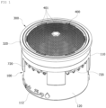
- FIG. 1 is one side perspective view showing a fluid flow control device for a faucet piece according to the present disclosure
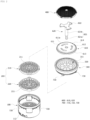
- FIG. 2 is an exploded perspective view viewed from one side of the fluid flow control device for a faucet piece according to the present disclosure
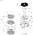
- FIG. 3 is an exploded perspective view of the fluid flow control device for a faucet piece according to the present disclosure viewed from an opposite side
- FIG. 4 is a longitudinal sectional configuration view showing the fluid flow control device for a faucet piece according to the present disclosure
- FIG. 5 shows views explaining a coupling configuration between a first water dispersion member and a second water dispersion member constituting a water dispersion means constituting the fluid flow control device for a faucet piece according to the present disclosure
- FIG. 6 shows plan views illustrating first and second implementation types of a distribution member constituting a fluid control means included in the fluid flow control device for a faucet piece according to the present disclosure.
- the fluid flow control device for a faucet piece is the fluid flow control device (or an aerator) for a faucet piece for controlling water flow by being provided in a spout of the faucet piece, as largely shown in FIG. 1 to FIG. 6 , the device including: a cylindrical type housing 100; a water dispersion means 200 configured to evenly disperse incoming water; a cylindrical type mounting member 300 mounted and fixed to the spout of the faucet piece; a screen mesh member 400; a rotation guide means 500; and a fluid control means 600.
- the fluid flow control device for a faucet piece includes: the cylindrical type housing 100 provided with a plurality of water discharge holes 101 at a bottom part and having an opening portion on an upper side and a predetermined diameter; the water dispersion means 200 provided inside the cylindrical type housing 100 and configured to uniformly disperse water flowing in from the spout of the faucet piece; the cylindrical type mounting member 300 having a lower end portion coupled to be able to rotate to an upper end portion of the cylindrical type housing 100, provided with a plurality of water discharge holes 301 at a bottom part, and fixed to the spout of the faucet piece; the screen mesh member 400 provided at an upper end portion of the cylindrical type mounting member 300 and configured to allow water flowing in through the spout of the faucet piece to be passed therethrough, whereby the water is dispersed while being filtered; the rotation guide means 500 provided between the cylindrical type housing 100 and the cylindrical type mounting member 300 and configured to guide relative rotation of the cylindrical type housing 100 and the
- the cylindrical type housing 100 is provided in a cylindrical type with an upper portion open and a lower surface closed, as a whole, and includes: a large-diameter portion 110 having a relatively large diameter; and a small-diameter portion 120 provided integrally to one end of the large-diameter portion 110, but having a smaller diameter than the large-diameter portion 110 and provided with the water discharge holes 101 in a bottom part 121.
- a step portion 111 is provided at a lower inner periphery of the large-diameter portion 110 protruding along a circumferential direction, and on an upper surface of the step portion 111, an edge of the water dispersion means 200 to be described in detail below is seated and assembled.
- the step portion 111 may be provided, entirely or partially with predetermined intervals, over the lower inner periphery of the large-diameter portion 110 in a circumferential direction. At this time, the step portion 111 may be provided to have certain intervals, that is, as in the case of the latter. In this case, the step portion 111 may allow the water to pass between the intervals where the step portion 111 is provided, thereby, by being in conjunction with the water dispersion means 200, performing a part of the function of the water dispersion means 200.
- the bottom part 121 of the small-diameter portion 120 is provided to have a predetermined thickness, and the water discharge holes 101 are provided in the bottom part 121.
- a fixing hole or fixing groove 122 in which a lower end part of a fluid control rotation blade member 620 configured to rotate with the rotation of the cylindrical type housing 100 is fixedly mounted, is provided.
- cylindrical type housing 100 is provided so that a part of the lower end portion (a part of the small-diameter portion 120) is exposed to the outside of the spout of the faucet piece, and the user holds the exposed part and rotates the cylindrical type housing 100 to control discharge flow rate (or flow velocity, hydraulic pressure, water size, and the like) of the water.
- a flow rate control display 112 is provided on a portion of an outer surface of the lower end portion, which is the exposed part of the cylindrical type housing 100.
- the flow control display unit 112 of the example shown in the drawing shows a case of being provided in an embossed display form.
- a component of a control position stopper means to be described later is provided in the cylindrical type housing 100, and the component will be described in detail below.
- the water dispersion means 200 is a component configured to evenly disperse and spread the water flowing into from the spout of the faucet piece through the screen mesh member 400 and may be provided with one or more plate type lattice network members having water passage holes (for example, grill-type water passage holes) of a predetermined pattern.
- the water dispersion means 200 includes a first lattice network member 210 having water passage holes formed therein as illustrated in the drawing and a second lattice network member 220 having water passage holes having a different size and shape from the water passage holes of the first lattice network member 210.
- Such first lattice network member 210 and the second lattice network member 220 have the same diameter and are seated on the upper surface of the step portion 111 provided in the large-diameter portion 110 of the cylindrical type housing 100.
- the outer diameters of the first lattice network member 210 and the second lattice network member 220 may be the same as or slightly smaller than the inner diameter of the cylindrical type housing 100.
- shaft through-holes 211 and 221 through which the shaft 621 of the fluid control rotation blade member 620, which constitutes the fluid control means 600 and is configured to rotate with the rotation of the cylindrical type housing 100, passes are provided, respectively.
- the water dispersion means 200 includes a plurality of lattice network members, for example including the first lattice network member 210 and the second lattice network member 220, as shown in FIG. 5 , one or more assembly grooves 231 are provided on an outer periphery of one of the first lattice network member 210 and the second lattice network member 220, and assembly protrusions 232, which the assembly grooves 231 are fitted into and fixed to, are provided on an outer periphery of another one of the first lattice network member 210 and the second lattice network member 220.
- the water dispersion means 200 includes two or more lattice network members 210 and 220, the assembly between the lattice network members 210 and 220 may be facilitated, and it may be possible to reduce assembly defects between the lattice network members 210 and 220 by assembling the assembled lattice network members.
- the cylindrical type mounting member 300 includes a cylindrical type body part 310 having a predetermined thickness and provided with a plurality of water discharge holes 301 at a bottom part 311 and a fixing flange portion 320 provided to protrude outward in a radial direction on an outer periphery of an upper end portion of the cylindrical type body part 310, whereby the outer periphery is mounted and fixed to the inner periphery of the spout of the faucet piece.
- a step portion 312 is provided protruding along a circumferential direction, and on an upper surface of the step portion 312, an edge of a flow rate control plate member 610 constituting the fluid control means 600 to be described in detail below is seated and assembled.
- the step portion 312 of the cylindrical type mounting member 300 is provided over the entire periphery of the inner circumferential direction, and this is to maintain the function (flow rate control function) of the flow rate control plate member 610 constituting the fluid control means 600.
- a shaft through-hole 313 through which the shaft of the fluid control rotation blade member 620, which constitutes the fluid control means 600 to be described later and is configured to rotate with the rotation of the cylindrical type housing 100, passes is provided.
- an assembly protrusion 311a (see FIG. 2 ) is formed on one edge of the bottom part 311 of the cylindrical type body part 310 of the cylindrical type mounting member 300, and an assembly groove or assembly cutout part 614, into which the assembly protrusion 311a of the cylindrical type mounting member 300 is fitted, is provided at an edge frame part 613 of the flow rate control plate member 610 constituting the fluid control means 600 to be described later. Therefore, flow rate control plate member 610 may be assembled to be fixed at a position on the cylindrical type mounting member 300 by fitting the assembly protrusion 311a into the assembly groove or assembly cutout part 614.
- assembly protrusion 311a and the assembly groove or assembly cutout 614 may be provided reversely.
- the cylindrical type mounting member 300 may further include a reinforcing fixing means to be able to be mounted in the spout of the faucet piece more robustly and airtightly.
- the reinforcing fixing means may be implemented in such a way that a mounting groove is provided in a circumferential direction on the outer periphery of the upper end of the cylindrical type mounting member 300, that is, on the outer periphery of the fixing flange portion 320 of the cylindrical type mounting member 300, and an annular fixing member (or packing member) having a predetermined width and made of a flexible material (for example, a silicone material or a rubber material) may be mounted and fixed to the mounting groove.
- a mounting groove is provided in a circumferential direction on the outer periphery of the upper end of the cylindrical type mounting member 300, that is, on the outer periphery of the fixing flange portion 320 of the cylindrical type mounting member 300, and an annular fixing member (or packing member) having a predetermined width and made of a flexible material (for example, a silicone material or a rubber material) may be mounted and fixed to the mounting groove.
- the screen mesh member 400 is made of a plate type screen mesh in which a plurality of water passage holes 401 is provided.
- the screen mesh member 400 is provided such that a central portion protrudes to one side compared to an edge.
- the screen mesh member 400 is provided to be inclined downward from a center to the edge.
- a lower surface of the edge of the screen mesh member 400 is seated on an upper surface of an edge of the flow rate control plate member 610, and a central part of the screen mesh member 400 is provided by being spaced apart from the flow rate control plate member 610.
- a supporting protrusion 410 configured to rotate with the rotation of the cylindrical type housing 100 and to come into contact with a center of an upper surface of the fluid control rotation blade member 620 constituting the fluid control means 600 to support the screen mesh member.
- the rotation guide means 500 may include a guide groove and a guide protrusion, each provided in the circumferential direction at corresponding one of parts facing each other between an upper end part of the cylindrical type housing 100 and a lower end part of the cylindrical type mounting member 300.
- the rotation guide means 500 may include: one or more guide grooves 510 provided in the circumferential direction of any one of the facing surfaces between the upper end part of the cylindrical type housing 100 and the lower end part of the cylindrical type mounting member 300; and one or more guide protrusions 520 provided in the circumferential direction of remaining one of the facing surfaces between the upper end part of the cylindrical type housing 100 and the lower end part of the cylindrical type mounting member 300 and guided along the guide groove 510.
- Shown in the drawing is a case in which the guide groove 510 and the guide protrusion 520 both are provided at the upper end part of the cylindrical type housing 100 and the lower end part of the cylindrical type mounting member 300, respectively.
- the case in which each of the guide groove 510 and the guide protrusion 520 is provided in the cylindrical type housing 100 and the cylindrical type mounting member 300 is shown, and by providing the guide groove 510 and the guide protrusion 520 simultaneously in both the cylindrical type housing 100 and the cylindrical type mounting member 300 in this way, it is possible to maintain a more stable coupling and rotation for the device.
- the fluid control means 600 may include: a flow rate control plate member 610 provided to be spaced apart from and interposed between the bottom part 311 of the cylindrical type mounting member 300 and the screen mesh member 400 and having a plurality of flow rate control holes 612; and a fluid control rotation blade member 620 having one side positioned on an upper surface of the flow rate control plate member 610 and an opposite side configured to pass through the shaft through-hole 313 provided in the center of the cylindrical type mounting member 300 and the shaft through-holes 211 and 221 provided in the center of the water dispersion means 200 (that is, the shaft through-holes 211 and 221 provided in the centers of the first and second lattice network members 210 and 220, respectively,) and to be fixed not to be possible to rotate to the fixing hole 122 (or the fixing groove 122) provided in the center of the cylindrical type housing 100, thereby rotating together with the rotation of the cylindrical type housing 100 to control the open degree of the flow rate control holes 612 of the flow rate control plate member 610.
- the flow rate control plate member 610 includes: a plate type body part 611; one or more flow rate control holes 612 provided by passing through the plate type body part 611; an edge frame part 613 having a predetermined width at an edge of the plate type body part 611 and provided to protrude toward one side (that is, cylindrical type mounting member 300 side) ; and one or more assembly grooves or assembly cutout parts 614 provided at the edge frame part 613 and configured to be inserted into the assembly protrusions provided in the bottom part 311 of the cylindrical type body part 310 of the cylindrical type mounting member 300.
- the flow rate control hole 612 is provided in an arc or a slot in an arc shape having a predetermined length.
- a plurality of the flow rate control holes is provided with intervals therebetween at positions on a rotational orbit line that is spaced apart by a predetermined length in the radial direction from a center of the plate type body part 611.
- Such a flow rate control hole 612 may be provided as a slot having a relatively small width (width into a radial direction) at a relatively long distance from the center of the plate type body part 611 as shown in FIG. 6A or as a slot having a relatively large width (width into the radial direction) at a relatively close distance compared to FIG. 6A as shown in FIG. 6B , but the present disclosure is not limited thereto.
- An opening degree (or opening/closing degree) of such a flow rate control hole 612 is adjusted by the rotation of the fluid control rotation blade member 620 rotating together with the cylindrical type housing 100, whereby the flow rate of water is controlled and passed through.
- the flow rate control plate member 610 may be provided by varying a thickness (thickness into the radial direction) of the edge frame part 613, whereby a cover range of the water discharge holes 301 of the cylindrical type mounting member 300 may be varied. Accordingly, the flow rate, flow velocity, hydraulic pressure, and water stream size may be varied along with the flow control according to the rotation of the fluid control rotation blade member 620 described above.
- a shaft through-hole 611a through which the shaft 621 of the fluid control rotation blade member 620 passes through is provided in a center of the plate type body part 611.
- the fluid control rotation blade member 620 includes a shaft 621 having a predetermined length and a plurality of blades 622 integrally provided at one end part (upper end part in the drawing) of the shaft 621.
- the shaft 621 is provided to be stepped in two step portions, and a lower step portion is inserted into and fixed to the shaft through-hole 313 of the cylindrical type housing 100.
- the shaft 621 may include a fixed portion 621a having a lower end inserted into and fixed to the shaft through-hole 313 of the cylindrical type housing 100 and a shaft portion 621b provided by having a diameter larger than a diameter of the fixed portion 621a (in other words, diameter larger than a diameter of the shaft through-hole 313 of the cylindrical type housing 100).
- the fixing part 621a of the shaft 621 is configured to pass through the shaft through-hole 313 provided in the center of the cylindrical type mounting member 300 and the shaft through-holes 211 and 221 provided in the center of the water dispersion means 200 and to be fixed not to be able to rotate to the fixing hole 122 (or the fixing groove 122) provided in the center of the cylindrical type housing 100.
- the blades 622 are provided in a plurality of plate type blades in a fan shape extending outward from one end part of the shaft 621 and are provided to correspond to the number of the flow rate control holes 612.
- the blades 622 are configured to rotate together with the rotation of the cylindrical type housing 100 to control the open degree of the flow rate control holes 612 of the flow rate control plate member 610.
- the blade 622 is provided to have a width that may cover the flow rate control hole 612 corresponding thereto in the rotational direction when the flow rate control hole 612 is closed.
- the fluid flow control device for a faucet piece further includes a control position stopper means 700 configured to maintain a position of the cylindrical type housing 100 rotated with respect to the cylindrical type mounting member 300.
- the control position stopper means 700 may include: a cutout part or slot 710 provided in a predetermined length in the circumferential direction of the cylindrical type housing 100; a prominence and depression portion 720 provided at a lower end of the cutout part or slot 710; and a stopper protrusion 730 provided at a position, corresponding to a position of the cutout part or slot 710, on one side of a lower edge of the cylindrical type mounting member 300and separated from or settled in a depression portion of the prominence and depression portion 720 due to the rotation of the cylindrical type housing 100.
- the cutout part or slot 710 and the stopper protrusion 730 may be provided in the number of at least one, respectively.
- the control positions between the cutout part or slot 710 and the stopper protrusion 730 are provided by being in associated with the opening/closing degree of the flow rate control hole 612 by the blade 622 of the fluid control rotation blade member 620 that rotates together with the rotation of the cylindrical type housing 100.
- the device may be easily used by anyone to control the flow rate, flow velocity, hydraulic pressure, water stream size, and the like besides a basic function of gently discharging discharged water, each component constituting the device is easy to manufacture to promote productivity improvement and manufacturing cost reduction, and each component constituting the device may be easily completely assembled.
- the present disclosure has the effect in that the device may be easily and robustly installed in the spout of the faucet piece, may easily recognize a sense of stepwise control of flow velocity and hydraulic pressure, and may stably maintain a control position to improve usability.
- the present disclosure may be applied to a faucet piece.
Landscapes
- Health & Medical Sciences (AREA)
- Life Sciences & Earth Sciences (AREA)
- Engineering & Computer Science (AREA)
- Hydrology & Water Resources (AREA)
- Public Health (AREA)
- Water Supply & Treatment (AREA)
- Domestic Plumbing Installations (AREA)
Claims (10)
- Dispositif de contrôle du débit de fluide destiné à une pièce de robinetterie, le dispositif comprenant :un corps de type cylindrique (100) doté de plusieurs orifices d'évacuation d'eau (101) sur une partie inférieure du corps de type cylindrique et possédant une partie d'ouverture sur un côté supérieur du corps de type cylindrique ;un moyen de dispersion d'eau (200) disposé à l'intérieur du boîtier (100) et configuré afin de disperser uniformément l'eau qui s'y écoule;un élément de montage de type cylindrique (300) possédant une partie d'extrémité inférieure couplée à une partie d'extrémité supérieure du corps (100), de manière à être rotatif par rapport à la partie d'extrémité supérieure du corps, dans lequel l'élément de montage de type cylindrique est doté d'une pluralité d'orifices d'évacuation d'eau (301) sur une partie inférieure de l'élément de montage de type cylindrique, et fixable à un bec de la pièce de robinetterie ;un élément à maillage de tamis (400) disposé sur une partie d'extrémité supérieure de l'élément de montage (300) ;un moyen de guidage de rotation (500) disposé entre le corps (100) et l'élément de montage (300) et configuré afin de guider une rotation relative du corps (100) et de l'élément de montage (300) ; etun moyen de contrôle de fluide (600) configuré afin de contrôler le débit de l'eau s'écoulant dans le corps (100) du fait de la rotation relative entre le corps (100) et l'élément de montage (300),dans lequelle moyen de contrôle de fluide (600) comprend :un élément à plaque de contrôle du débit (610) disposé de manière à être espacé et interposé entre la partie inférieure de l'élément de montage (300) et l'élément à maillage de tamis (400) et comportant une pluralité d'orifices de contrôle de débit (612) ; etun élément à pales de rotation de contrôle de débit (620) possédant un côté positionné sur une surface supérieure de l'élément à plaque de contrôle de débit (610) et un côté opposé configuré afin de passer à travers l'élément de montage (300) et le moyen de dispersion d'eau (200) et d'être fixé à un orifice de fixation (122) disposé dans un centre du corps (100).
- Dispositif selon la revendication 1, dans lequel l'élément à plaque de contrôle de débit (610) comprend :une partie à corps en forme de plaque (611) ;un ou plusieurs orifices de contrôle de débit (612) disposés par pénétration à travers la partie à corps en forme de plaque (611) ;une partie de structure de bordure (613) disposée afin de dépasser vers un côté de l'élément de montage ; etune ou plusieurs protubérances d'assemblage ou gorges d'assemblage disposées sur la partie de structure de bordure (613) et configurées afin d'être insérées dans les protubérances d'assemblage ou les gorges d'assemblage disposées dans une partie inférieure de l'élément de montage (300), etl'élément à pales de rotation de contrôle de fluide (620) comprend :un arbre (621) possédant une longueur prédéterminée ; etune pluralité de pales (622) disposées sur une partie d'extrémité de l'arbre (621) et positionnées respectivement sur les surfaces supérieures des orifices de contrôle de débit (612).
- Dispositif selon la revendication 2, dans lequel les orifices de contrôle de débit (612) sont disposés dans une pluralité de fentes, chacune en forme d'arc, avec des intervalles entre elles à des positions sur une ligne d'orbite rotative qui est espacée d'une longueur prédéterminée dans une direction radiale à partir d'un centre de la partie à corps en forme de plaque (611), et
les pales (622) sont disposées dans une pluralité de pales en forme de plaques dans une forme en éventail s'étendant vers l'extérieur à partir d'une partie d'extrémité de l'arbre (621). - Dispositif selon la revendication 1, dans lequel le moyen de dispersion d'eau (200) est doté d'un ou plusieurs éléments de réseau de treillis en forme de plaque (210, 220) possédant chacun une pluralité d'orifices de passage d'eau et un orifice de passage d'arbre en son centre,l'élément à maillage de tamis (400) est fabriqué en un maillage de tamis en forme de plaque possédant une pluralité d'orifices de passage d'eau (401),l'élément de montage (300) comprend :une partie de corps de type cylindrique (310) dotée de la pluralité d'orifices d'évacuation d'eau (301) sur la partie inférieure et d'un orifice de passage d'arbre (313) en son centre ; etune partie à bride de fixation (320) disposée afin de dépasser vers l'extérieur dans une direction radiale sur une périphérie extérieure d'une extrémité supérieure de la partie de corps (310),le corps (100) comprend :une partie à grand diamètre (110) possédant un diamètre prédéterminé ; etune partie à petit diamètre (120) possédant un diamètre plus petit que la partie à grand diamètre (110) et dotée des orifices d'évacuation d'eau (101) dans une partie inférieure,sur une périphérie interne inférieure de la partie à grand diamètre (110), une partie à décrochement (111) est disposée afin de dépasser le long d'une direction circonférentielle, etdans un centre de la partie inférieure de la partie à petit diamètre (120) est prévu un orifice de fixation ou une gorge de fixation, dans quoi une partie d'extrémité inférieure de l'élément à pales de rotation de contrôle de fluide (620) constituant le moyen de contrôle de fluide (600) est montée de manière fixe.
- Dispositif selon la revendication 1, dans lequel le moyen de dispersion d'eau (200) comporte :un premier élément de réseau de treillis (210) possédant des orifices de passage d'eau ; etun second élément de réseau de treillis (220) possédant des orifices de passage d'eau ayant une taille et une forme différentes des orifices de passage d'eau du premier élément de réseau de treillis (210),dans lequel, sur une périphérie extérieure d'un quelconque du premier élément de réseau de treillis (210) et du second élément de réseau de treillis (220), au moins une quelconque des gorges d'assemblage et/ou des protubérances d'assemblage est disposée, etsur une périphérie extérieure d'un autre quelconque du premier élément de réseau de treillis (210) et du second élément de réseau de treillis (220), au moins une quelconque des gorges d'assemblage et/ou des protubérances d'assemblage est disposée.
- Dispositif selon la revendication 1, dans lequel, sur une bordure de la partie inférieure (311) de l'élément de montage (300), une protubérance d'assemblage ou une gorge d'assemblage est disposée, et
sur une partie de structure de bordure (613) de l'élément à plaque de contrôle de débit (610), une gorge d'assemblage ou une protubérance d'assemblage est disposée, qui est assemblée avec la protubérance d'assemblage ou la gorge d'assemblage de l'élément de montage (300). - Dispositif selon la revendication 1, dans lequel l'élément à maillage de tamis (400) est disposé afin d'être incliné vers le bas d'un centre vers la bordure, et sur un centre de la surface inférieure de l'élément à maillage de tamis (400) est prévue une protubérance de support, configurée afin d'entrer en contact avec un centre d'une surface supérieure de l'élément à pales de rotation de contrôle de fluide (620) afin de soutenir l'élément à maillage de tamis (400).
- Dispositif selon la revendication 1, dans lequel le moyen de guidage de rotation (500) comprend une gorge de guidage (510) et une protubérance de guidage (520), chacune disposée dans la direction circonférentielle sur une quelconque correspondante des parties situées face à face l'une de l'autre entre une partie d'extrémité supérieure du corps (100) et une partie d'extrémité inférieure de l'élément de montage (300), et
le dispositif comprend par ailleurs :une gorge de montage disposée dans une direction circonférentielle sur la périphérie externe de l'extrémité supérieure de l'élément de montage (300) ; etun élément de fixation annulaire possédant une largeur prédéterminée et fabriqué en un matériau flexible, étant ici monté et fixé à la gorge de montage. - Dispositif selon la revendication 1, comprenant par ailleurs un moyen d'arrêt de position de commande (700) configuré afin de maintenir une position du corps (100) en rotation par rapport à l'élément de montage (300).
- Dispositif selon la revendication 9, dans lequel le moyen d'arrêt de position de commande (700) comprend :une fente (710) disposée à une longueur prédéterminée dans la direction circonférentielle du corps(100) ;une proéminence et une partie en dépression disposées sur une extrémité inférieure de la fente (710) ; etune protubérance d'arrêt (730) disposée dans une position correspondant à la position de la fente (710), sur un côté d'une bordure inférieure de l'élément de montage (300) et séparée ou installée dans une partie en dépression de la protubérance et de la partie en dépression du fait de la rotation du corps (100).
Applications Claiming Priority (3)
| Application Number | Priority Date | Filing Date | Title |
|---|---|---|---|
| KR1020190156020A KR102092224B1 (ko) | 2019-11-28 | 2019-11-28 | 수전금구용 유체 흐름 제어 장치 |
| KR1020190155991A KR102096569B1 (ko) | 2019-11-28 | 2019-11-28 | 수전금구용 유체 흐름 제어 장치 |
| PCT/KR2019/017263 WO2021107245A1 (fr) | 2019-11-28 | 2019-12-09 | Dispositif de commande de débit de fluide d'une pièce de robinet |
Publications (4)
| Publication Number | Publication Date |
|---|---|
| EP4047145A1 EP4047145A1 (fr) | 2022-08-24 |
| EP4047145A4 EP4047145A4 (fr) | 2023-11-15 |
| EP4047145B1 true EP4047145B1 (fr) | 2024-11-20 |
| EP4047145C0 EP4047145C0 (fr) | 2024-11-20 |
Family
ID=76130294
Family Applications (1)
| Application Number | Title | Priority Date | Filing Date |
|---|---|---|---|
| EP19953938.8A Active EP4047145B1 (fr) | 2019-11-28 | 2019-12-09 | Dispositif de commande de débit de fluide d'une pièce de robinet |
Country Status (4)
| Country | Link |
|---|---|
| US (1) | US11933030B2 (fr) |
| EP (1) | EP4047145B1 (fr) |
| CN (1) | CN114729528B (fr) |
| WO (1) | WO2021107245A1 (fr) |
Families Citing this family (2)
| Publication number | Priority date | Publication date | Assignee | Title |
|---|---|---|---|---|
| DE202020101430U1 (de) * | 2020-03-16 | 2021-06-17 | Neoperl Gmbh | Sanitäre Einsetzpatrone |
| DE202020101900U1 (de) * | 2020-04-07 | 2021-07-13 | Neoperl Gmbh | Sanitäres Einsetzteil |
Family Cites Families (22)
| Publication number | Priority date | Publication date | Assignee | Title |
|---|---|---|---|---|
| GB698691A (en) * | 1949-11-29 | 1953-10-21 | Elie Prodromos Aghnides | Mixing devices for liquid and gas |
| US4530467A (en) * | 1983-02-09 | 1985-07-23 | Bueno Humberto E | Adjustable valve for faucet or shower head |
| US5397064A (en) * | 1993-10-21 | 1995-03-14 | Heitzman; Charles J. | Shower head with variable flow rate, pulsation and spray pattern |
| US5518181A (en) * | 1994-05-18 | 1996-05-21 | Shames; Sidney J. | Variable spray or variable pulse shower head |
| JPH1025779A (ja) * | 1996-07-10 | 1998-01-27 | Inax Corp | 自動水栓 |
| KR200209234Y1 (ko) | 1998-08-27 | 2001-01-15 | 김종기 | 절수기 헤드 |
| US6412710B1 (en) * | 2001-05-17 | 2002-07-02 | Yen Tang Lin | Sprayer device having various kinds of outward flows |
| JP4100693B2 (ja) * | 2004-09-07 | 2008-06-11 | アイ・ランドシステム 株式会社 | 流量制御弁 |
| US7314062B2 (en) * | 2004-12-13 | 2008-01-01 | Chuan-Lung Chen | Water control structure for the spout of faucets |
| US7322535B2 (en) * | 2005-01-24 | 2008-01-29 | Newfrey, Llc | Faucet spray head |
| JP2007154975A (ja) * | 2005-12-02 | 2007-06-21 | Tsuneaki Ito | 流量制御弁 |
| DE202006011149U1 (de) * | 2006-07-19 | 2007-12-06 | Neoperl Gmbh | Auslaufmundstück |
| CN100580295C (zh) * | 2007-02-09 | 2010-01-13 | 陈启岳 | 改进结构的温控水龙头 |
| US8272583B2 (en) * | 2009-05-29 | 2012-09-25 | Rain Bird Corporation | Sprinkler with variable arc and flow rate and method |
| JP2011033133A (ja) * | 2009-08-03 | 2011-02-17 | Toyo Keiki Co Ltd | 流量調整器 |
| KR200462332Y1 (ko) | 2011-03-23 | 2012-09-06 | 박문석 | 수도의 절수장치 |
| US8689830B2 (en) * | 2011-07-20 | 2014-04-08 | Chuan Wei Metal Co., Ltd. | Spin controlled faucet outlet structure |
| KR101371780B1 (ko) * | 2012-05-15 | 2014-03-07 | 대림통상 주식회사 | 절수 어댑터 |
| KR101323466B1 (ko) * | 2013-06-17 | 2013-10-29 | 최의택 | 유량 조절 기능을 갖는 수도기기 장착용 절수장치 |
| KR101364886B1 (ko) * | 2013-11-01 | 2014-02-19 | 권중천 | 절수형 샤워기 헤드 |
| SE540044C2 (sv) * | 2015-03-23 | 2018-03-06 | Ngl Teknik I Linkoeping Ab | Ställbar flödesbegränsare för en blandare och ett förfarandeför att ställa flödet |
| KR101625095B1 (ko) * | 2015-05-08 | 2016-05-27 | 최의택 | 자동 조절기능을 갖는 수도꼭지용 절수장치 |
-
2019
- 2019-12-09 EP EP19953938.8A patent/EP4047145B1/fr active Active
- 2019-12-09 WO PCT/KR2019/017263 patent/WO2021107245A1/fr not_active Ceased
- 2019-12-09 CN CN201980102296.9A patent/CN114729528B/zh not_active Expired - Fee Related
-
2022
- 2022-05-09 US US17/739,422 patent/US11933030B2/en active Active
Also Published As
| Publication number | Publication date |
|---|---|
| CN114729528B (zh) | 2024-06-21 |
| US11933030B2 (en) | 2024-03-19 |
| WO2021107245A1 (fr) | 2021-06-03 |
| EP4047145C0 (fr) | 2024-11-20 |
| EP4047145A4 (fr) | 2023-11-15 |
| CN114729528A (zh) | 2022-07-08 |
| EP4047145A1 (fr) | 2022-08-24 |
| US20220259842A1 (en) | 2022-08-18 |
Similar Documents
| Publication | Publication Date | Title |
|---|---|---|
| US6283447B1 (en) | Mixing valve with limit stop and pre-set | |
| EP3377792B1 (fr) | Régulateur d'écoulement réglable | |
| US11933030B2 (en) | Fluid flow control device for faucet piece | |
| JP3415156B2 (ja) | 衛生混合弁 | |
| JP2008297862A (ja) | 節水部材及びそれを用いた節水具 | |
| EP1956150B1 (fr) | Robinet de contrôle de température avec structure améliorée | |
| KR101135338B1 (ko) | 수전부착형 절수 어댑터 | |
| CN206881278U (zh) | 一种可调节美容液浓度的美容滤芯及花洒 | |
| CA2496138A1 (fr) | Melangeur a monter en rattrapage et methode d'assemblage | |
| KR102092224B1 (ko) | 수전금구용 유체 흐름 제어 장치 | |
| KR101323466B1 (ko) | 유량 조절 기능을 갖는 수도기기 장착용 절수장치 | |
| RU2331812C2 (ru) | Сантехническое водоразборное устройство | |
| WO2012142903A1 (fr) | Pomme de douche | |
| US6802424B2 (en) | Strainer in shower bath tap valve | |
| JP4237025B2 (ja) | 節水具及び節水装置 | |
| US7334604B1 (en) | Faucet having multiple different water outlet manners | |
| KR102096569B1 (ko) | 수전금구용 유체 흐름 제어 장치 | |
| JP3274658B2 (ja) | 流量調節弁およびシャワーヘッド | |
| EP0254466A2 (fr) | Tête de pulvérisation réglable pour la toilette | |
| JP2004073958A (ja) | シャワヘッド | |
| CN220910586U (zh) | 一种洗脸台盆用转动式水龙头 | |
| CN217422274U (zh) | 一种出水装置 | |
| JP2025125688A (ja) | 水栓 | |
| JP2005336758A (ja) | 埋込式水栓 | |
| KR20170011030A (ko) | 절수형 수전 카트리지 |
Legal Events
| Date | Code | Title | Description |
|---|---|---|---|
| STAA | Information on the status of an ep patent application or granted ep patent |
Free format text: STATUS: THE INTERNATIONAL PUBLICATION HAS BEEN MADE |
|
| PUAI | Public reference made under article 153(3) epc to a published international application that has entered the european phase |
Free format text: ORIGINAL CODE: 0009012 |
|
| STAA | Information on the status of an ep patent application or granted ep patent |
Free format text: STATUS: REQUEST FOR EXAMINATION WAS MADE |
|
| 17P | Request for examination filed |
Effective date: 20220519 |
|
| AK | Designated contracting states |
Kind code of ref document: A1 Designated state(s): AL AT BE BG CH CY CZ DE DK EE ES FI FR GB GR HR HU IE IS IT LI LT LU LV MC MK MT NL NO PL PT RO RS SE SI SK SM TR |
|
| RAP1 | Party data changed (applicant data changed or rights of an application transferred) |
Owner name: RUESCHO-SCHOTENROEHR GMBH |
|
| DAV | Request for validation of the european patent (deleted) | ||
| DAX | Request for extension of the european patent (deleted) | ||
| A4 | Supplementary search report drawn up and despatched |
Effective date: 20231017 |
|
| RIC1 | Information provided on ipc code assigned before grant |
Ipc: E03C 1/084 20060101ALI20231011BHEP Ipc: E03C 1/086 20060101AFI20231011BHEP |
|
| GRAP | Despatch of communication of intention to grant a patent |
Free format text: ORIGINAL CODE: EPIDOSNIGR1 |
|
| STAA | Information on the status of an ep patent application or granted ep patent |
Free format text: STATUS: GRANT OF PATENT IS INTENDED |
|
| RIC1 | Information provided on ipc code assigned before grant |
Ipc: E03C 1/084 20060101ALI20240429BHEP Ipc: E03C 1/086 20060101AFI20240429BHEP |
|
| INTG | Intention to grant announced |
Effective date: 20240521 |
|
| GRAJ | Information related to disapproval of communication of intention to grant by the applicant or resumption of examination proceedings by the epo deleted |
Free format text: ORIGINAL CODE: EPIDOSDIGR1 |
|
| STAA | Information on the status of an ep patent application or granted ep patent |
Free format text: STATUS: REQUEST FOR EXAMINATION WAS MADE |
|
| GRAP | Despatch of communication of intention to grant a patent |
Free format text: ORIGINAL CODE: EPIDOSNIGR1 |
|
| STAA | Information on the status of an ep patent application or granted ep patent |
Free format text: STATUS: GRANT OF PATENT IS INTENDED |
|
| GRAS | Grant fee paid |
Free format text: ORIGINAL CODE: EPIDOSNIGR3 |
|
| INTC | Intention to grant announced (deleted) | ||
| GRAA | (expected) grant |
Free format text: ORIGINAL CODE: 0009210 |
|
| STAA | Information on the status of an ep patent application or granted ep patent |
Free format text: STATUS: THE PATENT HAS BEEN GRANTED |
|
| INTG | Intention to grant announced |
Effective date: 20240925 |
|
| RIN1 | Information on inventor provided before grant (corrected) |
Inventor name: KWON, BOK MIN |
|
| AK | Designated contracting states |
Kind code of ref document: B1 Designated state(s): AL AT BE BG CH CY CZ DE DK EE ES FI FR GB GR HR HU IE IS IT LI LT LU LV MC MK MT NL NO PL PT RO RS SE SI SK SM TR |
|
| REG | Reference to a national code |
Ref country code: GB Ref legal event code: FG4D |
|
| REG | Reference to a national code |
Ref country code: CH Ref legal event code: EP |
|
| REG | Reference to a national code |
Ref country code: DE Ref legal event code: R096 Ref document number: 602019062441 Country of ref document: DE |
|
| REG | Reference to a national code |
Ref country code: IE Ref legal event code: FG4D |
|
| U01 | Request for unitary effect filed |
Effective date: 20241212 |
|
| U07 | Unitary effect registered |
Designated state(s): AT BE BG DE DK EE FI FR IT LT LU LV MT NL PT RO SE SI Effective date: 20241223 |
|
| U20 | Renewal fee for the european patent with unitary effect paid |
Year of fee payment: 6 Effective date: 20241219 |
|
| PG25 | Lapsed in a contracting state [announced via postgrant information from national office to epo] |
Ref country code: HR Free format text: LAPSE BECAUSE OF FAILURE TO SUBMIT A TRANSLATION OF THE DESCRIPTION OR TO PAY THE FEE WITHIN THE PRESCRIBED TIME-LIMIT Effective date: 20241120 Ref country code: IS Free format text: LAPSE BECAUSE OF FAILURE TO SUBMIT A TRANSLATION OF THE DESCRIPTION OR TO PAY THE FEE WITHIN THE PRESCRIBED TIME-LIMIT Effective date: 20250320 |
|
| PG25 | Lapsed in a contracting state [announced via postgrant information from national office to epo] |
Ref country code: ES Free format text: LAPSE BECAUSE OF FAILURE TO SUBMIT A TRANSLATION OF THE DESCRIPTION OR TO PAY THE FEE WITHIN THE PRESCRIBED TIME-LIMIT Effective date: 20241120 |
|
| PG25 | Lapsed in a contracting state [announced via postgrant information from national office to epo] |
Ref country code: NO Free format text: LAPSE BECAUSE OF FAILURE TO SUBMIT A TRANSLATION OF THE DESCRIPTION OR TO PAY THE FEE WITHIN THE PRESCRIBED TIME-LIMIT Effective date: 20250220 |
|
| PG25 | Lapsed in a contracting state [announced via postgrant information from national office to epo] |
Ref country code: GR Free format text: LAPSE BECAUSE OF FAILURE TO SUBMIT A TRANSLATION OF THE DESCRIPTION OR TO PAY THE FEE WITHIN THE PRESCRIBED TIME-LIMIT Effective date: 20250221 |
|
| PG25 | Lapsed in a contracting state [announced via postgrant information from national office to epo] |
Ref country code: PL Free format text: LAPSE BECAUSE OF FAILURE TO SUBMIT A TRANSLATION OF THE DESCRIPTION OR TO PAY THE FEE WITHIN THE PRESCRIBED TIME-LIMIT Effective date: 20241120 |
|
| PG25 | Lapsed in a contracting state [announced via postgrant information from national office to epo] |
Ref country code: RS Free format text: LAPSE BECAUSE OF FAILURE TO SUBMIT A TRANSLATION OF THE DESCRIPTION OR TO PAY THE FEE WITHIN THE PRESCRIBED TIME-LIMIT Effective date: 20250220 |
|
| PG25 | Lapsed in a contracting state [announced via postgrant information from national office to epo] |
Ref country code: SM Free format text: LAPSE BECAUSE OF FAILURE TO SUBMIT A TRANSLATION OF THE DESCRIPTION OR TO PAY THE FEE WITHIN THE PRESCRIBED TIME-LIMIT Effective date: 20241120 |
|
| U1O | Appointed representative for the unitary patent procedure deleted after the registration of the unitary effect | ||
| PG25 | Lapsed in a contracting state [announced via postgrant information from national office to epo] |
Ref country code: SK Free format text: LAPSE BECAUSE OF FAILURE TO SUBMIT A TRANSLATION OF THE DESCRIPTION OR TO PAY THE FEE WITHIN THE PRESCRIBED TIME-LIMIT Effective date: 20241120 |
|
| PG25 | Lapsed in a contracting state [announced via postgrant information from national office to epo] |
Ref country code: CZ Free format text: LAPSE BECAUSE OF FAILURE TO SUBMIT A TRANSLATION OF THE DESCRIPTION OR TO PAY THE FEE WITHIN THE PRESCRIBED TIME-LIMIT Effective date: 20241120 |
|
| REG | Reference to a national code |
Ref country code: CH Ref legal event code: PL |
|
| PG25 | Lapsed in a contracting state [announced via postgrant information from national office to epo] |
Ref country code: MC Free format text: LAPSE BECAUSE OF FAILURE TO SUBMIT A TRANSLATION OF THE DESCRIPTION OR TO PAY THE FEE WITHIN THE PRESCRIBED TIME-LIMIT Effective date: 20241120 |
|
| PLBE | No opposition filed within time limit |
Free format text: ORIGINAL CODE: 0009261 |
|
| STAA | Information on the status of an ep patent application or granted ep patent |
Free format text: STATUS: NO OPPOSITION FILED WITHIN TIME LIMIT |
|
| PG25 | Lapsed in a contracting state [announced via postgrant information from national office to epo] |
Ref country code: CH Free format text: LAPSE BECAUSE OF NON-PAYMENT OF DUE FEES Effective date: 20241231 |
|
| 26N | No opposition filed |
Effective date: 20250821 |
|
| PG25 | Lapsed in a contracting state [announced via postgrant information from national office to epo] |
Ref country code: IE Free format text: LAPSE BECAUSE OF NON-PAYMENT OF DUE FEES Effective date: 20241209 |
|
| PGFP | Annual fee paid to national office [announced via postgrant information from national office to epo] |
Ref country code: GB Payment date: 20251219 Year of fee payment: 7 |
|
| U20 | Renewal fee for the european patent with unitary effect paid |
Year of fee payment: 7 Effective date: 20251230 |