EP4047155A1 - Verlängerungsstange für ein werkzeug und glättungseinheit mit einer solchen stange - Google Patents
Verlängerungsstange für ein werkzeug und glättungseinheit mit einer solchen stange Download PDFInfo
- Publication number
- EP4047155A1 EP4047155A1 EP21216862.9A EP21216862A EP4047155A1 EP 4047155 A1 EP4047155 A1 EP 4047155A1 EP 21216862 A EP21216862 A EP 21216862A EP 4047155 A1 EP4047155 A1 EP 4047155A1
- Authority
- EP
- European Patent Office
- Prior art keywords
- handle
- fixing
- pole
- knife
- fixing part
- Prior art date
- Legal status (The legal status is an assumption and is not a legal conclusion. Google has not performed a legal analysis and makes no representation as to the accuracy of the status listed.)
- Granted
Links
Images


Classifications
-
- E—FIXED CONSTRUCTIONS
- E04—BUILDING
- E04F—FINISHING WORK ON BUILDINGS, e.g. STAIRS, FLOORS
- E04F21/00—Implements for finishing work on buildings
- E04F21/02—Implements for finishing work on buildings for applying plasticised masses to surfaces, e.g. plastering walls
- E04F21/16—Implements for after-treatment of plaster or the like before it has hardened or dried, e.g. smoothing-tools, profile trowels
- E04F21/161—Trowels
- E04F21/163—Trowels with exchangeable blades
-
- B—PERFORMING OPERATIONS; TRANSPORTING
- B25—HAND TOOLS; PORTABLE POWER-DRIVEN TOOLS; MANIPULATORS
- B25G—HANDLES FOR HAND IMPLEMENTS
- B25G1/00—Handle constructions
- B25G1/04—Handle constructions telescopic; extensible; sectional
-
- B—PERFORMING OPERATIONS; TRANSPORTING
- B25—HAND TOOLS; PORTABLE POWER-DRIVEN TOOLS; MANIPULATORS
- B25G—HANDLES FOR HAND IMPLEMENTS
- B25G3/00—Attaching handles to the implements
- B25G3/02—Socket, tang, or like fixings
-
- B—PERFORMING OPERATIONS; TRANSPORTING
- B05—SPRAYING OR ATOMISING IN GENERAL; APPLYING FLUENT MATERIALS TO SURFACES, IN GENERAL
- B05C—APPARATUS FOR APPLYING FLUENT MATERIALS TO SURFACES, IN GENERAL
- B05C17/00—Hand tools or apparatus using hand held tools, for applying liquids or other fluent materials to, for spreading applied liquids or other fluent materials on, or for partially removing applied liquids or other fluent materials from, surfaces
- B05C17/10—Hand tools for removing partially or for spreading or redistributing applied liquids or other fluent materials, e.g. colour touchers
-
- B—PERFORMING OPERATIONS; TRANSPORTING
- B05—SPRAYING OR ATOMISING IN GENERAL; APPLYING FLUENT MATERIALS TO SURFACES, IN GENERAL
- B05C—APPARATUS FOR APPLYING FLUENT MATERIALS TO SURFACES, IN GENERAL
- B05C3/00—Apparatus in which the work is brought into contact with a bulk quantity of liquid or other fluent material
- B05C3/18—Apparatus in which the work is brought into contact with a bulk quantity of liquid or other fluent material only one side of the work coming into contact with the liquid or other fluent material
-
- B—PERFORMING OPERATIONS; TRANSPORTING
- B25—HAND TOOLS; PORTABLE POWER-DRIVEN TOOLS; MANIPULATORS
- B25G—HANDLES FOR HAND IMPLEMENTS
- B25G1/00—Handle constructions
- B25G1/10—Handle constructions characterised by material or shape
- B25G1/102—Handle constructions characterised by material or shape the shape being specially adapted to facilitate handling or improve grip
-
- E—FIXED CONSTRUCTIONS
- E04—BUILDING
- E04F—FINISHING WORK ON BUILDINGS, e.g. STAIRS, FLOORS
- E04F21/00—Implements for finishing work on buildings
- E04F21/02—Implements for finishing work on buildings for applying plasticised masses to surfaces, e.g. plastering walls
- E04F21/06—Implements for applying plaster, insulating material, or the like
Definitions
- the invention relates to an extension pole for a tool such as a putty knife, a trowel or the like, to a method for implementing said pole, and to a smoothing assembly comprising such a pole and such a tool.
- the invention relates to an extension pole for tools, such as putty knives, of the type having a handle consisting of a profile, for example obtained by extrusion, arranged parallel to the edge of the blade.
- a handle consisting of a profile, for example obtained by extrusion, arranged parallel to the edge of the blade.
- This type of handle has the advantage of allowing the manufacture of the handle with a profile which can be cut to the desired length. It is thus possible to manufacture very wide coating knives, which allows faster and more homogeneous work, because the application force is transmitted over the entire width of the blade.
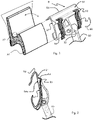
- the handle A of the document coating knife FR2913705 illustrated in figure 1 , has a lever zone A1 which is placed in the hollow of the thumb, during use, and a grip zone comprising a convex curved front grip face A2, against which the user's fingers can bend.
- lever zone A1 when the user applies the putty knife against the wall, he applies a significant smoothing force with one or two hands, thanks to the lever zone A1.
- this lever zone is strongly held by the user, because it undergoes the greatest stress during smoothing.
- the document FR2913705 evokes an extension pole comprising a handle and a fixing end of complementary shape to the handle A of the knife to be coated, without detailing the structure of this end.
- An extension pole B for the document coating knife FR2913705 is already marketed and illustrated in figures 1 and 2 .
- This extension was designed to mimic the motion of the user's hand by pinching the back of the handle for leverage, like the user's thumb, and squeezing the front grip area tightly, like the fingers of the user. the user.
- the fixing end B1 has a shape complementary to the profile of the handle A of the knife to be coated.
- the attachment end B1 also comprises a rotationally adjustable attachment means B2, such as a ball joint, for attachment to the handle B3 of the pole.
- the fixing part B1 also comprises two fixing lugs B4 articulated on a rib (as illustrated in figures 1 and 2 ) B5 reinforcement arranged on the distal part located in front of the attachment part B1, that is to say towards the edge B6 of the gripping portion B1 farthest from the handle B3.
- the reinforcing rib B5 is arranged substantially above the grip zone A2 of the handle A of the knife to be coated, when it is fixed to the fixing part B1, and therefore at a distance from the lever zone A1 of said handle.
- the B4 brackets include a B4a rib (see picture 2 ) of forceful contact with the handle A of the knife to be coated.
- the force-contact ribs are force-pressed against the handle and firmly hold the latter in the fastening part.
- the rib of each lug B4 protrudes from the inner surface B7 of the fixing part intended to be in contact with the handle of the knife to be coated, which is illustrated in picture 2 .
- This pole is impractical because of its position of use.
- the latter makes it necessary to handle the knife to be coated in the immediate vicinity of the ground, which risks damaging or dirtying it.
- the implementation of the pole is slow, because it requires a lot of manipulations.
- the smoothness of the coating obtained is of lower quality than when the same knife is operated by hand.
- One objective of the present invention is therefore to provide a pole that is easy to implement, practical, quick and safe.
- Another object of the present invention is to provide a pole which provides smoothing identical to the smoothing obtained manually with the coating knife alone, in particular with coating knives of great length, that is to say greater than at least 50 cm long, especially knives 80-100 cm long.
- the idea underlying the invention was to move the location of the fixing lugs by articulating them at the rear of the fixing part, close to the fixing means adjustable in rotation (such as a ball joint) from handle, above the lever zone of the handle of the knife to be coated when the latter is slid into the fixing part of the pole, and so as to cover the front of the fixing part when they are in fixing position.
- Another idea has been to increase, in a preferred embodiment, the contact surface with the fixing part by bringing the two tabs together by a grip tab shaped to lock on the front part of the fixing part located at the above the grip zone of the handle of the knife to be coated when the latter is inserted therein, which concomitantly makes implementation much simpler.
- the subject of the invention is more precisely a pole for a putty knife provided with a handle constituted by a profile, for example obtained by extrusion, the pole comprising a handle, and a member for fixing the handle to a first fixing part of the handle of the knife to be coated, the first fixing part having a contact surface of a shape complementary to the profile of the handle of the knife to be coated, a distal part close to the blade of the knife to be coated when the latter is fixed in the first fixing part in the position of use, and a proximal part arranged opposite the distal part, close to the handle, the first fixing part further comprising at least two fixing lugs mounted in a pivoting manner, the fixing lugs being articulated on the proximal part of the first fixing part and shaped to fall back on the distal part of the first fixing part.
- the articulation of the fixing lugs on the distal part of the fixing part allows the handle of the knife to be coated to be tightened by the ribs of the fixing lugs at the level of the lever zone of the handle, while stiffening the grip at the level of the gripping zone of the handle thanks to the gripping part of the fixing lugs which comes to fold back against the distal edge of the fixing part.
- This arrangement ensures easier use while allowing better maintenance of the handle than with a state-of-the-art extension, as well as a smoothing quality identical to what is obtained manually with the putty knife alone.
- the invention also relates to a smoothing assembly comprising a previous pole and at least one coating knife comprising a profiled handle of complementary shape to the first attachment part of the pole.
- a first embodiment of the pole according to the invention is illustrated in picture 3 .
- the pole is illustrated "head up", that is to say the handle resting on the ground and the fixing part of the knife to be coated upwards.
- the pole 1 therefore comprises a handle 10 fixed to a first fixing part 20 of the handle of the knife to be coated by means of a fixing member 30.
- this fixing member is of the type with allow an angle-adjustable fixing between the handle and the fixing part to the knife to be coated, such as for example a ball joint.
- the first attachment part 20 is a profile which has a contact surface 21 of a shape complementary to the profile of the handle of the knife to be coated, so that said handle can be slid into the first attachment part 20 (see figures 6 to 8 ).
- the first fixing part 20 comprises a distal part 22 arranged close to the blade of the knife to be coated in the position of use, that is to say when the knife is fixed in the first fixing part 20.
- the first fixing part 20 also comprises a proximal part 23 arranged opposite the distal part 22 and close to the handle 10.
- the first fixing part 20 further comprises at least two fixing lugs 24 pivotally mounted on the proximal part 23 of the first fixing part 20 and shaped to fall back on the distal part of the first fixing part.
- This arrangement allows clamping above the lever area of the putty knife handle, which remarkably improves the quality of the hold of the putty knife and, therefore, the quality of the smoothness of the putty with a pole.
- the first fixing part 20 comprises a reinforcing rib 25 arranged transversely along the proximal part 23, the at least two fixing lugs being articulated on this reinforcing rib 25.
- the fixing lugs 24 have an articulation portion 26 on the first fixing part, and a gripping portion 27 enabling the user to grasp them in order to pivot them between an open position to insert a putty knife, and a position of use in which the fixing lugs press in force against the handle of the knife to be coated by means of their clamping rib 28 (see figure 5 ).
- the gripping portion 27 comprises a free end shaped to lock onto the distal part 22 of the first fixing part 20, that is to say to lock against the distal edge 29 of the first fixing part the farther from the handle.
- This allows for anterior and posterior fixation of the first fixing part 20 on the handle of the knife to be coated, i.e. a clamp above the front gripping area of the handle of the knife to be coated, and a clamp above the lever area of the handle of the knife to be coated., further improving the quality of the hold of the handle and therefore the quality of the smoothing.
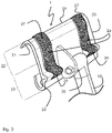
- FIG. 4 A second very interesting embodiment of a pole according to the invention is illustrated in figure 4 .
- each lug 24 is connected to each other by their gripping portion 27a which is therefore common to the two lugs 24.
- each lug 24 has its own hinge portion 26 on the first fixing part 20.
- the two fixing lugs 24 are connected to each other by their gripping portion 27a so as to leave a space E between their hinge portions sufficient to allow the handle fixing member to pass. As shown by the figures 4 and 5 , this allows simultaneous closing and opening of the fixing lugs without being hampered by the presence of the fixing member of the handle and of the handle itself.
- FIGS. 6 to 8 illustrate a method of using the pole according to the invention. These figures illustrate the second embodiment in which the fixing lugs are integral with one another via their gripping portion. However, this method is similar to the first embodiment, with the only difference that it will be necessary to deactivate and activate the fixing lugs sequentially and not simultaneously.
- the user places the handle of the pole on the ground so that the first fixing part 20 is directed upwards. Then he rotates the fixing lugs 24 downwards, in the direction of the arrow F1, so that the force contact ribs 28 are retracted from the contact surface with the handle of the knife to be coated.
- the gripping portion is shaped to lock against the distal edge of the first fixing part, so that additional tightening is obtained.
- the user again positions the pole “head upwards”, then he lowers the fixing lugs 24 downwards, in the direction of the arrow F1.
- the spring effect of the fixing lugs previously wedged in force against the handle of the knife via the ribs 28, will help the user to position the fixing lugs 24 in the open position.
- the arrangement of the fixing lugs 24 according to the invention also allows the easy use, without risk of damaging the knife to be coated, of a reinforcement system 40 for long knives to be coated.
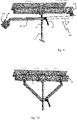
- This third embodiment is illustrated in figures 9 and 10 .
- the pole further comprises a ring 41 mounted to slide along the handle 10 and provided with a reversible locking means 42 illustrated here by example by a quick-tightening handle.
- the ring 41 is pivotally connected to a first end of an arm 43 connected, at a second end, to a second fixing part 20a of the handle of the knife to be coated.
- the ring is connected to two arms 43 each provided with a second part 20a for fixing the handle of the knife to be coated.
- the second fixing part 20a is connected to the second end of the arm in a pivoting manner to allow it to be threaded onto the handle of the knife to be coated.
- the implementation is very simple: to fix the reinforcement system 40, the user positions the pole "head up” and releases the ring 41, that is to say that he deactivates the fixing means 42 from so that the ring is free to slide along the handle.
- the arms 43 can be telescopic.
- this reinforcement system is made possible by the particular arrangement of the fixing lugs 24 which allows great freedom of movement, and avoids having to maintain them to maintain the open position.
- the use of the reinforcement system 40 according to the invention makes it possible to obtain a smoothing identical to the smoothing obtained manually with the coating knife alone, that is to say without a pole, in particular with very long coating knives. , that is to say greater than at least 50 cm long, in particular knives 80 to 100 cm long.
- the pole according to the invention can be marketed alone or with at least one putty knife, the profiled handle of which has a shape complementary to the first fastening part.
Landscapes
- Engineering & Computer Science (AREA)
- Architecture (AREA)
- Mechanical Engineering (AREA)
- Civil Engineering (AREA)
- Structural Engineering (AREA)
- Knives (AREA)
- Coating Apparatus (AREA)
- Workshop Equipment, Work Benches, Supports, Or Storage Means (AREA)
Applications Claiming Priority (1)
| Application Number | Priority Date | Filing Date | Title |
|---|---|---|---|
| FR2101714A FR3119974B1 (fr) | 2021-02-22 | 2021-02-22 | Perche de rallonge pour couteau à enduire, et ensemble de lissage comprenant une telle perche. |
Publications (3)
| Publication Number | Publication Date |
|---|---|
| EP4047155A1 true EP4047155A1 (de) | 2022-08-24 |
| EP4047155B1 EP4047155B1 (de) | 2023-07-05 |
| EP4047155B8 EP4047155B8 (de) | 2023-08-09 |
Family
ID=75690453
Family Applications (1)
| Application Number | Title | Priority Date | Filing Date |
|---|---|---|---|
| EP21216862.9A Active EP4047155B8 (de) | 2021-02-22 | 2021-12-22 | Verlängerungsstange für ein werkzeug und glättungseinheit mit einer solchen stange |
Country Status (6)
| Country | Link |
|---|---|
| US (1) | US20220266441A1 (de) |
| EP (1) | EP4047155B8 (de) |
| KR (1) | KR20220120479A (de) |
| ES (1) | ES2957167T3 (de) |
| FR (1) | FR3119974B1 (de) |
| PT (1) | PT4047155T (de) |
Citations (2)
| Publication number | Priority date | Publication date | Assignee | Title |
|---|---|---|---|---|
| FR2913705A1 (fr) | 2007-03-14 | 2008-09-19 | Financ Et De Realisation Soc | Poignee de couteau a enduire. |
| FR3020389A1 (fr) * | 2014-04-29 | 2015-10-30 | Marquardt | Outil a enduire avec zone de prehension a section circulaire |
Family Cites Families (24)
| Publication number | Priority date | Publication date | Assignee | Title |
|---|---|---|---|---|
| US1311657A (en) * | 1919-07-29 | Planoqraph co | ||
| US732743A (en) * | 1902-10-10 | 1903-07-07 | Auagust S Held | Combined mop and scrub-brush. |
| US923282A (en) * | 1906-10-11 | 1909-06-01 | John C Look | Mop and brush holder. |
| US2910714A (en) * | 1958-06-18 | 1959-11-03 | Charles H Becker | Sponge rubber utility tool having detachable head |
| US3069713A (en) * | 1959-05-21 | 1962-12-25 | Modern Wall | Dry wall finishing tool |
| US3188671A (en) * | 1962-02-26 | 1965-06-15 | Braham Lab Inc | Convertible dust and floor mop |
| US4499626A (en) * | 1983-10-21 | 1985-02-19 | Schneider Earl L | Broom handle holding attachment for an industrial broom |
| US4908901A (en) * | 1988-11-14 | 1990-03-20 | M. B. Walton, Inc. | Replacement sponge assembly for mops |
| US5319822A (en) * | 1991-07-15 | 1994-06-14 | Barry Hirsch | Broom head holder for attaching to a broom head |
| AT402472B (de) * | 1992-02-11 | 1997-05-26 | Frieb Eduard Gmbh | Vorrichtung zur lösbaren befestigung eines reinigungsgerätes, wie einer bürste zwischen zwei klemmbacken |
| US5337440A (en) * | 1993-01-11 | 1994-08-16 | Quickie Manufacturing Corporation | Tool head brace |
| USRE36463E (en) * | 1993-07-19 | 1999-12-28 | Jarvis; Jack D. | Float means |
| US5502862A (en) * | 1995-06-26 | 1996-04-02 | Quickie Manufacturing Corporation | Push broom locking bracket |
| US6134739A (en) * | 1998-11-05 | 2000-10-24 | Gonzalez; Daniel | Push broom handle brace |
| US6349444B1 (en) * | 1999-07-15 | 2002-02-26 | Harper Brush Works, Inc. | Shaft mounted manual cleaning implement |
| US6622453B2 (en) * | 2001-03-26 | 2003-09-23 | Michael J. Dove | Tooling and method for application of a textured ceiling and for removal of acoustical ceiling |
| US20030180085A1 (en) * | 2002-03-19 | 2003-09-25 | Hughes David P. | All in one home and yard maintenance tool package and method therefor |
| US20050072006A1 (en) * | 2003-10-03 | 2005-04-07 | Mel Lee | Finishing tool |
| US7721380B2 (en) * | 2005-11-02 | 2010-05-25 | The Libman Company | Push broom bracket |
| WO2008116214A2 (en) * | 2007-03-22 | 2008-09-25 | Parmley Ronald L | Coating for architectural pieces, coated pieces, and methods of making and using them |
| US8016517B1 (en) * | 2010-05-22 | 2011-09-13 | Darren Scott Pardue | Ergonomic concrete screed handles |
| US20120324665A1 (en) * | 2011-06-23 | 2012-12-27 | Steeven Miller | Implement for engaging planar surfaces while effecting translation movements on those surfaces |
| US12091869B2 (en) * | 2018-05-17 | 2024-09-17 | Level 6 Technologies, Llc | System of drywall finishing in building construction |
| US11608648B2 (en) * | 2018-05-17 | 2023-03-21 | Level 6 Technologies, Llc | System of drywall finishing in building construction |
-
2021
- 2021-02-22 FR FR2101714A patent/FR3119974B1/fr active Active
- 2021-12-22 ES ES21216862T patent/ES2957167T3/es active Active
- 2021-12-22 PT PT212168629T patent/PT4047155T/pt unknown
- 2021-12-22 EP EP21216862.9A patent/EP4047155B8/de active Active
-
2022
- 2022-01-05 US US17/568,789 patent/US20220266441A1/en not_active Abandoned
- 2022-02-16 KR KR1020220020158A patent/KR20220120479A/ko active Pending
Patent Citations (2)
| Publication number | Priority date | Publication date | Assignee | Title |
|---|---|---|---|---|
| FR2913705A1 (fr) | 2007-03-14 | 2008-09-19 | Financ Et De Realisation Soc | Poignee de couteau a enduire. |
| FR3020389A1 (fr) * | 2014-04-29 | 2015-10-30 | Marquardt | Outil a enduire avec zone de prehension a section circulaire |
Also Published As
| Publication number | Publication date |
|---|---|
| EP4047155B1 (de) | 2023-07-05 |
| PT4047155T (pt) | 2023-09-25 |
| ES2957167T3 (es) | 2024-01-12 |
| KR20220120479A (ko) | 2022-08-30 |
| US20220266441A1 (en) | 2022-08-25 |
| FR3119974A1 (fr) | 2022-08-26 |
| FR3119974B1 (fr) | 2023-01-13 |
| EP4047155B8 (de) | 2023-08-09 |
Similar Documents
| Publication | Publication Date | Title |
|---|---|---|
| FR2665099A1 (fr) | Outil porte-lame. | |
| EP0275809A1 (de) | Lehre zum Zuschneiden von Fussbodenfliesen oder dergleichen | |
| FR2736572A1 (fr) | Pince-etau | |
| EP4047155B1 (de) | Verlängerungsstange für ein werkzeug und glättungseinheit mit einer solchen stange | |
| EP1246713B1 (de) | Einhändig bedienbare zange mit schnelleinstellung | |
| FR2939347A1 (fr) | Ote-agrafe combine a une agrafeuse | |
| EP0159255B1 (de) | Zange, zum Einsetzen von spreizbaren Dübeln, mit zwei schwenkbaren Schenkeln | |
| EP3102078A1 (de) | Abnehmbare greifvorrichtung für eine kochvorrichtung mit einer klammer | |
| EP3045357A1 (de) | Abdeckung eines scheibenwischers, die für die abdeckung des endteils eines scheibenwischerarms konfiguriert ist | |
| EP2316678A1 (de) | Hilfsvorrichtung zur Montage eines Windschutzscheibe oder ähnlichem | |
| EP1218147A1 (de) | Einhändig handhabbare, einstellbare zange | |
| FR2970725A1 (fr) | Dispositif et procede de manutention de plaque | |
| EP4045234B1 (de) | Schmalspachtelhandgriff und schmalspachtel mit einem solchen handgriff | |
| FR3005589A1 (fr) | Machine pour le pliage d'un flan | |
| FR2674461A1 (fr) | Pince a retreindre pour tuyaux et analogues. | |
| WO2007135247A1 (fr) | Dispositif d'application sans trace de materiau sur une surface | |
| FR2508833A3 (fr) | Pince de serrage | |
| EP1732737B1 (de) | Werkzeug zum schneiden von hohlprofilen | |
| EP3305484B1 (de) | Messer zum zuschneiden und verlegen eines weichen fussbodenbelags | |
| FR3084604A1 (fr) | Pince de serrage d’un collier de serrage | |
| FR2539952A2 (fr) | Outil manuel pour couper et recolter des produits a tige coriace | |
| FR2954204A1 (fr) | Pince coupante pour collier de serrage | |
| FR3164491A1 (fr) | Poignée de couteau à enduire réglable améliorée et couteau à enduire muni d’une telle poignée. | |
| FR2844674A1 (fr) | Scarificateur de patons a manche orientable | |
| FR2985414A1 (fr) | Outil de scarification de pate, notamment de pate a pain |
Legal Events
| Date | Code | Title | Description |
|---|---|---|---|
| PUAI | Public reference made under article 153(3) epc to a published international application that has entered the european phase |
Free format text: ORIGINAL CODE: 0009012 |
|
| STAA | Information on the status of an ep patent application or granted ep patent |
Free format text: STATUS: THE APPLICATION HAS BEEN PUBLISHED |
|
| AK | Designated contracting states |
Kind code of ref document: A1 Designated state(s): AL AT BE BG CH CY CZ DE DK EE ES FI FR GB GR HR HU IE IS IT LI LT LU LV MC MK MT NL NO PL PT RO RS SE SI SK SM TR |
|
| STAA | Information on the status of an ep patent application or granted ep patent |
Free format text: STATUS: REQUEST FOR EXAMINATION WAS MADE |
|
| 17P | Request for examination filed |
Effective date: 20221214 |
|
| RBV | Designated contracting states (corrected) |
Designated state(s): AL AT BE BG CH CY CZ DE DK EE ES FI FR GB GR HR HU IE IS IT LI LT LU LV MC MK MT NL NO PL PT RO RS SE SI SK SM TR |
|
| GRAP | Despatch of communication of intention to grant a patent |
Free format text: ORIGINAL CODE: EPIDOSNIGR1 |
|
| STAA | Information on the status of an ep patent application or granted ep patent |
Free format text: STATUS: GRANT OF PATENT IS INTENDED |
|
| INTG | Intention to grant announced |
Effective date: 20230125 |
|
| GRAS | Grant fee paid |
Free format text: ORIGINAL CODE: EPIDOSNIGR3 |
|
| GRAA | (expected) grant |
Free format text: ORIGINAL CODE: 0009210 |
|
| STAA | Information on the status of an ep patent application or granted ep patent |
Free format text: STATUS: THE PATENT HAS BEEN GRANTED |
|
| P01 | Opt-out of the competence of the unified patent court (upc) registered |
Effective date: 20230509 |
|
| AK | Designated contracting states |
Kind code of ref document: B1 Designated state(s): AL AT BE BG CH CY CZ DE DK EE ES FI FR GB GR HR HU IE IS IT LI LT LU LV MC MK MT NL NO PL PT RO RS SE SI SK SM TR |
|
| REG | Reference to a national code |
Ref country code: CH Ref legal event code: PK Free format text: RECTIFICATION B8 Ref country code: CH Ref legal event code: EP |
|
| REG | Reference to a national code |
Ref country code: AT Ref legal event code: REF Ref document number: 1584985 Country of ref document: AT Kind code of ref document: T Effective date: 20230715 |
|
| REG | Reference to a national code |
Ref country code: DE Ref legal event code: R081 Ref document number: 602021003289 Country of ref document: DE Owner name: EDMA, FR Free format text: FORMER OWNER: ETABLISSEMENTS PIERRE GREHAL ET CIE SA, BAILLET EN FRANCE, FR |
|
| REG | Reference to a national code |
Ref country code: DE Ref legal event code: R096 Ref document number: 602021003289 Country of ref document: DE |
|
| REG | Reference to a national code |
Ref country code: IE Ref legal event code: FG4D Free format text: LANGUAGE OF EP DOCUMENT: FRENCH |
|
| RAP2 | Party data changed (patent owner data changed or rights of a patent transferred) |
Owner name: EDMA |
|
| REG | Reference to a national code |
Ref country code: PT Ref legal event code: SC4A Ref document number: 4047155 Country of ref document: PT Date of ref document: 20230925 Kind code of ref document: T Free format text: AVAILABILITY OF NATIONAL TRANSLATION Effective date: 20230920 |
|
| REG | Reference to a national code |
Ref country code: LT Ref legal event code: MG9D |
|
| REG | Reference to a national code |
Ref country code: NL Ref legal event code: MP Effective date: 20230705 |
|
| REG | Reference to a national code |
Ref country code: AT Ref legal event code: MK05 Ref document number: 1584985 Country of ref document: AT Kind code of ref document: T Effective date: 20230705 |
|
| PG25 | Lapsed in a contracting state [announced via postgrant information from national office to epo] |
Ref country code: NL Free format text: LAPSE BECAUSE OF FAILURE TO SUBMIT A TRANSLATION OF THE DESCRIPTION OR TO PAY THE FEE WITHIN THE PRESCRIBED TIME-LIMIT Effective date: 20230705 |
|
| REG | Reference to a national code |
Ref country code: ES Ref legal event code: FG2A Ref document number: 2957167 Country of ref document: ES Kind code of ref document: T3 Effective date: 20240112 |
|
| PG25 | Lapsed in a contracting state [announced via postgrant information from national office to epo] |
Ref country code: GR Free format text: LAPSE BECAUSE OF FAILURE TO SUBMIT A TRANSLATION OF THE DESCRIPTION OR TO PAY THE FEE WITHIN THE PRESCRIBED TIME-LIMIT Effective date: 20231006 |
|
| PG25 | Lapsed in a contracting state [announced via postgrant information from national office to epo] |
Ref country code: IS Free format text: LAPSE BECAUSE OF FAILURE TO SUBMIT A TRANSLATION OF THE DESCRIPTION OR TO PAY THE FEE WITHIN THE PRESCRIBED TIME-LIMIT Effective date: 20231105 |
|
| PG25 | Lapsed in a contracting state [announced via postgrant information from national office to epo] |
Ref country code: SE Free format text: LAPSE BECAUSE OF FAILURE TO SUBMIT A TRANSLATION OF THE DESCRIPTION OR TO PAY THE FEE WITHIN THE PRESCRIBED TIME-LIMIT Effective date: 20230705 Ref country code: RS Free format text: LAPSE BECAUSE OF FAILURE TO SUBMIT A TRANSLATION OF THE DESCRIPTION OR TO PAY THE FEE WITHIN THE PRESCRIBED TIME-LIMIT Effective date: 20230705 Ref country code: NO Free format text: LAPSE BECAUSE OF FAILURE TO SUBMIT A TRANSLATION OF THE DESCRIPTION OR TO PAY THE FEE WITHIN THE PRESCRIBED TIME-LIMIT Effective date: 20231005 Ref country code: LV Free format text: LAPSE BECAUSE OF FAILURE TO SUBMIT A TRANSLATION OF THE DESCRIPTION OR TO PAY THE FEE WITHIN THE PRESCRIBED TIME-LIMIT Effective date: 20230705 Ref country code: LT Free format text: LAPSE BECAUSE OF FAILURE TO SUBMIT A TRANSLATION OF THE DESCRIPTION OR TO PAY THE FEE WITHIN THE PRESCRIBED TIME-LIMIT Effective date: 20230705 Ref country code: IS Free format text: LAPSE BECAUSE OF FAILURE TO SUBMIT A TRANSLATION OF THE DESCRIPTION OR TO PAY THE FEE WITHIN THE PRESCRIBED TIME-LIMIT Effective date: 20231105 Ref country code: HR Free format text: LAPSE BECAUSE OF FAILURE TO SUBMIT A TRANSLATION OF THE DESCRIPTION OR TO PAY THE FEE WITHIN THE PRESCRIBED TIME-LIMIT Effective date: 20230705 Ref country code: GR Free format text: LAPSE BECAUSE OF FAILURE TO SUBMIT A TRANSLATION OF THE DESCRIPTION OR TO PAY THE FEE WITHIN THE PRESCRIBED TIME-LIMIT Effective date: 20231006 Ref country code: FI Free format text: LAPSE BECAUSE OF FAILURE TO SUBMIT A TRANSLATION OF THE DESCRIPTION OR TO PAY THE FEE WITHIN THE PRESCRIBED TIME-LIMIT Effective date: 20230705 Ref country code: AT Free format text: LAPSE BECAUSE OF FAILURE TO SUBMIT A TRANSLATION OF THE DESCRIPTION OR TO PAY THE FEE WITHIN THE PRESCRIBED TIME-LIMIT Effective date: 20230705 |
|
| PGFP | Annual fee paid to national office [announced via postgrant information from national office to epo] |
Ref country code: PT Payment date: 20231122 Year of fee payment: 3 |
|
| PG25 | Lapsed in a contracting state [announced via postgrant information from national office to epo] |
Ref country code: PL Free format text: LAPSE BECAUSE OF FAILURE TO SUBMIT A TRANSLATION OF THE DESCRIPTION OR TO PAY THE FEE WITHIN THE PRESCRIBED TIME-LIMIT Effective date: 20230705 |
|
| REG | Reference to a national code |
Ref country code: DE Ref legal event code: R097 Ref document number: 602021003289 Country of ref document: DE |
|
| PG25 | Lapsed in a contracting state [announced via postgrant information from national office to epo] |
Ref country code: SM Free format text: LAPSE BECAUSE OF FAILURE TO SUBMIT A TRANSLATION OF THE DESCRIPTION OR TO PAY THE FEE WITHIN THE PRESCRIBED TIME-LIMIT Effective date: 20230705 Ref country code: RO Free format text: LAPSE BECAUSE OF FAILURE TO SUBMIT A TRANSLATION OF THE DESCRIPTION OR TO PAY THE FEE WITHIN THE PRESCRIBED TIME-LIMIT Effective date: 20230705 Ref country code: EE Free format text: LAPSE BECAUSE OF FAILURE TO SUBMIT A TRANSLATION OF THE DESCRIPTION OR TO PAY THE FEE WITHIN THE PRESCRIBED TIME-LIMIT Effective date: 20230705 Ref country code: DK Free format text: LAPSE BECAUSE OF FAILURE TO SUBMIT A TRANSLATION OF THE DESCRIPTION OR TO PAY THE FEE WITHIN THE PRESCRIBED TIME-LIMIT Effective date: 20230705 Ref country code: CZ Free format text: LAPSE BECAUSE OF FAILURE TO SUBMIT A TRANSLATION OF THE DESCRIPTION OR TO PAY THE FEE WITHIN THE PRESCRIBED TIME-LIMIT Effective date: 20230705 Ref country code: SK Free format text: LAPSE BECAUSE OF FAILURE TO SUBMIT A TRANSLATION OF THE DESCRIPTION OR TO PAY THE FEE WITHIN THE PRESCRIBED TIME-LIMIT Effective date: 20230705 |
|
| PLBE | No opposition filed within time limit |
Free format text: ORIGINAL CODE: 0009261 |
|
| STAA | Information on the status of an ep patent application or granted ep patent |
Free format text: STATUS: NO OPPOSITION FILED WITHIN TIME LIMIT |
|
| PG25 | Lapsed in a contracting state [announced via postgrant information from national office to epo] |
Ref country code: IT Free format text: LAPSE BECAUSE OF FAILURE TO SUBMIT A TRANSLATION OF THE DESCRIPTION OR TO PAY THE FEE WITHIN THE PRESCRIBED TIME-LIMIT Effective date: 20230705 |
|
| 26N | No opposition filed |
Effective date: 20240408 |
|
| PG25 | Lapsed in a contracting state [announced via postgrant information from national office to epo] |
Ref country code: SI Free format text: LAPSE BECAUSE OF FAILURE TO SUBMIT A TRANSLATION OF THE DESCRIPTION OR TO PAY THE FEE WITHIN THE PRESCRIBED TIME-LIMIT Effective date: 20230705 |
|
| PG25 | Lapsed in a contracting state [announced via postgrant information from national office to epo] |
Ref country code: LU Free format text: LAPSE BECAUSE OF NON-PAYMENT OF DUE FEES Effective date: 20231222 |
|
| PG25 | Lapsed in a contracting state [announced via postgrant information from national office to epo] |
Ref country code: MC Free format text: LAPSE BECAUSE OF FAILURE TO SUBMIT A TRANSLATION OF THE DESCRIPTION OR TO PAY THE FEE WITHIN THE PRESCRIBED TIME-LIMIT Effective date: 20230705 |
|
| PG25 | Lapsed in a contracting state [announced via postgrant information from national office to epo] |
Ref country code: MC Free format text: LAPSE BECAUSE OF FAILURE TO SUBMIT A TRANSLATION OF THE DESCRIPTION OR TO PAY THE FEE WITHIN THE PRESCRIBED TIME-LIMIT Effective date: 20230705 Ref country code: LU Free format text: LAPSE BECAUSE OF NON-PAYMENT OF DUE FEES Effective date: 20231222 |
|
| REG | Reference to a national code |
Ref country code: IE Ref legal event code: MM4A |
|
| PG25 | Lapsed in a contracting state [announced via postgrant information from national office to epo] |
Ref country code: IE Free format text: LAPSE BECAUSE OF NON-PAYMENT OF DUE FEES Effective date: 20231222 |
|
| PG25 | Lapsed in a contracting state [announced via postgrant information from national office to epo] |
Ref country code: IE Free format text: LAPSE BECAUSE OF NON-PAYMENT OF DUE FEES Effective date: 20231222 |
|
| PG25 | Lapsed in a contracting state [announced via postgrant information from national office to epo] |
Ref country code: BG Free format text: LAPSE BECAUSE OF FAILURE TO SUBMIT A TRANSLATION OF THE DESCRIPTION OR TO PAY THE FEE WITHIN THE PRESCRIBED TIME-LIMIT Effective date: 20230705 |
|
| PG25 | Lapsed in a contracting state [announced via postgrant information from national office to epo] |
Ref country code: BG Free format text: LAPSE BECAUSE OF FAILURE TO SUBMIT A TRANSLATION OF THE DESCRIPTION OR TO PAY THE FEE WITHIN THE PRESCRIBED TIME-LIMIT Effective date: 20230705 |
|
| PG25 | Lapsed in a contracting state [announced via postgrant information from national office to epo] |
Ref country code: PT Free format text: LAPSE BECAUSE OF NON-PAYMENT OF DUE FEES Effective date: 20250623 |
|
| PG25 | Lapsed in a contracting state [announced via postgrant information from national office to epo] |
Ref country code: CY Free format text: LAPSE BECAUSE OF FAILURE TO SUBMIT A TRANSLATION OF THE DESCRIPTION OR TO PAY THE FEE WITHIN THE PRESCRIBED TIME-LIMIT; INVALID AB INITIO Effective date: 20211222 |
|
| REG | Reference to a national code |
Ref country code: CH Ref legal event code: PL |
|
| PG25 | Lapsed in a contracting state [announced via postgrant information from national office to epo] |
Ref country code: CH Free format text: LAPSE BECAUSE OF NON-PAYMENT OF DUE FEES Effective date: 20241231 |
|
| PG25 | Lapsed in a contracting state [announced via postgrant information from national office to epo] |
Ref country code: TR Free format text: LAPSE BECAUSE OF FAILURE TO SUBMIT A TRANSLATION OF THE DESCRIPTION OR TO PAY THE FEE WITHIN THE PRESCRIBED TIME-LIMIT Effective date: 20230705 |
|
| PGFP | Annual fee paid to national office [announced via postgrant information from national office to epo] |
Ref country code: FR Payment date: 20251230 Year of fee payment: 5 |
|
| PGFP | Annual fee paid to national office [announced via postgrant information from national office to epo] |
Ref country code: BE Payment date: 20251226 Year of fee payment: 5 |
|
| PGFP | Annual fee paid to national office [announced via postgrant information from national office to epo] |
Ref country code: ES Payment date: 20260112 Year of fee payment: 5 |
|
| PGFP | Annual fee paid to national office [announced via postgrant information from national office to epo] |
Ref country code: DE Payment date: 20251231 Year of fee payment: 5 |