EP4047244B1 - Système d'huile pour une transmission, transmission doté du système d'huile, ainsi qu'aéronef doté du système d'huile et/ou de la transmission - Google Patents
Système d'huile pour une transmission, transmission doté du système d'huile, ainsi qu'aéronef doté du système d'huile et/ou de la transmission Download PDFInfo
- Publication number
- EP4047244B1 EP4047244B1 EP22156769.6A EP22156769A EP4047244B1 EP 4047244 B1 EP4047244 B1 EP 4047244B1 EP 22156769 A EP22156769 A EP 22156769A EP 4047244 B1 EP4047244 B1 EP 4047244B1
- Authority
- EP
- European Patent Office
- Prior art keywords
- oil
- filter
- transmission
- channel
- section
- Prior art date
- Legal status (The legal status is an assumption and is not a legal conclusion. Google has not performed a legal analysis and makes no representation as to the accuracy of the status listed.)
- Active
Links
Images


Classifications
-
- F—MECHANICAL ENGINEERING; LIGHTING; HEATING; WEAPONS; BLASTING
- F16—ENGINEERING ELEMENTS AND UNITS; GENERAL MEASURES FOR PRODUCING AND MAINTAINING EFFECTIVE FUNCTIONING OF MACHINES OR INSTALLATIONS; THERMAL INSULATION IN GENERAL
- F16H—GEARING
- F16H57/00—General details of gearing
- F16H57/04—Features relating to lubrication or cooling or heating
- F16H57/0402—Cleaning of lubricants, e.g. filters or magnets
- F16H57/0404—Lubricant filters
-
- F—MECHANICAL ENGINEERING; LIGHTING; HEATING; WEAPONS; BLASTING
- F16—ENGINEERING ELEMENTS AND UNITS; GENERAL MEASURES FOR PRODUCING AND MAINTAINING EFFECTIVE FUNCTIONING OF MACHINES OR INSTALLATIONS; THERMAL INSULATION IN GENERAL
- F16H—GEARING
- F16H57/00—General details of gearing
- F16H57/04—Features relating to lubrication or cooling or heating
- F16H57/0412—Cooling or heating; Control of temperature
- F16H57/0413—Controlled cooling or heating of lubricant; Temperature control therefor
-
- F—MECHANICAL ENGINEERING; LIGHTING; HEATING; WEAPONS; BLASTING
- F16—ENGINEERING ELEMENTS AND UNITS; GENERAL MEASURES FOR PRODUCING AND MAINTAINING EFFECTIVE FUNCTIONING OF MACHINES OR INSTALLATIONS; THERMAL INSULATION IN GENERAL
- F16H—GEARING
- F16H57/00—General details of gearing
- F16H57/04—Features relating to lubrication or cooling or heating
- F16H57/0434—Features relating to lubrication or cooling or heating relating to lubrication supply, e.g. pumps; Pressure control
- F16H57/0435—Pressure control for supplying lubricant; Circuits or valves therefor
Definitions
- the invention relates to an oil system for a transmission with the features of claim 1.
- the invention further relates to a transmission with the oil system and an aircraft with the oil system or the transmission.
- Gearboxes especially helicopter gearboxes, are generally subject to high loads, which is why the gearbox components are supplied with gear oil for lubrication and cooling.
- the transmission has an oil circuit, hot oil being conveyed from the transmission to an oil cooler via the oil circuit.
- the hot oil gives off heat in the oil cooler via a suitable heat exchanger structure and is then fed back to the transmission as cooling oil.
- the publication US 4,844,202 A discloses a lubrication system for a transmission having an outlet line connected to a lubricant pump that directs a lubricant pump stream to an external heat exchanger unit, the lubricant pump stream extending from the heat exchanger unit via a flow channel to a filter which is connected to another outlet line.
- the lubricant system also has a filter bypass valve to bypass the filter, which is also fluidly connected to the further outlet line.
- the printed matter US 10,337,607 B discloses an oil system for a transmission.
- the publication discloses EP 3194791 A1 a transmission assembly comprising a transmission, an input shaft arranged to be driven by the transmission, and a input shaft clutch coupling the input shaft and the transmission.
- the transmission arrangement has a transmission oil cooling arrangement for cooling the transmission, wherein the transmission oil cooling arrangement has a heat exchanger for receiving and cooling an oil from the transmission.
- the transmission oil cooling arrangement further comprises a first and a second tube, the oil being directed to the heat exchanger within the first tube and the oil is returned to the transmission within the second pipe.
- the first and second tubes are arranged at an internal location relative to the transmission and the heat exchanger.
- the invention is based on the object of proposing an oil system for a transmission which is characterized by a high level of operational safety and a reliable oil supply. Furthermore, it is an object of the invention to propose a corresponding transmission with the oil system and an aircraft with the oil system or the transmission.
- the subject of the invention is an oil system which is designed and/or suitable for a transmission.
- the transmission is preferably designed as a helicopter transmission, the transmission serving in particular to translate a drive torque from one or more engines and/or to at least one rotor of a helicopter.
- the oil system is used to supply the transmission, especially individual transmission components, with a lubricating and cooling transmission oil.
- the oil system has at least or exactly one hot oil channel for guiding hot oil and at least or exactly one cooling oil channel for guiding cooling oil.
- the hot oil channel and the cooling oil channel are part of an oil circuit, with the transmission oil circulating through the hot oil channel and the cooling oil channel in an operating state.
- the hot oil is conveyed out of the transmission via the hot oil channel, cooled and fed back to the transmission as cooling oil via the cooling oil channel.
- the at least one hot oil channel and/or the at least one cooling oil channel can be formed by separate lines, pipes or the like.
- the cooling oil channel and the hot oil channel are preferably integrated into one or more housing sections of the transmission.
- the hot oil channel and/or the cooling oil channel can be formed by one or more bores.
- the oil system has at least one oil pump, which is designed to convey the hot oil and the cooling oil, the oil pump being fluidly connected to the hot or cooling oil channel.
- the oil system has a distribution device which is designed and/or suitable for distributing cooling oil in the transmission and is fluidly connected to the cooling oil channel.
- the distribution device serves for the targeted distribution of the cooling oil within the transmission.
- the main volume flow of the cooling oil is divided into several partial volume flows by the distribution device.
- the distribution device preferably comprises one or more collection areas, with the cooling oil channel ending in the collection area and a plurality of distribution channels extending from the collection area in order to direct the cooling oil specifically to different cooling and lubricating points in the transmission.
- the oil system has one or more oil cooler connections, which are designed and/or suitable for connecting one or more oil cooler devices.
- the oil cooler device is used to cool the hot oil, whereby the hot oil is cooled in the oil cooler device or thermal energy is removed and is made available to the oil system again as cooling oil.
- the oil cooler device is fluidly integrated in the cooling circuit between the hot oil channel and the cooling oil channel, so that the main volume flow of the transmission oil runs via the oil cooler device.
- the oil cooler device is preferably designed as a heat exchanger.
- the oil cooler connection has an outlet interface connected to the hot oil channel for the hot oil to exit the transmission and an entry interface connected to the cooling oil channel for the cooling oil to enter the transmission.
- the oil cooler device preferably has an oil inlet and an oil outlet, wherein the oil cooler device can be connected and/or connected to the outlet interface via the oil inlet and to the inlet interface via the oil outlet.
- the entry interface and the exit interface are arranged adjacent to one another and/or on a common side of the transmission, in particular of the housing section.
- a filter device which is designed and/or suitable for filtering foreign particles arranged in the cooling oil, is arranged between the distribution device and the inlet interface.
- the filter device serves to filter out any impurities that have entered the oil circuit from the cooling oil, which could cause a possible Clogging and/or blocking of the cooling oil channel and/or the distribution channels.
- the filter device separates a raw side from a clean side, with the inlet interface being arranged on the raw side and the distribution device being arranged on the clean side.
- the filter device is arranged immediately after the inlet interface or at least near the inlet interface, so that the foreign particles are filtered directly after exiting the oil cooler device and/or upon entering the transmission.
- the filter device By arranging the filter device between the inlet interface and the distribution device, it can be ensured that any foreign particles that may be arranged in the cooling oil can be filtered out of the cooling oil at an early stage. Furthermore, the filter device can prevent clogging of the oil distribution device or its distribution channels. This ensures the operational safety of the transmission and prevents damage to the transmission components due to a lack of oil supply.
- the filter device has a filter sieve which is arranged in the cooling oil channel.
- the filter sieve is designed in such a way that the cooling oil can pass through the filter sieve unhindered and foreign particles carried along are retained by the filter sieve.
- the filter sieve is preferably designed as a separate sieve insert, which is mounted in a form-fitting and/or non-positive manner in the cooling oil channel.
- the filter sieve is preferably replaceable, so that the filter sieve can be replaced, for example, as part of maintenance and/or repair work.
- the filter sieve proposes a particularly simple and cost-effective design of the filter device, which can also be easily integrated into the oil system.
- the filter sieve is designed as a coarse sieve with a mesh size of less than 0.8 mm.
- the filter sieve is used to filter foreign particles with a diameter of more than 0.4 mm, preferably more than 0.6 mm, in particular more than 0.8 mm.
- the filter sieve has a mesh size of less than 0.4 mm, preferably less than 0.6 mm, in particular less than 0.8 mm.
- the cooling oil channel and/or the distribution channels have an opening diameter of greater than 0.8 mm, preferably greater than 1 mm, in particular greater than 1.5 mm.
- the mesh size of the filter sieve can be dimensioned depending on the opening diameter of the cooling oil channel and/or the distribution channels in such a way that clogging of the channels is prevented and at the same time the filter sieve forms a low flow resistance for the oil.
- the inlet interface and/or the cooling oil channel in front of the filter device are dimensioned sufficiently large so that clogging by the foreign particles is prevented.
- the filter device has a bypass which is designed and/or suitable for bridging the filter sieve.
- the bypass has the function of ensuring permeability for the cooling oil in the event of a reduced permeability of the filter sieve and/or a high differential pressure between the raw side and the clean side.
- the flow resistance can increase because the filter screen gradually becomes clogged due to the filtered out foreign particles and/or the oil has an increased viscosity depending on the temperature, for example during a cold start phase.
- the bypass can be formed by a separate bypass channel, which runs parallel to the cooling oil channel at the location of the filter device, in particular the filter screen.
- the bypass is preferably integrated into the filter device, in particular into the filter sieve, whereby the main volume flow can flow either via the filter sieve or via the bypass to the distribution device.
- the bypass can be switched between a blocking and an enabling state depending on a flow resistance.
- the blocked state the bypass is blocked, so that the main volume flow runs exclusively or at least largely via the filter sieve.
- the blocking state is preferably switched when the flow resistance is low or the filter device has no or a low degree of contamination.
- the release state the bypass is at least partially released, so that the main volume flow or a partial volume flow runs via the bypass.
- the release state is preferably switched when the flow resistance is high or the filter device has a high degree of contamination.
- the bypass can therefore increase operational safety be further improved so that an oil supply to the transmission components is guaranteed even if the permeability of the oil filter is reduced. In addition, damage to the filter device due to an excessively high differential pressure between the raw side and the clean side can be prevented.
- the filter device has a valve device which is designed and/or suitable for controlling a flow through the bypass, the valve device automatically switching the blocking state and the release state when the flow resistance changes.
- the valve device has an adjustable valve element for this purpose, which is switched from the blocking state to the release state from a predetermined differential pressure between the raw side and the clean side in order to fluidly connect the raw side to the clean side, bypassing the filter sieve.
- the valve element is preferably movable between a blocking position and a release position, with the valve element preventing flow through the bypass in the blocking position and releasing it in the release position.
- the valve device preferably has a spring element which applies a spring force to the valve element in the direction of the blocking position.
- the filter screen has a central through-opening to form the bypass, with the valve device being mounted in the through-opening on the side of the inlet interface, in particular on the raw side.
- the through opening forms the bypass, wherein the through opening is closed by the valve element in the blocking position and is opened in the release position.
- the valve device can have a guide sleeve for guiding the valve element and/or the spring element, the guide sleeve being firmly mounted, for example pressed, in the through opening.
- the guide sleeve preferably has at least one bypass opening, which fluidly connects the raw side with the clean side in the release position.
- a filter device is therefore proposed which is characterized by a particularly compact and space-saving structure.
- the cooling oil channel has a first and a second channel section, the first channel section being fluidly connected to the inlet interface and the second channel section being fluidly connected to the distribution device.
- the two channel sections are offset relative to one another in a height direction and/or arranged at a distance from one another. In particular, a step-shaped offset is formed between the two channel sections, so that one channel section is lower than the other channel section when viewed in the direction of flow.
- the two channel sections are fluidly connected to one another via a connecting section, with the filter device being arranged in the connecting section.
- the two channel sections are preferably connected to one another via the connecting section in a vertical direction, in particular in a height direction.
- the main volume flow is deflected twice by the offset, in particular at right angles.
- the offset is preferably defined by the length of the connecting section.
- the cooling oil channel is preferably formed or co-formed by the two channel sections and the connecting section.
- the connecting section has an input area and an output area in an intended installation position, with the first channel section ending in the input area and the second channel section ending in the output area.
- the first channel section is arranged offset in the height direction from the second channel section, with the second channel section being higher than the first channel section.
- the entrance area is preferably arranged on the raw side and the exit area on the clean side.
- the filter device in particular the filter sieve, is arranged in an intermediate area lying between the input area and the output area.
- the filter sieve in the intermediate region is arranged in sections or completely spaced apart in the radial direction from an inner circumference of the connecting section, so that the cooling oil passes through the filter sieve Area of the radial distance flows around and the effective filter area is increased.
- the cooling oil flows from the inlet interface through the first channel section into the inlet area, via the intermediate area into the outlet area and through the second channel section to the distribution device.
- the main volume flow is diverted in the input area and in the output area so that the filter device flows through from bottom to top.
- the connecting section has a closable mounting opening, which is designed and/or suitable for mounting the filter device.
- the mounting opening is arranged in the upper exit area.
- the connecting section is preferably formed by a bore, in particular a stepped blind bore, with the mounting opening being formed by the open side of the bore.
- the filter device has a fastening device which is designed and/or suitable for fastening the filter sieve, the filter sieve being held in a secure position in the connecting section by the fastening device.
- the filter sieve can be held in the gap exclusively via the fastening device.
- the filter screen can be partially supported on a wall of the connecting section.
- the filter screen can be mounted on the fastening device in a form-fitting and/or non-positive manner, but in particular in a detachable manner.
- a filter device is therefore proposed which is characterized by a secure installation of the filter sieve.
- the fastening device is designed as a sealing plug that can be mounted in the mounting opening, wherein the sealing plug closes the mounting opening in a fluid-tight manner.
- the sealing plug is preferably screwed into the mounting opening via a screw connection.
- the closure plug has a support section for supporting the filter sieve.
- the filter screen can be fixed to the support section via a screw and/or plug connection.
- the closure plug has an oil guide section which connects the intermediate area with the upper output area and/or the second channel section.
- the oil guide section connects the through opening of the filter screen directly to the second channel section.
- the filter device has a display device which is designed and/or suitable for displaying a permeability of the filter device depending on the flow resistance. Since the flow resistance on the filter screen increases in proportion to its contamination, the display device can be activated when the flow resistance on the filter screen reaches a predetermined value.
- the display device is designed as a differential pressure display, also known as a "pop-up indicator", which switches a display element, for example an indicator pen, based on a predetermined differential pressure between the raw side and the clean side. For example, the display element can be switched mechanically or electrically. The display device can therefore indicate whether the filter screen needs to be cleaned or replaced, thereby simplifying the maintenance of the oil system.
- the display device is integrated into the fastening device, in particular the sealing plug.
- the display device is arranged on a visible outside of the closure plug.
- the display element designed as a display pin can be guided in the closure plug between a basic position and a display position, with the display element in the basic position in the closure plug recessed and protrudes from the sealing plug in the display position.
- a particularly compact filter device is therefore proposed, which can be mounted as a pre-assembled unit in the cooling oil channel.
- the transmission is designed to translate a drive torque from one or more engines and/or at least one rotor of the aircraft.
- the aircraft is designed as a helicopter, with the transmission being designed and/or suitable for transmitting the drive torque to the main and/or tail rotor.
- the transmission is preferably designed as a gear transmission.
- Another subject of the invention relates to an aircraft, in particular a helicopter, with the oil system or with the transmission, as already described previously.
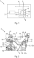
- FIG. 1 shows, in a highly schematic representation, an aircraft 1, preferably a helicopter, as an exemplary embodiment of the invention.
- the aircraft 1 has a drive motor 2 for generating a drive torque and a transmission 3 for translating the drive torque to at least one rotor 4 of the aircraft 1.
- the drive motor 2 is connected to the at least one rotor 4 via the gearbox 3.
- the transmission 3 has an oil system 5, which serves to lubricate and cool the transmission 3.
- the transmission 3 has an oil circuit through which a transmission oil circulates in the transmission 3 in a flow direction R1.
- An oil cooler device 6 is integrated into the oil circuit and serves to cool the oil.
- hot oil is conveyed from the transmission 3 to the oil cooler device 6, cooled and fed back to the transmission 3 as cooling oil.
- the oil system 5 has a distribution device 7, which is designed to distribute the cooling oil in the transmission 3.
- the cooling oil is distributed via the distribution device 7 in the transmission 3 and then fed back to the oil cooler device 6.
- the oil system 5 can have at least one oil pump, not shown, which is integrated into the oil circuit, for example in the flow direction R1 in front of the oil cooler device 6, to convey the oil.
- the oil system 5 also has a filter device 8 for filtering foreign particles from the cooling oil.
- the filter device 8 is arranged in the flow direction R1 between the oil cooler device 6 and the distribution device 7.
- FIG. 2 shows a section of the transmission 3 in a three-dimensional representation.
- the transmission 3 has a housing section 9, the housing section 9 having a hot oil channel 10 for guiding hot oil and a cooling oil channel 11 for guiding cooling oil.
- the hot oil channel 10 and the cooling oil channel 11 are formed by one or more bores arranged in the housing section 9.
- the oil system 5 has an oil cooler connection 12, via which the oil cooler device 6 can be connected to the hot oil channel 10 and the cooling oil channel 11.
- the oil system 5 has an outlet interface 12a and an inlet interface 12b, with the hot oil channel 10 being fluidly connected to the outlet interface 12a and the cooling oil channel 11 being fluidly connected to the inlet interface 12b.
- the exit interface 12a and the entry interface 12b are arranged on a common side of the housing section 9 and/or adjacent to one another.
- the oil cooler device 6 can be connected to the outlet interface 12a and the inlet interface 12b via corresponding connections, so that the hot oil flows into the oil cooler device 6 via the outlet interface 12a, is cooled and flows back into the transmission 3 as the cooling oil via the inlet interface 12b.
- the distribution device 7 has a collecting area 13 in which the cooling oil is collected and distributed via several distribution channels 14 in the transmission 3.
- the cooling oil channel 11 connects the inlet interface 12b with the collection area 13, with the distribution channels 14 directing the cooling oil from the collection area 13 to at least one cooling and lubrication point 15 in the transmission 3 in order to distribute the cooling oil in a targeted manner in the transmission 3.
- the filter device 8 is integrated into the cooling oil channel 11 between the inlet interface 12b and the distribution device 7, so that any foreign particles are filtered out of the cooling oil at an early stage, in particular before entering the collecting area 13.
- the Figure 3 shows the cooling channel 11 with the filter device 8 in a schematic sectional view.
- the cooling channel 11 has a first and a second channel section 16, 17, which are offset relative to one another in a height direction R2 and are fluidly connected to one another via a connecting section 18.
- a height offset is thus formed between the two channel sections 16, 17, with the first channel section 16 being lower than the second channel section 17 when the transmission 2 is in the intended installation position.
- the connecting section 18 is divided into a lower input area 19, an upper output area 20 and an intermediate area 21 lying between the input and output areas 20.
- the first channel section 16 connects the inlet interface 12b with the lower input area 19 and the second channel section 20 connects the upper output area 20 with the distribution device 7, in particular its collecting area 13.
- the connecting section 18 has a mounting opening 22, which is formed by a bore that is open to an outside of the transmission 2.
- the filter device 8 is mounted in the connecting section 18 via the mounting opening 22, with a main volume flow 23 of the cooling oil running from the first channel section 16 via the filter device 8 to the second channel section 17.
- the main volume flow 23 is deflected in the lower entrance area 19 and the upper exit area 20.
- the filter device 8 has a filter sieve 24.
- the oil coming from the oil cooler device 6 is passed over the filter screen 24, filtered and flows further to the collection area 13, where the filtered oil is distributed to the various distribution channels 14.
- the diameter of the distribution channels 14 is approximately 1 mm, which is why the foreign particles to be filtered should not exceed a maximum particle size of greater than 0.8 mm.
- the filter sieve 24 therefore has, for example, a mesh size of less than 0.6 mm in order to filter foreign particles with a diameter of more than 0.6 mm.
- the filter device 8 has a fastening device 25, wherein the filter screen 24 is fixed in a secure position in the intermediate region 21 via the fastening device 25.
- the fastening device 25 is designed, for example, as a closure plug, which is screwed into the upper output region 20 via the mounting opening 22 and seals the connecting section 18 to the outside in a fluid-tight manner.
- FIG. 4 shows a sectional view of the filter device 8 in an installation situation.
- the filter screen 24 is designed as a cylindrical screen insert with a central through opening 26, which passes through the filter screen 24 in the axial direction with respect to a main axis H.
- the main axis H is defined by a longitudinal axis of the filter screen 24.
- the fastening device 25 has a support section 27 which extends in the axial direction with respect to the main axis H in the direction of the filter screen 24.
- the support section 27 has a cylindrical shape, with the filter screen 24 being plugged onto the support section 27 via the through opening 26, preferably in a positive and/or non-positive manner.
- the filter screen 24 can be held in the intermediate space 21 exclusively via the support section 27.
- the filter screen 24 can also be additionally supported in the axial direction on a side opposite the fastening device 25 on the connecting section 21, so that the filter screen 24 is held in a form-fitting manner axially with respect to the main axis H.
- the fastening device 25 also has an oil guide section 28, which fluidly connects the through opening 26 to the second channel section 17 and serves to guide the cooling oil through the fastening device 25, in particular in the upper output region 20.
- the oil guide section 28 is inserted coaxially into the support section 27 and passes through the closure plug in the direction of the second channel section 17.
- the filter device 8 also has a bypass 40, which fluidly connects a raw side and a clean side to one another, bypassing the filter sieve 24.
- the raw side is defined by the side of the filter screen 24 on which the cooling oil is present unfiltered.
- the clean side is defined by the side of the filter screen 24 on which the cooling oil is filtered.
- the bypass 40 is formed by the through opening 26, the bypass 40 being switchable between a blocking state and a release state depending on a flow resistance of the filter screen 24.
- filter device 8 has a valve device 31 for controlling the flow through bypass 40.
- the valve device 31 includes a guide sleeve 29 with at least one bypass opening 30 as well as a valve element 32 and a spring element 33, which are arranged within the guide sleeve 29.
- the guide sleeve 29 is mounted in the through opening 26 at the end, in particular on the side of the entrance area 19.
- the valve element 32 is adjustable between a blocking position S and a release position F, with the valve element 32 blocking the bypass opening 30 in the blocking position S and at least partially releasing it in the release position F.
- the spring element 33 is supported in the axial direction on the one hand on the sleeve 30 and on the other hand on the valve element 32, the spring element 33 applying a spring force to the valve element in the direction of the blocking position S and pressing it into a valve seat.
- the Figures 5 to 7 each show the filter device 8 according to Figure 4 in different operating states of a filter operation.
- the filter device 8 additionally has a display device 34, which is designed to display a degree of contamination of the filter sieve 24.
- the display device 34 is designed as a differential pressure display, with the display device 34 indicating contamination of the filter screen 24 based on a predetermined differential pressure between the raw side and the clean side.
- the display device 34 has an indicator pin 35 and a control piston 36, which are arranged to be movable relative to one another in the axial direction in relation to the main axis H in a guide section 37 of the fastening device 25.
- the indicator pin 35 can be adjusted between a basic position G and a display position A, the indicator pin 35 being completely retracted into the guide section 37 in the basic position G, as shown in FIG. 5, and in the display position A, as shown in FIG Figures 6 and 7 shown, is at least partially extended from the guide section 37.
- the control piston 36 has a magnet, the indicator pin 35 being ferromagnetic and held in the basic position G by the magnet.
- the guide section 37 is fluidly connected on the one hand to the oil guide section 28 or the clean side and on the other hand via a secondary flow channel 38 to the intermediate space 21 or the raw side.
- the main volume flow 23 runs from the first channel section 16 via the filter screen 24 to the second channel section 17, with entrained foreign particles being filtered out of the cooling oil.
- the main volume flow 23 runs from the first channel section 16 via the filter screen 24 into the through hole 26 and via the oil guide section 28 to the second channel section 17.
- a secondary volume flow 39 runs from the intermediate region 21 via the secondary flow channel 38 into the guide section 37.
- the flow resistance of the filter screen 24 increases proportionally to its degree of contamination, so that the pressure on the raw side increases and decreases on the clean side.
- the control piston 36 is displaced axially in the direction of the oil guide section 28, whereby the attractive force between the magnet and the indicator pin 35 is reduced, so that the indicator pin 35 is moved in the direction of the display position A and contamination of the filter sieve 24 is indicated.
- the filter device 8 thus increases the operational reliability of the transmission 3 by filtering out foreign particles from the cooling oil at an early stage and at the same time ensuring an adequate supply of oil to the transmission components when the degree of contamination of the filter screen 24 increases.
Landscapes
- Engineering & Computer Science (AREA)
- General Engineering & Computer Science (AREA)
- Mechanical Engineering (AREA)
- General Details Of Gearings (AREA)
Claims (11)
- Système d'huile (5) pour une boîte de vitesses (3),avec un canal d'huile chaude (10) pour guider de l'huile chaude,avec un canal d'huile de refroidissement (11) pour guider de l'huile de refroidissement,avec un dispositif de distribution (7) pour une distribution de l'huile de refroidissement dans la boîte de vitesses (3), le dispositif de distribution (7) étant relié de manière fluidique au canal d'huile de refroidissement (11),avec un raccord de refroidisseur d'huile (12) pour raccorder un dispositif refroidisseur d'huile (6), dans lequel le raccord de refroidisseur d'huile (12) présente une interface de sortie (12a) communiquant avec le canal d'huile chaude (10) pour la sortie de l'huile chaude à partir de la boîte de vitesses (3) et une interface d'entrée (12b) communiquant avec le canal d'huile de refroidissement (11) pour l'entrée de l'huile de refroidissement dans la boîte de vitesse (3),avec un dispositif filtrant (8) agencé entre le dispositif de distribution (7) et l'interface d'entrée (12b) pour filtrer les particules étrangères présentes dans l'huile de refroidissement, dans lequel le dispositif filtrant (8) présente un tamis filtrant (24), dans lequel le tamis filtrant (24) est agencé dans le canal d'huile de refroidissement (11), dans lequel le dispositif filtrant (8) présente une dérivation (40), dans lequel la dérivation (40) peut être commutée entre un état de blocage et un état de libération en fonction d'une résistance à l'écoulement, dans lequel le dispositif filtrant (8) présente un dispositif de vanne (31) pour commander un écoulement à travers la dérivation(40), dans lequel le dispositif de vanne (31) commute automatiquement l'état de blocage et l'état de libération en cas de modification de la résistance à l'écoulement,caractérisé en ce que
le tamis filtrant (24) présente une ouverture de passage centrale (26) pour former la dérivation (40), le dispositif de vanne (31) étant monté côté entrée dans l'ouverture de passage (26). - Système d'huile (5) selon la revendication 1, caractérisé en ce que le tamis filtrant (24) est réalisé sous la forme d'un tamis grossier d'une largeur de maille inférieure à 0,8 mm.
- Système d'huile (5) selon la revendication 1 ou 2, caractérisé en ce que le canal d'huile de refroidissement (11) présente une première et une seconde section de canal (16, 17), dans lequel la première section de canal (16) est reliée de manière fluidique à l'interface d'entrée (12b) et la seconde section de canal (17) au dispositif de distribution (7), dans lequel les première et seconde sections de canal (16, 17) sont décalées l'une par rapport à l'autre et sont reliées de manière fluidique l'une à l'autre par une section de liaison (18), dans lequel le dispositif filtrant (8) est disposé dans la section de liaison (18).
- Système d'huile (5) selon la revendication 3, caractérisé en ce que la section de liaison (18) présente une zone d'entrée (19) et une zone de sortie (20), dans lequel la première section de canal (16) se termine dans la zone d'entrée (19) et la seconde section de canal (17) se termine dans la zone de sortie (20), dans lequel le dispositif filtrant (8) est agencé dans une zone intermédiaire (21) entre la zone d'entrée (19) et la zone de sortie (20).
- Système d'huile (5) selon la revendication 3 ou 4, caractérisé en ce que la section de liaison (18) présente une ouverture de montage (22) pouvant être fermée pour le montage du dispositif filtrant (8), dans lequel le dispositif filtrant (8) peut être monté et/ou est monté dans la section de liaison (18) via l'ouverture de montage (22).
- Système d'huile (5) selon l'une quelconque des revendications 4 à 5, caractérisé en ce que le dispositif filtrant (8) présente un dispositif de fixation (25) pour fixer le tamis filtrant (24), le tamis filtrant (24) étant maintenu de manière fiable dans la section de liaison (18) par le dispositif de fixation (25).
- Système d'huile (5) selon la revendication 6, caractérisé en ce que le dispositif de fixation (25) est réalisé sous la forme d'un bouchon de fermeture pouvant être monté dans l'ouverture de montage (22), qui ferme l'ouverture de montage (22) de manière étanche aux fluides.
- Système d'huile (5) selon l'une quelconque des revendications précédentes, caractérisé en ce que le dispositif filtrant (8) présente un dispositif d'affichage (34), le dispositif d'affichage (34) étant conçu pour afficher un degré de contamination du dispositif filtrant (8) en fonction d'une résistance à l'écoulement.
- Système d'huile (5) selon les revendications 6 et 8, caractérisé en ce que le dispositif d'affichage (34) est intégré dans le dispositif de fixation (25).
- Boîte de vitesses (3) pour la transmission d'un couple d'entraînement d'un moteur d'entraînement (2) à au moins un rotor (4) d'un aéronef (1), caractérisée par un système d'huile (5) selon l'une quelconque des revendications précédentes.
- Aéronef (1) doté du système d'huile (5) selon l'une quelconque des revendications 1 à 13, et/ou de la boîte de vitesses (3) selon la revendication 10.
Applications Claiming Priority (1)
| Application Number | Priority Date | Filing Date | Title |
|---|---|---|---|
| DE102021201491.7A DE102021201491A1 (de) | 2021-02-17 | 2021-02-17 | Ölsystem für ein Getriebe, Getriebe mit dem Ölsystem sowie Luftfahrzeug mit dem Ölsystem und/oder dem Getriebe |
Publications (2)
| Publication Number | Publication Date |
|---|---|
| EP4047244A1 EP4047244A1 (fr) | 2022-08-24 |
| EP4047244B1 true EP4047244B1 (fr) | 2023-11-22 |
Family
ID=80682746
Family Applications (1)
| Application Number | Title | Priority Date | Filing Date |
|---|---|---|---|
| EP22156769.6A Active EP4047244B1 (fr) | 2021-02-17 | 2022-02-15 | Système d'huile pour une transmission, transmission doté du système d'huile, ainsi qu'aéronef doté du système d'huile et/ou de la transmission |
Country Status (3)
| Country | Link |
|---|---|
| EP (1) | EP4047244B1 (fr) |
| DE (1) | DE102021201491A1 (fr) |
| PL (1) | PL4047244T3 (fr) |
Family Cites Families (8)
| Publication number | Priority date | Publication date | Assignee | Title |
|---|---|---|---|---|
| US4715244A (en) | 1986-07-17 | 1987-12-29 | Sundstrand Corporation | Self-scavenging gear box lubrication system |
| US4844202A (en) | 1987-09-28 | 1989-07-04 | Sundstrand Corporation | Lubrication system for and method of minimizing heat rejection in gearboxes |
| US5622051A (en) | 1995-06-26 | 1997-04-22 | Kanzaki Kokyukoki Mfg. Co., Ltd. | Axle driving apparatus with cooling tubing |
| JP2005291252A (ja) | 2004-03-31 | 2005-10-20 | Jatco Ltd | 自動変速機及びそのオイルクーラ |
| JP4427426B2 (ja) | 2004-10-01 | 2010-03-10 | ジヤトコ株式会社 | 変速機のオイルクーラ設置構造 |
| US20140001307A1 (en) | 2012-06-29 | 2014-01-02 | Bell Helicopter Textron Inc. | Aircraft Gearbox Lubrication System |
| US10415475B2 (en) | 2014-07-31 | 2019-09-17 | Sikorsky Aircraft Corporation | Gearbox oil cooling assembly |
| US10337607B2 (en) * | 2015-09-29 | 2019-07-02 | Allison Transmission, Inc. | Selectively controllable filtration system of a transmission and method thereof |
-
2021
- 2021-02-17 DE DE102021201491.7A patent/DE102021201491A1/de not_active Withdrawn
-
2022
- 2022-02-15 EP EP22156769.6A patent/EP4047244B1/fr active Active
- 2022-02-15 PL PL22156769.6T patent/PL4047244T3/pl unknown
Also Published As
| Publication number | Publication date |
|---|---|
| EP4047244A1 (fr) | 2022-08-24 |
| DE102021201491A1 (de) | 2022-08-18 |
| PL4047244T3 (pl) | 2024-05-20 |
Similar Documents
| Publication | Publication Date | Title |
|---|---|---|
| DE102005029964B4 (de) | Hydraulikkreislauf für ein Getriebe eines Kraftfahrzeuges | |
| EP3468826B1 (fr) | Système hydraulique d'actionnement d'un embrayage muni d'une lubrification à la demande de l'embrayage | |
| DE102007023953B4 (de) | Planetengetriebe mit einer Lamellenkupplung oder einer Lamellenbremse | |
| DE102016206745A1 (de) | Planetengetriebe | |
| EP1357990A1 (fr) | Dispositif filtrant | |
| DE102008029322A1 (de) | Schmiersystem und Ölkühler mit Nebenleitung | |
| DE102012209703B3 (de) | Behälter für einen Hydraulikkreislauf | |
| EP0376150A2 (fr) | Moteur à combustion interne avec deux circuits à liquide hydraulique | |
| DE102013019887A1 (de) | Filterelement und Filtersystem mit Nebenstromfilterung | |
| EP2482950A1 (fr) | Dispositif de filtration sous pression | |
| EP1350551B1 (fr) | Dispositif à vannes, particulièrement pour le circuit de graissage d'un moteur à combustion interne, comprennant une vanne à contourner et une vanne unidirectionale | |
| EP4047244B1 (fr) | Système d'huile pour une transmission, transmission doté du système d'huile, ainsi qu'aéronef doté du système d'huile et/ou de la transmission | |
| DE4342784A1 (de) | Hydraulikkreis | |
| EP2532848B1 (fr) | Dispositif de filtrage et de refroidissement | |
| DE102015210763A1 (de) | Ventileinrichtung für ein Kraftfahrzeug, insbesondere für einen Ölkreislauf eines Kraftfahrzeugs | |
| DE112008003607B4 (de) | Filtereinrichtung, insbesondere zur Filtration gasförmiger Fluide | |
| DE10110382A1 (de) | Schmierölkreis für eine Brennkraftmaschine | |
| EP1337308B1 (fr) | Module d'unites pour moteur a combustion interne | |
| WO2013178299A1 (fr) | Dispositif de filtration et procédé de fabrication d'un dispositif de filtration | |
| DE69718801T2 (de) | Filter- und kühlvorrichtung | |
| EP3516224A1 (fr) | Compresseur à vis pour véhicule utilitaire | |
| DE10344664B4 (de) | Vorrichtung zum Abtrennen von Verunreinigungen aus dem Schmieröl einer Brennkraftmaschine | |
| DE102021109876A1 (de) | Filter-Kühlkombinationseinheit eines Ölsystems | |
| DE102021002332A1 (de) | Kühlkreislauf für ein Kraftfahrzeug, insbesondere für einen Kraftwagen | |
| DE102020216241B4 (de) | Saugfilteranordnung für ein Getriebe eines Fahrzeuges |
Legal Events
| Date | Code | Title | Description |
|---|---|---|---|
| PUAI | Public reference made under article 153(3) epc to a published international application that has entered the european phase |
Free format text: ORIGINAL CODE: 0009012 |
|
| STAA | Information on the status of an ep patent application or granted ep patent |
Free format text: STATUS: THE APPLICATION HAS BEEN PUBLISHED |
|
| AK | Designated contracting states |
Kind code of ref document: A1 Designated state(s): AL AT BE BG CH CY CZ DE DK EE ES FI FR GB GR HR HU IE IS IT LI LT LU LV MC MK MT NL NO PL PT RO RS SE SI SK SM TR |
|
| STAA | Information on the status of an ep patent application or granted ep patent |
Free format text: STATUS: REQUEST FOR EXAMINATION WAS MADE |
|
| 17P | Request for examination filed |
Effective date: 20230223 |
|
| RAP3 | Party data changed (applicant data changed or rights of an application transferred) |
Owner name: AIRBUS HELICOPTERS TECHNIK GMBH |
|
| RBV | Designated contracting states (corrected) |
Designated state(s): AL AT BE BG CH CY CZ DE DK EE ES FI FR GB GR HR HU IE IS IT LI LT LU LV MC MK MT NL NO PL PT RO RS SE SI SK SM TR |
|
| GRAP | Despatch of communication of intention to grant a patent |
Free format text: ORIGINAL CODE: EPIDOSNIGR1 |
|
| STAA | Information on the status of an ep patent application or granted ep patent |
Free format text: STATUS: GRANT OF PATENT IS INTENDED |
|
| RIC1 | Information provided on ipc code assigned before grant |
Ipc: F16H 57/04 20100101AFI20230523BHEP |
|
| INTG | Intention to grant announced |
Effective date: 20230616 |
|
| P01 | Opt-out of the competence of the unified patent court (upc) registered |
Effective date: 20230530 |
|
| GRAS | Grant fee paid |
Free format text: ORIGINAL CODE: EPIDOSNIGR3 |
|
| GRAA | (expected) grant |
Free format text: ORIGINAL CODE: 0009210 |
|
| STAA | Information on the status of an ep patent application or granted ep patent |
Free format text: STATUS: THE PATENT HAS BEEN GRANTED |
|
| AK | Designated contracting states |
Kind code of ref document: B1 Designated state(s): AL AT BE BG CH CY CZ DE DK EE ES FI FR GB GR HR HU IE IS IT LI LT LU LV MC MK MT NL NO PL PT RO RS SE SI SK SM TR |
|
| REG | Reference to a national code |
Ref country code: GB Ref legal event code: FG4D Free format text: NOT ENGLISH |
|
| REG | Reference to a national code |
Ref country code: CH Ref legal event code: EP |
|
| REG | Reference to a national code |
Ref country code: DE Ref legal event code: R096 Ref document number: 502022000267 Country of ref document: DE |
|
| REG | Reference to a national code |
Ref country code: IE Ref legal event code: FG4D Free format text: LANGUAGE OF EP DOCUMENT: GERMAN |
|
| REG | Reference to a national code |
Ref country code: LT Ref legal event code: MG9D |
|
| REG | Reference to a national code |
Ref country code: NL Ref legal event code: MP Effective date: 20231122 |
|
| PG25 | Lapsed in a contracting state [announced via postgrant information from national office to epo] |
Ref country code: GR Free format text: LAPSE BECAUSE OF FAILURE TO SUBMIT A TRANSLATION OF THE DESCRIPTION OR TO PAY THE FEE WITHIN THE PRESCRIBED TIME-LIMIT Effective date: 20240223 |
|
| PG25 | Lapsed in a contracting state [announced via postgrant information from national office to epo] |
Ref country code: IS Free format text: LAPSE BECAUSE OF FAILURE TO SUBMIT A TRANSLATION OF THE DESCRIPTION OR TO PAY THE FEE WITHIN THE PRESCRIBED TIME-LIMIT Effective date: 20240322 |
|
| PG25 | Lapsed in a contracting state [announced via postgrant information from national office to epo] |
Ref country code: LT Free format text: LAPSE BECAUSE OF FAILURE TO SUBMIT A TRANSLATION OF THE DESCRIPTION OR TO PAY THE FEE WITHIN THE PRESCRIBED TIME-LIMIT Effective date: 20231122 |
|
| PG25 | Lapsed in a contracting state [announced via postgrant information from national office to epo] |
Ref country code: NL Free format text: LAPSE BECAUSE OF FAILURE TO SUBMIT A TRANSLATION OF THE DESCRIPTION OR TO PAY THE FEE WITHIN THE PRESCRIBED TIME-LIMIT Effective date: 20231122 |
|
| PG25 | Lapsed in a contracting state [announced via postgrant information from national office to epo] |
Ref country code: ES Free format text: LAPSE BECAUSE OF FAILURE TO SUBMIT A TRANSLATION OF THE DESCRIPTION OR TO PAY THE FEE WITHIN THE PRESCRIBED TIME-LIMIT Effective date: 20231122 |
|
| PG25 | Lapsed in a contracting state [announced via postgrant information from national office to epo] |
Ref country code: NL Free format text: LAPSE BECAUSE OF FAILURE TO SUBMIT A TRANSLATION OF THE DESCRIPTION OR TO PAY THE FEE WITHIN THE PRESCRIBED TIME-LIMIT Effective date: 20231122 Ref country code: LT Free format text: LAPSE BECAUSE OF FAILURE TO SUBMIT A TRANSLATION OF THE DESCRIPTION OR TO PAY THE FEE WITHIN THE PRESCRIBED TIME-LIMIT Effective date: 20231122 Ref country code: IS Free format text: LAPSE BECAUSE OF FAILURE TO SUBMIT A TRANSLATION OF THE DESCRIPTION OR TO PAY THE FEE WITHIN THE PRESCRIBED TIME-LIMIT Effective date: 20240322 Ref country code: GR Free format text: LAPSE BECAUSE OF FAILURE TO SUBMIT A TRANSLATION OF THE DESCRIPTION OR TO PAY THE FEE WITHIN THE PRESCRIBED TIME-LIMIT Effective date: 20240223 Ref country code: ES Free format text: LAPSE BECAUSE OF FAILURE TO SUBMIT A TRANSLATION OF THE DESCRIPTION OR TO PAY THE FEE WITHIN THE PRESCRIBED TIME-LIMIT Effective date: 20231122 Ref country code: BG Free format text: LAPSE BECAUSE OF FAILURE TO SUBMIT A TRANSLATION OF THE DESCRIPTION OR TO PAY THE FEE WITHIN THE PRESCRIBED TIME-LIMIT Effective date: 20240222 Ref country code: PT Free format text: LAPSE BECAUSE OF FAILURE TO SUBMIT A TRANSLATION OF THE DESCRIPTION OR TO PAY THE FEE WITHIN THE PRESCRIBED TIME-LIMIT Effective date: 20240322 |
|
| PG25 | Lapsed in a contracting state [announced via postgrant information from national office to epo] |
Ref country code: SE Free format text: LAPSE BECAUSE OF FAILURE TO SUBMIT A TRANSLATION OF THE DESCRIPTION OR TO PAY THE FEE WITHIN THE PRESCRIBED TIME-LIMIT Effective date: 20231122 Ref country code: RS Free format text: LAPSE BECAUSE OF FAILURE TO SUBMIT A TRANSLATION OF THE DESCRIPTION OR TO PAY THE FEE WITHIN THE PRESCRIBED TIME-LIMIT Effective date: 20231122 Ref country code: NO Free format text: LAPSE BECAUSE OF FAILURE TO SUBMIT A TRANSLATION OF THE DESCRIPTION OR TO PAY THE FEE WITHIN THE PRESCRIBED TIME-LIMIT Effective date: 20240222 Ref country code: LV Free format text: LAPSE BECAUSE OF FAILURE TO SUBMIT A TRANSLATION OF THE DESCRIPTION OR TO PAY THE FEE WITHIN THE PRESCRIBED TIME-LIMIT Effective date: 20231122 Ref country code: HR Free format text: LAPSE BECAUSE OF FAILURE TO SUBMIT A TRANSLATION OF THE DESCRIPTION OR TO PAY THE FEE WITHIN THE PRESCRIBED TIME-LIMIT Effective date: 20231122 |
|
| PG25 | Lapsed in a contracting state [announced via postgrant information from national office to epo] |
Ref country code: DK Free format text: LAPSE BECAUSE OF FAILURE TO SUBMIT A TRANSLATION OF THE DESCRIPTION OR TO PAY THE FEE WITHIN THE PRESCRIBED TIME-LIMIT Effective date: 20231122 |
|
| PG25 | Lapsed in a contracting state [announced via postgrant information from national office to epo] |
Ref country code: CZ Free format text: LAPSE BECAUSE OF FAILURE TO SUBMIT A TRANSLATION OF THE DESCRIPTION OR TO PAY THE FEE WITHIN THE PRESCRIBED TIME-LIMIT Effective date: 20231122 |
|
| PG25 | Lapsed in a contracting state [announced via postgrant information from national office to epo] |
Ref country code: SK Free format text: LAPSE BECAUSE OF FAILURE TO SUBMIT A TRANSLATION OF THE DESCRIPTION OR TO PAY THE FEE WITHIN THE PRESCRIBED TIME-LIMIT Effective date: 20231122 |
|
| PG25 | Lapsed in a contracting state [announced via postgrant information from national office to epo] |
Ref country code: SM Free format text: LAPSE BECAUSE OF FAILURE TO SUBMIT A TRANSLATION OF THE DESCRIPTION OR TO PAY THE FEE WITHIN THE PRESCRIBED TIME-LIMIT Effective date: 20231122 Ref country code: SK Free format text: LAPSE BECAUSE OF FAILURE TO SUBMIT A TRANSLATION OF THE DESCRIPTION OR TO PAY THE FEE WITHIN THE PRESCRIBED TIME-LIMIT Effective date: 20231122 Ref country code: RO Free format text: LAPSE BECAUSE OF FAILURE TO SUBMIT A TRANSLATION OF THE DESCRIPTION OR TO PAY THE FEE WITHIN THE PRESCRIBED TIME-LIMIT Effective date: 20231122 Ref country code: EE Free format text: LAPSE BECAUSE OF FAILURE TO SUBMIT A TRANSLATION OF THE DESCRIPTION OR TO PAY THE FEE WITHIN THE PRESCRIBED TIME-LIMIT Effective date: 20231122 Ref country code: DK Free format text: LAPSE BECAUSE OF FAILURE TO SUBMIT A TRANSLATION OF THE DESCRIPTION OR TO PAY THE FEE WITHIN THE PRESCRIBED TIME-LIMIT Effective date: 20231122 Ref country code: CZ Free format text: LAPSE BECAUSE OF FAILURE TO SUBMIT A TRANSLATION OF THE DESCRIPTION OR TO PAY THE FEE WITHIN THE PRESCRIBED TIME-LIMIT Effective date: 20231122 |
|
| REG | Reference to a national code |
Ref country code: DE Ref legal event code: R097 Ref document number: 502022000267 Country of ref document: DE |
|
| PLBE | No opposition filed within time limit |
Free format text: ORIGINAL CODE: 0009261 |
|
| STAA | Information on the status of an ep patent application or granted ep patent |
Free format text: STATUS: NO OPPOSITION FILED WITHIN TIME LIMIT |
|
| PG25 | Lapsed in a contracting state [announced via postgrant information from national office to epo] |
Ref country code: MC Free format text: LAPSE BECAUSE OF FAILURE TO SUBMIT A TRANSLATION OF THE DESCRIPTION OR TO PAY THE FEE WITHIN THE PRESCRIBED TIME-LIMIT Effective date: 20231122 |
|
| PG25 | Lapsed in a contracting state [announced via postgrant information from national office to epo] |
Ref country code: LU Free format text: LAPSE BECAUSE OF NON-PAYMENT OF DUE FEES Effective date: 20240215 |
|
| PG25 | Lapsed in a contracting state [announced via postgrant information from national office to epo] |
Ref country code: SI Free format text: LAPSE BECAUSE OF FAILURE TO SUBMIT A TRANSLATION OF THE DESCRIPTION OR TO PAY THE FEE WITHIN THE PRESCRIBED TIME-LIMIT Effective date: 20231122 |
|
| 26N | No opposition filed |
Effective date: 20240823 |
|
| PG25 | Lapsed in a contracting state [announced via postgrant information from national office to epo] |
Ref country code: SI Free format text: LAPSE BECAUSE OF FAILURE TO SUBMIT A TRANSLATION OF THE DESCRIPTION OR TO PAY THE FEE WITHIN THE PRESCRIBED TIME-LIMIT Effective date: 20231122 Ref country code: LU Free format text: LAPSE BECAUSE OF NON-PAYMENT OF DUE FEES Effective date: 20240215 |
|
| REG | Reference to a national code |
Ref country code: BE Ref legal event code: MM Effective date: 20240229 |
|
| PG25 | Lapsed in a contracting state [announced via postgrant information from national office to epo] |
Ref country code: BE Free format text: LAPSE BECAUSE OF NON-PAYMENT OF DUE FEES Effective date: 20240229 |
|
| PG25 | Lapsed in a contracting state [announced via postgrant information from national office to epo] |
Ref country code: IE Free format text: LAPSE BECAUSE OF NON-PAYMENT OF DUE FEES Effective date: 20240215 |
|
| PG25 | Lapsed in a contracting state [announced via postgrant information from national office to epo] |
Ref country code: IE Free format text: LAPSE BECAUSE OF NON-PAYMENT OF DUE FEES Effective date: 20240215 Ref country code: BE Free format text: LAPSE BECAUSE OF NON-PAYMENT OF DUE FEES Effective date: 20240229 |
|
| PGFP | Annual fee paid to national office [announced via postgrant information from national office to epo] |
Ref country code: FR Payment date: 20250224 Year of fee payment: 4 Ref country code: PL Payment date: 20250129 Year of fee payment: 4 |
|
| PG25 | Lapsed in a contracting state [announced via postgrant information from national office to epo] |
Ref country code: CY Free format text: LAPSE BECAUSE OF FAILURE TO SUBMIT A TRANSLATION OF THE DESCRIPTION OR TO PAY THE FEE WITHIN THE PRESCRIBED TIME-LIMIT; INVALID AB INITIO Effective date: 20220215 |
|
| REG | Reference to a national code |
Ref country code: CH Ref legal event code: PL |
|
| PG25 | Lapsed in a contracting state [announced via postgrant information from national office to epo] |
Ref country code: FI Free format text: LAPSE BECAUSE OF FAILURE TO SUBMIT A TRANSLATION OF THE DESCRIPTION OR TO PAY THE FEE WITHIN THE PRESCRIBED TIME-LIMIT Effective date: 20231122 |
|
| PG25 | Lapsed in a contracting state [announced via postgrant information from national office to epo] |
Ref country code: CH Free format text: LAPSE BECAUSE OF NON-PAYMENT OF DUE FEES Effective date: 20250228 |
|
| PGFP | Annual fee paid to national office [announced via postgrant information from national office to epo] |
Ref country code: GB Payment date: 20260220 Year of fee payment: 5 |
|
| PGFP | Annual fee paid to national office [announced via postgrant information from national office to epo] |
Ref country code: DE Payment date: 20260218 Year of fee payment: 5 |
|
| PGFP | Annual fee paid to national office [announced via postgrant information from national office to epo] |
Ref country code: AT Payment date: 20260301 Year of fee payment: 5 |
|
| PGFP | Annual fee paid to national office [announced via postgrant information from national office to epo] |
Ref country code: IT Payment date: 20260224 Year of fee payment: 5 |
|
| PGFP | Annual fee paid to national office [announced via postgrant information from national office to epo] |
Ref country code: TR Payment date: 20260210 Year of fee payment: 5 |