EP4047276A1 - Rail de maintien pour tubes de chauffage au sol - Google Patents
Rail de maintien pour tubes de chauffage au sol Download PDFInfo
- Publication number
- EP4047276A1 EP4047276A1 EP22154498.4A EP22154498A EP4047276A1 EP 4047276 A1 EP4047276 A1 EP 4047276A1 EP 22154498 A EP22154498 A EP 22154498A EP 4047276 A1 EP4047276 A1 EP 4047276A1
- Authority
- EP
- European Patent Office
- Prior art keywords
- rail
- tube
- retaining rail
- longitudinal direction
- retaining
- Prior art date
- Legal status (The legal status is an assumption and is not a legal conclusion. Google has not performed a legal analysis and makes no representation as to the accuracy of the status listed.)
- Granted
Links
Images


Classifications
-
- F—MECHANICAL ENGINEERING; LIGHTING; HEATING; WEAPONS; BLASTING
- F24—HEATING; RANGES; VENTILATING
- F24D—DOMESTIC- OR SPACE-HEATING SYSTEMS, e.g. CENTRAL HEATING SYSTEMS; DOMESTIC HOT-WATER SUPPLY SYSTEMS; ELEMENTS OR COMPONENTS THEREFOR
- F24D3/00—Hot-water central heating systems
- F24D3/12—Tube and panel arrangements for ceiling, wall, or underfloor heating
- F24D3/14—Tube and panel arrangements for ceiling, wall, or underfloor heating incorporated in a ceiling, wall or floor
- F24D3/141—Tube mountings specially adapted therefor
-
- F—MECHANICAL ENGINEERING; LIGHTING; HEATING; WEAPONS; BLASTING
- F24—HEATING; RANGES; VENTILATING
- F24D—DOMESTIC- OR SPACE-HEATING SYSTEMS, e.g. CENTRAL HEATING SYSTEMS; DOMESTIC HOT-WATER SUPPLY SYSTEMS; ELEMENTS OR COMPONENTS THEREFOR
- F24D3/00—Hot-water central heating systems
- F24D3/12—Tube and panel arrangements for ceiling, wall, or underfloor heating
- F24D3/14—Tube and panel arrangements for ceiling, wall, or underfloor heating incorporated in a ceiling, wall or floor
- F24D3/141—Tube mountings specially adapted therefor
- F24D3/142—Tube mountings specially adapted therefor integrated in prefab construction elements
-
- F—MECHANICAL ENGINEERING; LIGHTING; HEATING; WEAPONS; BLASTING
- F24—HEATING; RANGES; VENTILATING
- F24D—DOMESTIC- OR SPACE-HEATING SYSTEMS, e.g. CENTRAL HEATING SYSTEMS; DOMESTIC HOT-WATER SUPPLY SYSTEMS; ELEMENTS OR COMPONENTS THEREFOR
- F24D13/00—Electric heating systems
- F24D13/02—Electric heating systems solely using resistance heating, e.g. underfloor heating
- F24D13/022—Electric heating systems solely using resistance heating, e.g. underfloor heating resistances incorporated in construction elements
- F24D13/024—Electric heating systems solely using resistance heating, e.g. underfloor heating resistances incorporated in construction elements in walls, floors, ceilings
-
- Y—GENERAL TAGGING OF NEW TECHNOLOGICAL DEVELOPMENTS; GENERAL TAGGING OF CROSS-SECTIONAL TECHNOLOGIES SPANNING OVER SEVERAL SECTIONS OF THE IPC; TECHNICAL SUBJECTS COVERED BY FORMER USPC CROSS-REFERENCE ART COLLECTIONS [XRACs] AND DIGESTS
- Y02—TECHNOLOGIES OR APPLICATIONS FOR MITIGATION OR ADAPTATION AGAINST CLIMATE CHANGE
- Y02B—CLIMATE CHANGE MITIGATION TECHNOLOGIES RELATED TO BUILDINGS, e.g. HOUSING, HOUSE APPLIANCES OR RELATED END-USER APPLICATIONS
- Y02B30/00—Energy efficient heating, ventilation or air conditioning [HVAC]
Definitions
- the invention relates to a retaining rail for surface heating pipes, which comprises two longitudinal profiles which run parallel to one another in the longitudinal direction of the rail and which together form a plurality of pipe receptacles which each extend transversely to the longitudinal direction of the rail and are open at the top, and with each pipe receptacle in the longitudinal direction of the rail from inwards into the pipe receptacles protruding locking lugs is limited.
- retaining rails for the pipelines carrying the heat transfer fluid are known in connection with the air conditioning of rooms using surface heating systems, the retaining rails together with the pipeline being embedded in a concrete casting compound to be hardened.
- the EP 2679923 B1 Retaining rails which comprise two longitudinal profiles which run parallel to one another in the longitudinal direction of the rails and which together form a plurality of tube receptacles which are open at the top and each extend transversely to the longitudinal direction of the rails.
- a disadvantage of such retaining rails is the fact that the liquid concrete casting compound is hardly distributed evenly during embedding due to the specified rail geometry, so that cavities or, in the worst case, stress cracks in the hardened concrete can form.
- the invention is therefore based on the object of designing a retaining rail of the type described at the outset in such a way that, despite simple manufacturing and assembly conditions, the formation of voids and stress cracks in the hardened concrete are largely avoided.
- the invention solves the problem in that the longitudinal profiles each have, on their side opposite the tube mounts, a profile section that runs continuously in a wave shape in the longitudinal direction of the rail and has a number of corrugated humps, which each form spacers for specifying a distance between the tube mounts and a room surface or formwork.
- the invention is based on the finding that the flow behavior of the poured concrete can be influenced in an advantageous manner if the profile section of the retaining rail assigned to the spacers runs continuously in a wavy manner, i.e. assumes a constant wave shape with wave humps and wave troughs, so that in particular corners or contours tapering to a point be avoided.
- the improved flow behavior when pouring the retaining rails means that the concrete pouring compound is distributed more homogeneously in the formwork used for pouring, so that ultimately stress cracks in the hardened concrete can be largely avoided.
- the wave humps form the spacers, with the wave humps each resting on the formwork in the region of the corresponding wave hump peaks during the casting process.
- the retaining rail according to the invention is preferably manufactured as a one-piece plastic component.
- the detents assigned to a respective pipe receptacle can in principle be formed by a profile cross connector which connects the two longitudinal profiles at a defined distance from one another, an even more homogeneous distribution of the concrete grouting compound can be achieved while at the same time saving rail material if each pipe receptacle in the longitudinal direction of the rail by exactly two profile cross connectors is limited, the each have a resilient detent protruding inwards into the tube receptacles.
- the profile cross-connectors are preferably such that the formation of a bearing surface underneath a pipe accommodated by the pipe receptacle is avoided, ie that area underneath the pipe remains free and the concrete grout can also flow into this free space.
- it can be provided in particular to connect the two longitudinal profiles running parallel in the longitudinal direction of the rail at a distance from one another exclusively via the profile cross-connector, i.e. not to connect the two longitudinal profiles via an additional longitudinal profile.
- the spacers formed by the corrugation hump each have a preferably cylindrical support body in the area of the corrugation hump apex.
- the support body can also have other cross-sectional shapes.
- the support body essentially forms a support disc. This means that the diameter of the spacer is large compared to its height.
- the longitudinal profiles have several fastening holes for fastening means, in particular for fastening the retaining rail to a formwork, on the tube receptacle side in the longitudinal direction of the rail.
- the axis of the fastening holes preferably runs both orthogonally to the longitudinal direction of the rail and orthogonally to the longitudinal direction of the pipe receptacle.
- a locking connector can be provided at a free end of the retaining rail for engaging behind a locking receptacle of an adjacent retaining rail in a form-fitting and non-positive manner, whereas on the opposite free end there is a locking receptacle that can be engaged behind in a form-fitting and non-positive manner by a locking connector of an adjacent retaining rail.
- the latching connector preferably has an essentially T-shaped head, with the latching receptacle correspondingly forming a T-profile. Holding rails according to the invention can thus be connected to one another in a simple manner by pushing them on top of one another transversely to the longitudinal direction of the rails and transversely to the longitudinal direction of the pipe receptacle.
- the retaining rails according to the invention can also be used in connection with fair-faced concrete, it is proposed that the retaining rail be made of a translucent plastic.
- the support rail therefore does not have its own color and is therefore no longer visible when the concrete has hardened.
- the functionality of the retaining rail according to the invention can be further increased if the longitudinal profiles on their side opposite the tube mounts include additional tube mounts open at the bottom, for example for capillary tubes, capillary tube mats and/or heating tubes equipped with an electric heater.
- additional tube mounts open at the bottom for example for capillary tubes, capillary tube mats and/or heating tubes equipped with an electric heater.
- the retaining rails according to the invention only guide capillary tube mats, so that the upper tube receptacles facing away from the room surface remain unoccupied.
- the additional tube receptacle is preferably arranged in a trough of the corrugated profile section.
- the tube receptacles can be formed by clamping arms attached to the longitudinal profiles and pointing downwards between two spacers.
- a retaining rail according to the invention can be equipped in particular with core heating tubes inserted in tube mounts and with surface heating tubes inserted in tube mounts which are open at the bottom.
- the core heating tubes are used to control the temperature of a concrete core in which the support rail is cast, in particular for heating in cold seasons and for cooling in warm seasons.
- the surface heating pipes which are arranged particularly close to the surface, can be used to emit low-energy radiant heat.
- the surface heating tubes used in tube receptacles which are open at the bottom can be capillary tubes, capillary tube mats and/or heating tubes equipped with an electric heater.
- the advantage of heating pipes equipped with an electric heater is that they can be operated directly with solar power if necessary.
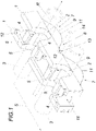
- a retaining rail according to the invention comprises two parallel longitudinal profiles 1 running at a distance from one another in the longitudinal direction S of the rail.
- the longitudinal profiles 1 together form a plurality of pipe receptacles 2 which are open at the top and extend transversely to the longitudinal direction S of the rail in a longitudinal direction R for receiving pipes, for accommodating surface heating pipes 3, for example.
- each tube mount 2 is delimited in the longitudinal direction S of the rail by exactly two profile cross-connectors 4 , each of which has a resilient latching lug 5 projecting inwards into the tube mounts 2 .
- Each tube mount 2 is thus delimited in the longitudinal direction S of the rails by detent lugs 5 protruding inwards into the tube mounts 2 .
- the two parallel longitudinal profiles 1 running at a distance from one another in the longitudinal direction S of the rails are connected transversely to the longitudinal direction S of the rails exclusively via the transverse profile connectors 4 .
- the longitudinal profiles 1 each have, on their side opposite the tube receptacles 2 , a profile section 6 which runs uniformly in a corrugated manner in the longitudinal direction S of the rails and has a plurality of corrugation humps 7 and a plurality of corrugation troughs 8 .
- the corrugation humps 7 each form spacers 9 for specifying a distance between the pipe receptacles 2 and a room surface or formwork 10 .
- the spacers 9 formed by the hump 7 each have a preferably cylindrical support body 11 in the region of the crest of the hump.
- the longitudinal profiles 1 comprise a plurality of fastening holes 12 for fastening means in the longitudinal direction S of the rails on the tube receptacle side.
- the hole axis of the fastening holes 12 runs orthogonally to the longitudinal direction S of the rail and orthogonally to the longitudinal direction R of the pipe socket.
- the longitudinal profiles also have, on their side opposite the tube mounts 2, additional tube mounts 13, which are open towards the bottom, for capillary tube mats 2 by surface heating pipes 14, in particular a tubular capillary or the like.
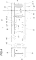
- a retaining rail is shown schematically which is embedded in a concrete mass of a ceiling, a wall or the like indicated by cross hatching. Any concrete reinforcement is mandatory, but not shown.
- the support rails each have a T-shaped locking connector 15 at a free end for engaging behind a locking receptacle 16 of an adjacent support rail in a positive and non-positive manner.
- the retaining rails each have, at the opposite free end, a snap-in receptacle 16 that can be gripped behind by a snap-in connector 15 of an adjacent retaining rail in a positive and non-positive manner.
- the snap-in connectors 15 have a substantially T-shaped head, with the snap-in receptacle 16 correspondingly forming a T-profile. Holding rails according to the invention can thus be connected to one another in a simple manner by pushing them on top of one another transversely to the longitudinal direction S of the rails and transversely to the longitudinal direction R of the pipe receiving means.
- the tube receptacles 13 are formed by clamping arms 17 which are attached to the longitudinal profiles 1 and point downwards between two spacers 9 .
- the clamping arms 17 are formed on the inside or bottom of the longitudinal profiles 1 and each form a cantilevered beam.
- Each pair of these clamp arms 17 in turn forms a tube mount 13, with the two clamp arm ends of each tube mount 13 being bent toward one another.
- Core heating pipes namely the surface heating pipes 3, and surface heating pipes 14, which are open at the bottom, are inserted into the pipe receptacles 2 of the holding rail.
- the in downward open Tube receptacles 13 used surface heating tubes 14 are in particular capillary tubes, capillary tube mats ( 2 u. 3 right) and/or with an electric heater ( 2 u. 3 left) equipped heating pipes.
Landscapes
- Engineering & Computer Science (AREA)
- Physics & Mathematics (AREA)
- Thermal Sciences (AREA)
- Chemical & Material Sciences (AREA)
- Combustion & Propulsion (AREA)
- Mechanical Engineering (AREA)
- General Engineering & Computer Science (AREA)
- Forms Removed On Construction Sites Or Auxiliary Members Thereof (AREA)
- Railway Tracks (AREA)
- Moulds, Cores, Or Mandrels (AREA)
- Supports For Pipes And Cables (AREA)
Priority Applications (1)
| Application Number | Priority Date | Filing Date | Title |
|---|---|---|---|
| HUU2300196U HU5930U (hu) | 2021-02-22 | 2022-02-01 | Tartósín felületfûtési csövekhez |
Applications Claiming Priority (1)
| Application Number | Priority Date | Filing Date | Title |
|---|---|---|---|
| ATGM50026/2021U AT17539U1 (de) | 2021-02-22 | 2021-02-22 | Halteschiene |
Publications (2)
| Publication Number | Publication Date |
|---|---|
| EP4047276A1 true EP4047276A1 (fr) | 2022-08-24 |
| EP4047276B1 EP4047276B1 (fr) | 2024-05-29 |
Family
ID=80221926
Family Applications (1)
| Application Number | Title | Priority Date | Filing Date |
|---|---|---|---|
| EP22154498.4A Active EP4047276B1 (fr) | 2021-02-22 | 2022-02-01 | Rail de maintien pour tubes de chauffage au sol |
Country Status (5)
| Country | Link |
|---|---|
| EP (1) | EP4047276B1 (fr) |
| AT (1) | AT17539U1 (fr) |
| DE (1) | DE202021106881U1 (fr) |
| HU (2) | HUE067845T2 (fr) |
| PL (1) | PL4047276T3 (fr) |
Cited By (2)
| Publication number | Priority date | Publication date | Assignee | Title |
|---|---|---|---|---|
| DE202024103594U1 (de) | 2023-07-06 | 2024-08-05 | Ke Kelit Gmbh | Halteschiene für Flächenheizungs- und/oder Flächenkühlungsrohre |
| EP4624810A1 (fr) | 2024-03-27 | 2025-10-01 | KE KELIT GmbH | Dispositif pour relier des rails de retenue |
Citations (5)
| Publication number | Priority date | Publication date | Assignee | Title |
|---|---|---|---|---|
| DE3101717A1 (de) * | 1981-01-21 | 1982-08-26 | Artus 5060 Bergisch Gladbach Feist | Aus metallischem flachmaterial bestehende schiene zum fixieren der heizrohre einer flaechenheizung |
| DE3108573A1 (de) * | 1981-03-06 | 1982-10-28 | Risse, Ernst, 4620 Castrop-Rauxel | Kunststoffprofilleiste mit an der oberseite befestigten rohraufnahmeelementen zum verlegen und fixieren des heizungsrohres einer fussbodenheizung |
| EP1619005A2 (fr) * | 2004-07-22 | 2006-01-25 | REHAU AG + Co | Procédé de fabrication d'un élément de construction préfabriqué avec des barres de renforcement en acier |
| DE102005039648A1 (de) * | 2004-08-18 | 2006-03-02 | BeKa-Heiz- und Kühlmatten GmbH | Positioniermittel, Verfahren zur Herstellung und zur Einbringung eines Positioniermittels |
| EP2679923B1 (fr) | 2012-06-27 | 2020-04-22 | KE KELIT Kunststoffwerk Gesellschaft m.b.H. | Dispositif de climatisation d'une pièce |
Family Cites Families (3)
| Publication number | Priority date | Publication date | Assignee | Title |
|---|---|---|---|---|
| DE50009278D1 (de) * | 2000-01-19 | 2005-02-24 | Sager Ag Duerrenaesch | Armierungs-Distanzhalter zum Verlegen einer Lage von Armierungseisen gegenüber einer Schalung für die Herstellung einer Betonkonstruktion |
| AT502685B1 (de) * | 2005-11-16 | 2007-05-15 | Wavin Bv | Deckensystem zur aufnahme von kühl- oder heizrohren |
| US8695943B2 (en) * | 2009-10-29 | 2014-04-15 | Flextherm Inc. | Wire installation tool for heating wire support meshing |
-
2021
- 2021-02-22 AT ATGM50026/2021U patent/AT17539U1/de unknown
- 2021-12-17 DE DE202021106881.7U patent/DE202021106881U1/de active Active
-
2022
- 2022-02-01 HU HUE22154498A patent/HUE067845T2/hu unknown
- 2022-02-01 EP EP22154498.4A patent/EP4047276B1/fr active Active
- 2022-02-01 HU HUU2300196U patent/HU5930U/hu unknown
- 2022-02-01 PL PL22154498.4T patent/PL4047276T3/pl unknown
Patent Citations (5)
| Publication number | Priority date | Publication date | Assignee | Title |
|---|---|---|---|---|
| DE3101717A1 (de) * | 1981-01-21 | 1982-08-26 | Artus 5060 Bergisch Gladbach Feist | Aus metallischem flachmaterial bestehende schiene zum fixieren der heizrohre einer flaechenheizung |
| DE3108573A1 (de) * | 1981-03-06 | 1982-10-28 | Risse, Ernst, 4620 Castrop-Rauxel | Kunststoffprofilleiste mit an der oberseite befestigten rohraufnahmeelementen zum verlegen und fixieren des heizungsrohres einer fussbodenheizung |
| EP1619005A2 (fr) * | 2004-07-22 | 2006-01-25 | REHAU AG + Co | Procédé de fabrication d'un élément de construction préfabriqué avec des barres de renforcement en acier |
| DE102005039648A1 (de) * | 2004-08-18 | 2006-03-02 | BeKa-Heiz- und Kühlmatten GmbH | Positioniermittel, Verfahren zur Herstellung und zur Einbringung eines Positioniermittels |
| EP2679923B1 (fr) | 2012-06-27 | 2020-04-22 | KE KELIT Kunststoffwerk Gesellschaft m.b.H. | Dispositif de climatisation d'une pièce |
Cited By (2)
| Publication number | Priority date | Publication date | Assignee | Title |
|---|---|---|---|---|
| DE202024103594U1 (de) | 2023-07-06 | 2024-08-05 | Ke Kelit Gmbh | Halteschiene für Flächenheizungs- und/oder Flächenkühlungsrohre |
| EP4624810A1 (fr) | 2024-03-27 | 2025-10-01 | KE KELIT GmbH | Dispositif pour relier des rails de retenue |
Also Published As
| Publication number | Publication date |
|---|---|
| EP4047276B1 (fr) | 2024-05-29 |
| HUE067845T2 (hu) | 2024-11-28 |
| PL4047276T3 (pl) | 2024-09-30 |
| AT17539U1 (de) | 2022-07-15 |
| DE202021106881U1 (de) | 2022-01-20 |
| HU5930U (hu) | 2025-09-28 |
Similar Documents
| Publication | Publication Date | Title |
|---|---|---|
| DE10040643C1 (de) | Verlegevorrichtung für Kühl- oder Heizmedium führende Rohre | |
| EP4047276B1 (fr) | Rail de maintien pour tubes de chauffage au sol | |
| EP2466028B1 (fr) | Composant avec des tuyeaux et procédé de fabrication d'un composant | |
| AT513069B1 (de) | Vorrichtung zum Klimatisieren eines Raumes | |
| DE102007055134A1 (de) | Baufertigelement mit Kühl-/Heizfunktion sowie Decken-Kühl-/Heizsystem | |
| EP1332318A1 (fr) | Plaque a poser modulaire utilisee dans des systemes de chauffage par plancher ou par mur et toles thermoconductrices associees | |
| EP0514684A1 (fr) | Plaque de montage pour des conduites flexibles. | |
| DE4108524C2 (de) | Vorrichtung zur Installation von Rohren oder Schläuchen | |
| EP1531306B1 (fr) | Plaque en plastique pour le montage de tubes dans lesquels circule un fluide | |
| DE10001839A1 (de) | Baustahlkonstruktion, Betonplattenelement mit integrierter Heiz- oder Kühlfunktion und Herstellungsverfahren | |
| DE4440790C1 (de) | Verfahren zur Herstellung von Kühldecken | |
| DE102014110843B4 (de) | Flächentemperierungselement sowie aus mehreren Flächentemperierungselementen bestehender Flächentemperierungsaufbau | |
| EP0994310A1 (fr) | Rail pour support de tuyaux | |
| DE102011114684B4 (de) | Rohrträger für ein Flächentemperiersystem in Betonböden, -wänden und -decken | |
| DE10253867B4 (de) | Vorrichtung zum Austausch von Wärme und/oder Kälte mit Feststoffen oder Feststoffgemischen | |
| AT17644U1 (de) | Halteschiene für Flächenheizungsrohre | |
| DE202012010492U1 (de) | Wärmedämmplatte | |
| DE4201552A1 (de) | Wandverkleidungselement | |
| DE10060971C1 (de) | Deckenelement | |
| DE102009037064B4 (de) | Absorber zum Erwärmen eines Fluids | |
| DE10251936A1 (de) | Trägerelement für ein Betonkerntemperierungsmodul | |
| DE202004015984U1 (de) | Gittermatte und Fertigelementdecke mit einer Gittermatte | |
| AT13655U1 (de) | Kühldeckenelement | |
| AT411914B (de) | Belagsplatte | |
| AT8931U1 (de) | Bodenaufbau mit auf stützen verlegten platten |
Legal Events
| Date | Code | Title | Description |
|---|---|---|---|
| PUAI | Public reference made under article 153(3) epc to a published international application that has entered the european phase |
Free format text: ORIGINAL CODE: 0009012 |
|
| STAA | Information on the status of an ep patent application or granted ep patent |
Free format text: STATUS: THE APPLICATION HAS BEEN PUBLISHED |
|
| AK | Designated contracting states |
Kind code of ref document: A1 Designated state(s): AL AT BE BG CH CY CZ DE DK EE ES FI FR GB GR HR HU IE IS IT LI LT LU LV MC MK MT NL NO PL PT RO RS SE SI SK SM TR |
|
| STAA | Information on the status of an ep patent application or granted ep patent |
Free format text: STATUS: REQUEST FOR EXAMINATION WAS MADE |
|
| 17P | Request for examination filed |
Effective date: 20230123 |
|
| RBV | Designated contracting states (corrected) |
Designated state(s): AL AT BE BG CH CY CZ DE DK EE ES FI FR GB GR HR HU IE IS IT LI LT LU LV MC MK MT NL NO PL PT RO RS SE SI SK SM TR |
|
| GRAP | Despatch of communication of intention to grant a patent |
Free format text: ORIGINAL CODE: EPIDOSNIGR1 |
|
| STAA | Information on the status of an ep patent application or granted ep patent |
Free format text: STATUS: GRANT OF PATENT IS INTENDED |
|
| INTG | Intention to grant announced |
Effective date: 20240306 |
|
| GRAS | Grant fee paid |
Free format text: ORIGINAL CODE: EPIDOSNIGR3 |
|
| GRAA | (expected) grant |
Free format text: ORIGINAL CODE: 0009210 |
|
| STAA | Information on the status of an ep patent application or granted ep patent |
Free format text: STATUS: THE PATENT HAS BEEN GRANTED |
|
| AK | Designated contracting states |
Kind code of ref document: B1 Designated state(s): AL AT BE BG CH CY CZ DE DK EE ES FI FR GB GR HR HU IE IS IT LI LT LU LV MC MK MT NL NO PL PT RO RS SE SI SK SM TR |
|
| REG | Reference to a national code |
Ref country code: CH Ref legal event code: EP |
|
| REG | Reference to a national code |
Ref country code: IE Ref legal event code: FG4D Free format text: LANGUAGE OF EP DOCUMENT: GERMAN |
|
| REG | Reference to a national code |
Ref country code: DE Ref legal event code: R096 Ref document number: 502022000940 Country of ref document: DE |
|
| REG | Reference to a national code |
Ref country code: NL Ref legal event code: FP |
|
| REG | Reference to a national code |
Ref country code: LT Ref legal event code: MG9D |
|
| PG25 | Lapsed in a contracting state [announced via postgrant information from national office to epo] |
Ref country code: IS Free format text: LAPSE BECAUSE OF FAILURE TO SUBMIT A TRANSLATION OF THE DESCRIPTION OR TO PAY THE FEE WITHIN THE PRESCRIBED TIME-LIMIT Effective date: 20240929 |
|
| PG25 | Lapsed in a contracting state [announced via postgrant information from national office to epo] |
Ref country code: BG Free format text: LAPSE BECAUSE OF FAILURE TO SUBMIT A TRANSLATION OF THE DESCRIPTION OR TO PAY THE FEE WITHIN THE PRESCRIBED TIME-LIMIT Effective date: 20240529 |
|
| REG | Reference to a national code |
Ref country code: SK Ref legal event code: T3 Ref document number: E 44726 Country of ref document: SK |
|
| PG25 | Lapsed in a contracting state [announced via postgrant information from national office to epo] |
Ref country code: HR Free format text: LAPSE BECAUSE OF FAILURE TO SUBMIT A TRANSLATION OF THE DESCRIPTION OR TO PAY THE FEE WITHIN THE PRESCRIBED TIME-LIMIT Effective date: 20240529 Ref country code: FI Free format text: LAPSE BECAUSE OF FAILURE TO SUBMIT A TRANSLATION OF THE DESCRIPTION OR TO PAY THE FEE WITHIN THE PRESCRIBED TIME-LIMIT Effective date: 20240529 |
|
| PG25 | Lapsed in a contracting state [announced via postgrant information from national office to epo] |
Ref country code: GR Free format text: LAPSE BECAUSE OF FAILURE TO SUBMIT A TRANSLATION OF THE DESCRIPTION OR TO PAY THE FEE WITHIN THE PRESCRIBED TIME-LIMIT Effective date: 20240830 |
|
| PG25 | Lapsed in a contracting state [announced via postgrant information from national office to epo] |
Ref country code: ES Free format text: LAPSE BECAUSE OF FAILURE TO SUBMIT A TRANSLATION OF THE DESCRIPTION OR TO PAY THE FEE WITHIN THE PRESCRIBED TIME-LIMIT Effective date: 20240529 |
|
| PG25 | Lapsed in a contracting state [announced via postgrant information from national office to epo] |
Ref country code: LV Free format text: LAPSE BECAUSE OF FAILURE TO SUBMIT A TRANSLATION OF THE DESCRIPTION OR TO PAY THE FEE WITHIN THE PRESCRIBED TIME-LIMIT Effective date: 20240529 |
|
| PG25 | Lapsed in a contracting state [announced via postgrant information from national office to epo] |
Ref country code: NO Free format text: LAPSE BECAUSE OF FAILURE TO SUBMIT A TRANSLATION OF THE DESCRIPTION OR TO PAY THE FEE WITHIN THE PRESCRIBED TIME-LIMIT Effective date: 20240829 Ref country code: LV Free format text: LAPSE BECAUSE OF FAILURE TO SUBMIT A TRANSLATION OF THE DESCRIPTION OR TO PAY THE FEE WITHIN THE PRESCRIBED TIME-LIMIT Effective date: 20240529 Ref country code: IS Free format text: LAPSE BECAUSE OF FAILURE TO SUBMIT A TRANSLATION OF THE DESCRIPTION OR TO PAY THE FEE WITHIN THE PRESCRIBED TIME-LIMIT Effective date: 20240929 Ref country code: HR Free format text: LAPSE BECAUSE OF FAILURE TO SUBMIT A TRANSLATION OF THE DESCRIPTION OR TO PAY THE FEE WITHIN THE PRESCRIBED TIME-LIMIT Effective date: 20240529 Ref country code: GR Free format text: LAPSE BECAUSE OF FAILURE TO SUBMIT A TRANSLATION OF THE DESCRIPTION OR TO PAY THE FEE WITHIN THE PRESCRIBED TIME-LIMIT Effective date: 20240830 Ref country code: FI Free format text: LAPSE BECAUSE OF FAILURE TO SUBMIT A TRANSLATION OF THE DESCRIPTION OR TO PAY THE FEE WITHIN THE PRESCRIBED TIME-LIMIT Effective date: 20240529 Ref country code: ES Free format text: LAPSE BECAUSE OF FAILURE TO SUBMIT A TRANSLATION OF THE DESCRIPTION OR TO PAY THE FEE WITHIN THE PRESCRIBED TIME-LIMIT Effective date: 20240529 Ref country code: BG Free format text: LAPSE BECAUSE OF FAILURE TO SUBMIT A TRANSLATION OF THE DESCRIPTION OR TO PAY THE FEE WITHIN THE PRESCRIBED TIME-LIMIT Effective date: 20240529 Ref country code: RS Free format text: LAPSE BECAUSE OF FAILURE TO SUBMIT A TRANSLATION OF THE DESCRIPTION OR TO PAY THE FEE WITHIN THE PRESCRIBED TIME-LIMIT Effective date: 20240829 |
|
| REG | Reference to a national code |
Ref country code: HU Ref legal event code: AG4A Ref document number: E067845 Country of ref document: HU |
|
| PG25 | Lapsed in a contracting state [announced via postgrant information from national office to epo] |
Ref country code: DK Free format text: LAPSE BECAUSE OF FAILURE TO SUBMIT A TRANSLATION OF THE DESCRIPTION OR TO PAY THE FEE WITHIN THE PRESCRIBED TIME-LIMIT Effective date: 20240529 |
|
| PG25 | Lapsed in a contracting state [announced via postgrant information from national office to epo] |
Ref country code: EE Free format text: LAPSE BECAUSE OF FAILURE TO SUBMIT A TRANSLATION OF THE DESCRIPTION OR TO PAY THE FEE WITHIN THE PRESCRIBED TIME-LIMIT Effective date: 20240529 |
|
| PG25 | Lapsed in a contracting state [announced via postgrant information from national office to epo] |
Ref country code: CZ Free format text: LAPSE BECAUSE OF FAILURE TO SUBMIT A TRANSLATION OF THE DESCRIPTION OR TO PAY THE FEE WITHIN THE PRESCRIBED TIME-LIMIT Effective date: 20240529 |
|
| PG25 | Lapsed in a contracting state [announced via postgrant information from national office to epo] |
Ref country code: RO Free format text: LAPSE BECAUSE OF FAILURE TO SUBMIT A TRANSLATION OF THE DESCRIPTION OR TO PAY THE FEE WITHIN THE PRESCRIBED TIME-LIMIT Effective date: 20240529 |
|
| PG25 | Lapsed in a contracting state [announced via postgrant information from national office to epo] |
Ref country code: SM Free format text: LAPSE BECAUSE OF FAILURE TO SUBMIT A TRANSLATION OF THE DESCRIPTION OR TO PAY THE FEE WITHIN THE PRESCRIBED TIME-LIMIT Effective date: 20240529 |
|
| PG25 | Lapsed in a contracting state [announced via postgrant information from national office to epo] |
Ref country code: SM Free format text: LAPSE BECAUSE OF FAILURE TO SUBMIT A TRANSLATION OF THE DESCRIPTION OR TO PAY THE FEE WITHIN THE PRESCRIBED TIME-LIMIT Effective date: 20240529 Ref country code: RO Free format text: LAPSE BECAUSE OF FAILURE TO SUBMIT A TRANSLATION OF THE DESCRIPTION OR TO PAY THE FEE WITHIN THE PRESCRIBED TIME-LIMIT Effective date: 20240529 Ref country code: EE Free format text: LAPSE BECAUSE OF FAILURE TO SUBMIT A TRANSLATION OF THE DESCRIPTION OR TO PAY THE FEE WITHIN THE PRESCRIBED TIME-LIMIT Effective date: 20240529 Ref country code: DK Free format text: LAPSE BECAUSE OF FAILURE TO SUBMIT A TRANSLATION OF THE DESCRIPTION OR TO PAY THE FEE WITHIN THE PRESCRIBED TIME-LIMIT Effective date: 20240529 Ref country code: CZ Free format text: LAPSE BECAUSE OF FAILURE TO SUBMIT A TRANSLATION OF THE DESCRIPTION OR TO PAY THE FEE WITHIN THE PRESCRIBED TIME-LIMIT Effective date: 20240529 |
|
| REG | Reference to a national code |
Ref country code: DE Ref legal event code: R097 Ref document number: 502022000940 Country of ref document: DE |
|
| PLBE | No opposition filed within time limit |
Free format text: ORIGINAL CODE: 0009261 |
|
| STAA | Information on the status of an ep patent application or granted ep patent |
Free format text: STATUS: NO OPPOSITION FILED WITHIN TIME LIMIT |
|
| PG25 | Lapsed in a contracting state [announced via postgrant information from national office to epo] |
Ref country code: SI Free format text: LAPSE BECAUSE OF FAILURE TO SUBMIT A TRANSLATION OF THE DESCRIPTION OR TO PAY THE FEE WITHIN THE PRESCRIBED TIME-LIMIT Effective date: 20240529 |
|
| 26N | No opposition filed |
Effective date: 20250303 |
|
| P01 | Opt-out of the competence of the unified patent court (upc) registered |
Free format text: CASE NUMBER: APP_17217/2025 Effective date: 20250409 |
|
| PG25 | Lapsed in a contracting state [announced via postgrant information from national office to epo] |
Ref country code: SE Free format text: LAPSE BECAUSE OF FAILURE TO SUBMIT A TRANSLATION OF THE DESCRIPTION OR TO PAY THE FEE WITHIN THE PRESCRIBED TIME-LIMIT Effective date: 20240529 |
|
| PG25 | Lapsed in a contracting state [announced via postgrant information from national office to epo] |
Ref country code: MC Free format text: LAPSE BECAUSE OF FAILURE TO SUBMIT A TRANSLATION OF THE DESCRIPTION OR TO PAY THE FEE WITHIN THE PRESCRIBED TIME-LIMIT Effective date: 20240529 |
|
| PG25 | Lapsed in a contracting state [announced via postgrant information from national office to epo] |
Ref country code: LU Free format text: LAPSE BECAUSE OF NON-PAYMENT OF DUE FEES Effective date: 20250201 |
|
| REG | Reference to a national code |
Ref country code: BE Ref legal event code: MM Effective date: 20250228 |
|
| PG25 | Lapsed in a contracting state [announced via postgrant information from national office to epo] |
Ref country code: BE Free format text: LAPSE BECAUSE OF NON-PAYMENT OF DUE FEES Effective date: 20250228 |
|
| PG25 | Lapsed in a contracting state [announced via postgrant information from national office to epo] |
Ref country code: IE Free format text: LAPSE BECAUSE OF NON-PAYMENT OF DUE FEES Effective date: 20250201 |
|
| REG | Reference to a national code |
Ref country code: CH Ref legal event code: U11 Free format text: ST27 STATUS EVENT CODE: U-0-0-U10-U11 (AS PROVIDED BY THE NATIONAL OFFICE) Effective date: 20260301 |
|
| PGFP | Annual fee paid to national office [announced via postgrant information from national office to epo] |
Ref country code: NL Payment date: 20260220 Year of fee payment: 5 |
|
| PGFP | Annual fee paid to national office [announced via postgrant information from national office to epo] |
Ref country code: HU Payment date: 20260211 Year of fee payment: 5 |
|
| PGFP | Annual fee paid to national office [announced via postgrant information from national office to epo] |
Ref country code: DE Payment date: 20260213 Year of fee payment: 5 |
|
| PGFP | Annual fee paid to national office [announced via postgrant information from national office to epo] |
Ref country code: AT Payment date: 20260301 Year of fee payment: 5 |
|
| PGFP | Annual fee paid to national office [announced via postgrant information from national office to epo] |
Ref country code: IT Payment date: 20260220 Year of fee payment: 5 |
|
| PGFP | Annual fee paid to national office [announced via postgrant information from national office to epo] |
Ref country code: FR Payment date: 20260224 Year of fee payment: 5 |
|
| PGFP | Annual fee paid to national office [announced via postgrant information from national office to epo] |
Ref country code: CH Payment date: 20260301 Year of fee payment: 5 |
|
| PGFP | Annual fee paid to national office [announced via postgrant information from national office to epo] |
Ref country code: PL Payment date: 20260122 Year of fee payment: 5 |
|
| PGFP | Annual fee paid to national office [announced via postgrant information from national office to epo] |
Ref country code: SK Payment date: 20260123 Year of fee payment: 5 |