EP4047577A1 - Système de sécurité / d'automatisation doté de dispositifs de détection communiquant dans le nuage - Google Patents
Système de sécurité / d'automatisation doté de dispositifs de détection communiquant dans le nuage Download PDFInfo
- Publication number
- EP4047577A1 EP4047577A1 EP22156553.4A EP22156553A EP4047577A1 EP 4047577 A1 EP4047577 A1 EP 4047577A1 EP 22156553 A EP22156553 A EP 22156553A EP 4047577 A1 EP4047577 A1 EP 4047577A1
- Authority
- EP
- European Patent Office
- Prior art keywords
- sensor
- panel
- control panel
- sensor device
- signal
- Prior art date
- Legal status (The legal status is an assumption and is not a legal conclusion. Google has not performed a legal analysis and makes no representation as to the accuracy of the status listed.)
- Pending
Links
Images


Classifications
-
- G—PHYSICS
- G08—SIGNALLING
- G08B—SIGNALLING SYSTEMS, e.g. PERSONAL CALLING SYSTEMS; ORDER TELEGRAPHS; ALARM SYSTEMS
- G08B25/00—Alarm systems in which the location of the alarm condition is signalled to a central station, e.g. fire or police telegraphic systems
- G08B25/14—Central alarm receiver or annunciator arrangements
-
- H—ELECTRICITY
- H04—ELECTRIC COMMUNICATION TECHNIQUE
- H04W—WIRELESS COMMUNICATION NETWORKS
- H04W84/00—Network topologies
- H04W84/18—Self-organising networks, e.g. ad-hoc networks or sensor networks
-
- G—PHYSICS
- G16—INFORMATION AND COMMUNICATION TECHNOLOGY [ICT] SPECIALLY ADAPTED FOR SPECIFIC APPLICATION FIELDS
- G16Y—INFORMATION AND COMMUNICATION TECHNOLOGY SPECIALLY ADAPTED FOR THE INTERNET OF THINGS [IoT]
- G16Y30/00—IoT infrastructure
-
- G—PHYSICS
- G16—INFORMATION AND COMMUNICATION TECHNOLOGY [ICT] SPECIALLY ADAPTED FOR SPECIFIC APPLICATION FIELDS
- G16Y—INFORMATION AND COMMUNICATION TECHNOLOGY SPECIALLY ADAPTED FOR THE INTERNET OF THINGS [IoT]
- G16Y40/00—IoT characterised by the purpose of the information processing
- G16Y40/30—Control
- G16Y40/35—Management of things, i.e. controlling in accordance with a policy or in order to achieve specified objectives
-
- H—ELECTRICITY
- H04—ELECTRIC COMMUNICATION TECHNIQUE
- H04W—WIRELESS COMMUNICATION NETWORKS
- H04W84/00—Network topologies
- H04W84/02—Hierarchically pre-organised networks, e.g. paging networks, cellular networks, WLAN [Wireless Local Area Network] or WLL [Wireless Local Loop]
-
- G—PHYSICS
- G08—SIGNALLING
- G08B—SIGNALLING SYSTEMS, e.g. PERSONAL CALLING SYSTEMS; ORDER TELEGRAPHS; ALARM SYSTEMS
- G08B25/00—Alarm systems in which the location of the alarm condition is signalled to a central station, e.g. fire or police telegraphic systems
- G08B25/01—Alarm systems in which the location of the alarm condition is signalled to a central station, e.g. fire or police telegraphic systems characterised by the transmission medium
- G08B25/10—Alarm systems in which the location of the alarm condition is signalled to a central station, e.g. fire or police telegraphic systems characterised by the transmission medium using wireless transmission systems
Definitions
- the present disclosure relates generally to security / automation systems and methods.
- An example implementation includes a method comprising receiving, by a processor of at least one sensor device, a signal from a sensor element of the at least one sensor device, wherein the sensor element is configured to sense a physical phenomenon, wherein the signal is indicative of the physical phenomenon as sensed by the sensor element.
- the method further includes determining, by the processor of the at least one sensor device, whether a level of the signal is indicative of an alarm condition.
- the method further includes using a cellular radio of the at least one sensor device to send a notification directly to a cloud system in response to the level of the signal being indicative of the alarm condition.
- Another example implementation includes an apparatus comprising at least one sensor device, the at least one sensor device comprising a memory and a processor communicatively coupled with the memory.
- the processor is configured to receive a signal from a sensor element of the at least one sensor device, wherein the sensor element is configured to sense a physical phenomenon, wherein the signal is indicative of the physical phenomenon as sensed by the sensor element.
- the processor is further configured to determine whether a level of the signal is indicative of an alarm condition.
- the processor is further configured to use a cellular radio of the at least one sensor device to send a notification directly to a cloud system in response to the level of the signal being indicative of the alarm condition.
- Another example implementation includes an apparatus comprising means for receiving, by a processor of at least one sensor device, a signal from a sensor element of the at least one sensor device, wherein the sensor element is configured to sense a physical phenomenon, wherein the signal is indicative of the physical phenomenon as sensed by the sensor element.
- the apparatus further includes means for determining, by the processor of the at least one sensor device, whether a level of the signal is indicative of an alarm condition.
- the apparatus further includes means for using a cellular radio of the at least one sensor device to send a notification directly to a cloud system in response to the level of the signal being indicative of the alarm condition.
- Another example implementation includes a computer-readable medium storing instructions executable by a processor of at least one sensor device, wherein the instructions, when executed, cause the processor to receive a signal from a sensor element of the at least one sensor device, wherein the sensor element is configured to sense a physical phenomenon, wherein the signal is indicative of the physical phenomenon as sensed by the sensor element.
- the instructions are further executable by the processor to cause the processor to determine whether a level of the signal is indicative of an alarm condition.
- the instructions are further executable by the processor to cause the processor to use a cellular radio of the at least one sensor device to send a notification directly to a cloud system in response to the level of the signal being indicative of the alarm condition.
- the one or more aspects comprise the features hereinafter fully described and particularly pointed out in the claims.
- the following description and the annexed drawings set forth in detail certain illustrative features of the one or more aspects. These features are indicative, however, of but a few of the various ways in which the principles of various aspects may be employed, and this description is intended to include all such aspects and their equivalents.
- Some security / automation systems provide an "All-in-One" control panel that includes hardware features, computing resources, software resources for implementing application intelligence, a user interface (UI), one or more radios, and external communication (e.g., with a monitoring station, a cloud system, etc.).
- UI user interface
- radios radios
- external communication e.g., with a monitoring station, a cloud system, etc.
- a control panel may include a user interface (e.g., processor and software resources), one or more radios (configured according to a protocol such as, e.g., PowerG, Z-wave, etc.) to wirelessly communicate with associated sensors and automation devices, interfaces to connect to wired sensors, application intelligence (e.g., processor and software resources), and communication of state to a remote application (according to a protocol such as, e.g., wireless fidelity (Wi-Fi), long term evolution (LTE), etc.).
- a user interface e.g., processor and software resources
- radios configured according to a protocol such as, e.g., PowerG, Z-wave, etc.
- application intelligence e.g., processor and software resources
- communication of state to a remote application accordinging to a protocol such as, e.g., wireless fidelity (Wi-Fi), long term evolution (LTE), etc.
- LTE category M Cat-M
- NB-IoT narrowband IoT
- LTE and Wi-Fi are becoming near ubiquitous, while inexpensive silicon for modern modulation schemes is allowing for improved performance and features for sensors.
- Some systems provide Wi-Fi with multiple bands, multiple-input multiple-output (MIMO) communication, mesh networking, and cheap Wi-Fi connected cameras.
- MIMO multiple-input multiple-output
- computing resources are becoming available in the form of cloud computing (e.g., a private or public cloud system that provides computing and storage resources via access over a network, e.g., Amazon Web Services (AWS)), software as a service (SaaS), on-demand computing for artificial intelligence (AI) and neural networking (e.g., user independent voice recognition, facial recognition), etc.
- AWS Amazon Web Services
- SaaS software as a service
- AI artificial intelligence
- neural networking e.g., user independent voice recognition, facial recognition
- voice UIs e.g., Amazon Alexa, Google, Siri, etc.
- the user interface of the deconstructed security / automation system may be provided as an application or "app" on a user device (e.g., on a user phone, tablet, computer, bring your own device (BYOD), etc.).
- the application intelligence of the deconstructed security / automation system may be moved to the cloud, where each customer has a virtual instance of the intelligence, and the instance runs in the cloud and communicates to the UI of a user device wherever the user is and on whatever device the user is using at a given time.
- the state of the deconstructed security / automation system may be communicated to a remote application (e.g., via Wi-Fi, LTE, etc.).
- the sensors of the deconstructed security / automation system and their associated radios provide reliable, 2-way, encrypted communication, and the sensors are low power and have long battery life.
- the hardware of the deconstructed security / automation system may be configured as a box which may be located in a closet or mounted on a wall (e.g., at a garage).
- the box may include a router with Wi-Fi MIMO, LTE, sensor radios, and Z-wave, and may be configured for improved antenna performance.
- the box may have a wide area network (WAN) port to plug into a cable or digital subscriber line (DSL) router.
- the UI of the deconstructed security / automation system may be provided by an app on a user device (e.g., a phone, a tablet, etc.).
- the intelligence of the deconstructed security / automation system e.g., functionality for maintaining state, deciding on actions based on state changes, etc.), voice recognition, facial recognition, etc. may be implemented in the cloud.
- the deconstructed security / automation system provides Wi-Fi MIMO, mesh, and real router performance. Accordingly, for example, the deconstructed security / automation system may provide whole home coverage, where mesh nodes are added as needed.
- the deconstructed security / automation system may also support Wi-Fi cameras with high resolution and high frame rate.
- the deconstructed security / automation system may allow for integration with other smart devices. For example, in an aspect, the deconstructed security / automation system may allow for integration with a smart television (TV) with an app that shows sensor changes and camera views in a pop-up window while watching TV.
- TV smart television
- the deconstructed security / automation system implements cloud computing and storage. Accordingly, the deconstructed security / automation system may provide virtually unlimited compute power that may be scaled up or down on demand. In this aspect, the deconstructed security / automation system may allow for voice recognition and/or facial recognition as seamless features that are available from any device with a microphone/camera. In this aspect, software updates to a user's virtual instance may be flexibly scheduled/performed in the cloud as needed (unlike conventional security / automation systems where updates are performed by a dealer). Various features of the deconstructed security / automation system may be readily turned on/off and billed for. This aspect may also provide cloud storage of images and videos from cameras associated with the system.
- the manufacturer or dealer for the deconstructed security / automation system may own the cellular contract with the customer.
- state information may go from the cloud of the deconstructed security / automation system to the servers or cloud of the company providing the monitoring service.
- the deconstructed security / automation system may provide a "home security / automation system" that is distributed and virtual.
- the deconstructed security / automation system is no longer limited to a single system and the sensors that are within radio range.
- the deconstructed security / automation system may include an aggregate of devices that are associated with an instance of intelligence running in the cloud.
- the device may be a part of the security / automation system.
- the system may include IoT devices with LTE cat-M or NB-IoT radios, and the IoT devices may be geographically located anywhere (e.g., the sensors in the system do not need to be within radio range of a control panel).
- multiple physical installations may be integrated into a single instance for monitoring and control.
- the system may provide one physical installation for a multi-unit building, and may then provide a separate virtual instance for each unit (e.g., provide partitions).
- the system may include a fully integrated control panel.
- the panel may include a color liquid crystal display (LCD) touchscreen interface that provides an intuitive graphical user interface (GUI) that allows for gesture-based user interaction (e.g., touch, swipe, etc.).
- GUI graphical user interface
- the panel may include a multi-core processor (e.g., four processor cores) that, while waiting for sensor state changes in the security / automation system, provides additional functionality as described with reference to various aspects herein (e.g., active panel microphones below).
- the panel may include a chipset (e.g., a Qualcomm Snapdragon chipset) that is configured to connect to the Internet via a Wi-Fi and/or cellular network.
- the chipset may include multiple radios for communication with premises security sensors/devices and/or premises automation sensors/devices.
- the chipset may include radios for Bluetooth, PowerG, Z-Wave, etc.
- the sensors/devices of the security / automation system may be wireless and may include, for example, one or more door/window sensors, motion sensors, carbon monoxide detectors, smoke detectors, flood sensors, etc.
- an app may run on a user smartphone or other mobile device (e.g., a tablet, a wearable, etc.).
- the user may use the app to remotely control various features of a premises security / automation system, for example, by a gesture on a user interface of the app (e.g., by a touch, swipe, etc.), or view images/video from a camera.
- the user who may be remote from a premises and who is planning to return to the premises, may use the app to remotely turn a porch light on or to remotely change a setting on a heating, ventilation, and air conditioning (HVAC) thermostat, so that the premises is comfortable when the user arrives at the premises.
- HVAC heating, ventilation, and air conditioning
- the panel may include one or more microphones that can be utilized to monitor the ambient noise in a protected area (e.g., a premises).
- the panel may include one or more software, hardware, and/or firmware modules that implement AI algorithms to recognize normal household voices and activity patterns. The user may put the panel into a monitoring mode where the panel sends an alert if the panel hears: (a) any voices in the protected area at a time when there typically is none, such as the middle of the night; (b) unknown voices in the protected area at a time when there typically is none, such as the middle of the night; (c) any unknown voices regardless of the time of day or activity period.
- the panel may include built-in processing power (e.g., the digital signal processing (DSP) implemented by a processor of a chipset in the panel, such as the Qualcomm Qualcomm smartphones) and built-in sensors/microphones to implement ambient noise-related event detection, without requiring a separate sensor/device to be installed at a premises.
- DSP digital signal processing
- the panel when the panel is triggered by any of the above conditions, the panel may send a corresponding notification, for example, to a mobile app through a cloud system.
- the panel when the panel is triggered, the panel may also use a built-in camera to take still images or a video clip and send the images or the video clip to the cloud system, which may then send the images or the video clip to a mobile app or web app on a user device (e.g., a smartphone) for visual verification of an event that triggered the panel.
- a user device e.g., a smartphone
- AI algorithms in the panel or in the cloud are modeled to scan for unidentified persons, smoke, or other events in the video clip for visual verification.
- a video clip that includes fifteen seconds before and fifteen seconds after the actual event is sent as notification to the cloud.
- the panel may be configured to detect events based on various noise detection models, such as continued noise level above a threshold, noise associated with multiple short sharp impacts (e.g., an intruder trying to kick down a door), gunshot detection, voice recognition to identify a request for assistance (e.g., a person falling down and asking for help), glass break detection, or detection of a particular standardized pattern of beeps such as the temporal-three pattern of a smoke detector going off (according to International Organization for Standardization (ISO) 8201 and American National Standards Institute (ANSI) / American Standards Association (ASA) S3.41 Temporal Pattern), the temporal-four pattern of a carbon monoxide detector going off, etc.
- various noise detection models such as continued noise level above a threshold, noise associated with multiple short sharp impacts (e.g., an intruder trying to kick down a door), gunshot detection, voice recognition to identify a request for assistance (e.g., a person falling down and asking for help), glass break detection, or detection of a particular standardized pattern
- the panel may use one or more built-in microphones to detect a fire event based on detecting the temporal-three pattern of a smoke detector alarm and/or the temporal-four pattern of a carbon monoxide detector alarm. Accordingly, the panel may implement fire detection functionality without requiring a wired or wireless connection with any fire detection sensors such as smoke detectors or carbon monoxide detectors. In one non-limiting aspect, the panel may voice annunciate fire or CO based on detecting these patterns.
- the panel may be configured to use one or more built-in microphones to perform occupancy detection (e.g., for senior care).
- the panel may use the built-in microphones to detect the ambient noise at a premises and analyze the ambient noise to determine activity of a senior (e.g., whether the senior got out of bed, operated a kitchen appliance, watched TV, etc.).
- the panel may report such activity of the senior to a remote user (e.g., to a relative of the senior) via an app on a smartphone of the user.
- voice commands can be given to the panel to activate emergency services.
- the panel uses built-in processing resources to implement AI algorithms for analyzing various discrete events and for determining what to do in response to a single detected event or in response to multiple detected events. Accordingly, an event may be a triggering point for taking certain actions.
- the AI algorithms may be downloaded to the panel from a server and may be customized for each individual panel.
- the panel may allow for integration of multiple events.
- the panel may detect multiple unrelated events, and then correlate/infer an integrated event from the multiple unrelated events using built-in AI algorithms.
- the panel may detect multiple front door open/close events reported by a door contact switch, while a Bluetooth radio of the panel may also detect multiple unrecognized devices/smartphones within range at the premises, and/or the panel may detect an unrecognized person by the AI algorithms running on imagery captured by the internal panel camera and/or by external cameras. The panel may then infer that a gathering is happening at the premises.
- the built-in microphone of the panel may continuously listen and may sample the ambient noise at regular intervals to detect audio events, and at the same time the panel may receive reports of other events via various built-in radios such as a Bluetooth radio.
- the panel has intelligence to correlate multiple concurrently happening events based on an AI model.
- the AI model may change depending on how a user intends to correlate various concurrently happening events, for example, based on a certain anomaly or a use case desired by the user.
- the AI model may be configured to take no action when a glass break event is detected while no other event is concurrently detected, but generate an alarm when a glass break event is detected concurrently with another event.
- the AI modeling and anomaly detection may be dynamically implemented and changed.
- the panel may use built-in processing power and one or more built-in microphones to virtually create and simulate one or more sensors.
- the panel may use one or more built-in microphones and added application to virtually create a fire detection sensor as described above (e.g., by detecting audio patterns of a smoke detector going off) or to virtually create a glass break detection sensor as described below.
- such virtually created and simulated sensors may either replace or augment respective dedicated physical sensors in a security / automation system of a premises.
- the panel itself may also be virtualized.
- the panel may use built-in microphones/sensors to virtualize and integrate various simulated sensors to take input in, and then the processing and intelligence applied to the input may be performed in a cloud system in communication with the panel.
- the panel may use one or more built-in microphones to detect an acoustic signature associated with one or more events.
- the panel may include one or more built-in microphones that can be utilized to monitor the ambient noise in a protected area and determine whether the ambient noise includes an acoustic signature associated with an event.
- the panel may receive sound waves and compare them to one or more of a plurality of known acoustic signatures associated with one or more events such as: a glass break, a gunshot, a dog barking, a person shouting, a smoke detector alarm, a voice, one or more keywords, or any other number of configurable sound events.
- the panel may perform glass break detection using one or more microphones.
- the panel may include one or more built-in microphones that can be utilized to monitor the ambient noises in a protected area to detect a glass break event.
- the panel may go into a low-power sleep mode, and may then wake up upon detecting a first sound from a probable glass break. After waking up, the panel may continue to analyze subsequent noises detected by the one or more microphone to determine if an actual glass break has occurred.
- a glass break event generates a sound with a particular acoustic signature which starts with a thump sound and then follows with a crashing noise.
- the panel may execute an application that, using the microphones in the panel, is configured to detect a glass break event by identifying a sequence of sounds corresponding to the acoustic signature of a glass break event.
- the panel has built-in processing power to execute software code to continually listen to the built-in microphones of the panel to detect a thump sound, and may then continue listening to the built-in microphones to determine if a crashing noise associated with a glass break event follows the thump sound.
- a control panel at a premises may include built-in processing power and built-in sensors / microphones to implement glass break detection functionality without requiring a separate glass break detection sensor / device to be installed at the premises.
- the sensors are short range devices that talk directly to a control panel using wired or wireless connections.
- a security / automation system includes sensors that talk directly to a cloud system, rather than going to the panel first.
- each sensor device may have a built-in cellular radio, so that the sensor device may use the cellular network to send information directly to a dedicated cloud.
- cloud communicative sensors remove the requirement for the panel to be a physical unit within a protected area.
- the panel may be a cloud-based application accessible on a fixed or mobile device that can be located and controlled at any geographic location.
- the cloud communicative sensors also allow the panel to become increasingly complex as the panel is no longer bound by physical hardware, software, or memory constraints. As technology improves, the panel application may also improve seamlessly.
- one or more sensors may use a cellular radio to communicate with a cloud system that supports a security / automation system.
- one or more sensors may each include a radio configured for communication according to the NB-IoT protocol.
- the NB-IoT protocol is designed and configured at hardware and at protocol level for small widely-deployed battery-powered devices that only need to communicate infrequently, such as a water meter that connects and reports on a daily basis.
- an NB-IoT radio may be included in a contact or PIR motion sensor (e.g., a door/window sensor, motion detector, etc.) such that the sensor may connect to a cellular network to send events and other information directly to the cloud.
- a security / automation system may include a virtualized control panel and may provide state management and intelligence in a dedicated cloud that can be hosted in a private or public cluster (e.g., AWS, private data center, etc.).
- any devices that are capable of establishing a direct cellular connection with the cloud may be configured as a part of the security / automation system, such as one or more NB-IoT sensors configured to communicate directly with the cloud using a cellular connection.
- the NB-IoT sensors of such a security / automation system may be located at various different geographic locations.
- a security system may include one or more cameras that use a cellular radio to send video clips to the cloud when the local AI algorithms detect unidentifiable persons or objects.
- a user may use a virtual control panel provided by a mobile app that is configured as an interface to the cloud.
- a virtual control panel provided by a mobile app that is configured as an interface to the cloud.
- the user may use a controlling application (app) on a user device to connect to the cloud and configure the security / automation system, e.g., manage and monitor sensors (e.g., turn sensors on or off), implement new sensors in the security / automation system, remove one or more sensors from the security / automation system, etc.
- such a virtualized control panel may allow for aggregating the security / automation system of multiple buildings together.
- a user may own two properties at two different physical locations, and may use a single virtualized control panel to monitor both locations.
- the virtualized control panel may allow for establishing a hierarchical security / automation system that includes several buildings. For example, at a highest hierarchical level, the virtualized control panel may be configured to indicate whether there are any issues reported at any of the geographical locations of buildings in a geographically distributed security / automation system, while a lower hierarchical level may provide more granularity and further details of issues reported to the security / automation system, such as a state, a city, a specific building, or a specific room where an issue was detected and reported.
- the virtualized control panel may allow for configuring a security / automation system that blankets a region. In an aspect, the virtualized control panel may allow for configuring a security / automation system that blankets the assets of a business. In an aspect, for example, the virtualized control panel may allow for configuring a security / automation system that includes a number of NB-IoT sensors installed at various geographically distributed public utility structures. In one non-limiting aspect, for example, the virtualized control panel may allow for configuring a security / automation system that includes one or more door/window contacts, and/or cellular cameras at the entrance kiosk of state parks, national grid substations, high voltage transmission towers, and/or other national infrastructures.
- the virtualized control panel may allow for configuring a security / automation system that includes a contact sensor at a mailbox, where the contact sensor communicates directly to the cloud to indicate at what times the mailbox has been opened. Accordingly, the security / automation system may send a notification to a user if the mailbox has been opened/accessed at an odd hour (e.g., between midnight and 5:00 am).
- an odd hour e.g., between midnight and 5:00 am.
- a control panel may include a built-in forward facing camera.
- the camera may be used to take a picture of the person who interacts with the panel to arm or disarm the panel and/or set-up the security / automation system and/or the panel.
- the camera may be used as a motion detector.
- the panel may delay taking alarm event pictures until motion is detected (e.g., by the panel or by a sensor in communication with the panel) or the local AI algorithm detects an unrecognized person. Accordingly, the panel may not waste memory storage space on meaningless pictures.
- the panel may detect an alarm event and trigger a siren and/or alert a monitoring center/homeowner.
- the panel may wait until motion is sensed/detected (e.g., by the panel or by a sensor in communication with the panel). Only after motion is sensed/detected, the panel may begin recording video or taking pictures to assist with the determination of who or what caused the alarm event. By waiting until motion is detected or the local AI algorithm detects an unrecognized person, the panel avoids taking unnecessary pictures and therefore retains more memory for pictures that have a greater likelihood of being material to the alarm event.
- the panel performs motion detection by comparing subsequent frames captured by a built-in camera in the panel.
- the built-in camera continuously captures images and/or video
- the panel performs frame-by-frame comparison of the images and/or video captured by the built-in camera to detect motion based on the amount of change in the pixels of subsequent frames.
- an optimized algorithm selectively samples for pixel changes in a frame. The algorithm may be calibrated to ignore pets and other unwanted objects.
- the panel starts recording the images/video captured by the built-in camera and sends the recorded images/video to the cloud.
- the cloud may then send the recorded images/video to a device of a user (e.g., a smartphone, a tablet, etc.) for viewing on an app running on the device of the user.
- a device of a user e.g., a smartphone, a tablet, etc.
- a user when a person disarms the panel, a user may be notified via an app on the user smartphone that the panel has been disarmed. The user may then use the app to remotely view an image or video of the person who disarmed the panel, where the image or video is taken by a built-in camera in the panel at the time the panel was disarmed or immediately after the panel was disarmed.
- the user may use the app to remotely view images and videos of the premises taken by a built-in camera of the panel.
- the user may use the app to remotely disarm the panel.
- control panel may include a built-in camera and may use the built-in camera to implement facial recognition.
- the panel may use the built-in camera to take video and/or images of the person and perform facial recognition based on the captured video and/or images to identify the person and determine whether the person is legitimate and authorized to arm or disarm the panel.
- the panel may use facial recognition in addition to another form of authentication (e.g., passcode, voice recognition, etc.) to perform multi-factor authentication and determine whether the person is legitimate and authorized to arm or disarm the panel.
- the panel may control one or more devices to operate according to a desired setting of the recognized person. For example, the panel may turn some lights on or off, turn music or radio on or off, adjust an HVAC temperature setting to a desired temperature, etc.
- the panel when the panel is next to a premises entry point such as a door, and a door contact sensor indicates to the panel that the door has been opened, the panel may use the built-in camera to take images of the person passing by and perform facial recognition, optionally together with voice recognition or other sensors, to determine whether the person is legitimate and authorized to enter the premises.
- the panel may use facial recognition, optionally together with voice recognition or other sensors, to determine how many people are present at a premises and whether known or unknown people are present at the premises.
- the panel may identify, via a built-in Bluetooth radio, that a number of Bluetooth devices are in range, which indicates a possibility of multiple people being present at the premises.
- the panel may then use facial recognition (via a built-in security camera), and optionally together with voice recognition (via a built-in microphone) to determine how many people are present at the premises and whether any of those people are legitimate and authorized to be at the premises.
- the panel may use a combination of the above to determine whether an unusual event is happening at the premises. For example, the panel may determine whether a number of unrecognized faces have passed by, whether a door has been opened and closed an unusually large number of times, whether an unusually large number of Bluetooth devices are in range, whether a noise sensor is indicating an unusually high amount of noise, whether an infra-red (IR) sensor is detecting an unusually large number of bodies, etc.
- IR infra-red
- the panel may use facial recognition for generating an alarm.
- the panel may initiate an alarm upon recognizing one or more specific individuals.
- control panel may implement AI functionality for tracking the applications and functions that a particular user typically invokes and/or is allowed to access. Accordingly, when the panel recognizes a person (e.g., through voice or facial recognition), the panel may bring up and display GUI features (e.g., buttons, icons, apps, etc.) that are typically invoked by and/or associated with the recognized person.
- GUI features e.g., buttons, icons, apps, etc.
- the panel may allow for restricting one or more features for one or more recognized user.
- the panel may allow for implementing parental control to limit access to certain features that are otherwise controllable via the panel.
- the panel may bring up personalized GUI features of a specific person based on facial recognition using a built-in camera in the panel, as described above.
- the AI algorithms for facial recognition are executed by a built-in multicore processor of the panel.
- the panel may send the images/video captured by the built-in camera to the cloud, and the AI algorithms for facial recognition are executed in the cloud.
- the cloud then sends the outcome of the facial recognition back to the panel. For example, if the cloud recognizes a person by applying facial recognition to images/video captured by the built-in camera of the panel, the cloud may send the identity of the recognized person to the panel.
- a security / automation system may include a window/door sensor that implements capacitive sensing to detect if a door or window is open or closed.
- a window/door sensor that implements capacitive sensing to detect if a door or window is open or closed.
- Such sensors are beneficial because the sensors do not use the conventional magnetic reed switches or other mechanical designs that require two separate pieces to be installed.
- some sensors used in security / automation systems for detecting whether a window/door is open or closed use a magnet and reed switch.
- the sensor containing the reed switch, or other magnetic sensing device is typically mounted on or in the window/door frame, and the magnet is mounted on the window/door.
- the magnet is in close proximity to the reed switch, keeping it closed.
- the magnet moves away from the reed switch, causing it to open.
- the sensor detects the change of state of the reed switch and transmits to a control panel, using wired or wireless communication.
- the window/door sensor it is desired to make the window/door sensor as small and inexpensive as possible. As small magnets with high magnetic field strength are a significant part of the overall sensor cost, it is advantageous to eliminate the magnet and use a different method to detect if the window/door is open or closed.
- some aspects sense the proximity of the window/door to the window/door frame without a magnet by measuring the capacitance between two conductive measurement points.
- the capacitance When the window/door is open, the capacitance will be lower compared to when the window/door is closed and physically close to the two measurement points.
- a microcontroller with appropriate circuitry may periodically measure the capacitance and then determine whether the window/door is open or closed.
- the sensing device may have a mode to self-calibrate when it is installed so it knows the difference between open and closed, thus accounting for differences in capacitance caused by different materials (such as wood, metal, masonry, etc.), different physical spacing between the sensor and the window/door, etc.
- the device may keep a long term history of any drift in values caused (for example) by changes in the moisture content of a wood window/door, changes in spacing caused by seasonal shifting or settling of construction, painting, etc.
- the window/door sensor includes an electrical circuit capable of measuring the capacitance between two closely-spaced metal elements, and the capacitance between the two metal elements changes depending on their proximity to the window/door.
- the metal elements can be implemented as patterns in the copper plating on a printed circuit board, or as separate metal elements connected to the measurement circuitry.
- the window/door sensor may be calibrated/trained during installation by opening and closing the window/door multiple times.
- the capacitive coupling of the sensor may be measured at different states of the window/door (e.g., fully open, fully closed, half open, etc.).
- the sensor threshold settings derived by calibration may vary depending on the material of the window/door (e.g., metal, wood, glass, etc.) and/or depending on the location/orientation of the sensor on the window/door and/or on the frame of the window/door.
- a control panel may include multiple primary speakers and a modular back speaker.
- the panel implements a modular speaker that may be attached or removed and which improves the sound qualities of the panel.
- the panel may use the modular speaker and one or more microphones to communicate with users through voice commands and responses, and may also use the modular speaker to broadcast other messages and music. Accordingly, the panel may function as a home appliance that communicates clearly and effectively.
- the panel may allow for audio as well as video user interaction.
- the panel may include one or more speakerphones and microphones.
- the panel may report an alarm to a monitoring center and may use a cellular interface of the control panel to establish a two-way voice call between the panel and the monitoring center.
- the monitoring center in response to a reported event, the monitoring center may make a voice call to the panel and ask a homeowner, via one or more speakerphones on the panel, about any emergencies existing at the premises and/or whether the homeowner requires assistance.
- One non-limiting aspect implements a diagnostic tool that tests, measures, and/or graphically maps the signal strength of the connection between one or more sensors and the control panel. Accordingly, a technician may do diagnostic analysis by using the panel itself, rather than needing to use additional signal strength meters, etc. This may speed up the installation of a security / automation system and/or provide a more robust installed security / automation system.
- the diagnostic tool may measure the received signal strength of wireless signals between one or more sensors and one or more radios in the panel (e.g., cellular or other radios).
- the diagnostic tool reads the received signal strength indicator (RSSI) of a radio.
- RSSI received signal strength indicator
- the diagnostic tool may listen to a radio and determine an instantaneous RSSI related to the background noise and plot the instantaneous RSSI on a graph over time. Accordingly, a technician/installer may use the graph to identify sources of noise in the environment that would interfere with the operation of the security / automation system.
- RSSI of sensor radios is sent to the cloud and historic signal strength data is maintained.
- a technician/installer may notice that operation of an electrical device is producing a signal that interferes with the signal transmitted by a sensor or camera that is trying to communicate with the panel.
- the technician may then adjust the installation of the panel, sensor, or camera and/or the electrical device to mitigate the interference.
- the graph may also display the average of the background noise by a first horizontal bar, and may also display a minimum acceptable sensor RSSI by a second horizontal bar that is above the first horizontal bar. Accordingly, the technician/installer may observe the graph over time and discern whether the RSSI of a sensor is above the second bar, thus being acceptable.
- various data points in the graph may be color-coded to indicate different signal quality categories, e.g., good signal, marginal signal, unreliable signal, etc.
- the technician/installer may reposition the sensor and/or reposition the panel until subsequent data points of the sensor are color-coded in the graph as being a good signal.
- repositioning the sensor may include changing the location and/or changing an orientation of the sensor.
- repositioning the panel may include changing a location and/or changing an orientation of the panel.
- a short range communication radio of the control panel may be used to determine whether a known device is in range, and the control panel may be automatically disarmed in response to the known device being in range.
- an entrance of a premises may also be unlocked in response to the known device being in range.
- the short range communication radio may be, for example, but is not limited to, a Bluetooth radio, a Bluetooth Low Energy (BLE) radio, a near-field communication (NFC) radio, etc.
- the panel when a panel recognizes a BLE signal from a known device, the panel is automatically disarmed. In an aspect, instead of arming/disarming the panel by determining the exact location of a user, the panel arms/disarms based on detecting that a user is within BLE range and that a BLE device of the user has been registered with the panel.
- a user smartphone may be paired with the panel in a premises, e.g., using a built-in Bluetooth radio in the panel.
- the built-in Bluetooth radio in the panel may detect that the user smartphone is within range.
- the panel may disarm and send a Z-Wave command to unlock the door and/or turn on the lights at the premises.
- a sensor on the back door may send a signal to the panel to indicate that the back door has been opened.
- the panel may, for example, chime and play an audio message such as "Back door opened!"
- the built-in Bluetooth radio in the panel may be used to pair new security or home automation sensors with the panel.
- pairing the sensor may be performed from a mobile phone app by scanning the sensor QR code and sending the sensor details to the panel using Bluetooth.
- a security / automation system 100 of a premises 102 may include various security devices 104 (e.g., sensors, cameras, etc.) installed/positioned throughout the premises 102.
- the security devices 104 may include a first cellular radio 116 for communicating directly (e.g., via a cellular network) with a cloud system 120 that implements at least some of the functionalities provided by the system 100, as described herein with reference to various aspects.
- a cloud system 120 may communicate with the cloud system 120 via another wired or wireless connection, for example, via a physical Ethernet connection.
- At least some of the security devices 104 may communicate with a control panel 106 that is physically installed at the premises 102.
- at least some of the security devices 104 may include one or more first other radios 118 (e.g., Bluetooth, PowerG, Z-Wave, Zigbee, etc.) for communicating with the panel 106 that includes one or more corresponding second other radios 134 (e.g., Bluetooth, PowerG, Z-Wave, etc.).
- first other radios 118 e.g., Bluetooth, PowerG, Z-Wave, Zigbee, etc.
- second other radios 134 e.g., Bluetooth, PowerG, Z-Wave, etc.
- at least some of the security devices 104 may communicate with the panel 106 via another wired or wireless connection, for example, via a physical Ethernet connection.
- the system 100 may be at least partially configured and/or controlled via a first UI 122 of the panel 106 to implement at least some of the functionalities described herein with reference to various aspects.
- the panel 106 may include one or more built-in cameras 126, one or more built-in microphones 128, and/or one or more built-in speakers 130 to implement at least some of the functionalities described herein with reference to various aspects.
- the panel 106 may include a second cellular radio 132 for communicating directly (e.g., via a cellular network) with the cloud system 120 to implements at least some of the functionalities provided by the system 100, as described herein with reference to various aspects.
- the panel 106 may communicate with the cloud system 120 via another wired or wireless connection, for example, via a physical Ethernet connection.
- the system 100 may be at least partially configured and/or controlled via a second UI 124 of a virtual control panel 110 provided via an app 112 executing on a user device 114 (e.g., a mobile device).
- the user device 114 may include a third cellular radio 136 for communicating directly (e.g., via a cellular network) with the cloud system 120 to implements at least some of the functionalities provided by the system 100, as described herein with reference to various aspects.
- the user device 114 may communicate with the cloud system 120 via another wired or wireless connection, for example, via a physical Ethernet connection.
- the user device 114 may also include one or more other radios 138 (e.g., Bluetooth, PowerG, Z-Wave, etc.).
- the panel 106 may include a removable back speaker 140 that may also provide support as a stand for placing the panel 106 on a surface such as a countertop or a desk.
- FIG. 3 includes a first non-limiting example of a GUI 300 of the diagnostic tool described above with reference to some aspects.
- a test/installer tool graph of the signal strength 306 changes from -50dBm to less than -90dBm as a sensor is progressively moved away from the control panel 106.
- the graph also displays the average of the background noise by a first horizontal bar 304, and also displays a minimum acceptable sensor RSSI by a second horizontal bar 302 that is above the first horizontal bar 304.
- FIG. 4 includes a second non-limiting example of a GUI 400 of the diagnostic tool described above with reference to some aspects.
- a graph shows a real-time noise floor measurement 402 at the control panel 106, indicating the interference caused by a switching power supply in an LED light fixture.
- the noise floor is slightly above -110dBm when the LED light is off, but jumps up to the neighborhood of -90dBm when the LED light is turned on, and drops down to -110dBm when the LED light is turned back off again.
- alternative or additional sources of noise / interference may include, for example, a microwave oven, a cordless phone, etc.
- FIG. 5 illustrates an example block diagram providing details of computing components in a computing device 1000 that may implement all or a portion of one or more components in a control panel, a cloud system, a sensor device, a user device (e.g., a smartphone, a tablet, a laptop computer, a desktop computer, etc.), or any other component described above.
- the computing device 1000 includes a processor 1002 which may be configured to execute or implement software, hardware, and/or firmware modules that perform any functionality described above with reference to one or more components in a control panel, a cloud system, a sensor device, a user device, or any other component described above.
- the processor 1002 may be configured to execute an active panel microphone functionality component 1012 to provide active panel microphone functionality, a glass break detection functionality component 1014 to provide glass break detection functionality, a cloud communicative sensor functionality component 1016 to provide cloud communicative sensor functionality, an alarm event picture functionality component 1018 to provide alarm event picture functionality, a facial recognition functionality component 1020 to provide facial recognition functionality, a GUI functionality component 1022 to provide GUI functionality, a diagnostic tool functionality component 1024 to provide diagnostic tool functionality, and/or a BLE disarming functionality component 1026 to provide functionality for using BLE for disarming, as described herein with reference to various aspects.
- an active panel microphone functionality component 1012 to provide active panel microphone functionality
- a glass break detection functionality component 1014 to provide glass break detection functionality
- a cloud communicative sensor functionality component 1016 to provide cloud communicative sensor functionality
- an alarm event picture functionality component 1018 to provide alarm event picture functionality
- a facial recognition functionality component 1020 to provide facial recognition functionality
- GUI functionality component 1022 to provide GUI functionality
- the processor 1002 may be a micro-controller and/or may include a single or multiple set of processors or multi-core processors. Moreover, the processor 1002 may be implemented as an integrated processing system and/or a distributed processing system.
- the computing device 1000 may further include a memory 1004, such as for storing local versions of applications being executed by the processor 1002, related instructions, parameters, etc.
- the memory 1004 may include a type of memory usable by a computer, such as random access memory (RAM), read only memory (ROM), tapes, flash drives, magnetic discs, optical discs, volatile memory, non-volatile memory, and any combination thereof. Additionally, the processor 1002 and the memory 1004 may include and execute an operating system executing on the processor 1002, one or more applications, display drivers, etc., and/or other components of the computing device 1000.
- the computing device 1000 may include a communications component 1006 that provides for establishing and maintaining communications with one or more other devices, parties, entities, etc., utilizing hardware, software, and services.
- the communications component 1006 may carry communications between components on the computing device 1000, as well as between the computing device 1000 and external devices, such as devices located across a communications network and/or devices serially or locally connected to the computing device 1000.
- the communications component 1006 may include one or more buses, and may further include transmit chain components and receive chain components associated with a wireless or wired transmitter and receiver, respectively, operable for interfacing with external devices.
- the computing device 1000 may include a data store 1008, which can be any suitable combination of hardware and/or software, that provides for mass storage of information, databases, and programs.
- the data store 1008 may be or may include a data repository for applications and/or related parameters not currently being executed by processor 1002.
- the data store 1008 may be a data repository for an operating system, application, display driver, etc., executing on the processor 1002, and/or one or more other components of the computing device 1000.
- the computing device 1000 may also include a user interface component 1010 operable to receive inputs from a user of the computing device 1000 and further operable to generate outputs for presentation to the user (e.g., via a display interface to a display device).
- the user interface component 1010 may include one or more input devices, including but not limited to a keyboard, a number pad, a mouse, a touch-sensitive display, a navigation key, a function key, a microphone, a voice recognition component, or any other mechanism capable of receiving an input from a user, or any combination thereof.
- the user interface component 1010 may include one or more output devices, including but not limited to a display interface, a speaker, a haptic feedback mechanism, a printer, any other mechanism capable of presenting an output to a user, or any combination thereof.
- the security / automation system 100 may include one or more cloud-communicative sensor devices 602, 604 (e.g., sensors, cameras, etc.) each including a sensor element 605, 607 and a built-in cellular radio 606, 608 and each being installed / positioned at a different geographical location 610, 612. Further details of the security / automation system 100 in FIG. 6 is described below with reference to FIG. 7 and FIG. 8 .
- cloud-communicative sensor devices 602, 604 e.g., sensors, cameras, etc.
- each including a sensor element 605, 607 and a built-in cellular radio 606, 608 each being installed / positioned at a different geographical location 610, 612. Further details of the security / automation system 100 in FIG. 6 is described below with reference to FIG. 7 and FIG. 8 .
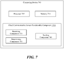
- computing device 700 may implement at least a portion of one or more components in FIGS. 1-6 above, such as all or at least a portion of a security device 104 in FIG. 1 , where the security device 104 may be or may include a sensor device 602, 604 in FIG. 6 .
- the computing device 700 may perform method 800 such as via execution of cloud communicative sensor functionality component 1016 by processor 705 and/or memory 710.
- computing device 700 may be configured to perform method 800 for performing an aspect of cloud communicative sensor functionality, as described herein.
- computing device 700, processor 705, and memory 710 may be the same or similar to computing device 1000, processor 1002, and memory 1004 as described above with respect to FIG. 5 .
- the method 800 includes receiving, by a processor of at least one sensor device, a signal from a sensor element of the at least one sensor device, wherein the sensor element is configured to sense a physical phenomenon, wherein the signal is indicative of the physical phenomenon as sensed by the sensor element.
- computing device 700, processor 705, memory 710, cloud communicative sensor functionality component 1016, and/or receiving component 735 may be configured to or may comprise means for receiving, by a processor of at least one sensor device, a signal from a sensor element of the at least one sensor device, wherein the sensor element is configured to sense a physical phenomenon, wherein the signal is indicative of the physical phenomenon as sensed by the sensor element.
- the receiving at block 802 may include the first sensor device 602 using the receiving component 735, such as but not limited to a wired or wireless receiver or transceiver or modem or communication interface, to receive a signal from the first sensor element 605 of the first sensor device 602, wherein the first sensor element 605 (which may be, for example, a door / window displacement detector, a motion detector, a smoke detector, etc.) is configured to sense a physical phenomenon (e.g., electromagnetic field intensity, infrared radiation, heat, smoke, etc.), wherein the signal is indicative of the physical phenomenon as sensed by the first sensor element 605.
- the first sensor element 605 which may be, for example, a door / window displacement detector, a motion detector, a smoke detector, etc.
- a physical phenomenon e.g., electromagnetic field intensity, infrared radiation, heat, smoke, etc.
- the receiving at block 802 may include the second sensor device 604 using the receiving component 735 to receive a signal from the second sensor element 607 of the second sensor device 604, wherein the second sensor element 607 (which may be, for example, a door / window displacement detector, a motion detector, a smoke detector, etc.) is configured to sense a physical phenomenon (e.g., electromagnetic field intensity, infrared radiation, heat, smoke, etc.), wherein the signal is indicative of the physical phenomenon as sensed by the second sensor element 607.
- each one of the first sensor device 602 or the second sensor device 604 may be a security device 104 as described above with reference to various implementations / aspects.
- the method 800 includes determining, by the processor of the at least one sensor device, whether a level of the signal is indicative of an alarm condition.
- computing device 700, processor 705, memory 710, cloud communicative sensor functionality component 1016, and/or determining component 740 may be configured to or may comprise means for determining, by the processor of the at least one sensor device, whether a level of the signal is indicative of an alarm condition.
- the determining at block 804 may include the first sensor device 602 using the determining component 740 to compare the level of the signal received from the first sensor element 605 of the first sensor device 602 against a threshold signal level, e.g., associated with an alarm condition, and determine whether the level of the signal received from the first sensor element 605 of the first sensor device 602 is indicative of an alarm condition (e.g., a door / window has been opened, smoke above a threshold has been detected, heat above a threshold has been detected, etc.).
- a threshold signal level e.g., associated with an alarm condition
- the determining at block 804 may include the second sensor device 604 using the determining component 740 to compare the level of the signal received from the second sensor element 607 of the second sensor device 604 against a signal level threshold and determine whether the level of the signal received from the second sensor element 607 of the second sensor device 604 is indicative of an alarm condition (e.g., a door / window has been opened, smoke above a threshold has been detected, heat above a threshold has been detected, etc.).
- an alarm condition e.g., a door / window has been opened, smoke above a threshold has been detected, heat above a threshold has been detected, etc.
- the method 800 includes using a cellular radio of the at least one sensor device to send a notification directly to a cloud system in response to the level of the signal being indicative of the alarm condition.
- computing device 700, processor 705, memory 710, cloud communicative sensor functionality component 1016, and/or sending component 745 may be configured to or may comprise means for using a cellular radio of the at least one sensor device to send a notification directly to a cloud system in response to the level of the signal being indicative of the alarm condition.
- the sending at block 806 may include the first sensor device 602 using the sending component 745 to send, via, for example, a transceiver chain and an antenna of the first sensor device cellular radio 606 of the first sensor device 602, a notification directly to the cloud system 120 in response to the level of the signal received from the first sensor element 605 of the first sensor device 602 being indicative of an alarm condition.
- the sending at block 806 may include the second sensor device 604 using the sending component 745 to send, via, for example, a transceiver chain and an antenna of the second sensor device cellular radio 608 of the second sensor device 604, a notification directly to the cloud system 120 in response to the level of the signal received from the second sensor element 607 of the second sensor device 604 being indicative of an alarm condition.
- any security devices 104 that are capable of establishing a direct cellular connection with the cloud system 120 may be configured as a part of the security / automation system 100.
- the first sensor device 602 may send status information in response to the signal received from the first sensor element 605 of the first sensor device 602. For example, an amount of current drawn by an air conditioner compressor may be indicative of impending failure and a call for maintenance.
- the second sensor device 604 may also provide similar functionality for sending status information instead of or in addition to an alarm condition.
- the cellular radio is operable according to NB-IoT protocol.
- the first sensor device cellular radio 606 and/or the second sensor device cellular radio 608 may each include a protocol stack operable according to NB-IoT protocol, for example, as defined by third generation partnership program "3GPP" technical specifications.
- the NB-IoT protocol is designed and configured at hardware and at protocol level for small widely-deployed battery-powered devices that only need to communicate infrequently, such as a water meter that connects and reports on a daily basis.
- an NB-IoT radio may be included in a contact or PIR motion sensor (e.g., a door / window displacement detector, a motion detector, etc.) such that the sensor may connect to a cellular network to send events and other information directly to the cloud system 120.
- a contact or PIR motion sensor e.g., a door / window displacement detector, a motion detector, etc.
- the at least one sensor device comprises at least one fire detection device.
- the first sensor device 602 and/or the second sensor device 604 may be or may include a fire detection device, such as a smoke detector or a carbon monoxide detector.
- a fire detection device such as a smoke detector or a carbon monoxide detector.
- one or more fire detection devices in the premises 102 may each include and use a cellular radio to communicate directly with the cloud system 120, where the cloud system 120 supports the security / automation system 100.
- the method 800 may further comprise communicating, by a virtual control panel, with the cloud system, to interact with or configure the at least one sensor device.
- the virtual control panel 110 may communicate with the cloud system 120, for example, via a cellular connection, over the Internet, etc., to interact with or to configure the first sensor device 602 and/or the second sensor device 604.
- the virtual control panel 110 may include but is not limited to one or more graphical user interfaces each associated with computer executable instructions for implementing one or more control functions of a control panel.
- a user may use a virtual control panel 110 that is configured as an interface to the cloud system 120.
- the user may use the virtual control panel 110 on the user device 114 to connect to the cloud system 120 and configure the security / automation system 100, e.g., manage and monitor sensors / security devices 104 (e.g., turn sensors on or off), implement new sensors / security devices 104 in the security / automation system 100, remove one or more sensors / security devices 104 from the security / automation system 100, etc.
- the virtual control panel 110 may provide state management and intelligence in the dedicated cloud system 120 that can be hosted in a private or public cluster (e.g., AWS, private data center, etc.).
- the virtual control panel is implemented as a cloud-based application executable on a user device.
- the virtual control panel 110 may be implemented as a cloud-based application (e.g., app 112) executable on the user device 114.
- the virtual control panel 110 may be provided by a mobile app 112 on a mobile user device 114.
- the user may use a controlling mobile application (app 112) on a mobile user device 114 to connect to the cloud system 120 and configure the security / automation system 100.
- the at least one sensor device comprises at least two sensor devices located at two or more different geographical locations.
- the first sensor device 602 is located at the first geographical location 610 while the second sensor device 604 is located at the second geographical location 612 that is different than the first geographical location 610 (e.g., located at a different building, city, town, state, etc.).
- one or more sensors devices in the security / automation system 100 may each include a radio configured for communication according to the NB-IoT protocol, and such NB-IoT sensors may be located at various different geographic locations.
- the virtual control panel 110 may allow for aggregating the security / automation system 100 of multiple buildings together.
- a user may own two properties at two different physical locations, and may use a single virtualized control panel to monitor both locations.
- the virtual control panel 110 may allow for establishing a hierarchical security / automation system 100 that includes several buildings.
- the virtual control panel 110 may be configured to indicate whether there are any issues reported at any of the geographical locations of buildings in a geographically distributed security / automation system 100, while a lower hierarchical level may provide more granularity and further details of issues reported to the security / automation system 100, such as a state, a city, a specific building, or a specific room where an issue was detected and reported.
- the method 800 further comprises communicating, by each one of the at least two sensor devices, directly with the cloud system.
- the first sensor device 602 which is located at the first geographical location 610 and the second sensor device 604 which is located at the second geographical location 612 each communicate directly with the cloud system 120.
- the security / automation system 100 may include one or more cameras that each use a built-in cellular radio to send video clips directly to the cloud system 120 when the local AI algorithms in the cameras detect unidentifiable persons or objects.
- the method 800 further comprises communicating, by the virtual control panel, with the cloud system, to configure each one of the at least two sensor devices.
- the virtual control panel 110 communicates with the cloud system 120 to configure each one of the first sensor device 602 which is located at the first geographical location 610 and the second sensor device 604 which is located at the second geographical location 612.
- the virtual control panel 110 in the security / automation system 100 may communicate with the cloud system 120 to configure one or more cameras that each use a built-in cellular radio to send video clips directly to the cloud system 120.
- the virtualized control panel may allow for configuring a security / automation system that blankets a region.
- the virtualized control panel may allow for configuring a security / automation system that blankets the assets of a business.
- the virtual control panel 110 may allow for configuring a security / automation system 100 that includes a number of NB-IoT sensors installed at various geographically distributed public utility structures.
- the virtual control panel 110 may allow for configuring a security / automation system 100 that includes one or more door / window contacts, and/or cellular cameras at the entrance kiosk of state parks, national grid substations, high voltage transmission towers, and/or other national infrastructures.
- the virtual control panel 110 may allow for configuring a security / automation system 100 that includes a contact sensor at a mailbox, where the contact sensor communicates directly to the cloud to indicate at what times the mailbox has been opened. Accordingly, the security / automation system 100 may send a notification to a user if the mailbox has been opened / accessed at an odd hour (e.g., between midnight and 5:00 am).
- the method 800 further comprises communicating, by the virtual control panel, with the cloud system, to receive information communicated by each one of the at least two sensor devices.
- the virtual control panel 110 communicates with the cloud system 120 to receive information communicated by each one of the first sensor device 602 which is located at the first geographical location 610 and the second sensor device 604 which is located at the second geographical location 612.
- the virtual control panel 110 in the security / automation system 100 may communicate with the cloud system 120 to receive images / videos captured by one or more cameras that each use a built-in cellular radio to send images / videos directly to the cloud system 120.
- An apparatus comprising:
- a non-transitory computer-readable medium storing instructions executable by a processor that, when executed, cause the processor to perform the method of any of the above clauses.
- An apparatus comprising means for performing the method of any of the above clauses.
- a system comprising:
- Combinations such as "at least one of A, B, or C,” “one or more of A, B, or C,” “at least one of A, B, and C,” “one or more of A, B, and C,” and "A, B, C, or any combination thereof' include any combination of A, B, and/or C, and may include multiples of A, multiples of B, or multiples of C.
- combinations such as “at least one of A, B, or C,” “one or more of A, B, or C,” “at least one of A, B, and C,” “one or more of A, B, and C,” and “A, B, C, or any combination thereof' may be A only, B only, C only, A and B, A and C, B and C, or A and B and C, where any such combinations may contain one or more member or members of A, B, or C.
Landscapes
- Engineering & Computer Science (AREA)
- Computer Networks & Wireless Communication (AREA)
- Signal Processing (AREA)
- Computing Systems (AREA)
- Business, Economics & Management (AREA)
- General Business, Economics & Management (AREA)
- Emergency Management (AREA)
- Physics & Mathematics (AREA)
- General Physics & Mathematics (AREA)
- Alarm Systems (AREA)
Applications Claiming Priority (2)
| Application Number | Priority Date | Filing Date | Title |
|---|---|---|---|
| US202163151363P | 2021-02-19 | 2021-02-19 | |
| US17/459,385 US12022574B2 (en) | 2021-02-19 | 2021-08-27 | Security / automation system with cloud-communicative sensor devices |
Publications (1)
| Publication Number | Publication Date |
|---|---|
| EP4047577A1 true EP4047577A1 (fr) | 2022-08-24 |
Family
ID=80682742
Family Applications (1)
| Application Number | Title | Priority Date | Filing Date |
|---|---|---|---|
| EP22156553.4A Pending EP4047577A1 (fr) | 2021-02-19 | 2022-02-14 | Système de sécurité / d'automatisation doté de dispositifs de détection communiquant dans le nuage |
Country Status (2)
| Country | Link |
|---|---|
| US (1) | US12022574B2 (fr) |
| EP (1) | EP4047577A1 (fr) |
Families Citing this family (3)
| Publication number | Priority date | Publication date | Assignee | Title |
|---|---|---|---|---|
| EP4418006A4 (fr) * | 2021-11-12 | 2025-03-05 | Samsung Electronics Co., Ltd. | Procédé de commande de signal et dispositif portatif le prenant en charge |
| CN114971409B (zh) * | 2022-06-28 | 2024-06-21 | 成都秦川物联网科技股份有限公司 | 一种基于物联网的智慧城市火灾监控预警方法及系统 |
| US20260018035A1 (en) * | 2024-07-12 | 2026-01-15 | Alarm.Com Incorporated | Smart sensors |
Citations (4)
| Publication number | Priority date | Publication date | Assignee | Title |
|---|---|---|---|---|
| CN108711248A (zh) * | 2018-04-20 | 2018-10-26 | 浙江三网科技股份有限公司 | 一种基于nb-iot的物联网烟感系统 |
| WO2020142179A1 (fr) * | 2018-12-31 | 2020-07-09 | Dish Network L.L.C. | Activation autonome de dispositifs internet des objets |
| US10832665B2 (en) * | 2016-05-27 | 2020-11-10 | Centurylink Intellectual Property Llc | Internet of things (IoT) human interface apparatus, system, and method |
| CN212302696U (zh) * | 2020-07-06 | 2021-01-05 | 深圳华强技术有限公司 | 一种基于nb-iot的光电型烟感 |
Family Cites Families (70)
| Publication number | Priority date | Publication date | Assignee | Title |
|---|---|---|---|---|
| CN1469099A (zh) | 2002-07-19 | 2004-01-21 | 陈其良 | 一种容栅位移传感器及其制作方法 |
| BR0315050A (pt) | 2002-10-02 | 2005-08-16 | Combustion Sci & Eng Inc | Método e aparelho para indicar ativação de um alarme de detector de fumaça |
| US7656287B2 (en) | 2004-07-23 | 2010-02-02 | Innovalarm Corporation | Alert system with enhanced waking capabilities |
| US8248226B2 (en) | 2004-11-16 | 2012-08-21 | Black & Decker Inc. | System and method for monitoring security at a premises |
| US7391315B2 (en) | 2004-11-16 | 2008-06-24 | Sonitrol Corporation | System and method for monitoring security at a plurality of premises |
| US7680283B2 (en) | 2005-02-07 | 2010-03-16 | Honeywell International Inc. | Method and system for detecting a predetermined sound event such as the sound of breaking glass |
| US7319392B2 (en) | 2005-07-29 | 2008-01-15 | Honeywell International Inc. | Glassbreak alarm recorder for false alarm verification |
| US7778431B2 (en) | 2006-03-24 | 2010-08-17 | Sony Ericsson Mobile Communications, Ab | Sound enhancing stands for portable audio devices |
| US7443289B2 (en) | 2006-05-10 | 2008-10-28 | Honeywell International Inc. | Automatic detection of microphone sabotage in a security system device |
| CA2611462C (fr) | 2007-11-22 | 2013-10-22 | Tyco Safety Products Canada Ltd. | Systeme d'alarme comportant une detection d'intervention non autorisee et d'etat a interface audio |
| US8269627B2 (en) | 2007-11-30 | 2012-09-18 | Andersen Corporation | Status monitoring system for a fenestration unit |
| US9229905B1 (en) | 2011-04-22 | 2016-01-05 | Angel A. Penilla | Methods and systems for defining vehicle user profiles and managing user profiles via cloud systems and applying learned settings to user profiles |
| US9124783B2 (en) | 2011-09-30 | 2015-09-01 | Camiolog, Inc. | Method and system for automated labeling at scale of motion-detected events in video surveillance |
| US9030562B2 (en) | 2011-12-02 | 2015-05-12 | Robert Bosch Gmbh | Use of a two- or three-dimensional barcode as a diagnostic device and a security device |
| US9791494B2 (en) | 2012-01-20 | 2017-10-17 | Lear Corporation | Apparatus and method for diagnostics of a capacitive sensor |
| US9041527B2 (en) | 2012-04-20 | 2015-05-26 | Numerex Corp. | System and method for using alarm system zones for remote objects |
| US8688029B2 (en) | 2012-08-30 | 2014-04-01 | Cellco Partnership | Radio access network integrated set-top device |
| US9933243B2 (en) | 2012-09-05 | 2018-04-03 | Ecolink Intelligent Technology, Inc. | Single sensor door/window state detector |
| US9960929B2 (en) | 2012-09-21 | 2018-05-01 | Google Llc | Environmental sensing with a doorbell at a smart-home |
| CN104937586B (zh) * | 2012-11-12 | 2019-11-01 | 伊诺卡姆公司 | 自动化的移动系统 |
| US20140302795A1 (en) | 2013-01-24 | 2014-10-09 | L&P Property Management Company | User identification method for automated furniture |
| US10999561B2 (en) | 2013-03-15 | 2021-05-04 | Vivint, Inc. | Methods for using an image capture device integrated at a building entry with an automation control panel, and systems and devices related thereto |
| CN104618841B (zh) | 2013-11-01 | 2018-01-02 | 英诺晶片科技股份有限公司 | 复合装置和具有复合装置的电子装置 |
| CA2875895A1 (fr) | 2013-12-27 | 2015-06-27 | Roderick Andrew Coles | Systeme de securite et automatise domestique |
| WO2015160414A2 (fr) | 2014-01-27 | 2015-10-22 | Nortek Security & Control Llc | Système d'automatisation et de sécurité de bâtiment |
| US20150235539A1 (en) | 2014-02-18 | 2015-08-20 | Etón Corporation | Multi-functional device having at least the ability to detect the presence of a substance |
| US10657749B2 (en) | 2014-04-25 | 2020-05-19 | Vivint, Inc. | Automatic system access using facial recognition |
| US20150356859A1 (en) | 2014-06-06 | 2015-12-10 | Vivint, Inc. | Two-way call back for home automation system |
| US20160018799A1 (en) | 2014-07-15 | 2016-01-21 | Leeo, Inc. | Selective electrical coupling based on environmental conditions |
| US9756420B2 (en) | 2015-01-19 | 2017-09-05 | Texas Instruments Incorporated | Duty-cycling microphone/sensor for acoustic analysis |
| EP3274976A1 (fr) | 2015-03-24 | 2018-01-31 | Carrier Corporation | Systèmes et procédés pour fournir une interface utilisateur graphique indiquant des niveaux de menace d'intrusion pour un bâtiment |
| US9692380B2 (en) | 2015-04-08 | 2017-06-27 | Google Inc. | Dynamic volume adjustment |
| US10482759B2 (en) | 2015-05-13 | 2019-11-19 | Tyco Safety Products Canada Ltd. | Identified presence detection in and around premises |
| EP3262850B1 (fr) | 2015-06-17 | 2020-07-29 | Hewlett-Packard Development Company, L.P. | Dispositifs audio |
| DE102015111392A1 (de) | 2015-07-14 | 2017-01-19 | Vorwerk & Co. Interholding Gmbh | Verfahren zum Betrieb eines Flächenbearbeitungsgerätes |
| US10249174B2 (en) | 2015-07-31 | 2019-04-02 | Siemens Industry, Inc. | Wireless emergency alert notifications |
| US9679453B2 (en) | 2015-10-20 | 2017-06-13 | Vivint, Inc. | System and methods for correlating sound events to security and/or automation system operations |
| US9934397B2 (en) | 2015-12-15 | 2018-04-03 | International Business Machines Corporation | Controlling privacy in a face recognition application |
| US10091017B2 (en) | 2015-12-30 | 2018-10-02 | Echostar Technologies International Corporation | Personalized home automation control based on individualized profiling |
| US10309125B2 (en) | 2016-01-11 | 2019-06-04 | Spectrum Brands, Inc. | Electronic lock with door orientation sensing |
| US10930130B2 (en) | 2016-01-27 | 2021-02-23 | Comcast Cable Communications, Llc | Methods for monitoring security |
| US9940801B2 (en) | 2016-04-22 | 2018-04-10 | Microsoft Technology Licensing, Llc | Multi-function per-room automation system |
| US20170315675A1 (en) | 2016-04-27 | 2017-11-02 | Google Inc. | Systems and methods for determining seek positions |
| US9997054B2 (en) | 2016-06-07 | 2018-06-12 | Ecolink Intelligent Technology, Inc. | Method and apparatus for disarming a security system |
| US10650650B2 (en) | 2016-08-12 | 2020-05-12 | A9.Com, Inc. | Parcel theft deterrence for A/V recording and communication devices |
| US10976714B2 (en) | 2016-10-08 | 2021-04-13 | People Power Company | Systems and methods for evaluating sensor data of internet-of-things (IoT) devices and responsively controlling control devices |
| US10218855B2 (en) | 2016-11-14 | 2019-02-26 | Alarm.Com Incorporated | Doorbell call center |
| EP3545374B1 (fr) | 2016-11-23 | 2024-11-06 | Alarm.com Incorporated | Détection de la présence d'un utilisateur autorisé et traitement d'ordres de système de surveillance non authentifiés |
| US10861265B1 (en) | 2017-01-23 | 2020-12-08 | Vivint, Inc. | Automated door lock |
| US10663321B1 (en) | 2017-01-31 | 2020-05-26 | Alarm.Com Incorporated | Capacitive door sensor |
| JP6414278B1 (ja) | 2017-06-01 | 2018-10-31 | オムロン株式会社 | 無線通信システム及び通信障害原因推定プログラム |
| US10789820B1 (en) | 2017-09-19 | 2020-09-29 | Alarm.Com Incorporated | Appearance based access verification |
| US10884597B2 (en) | 2017-10-17 | 2021-01-05 | Paypal, Inc. | User interface customization based on facial recognition |
| EP3752997B1 (fr) | 2018-02-15 | 2025-02-12 | Tyco Fire & Security GmbH | Système de détection de tir doué d'une modélisation et d'une surveillance de bruit ambiant |
| US10978050B2 (en) | 2018-02-20 | 2021-04-13 | Intellivision Technologies Corp. | Audio type detection |
| US11200786B1 (en) | 2018-04-13 | 2021-12-14 | Objectvideo Labs, Llc | Canine assisted home monitoring |
| WO2019209358A1 (fr) | 2018-04-26 | 2019-10-31 | Google Llc | Systèmes et procédés de gestion de puissance sur des dispositifs intelligents |
| US20190332848A1 (en) | 2018-04-27 | 2019-10-31 | Honeywell International Inc. | Facial enrollment and recognition system |
| KR102728476B1 (ko) | 2018-07-19 | 2024-11-12 | 삼성전자주식회사 | 전자 장치 및 그의 제어 방법 |
| CN110827183A (zh) * | 2018-08-07 | 2020-02-21 | 开利公司 | 用于监管消防安防系统的方法和系统以及存储介质 |
| EP3847822A1 (fr) | 2018-10-08 | 2021-07-14 | Google LLC | Dispositif d'assistance à l'affichage pour surveillance résidentielle |
| WO2020096969A1 (fr) | 2018-11-05 | 2020-05-14 | Frontpoint Secuiruty Solutions, Llc | Système et appareil pour système de sécurité domestique |
| US20200193534A1 (en) | 2018-12-17 | 2020-06-18 | Toast, Inc. | Command-adaptive restaurant management system |
| JP7278802B2 (ja) | 2019-02-28 | 2023-05-22 | キヤノン株式会社 | サービス利用装置、方法、及びプログラム |
| US11055936B2 (en) | 2019-05-02 | 2021-07-06 | Voxx International Corporation | Multi-sensor passive keyless functionality |
| US10984643B2 (en) | 2019-07-22 | 2021-04-20 | Gentex Corporation | Data communication over alarm network tandem line |
| US11589204B2 (en) | 2019-11-26 | 2023-02-21 | Alarm.Com Incorporated | Smart speakerphone emergency monitoring |
| US20220222688A1 (en) | 2021-01-13 | 2022-07-14 | Cars.Com, Llc | Methodology of analyzing consumer intent from user interaction with digital environments |
| US12361807B2 (en) | 2021-02-19 | 2025-07-15 | Tyco Fire & Security Gmbh | Security / automation system control panel graphical user interface |
| US12026243B2 (en) | 2021-02-19 | 2024-07-02 | Johnson Controls Tyco IP Holdings LLP | Facial recognition by a security / automation system control panel |
-
2021
- 2021-08-27 US US17/459,385 patent/US12022574B2/en active Active
-
2022
- 2022-02-14 EP EP22156553.4A patent/EP4047577A1/fr active Pending
Patent Citations (4)
| Publication number | Priority date | Publication date | Assignee | Title |
|---|---|---|---|---|
| US10832665B2 (en) * | 2016-05-27 | 2020-11-10 | Centurylink Intellectual Property Llc | Internet of things (IoT) human interface apparatus, system, and method |
| CN108711248A (zh) * | 2018-04-20 | 2018-10-26 | 浙江三网科技股份有限公司 | 一种基于nb-iot的物联网烟感系统 |
| WO2020142179A1 (fr) * | 2018-12-31 | 2020-07-09 | Dish Network L.L.C. | Activation autonome de dispositifs internet des objets |
| CN212302696U (zh) * | 2020-07-06 | 2021-01-05 | 深圳华强技术有限公司 | 一种基于nb-iot的光电型烟感 |
Also Published As
| Publication number | Publication date |
|---|---|
| US20220272792A1 (en) | 2022-08-25 |
| US12022574B2 (en) | 2024-06-25 |
Similar Documents
| Publication | Publication Date | Title |
|---|---|---|
| US11961377B2 (en) | Security / automation system control panel with acoustic signature detection | |
| US12347291B2 (en) | Security / automation system control panel with removable back speaker | |
| US12373540B2 (en) | Facial recognition by a security / automation system control panel | |
| US10089842B2 (en) | Smart-home security system with keypad device resistant to anomalous treatment | |
| EP4047577A1 (fr) | Système de sécurité / d'automatisation doté de dispositifs de détection communiquant dans le nuage | |
| US10368040B2 (en) | Doorbell camera with battery at chime | |
| US12387591B2 (en) | Security / automation system control panel with short range communication disarming | |
| US8730029B2 (en) | Tablet computer as user interface of security system | |
| WO2020096969A1 (fr) | Système et appareil pour système de sécurité domestique | |
| US20160187995A1 (en) | Contextual Based Gesture Recognition And Control | |
| US11259076B2 (en) | Tactile launching of an asymmetric visual communication session | |
| US20160277714A1 (en) | Interactive, self-contained, full view surveillance, capture, and communication device | |
| KR20210125146A (ko) | Lte망을 이용한 건물 절전 시스템의 원격 고장진단 및 모니터링 시스템 | |
| US20260065386A1 (en) | Energy insights | |
| US12554824B2 (en) | User access to functionality of a docked tablet computing device | |
| US20240381014A1 (en) | Speaker grille passively tensioning acoustic fabric |
Legal Events
| Date | Code | Title | Description |
|---|---|---|---|
| PUAI | Public reference made under article 153(3) epc to a published international application that has entered the european phase |
Free format text: ORIGINAL CODE: 0009012 |
|
| STAA | Information on the status of an ep patent application or granted ep patent |
Free format text: STATUS: REQUEST FOR EXAMINATION WAS MADE |
|
| 17P | Request for examination filed |
Effective date: 20220214 |
|
| AK | Designated contracting states |
Kind code of ref document: A1 Designated state(s): AL AT BE BG CH CY CZ DE DK EE ES FI FR GB GR HR HU IE IS IT LI LT LU LV MC MK MT NL NO PL PT RO RS SE SI SK SM TR |
|
| STAA | Information on the status of an ep patent application or granted ep patent |
Free format text: STATUS: EXAMINATION IS IN PROGRESS |
|
| 17Q | First examination report despatched |
Effective date: 20240906 |