EP4047713A1 - Protection thermique de connecteur - Google Patents
Protection thermique de connecteur Download PDFInfo
- Publication number
- EP4047713A1 EP4047713A1 EP21158086.5A EP21158086A EP4047713A1 EP 4047713 A1 EP4047713 A1 EP 4047713A1 EP 21158086 A EP21158086 A EP 21158086A EP 4047713 A1 EP4047713 A1 EP 4047713A1
- Authority
- EP
- European Patent Office
- Prior art keywords
- connector
- temperature
- connection element
- battery
- value
- Prior art date
- Legal status (The legal status is an assumption and is not a legal conclusion. Google has not performed a legal analysis and makes no representation as to the accuracy of the status listed.)
- Pending
Links
Images


Classifications
-
- H—ELECTRICITY
- H01—ELECTRIC ELEMENTS
- H01M—PROCESSES OR MEANS, e.g. BATTERIES, FOR THE DIRECT CONVERSION OF CHEMICAL ENERGY INTO ELECTRICAL ENERGY
- H01M10/00—Secondary cells; Manufacture thereof
- H01M10/42—Methods or arrangements for servicing or maintenance of secondary cells or secondary half-cells
- H01M10/48—Accumulators combined with arrangements for measuring, testing or indicating the condition of cells, e.g. the level or density of the electrolyte
- H01M10/488—Cells or batteries combined with indicating means for external visualization of the condition, e.g. by change of colour or of light density
-
- H—ELECTRICITY
- H02—GENERATION; CONVERSION OR DISTRIBUTION OF ELECTRIC POWER
- H02J—ELECTRIC POWER NETWORKS; CIRCUIT ARRANGEMENTS OR SYSTEMS FOR SUPPLYING OR DISTRIBUTING ELECTRIC POWER; SYSTEMS FOR STORING ELECTRIC ENERGY
- H02J7/00—Circuit arrangements for charging or discharging batteries or for supplying loads from batteries
- H02J7/60—Circuit arrangements for charging or discharging batteries or for supplying loads from batteries including safety or protection arrangements
- H02J7/65—Circuit arrangements for charging or discharging batteries or for supplying loads from batteries including safety or protection arrangements against overtemperature
-
- B—PERFORMING OPERATIONS; TRANSPORTING
- B60—VEHICLES IN GENERAL
- B60L—PROPULSION OF ELECTRICALLY-PROPELLED VEHICLES; SUPPLYING ELECTRIC POWER FOR AUXILIARY EQUIPMENT OF ELECTRICALLY-PROPELLED VEHICLES; ELECTRODYNAMIC BRAKE SYSTEMS FOR VEHICLES IN GENERAL; MAGNETIC SUSPENSION OR LEVITATION FOR VEHICLES; MONITORING OPERATING VARIABLES OF ELECTRICALLY-PROPELLED VEHICLES; ELECTRIC SAFETY DEVICES FOR ELECTRICALLY-PROPELLED VEHICLES
- B60L3/00—Electric devices on electrically-propelled vehicles for safety purposes; Monitoring operating variables, e.g. speed, deceleration or energy consumption
- B60L3/0023—Detecting, eliminating, remedying or compensating for drive train abnormalities, e.g. failures within the drive train
-
- B—PERFORMING OPERATIONS; TRANSPORTING
- B60—VEHICLES IN GENERAL
- B60L—PROPULSION OF ELECTRICALLY-PROPELLED VEHICLES; SUPPLYING ELECTRIC POWER FOR AUXILIARY EQUIPMENT OF ELECTRICALLY-PROPELLED VEHICLES; ELECTRODYNAMIC BRAKE SYSTEMS FOR VEHICLES IN GENERAL; MAGNETIC SUSPENSION OR LEVITATION FOR VEHICLES; MONITORING OPERATING VARIABLES OF ELECTRICALLY-PROPELLED VEHICLES; ELECTRIC SAFETY DEVICES FOR ELECTRICALLY-PROPELLED VEHICLES
- B60L50/00—Electric propulsion with power supplied within the vehicle
- B60L50/50—Electric propulsion with power supplied within the vehicle using propulsion power supplied by batteries or fuel cells
- B60L50/60—Electric propulsion with power supplied within the vehicle using propulsion power supplied by batteries or fuel cells using power supplied by batteries
- B60L50/64—Constructional details of batteries specially adapted for electric vehicles
-
- B—PERFORMING OPERATIONS; TRANSPORTING
- B60—VEHICLES IN GENERAL
- B60L—PROPULSION OF ELECTRICALLY-PROPELLED VEHICLES; SUPPLYING ELECTRIC POWER FOR AUXILIARY EQUIPMENT OF ELECTRICALLY-PROPELLED VEHICLES; ELECTRODYNAMIC BRAKE SYSTEMS FOR VEHICLES IN GENERAL; MAGNETIC SUSPENSION OR LEVITATION FOR VEHICLES; MONITORING OPERATING VARIABLES OF ELECTRICALLY-PROPELLED VEHICLES; ELECTRIC SAFETY DEVICES FOR ELECTRICALLY-PROPELLED VEHICLES
- B60L53/00—Methods of charging batteries, specially adapted for electric vehicles; Charging stations or on-board charging equipment therefor; Exchange of energy storage elements in electric vehicles
- B60L53/10—Methods of charging batteries, specially adapted for electric vehicles; Charging stations or on-board charging equipment therefor; Exchange of energy storage elements in electric vehicles characterised by the energy transfer between the charging station and the vehicle
- B60L53/14—Conductive energy transfer
- B60L53/16—Connectors, e.g. plugs or sockets, specially adapted for charging electric vehicles
-
- B—PERFORMING OPERATIONS; TRANSPORTING
- B60—VEHICLES IN GENERAL
- B60L—PROPULSION OF ELECTRICALLY-PROPELLED VEHICLES; SUPPLYING ELECTRIC POWER FOR AUXILIARY EQUIPMENT OF ELECTRICALLY-PROPELLED VEHICLES; ELECTRODYNAMIC BRAKE SYSTEMS FOR VEHICLES IN GENERAL; MAGNETIC SUSPENSION OR LEVITATION FOR VEHICLES; MONITORING OPERATING VARIABLES OF ELECTRICALLY-PROPELLED VEHICLES; ELECTRIC SAFETY DEVICES FOR ELECTRICALLY-PROPELLED VEHICLES
- B60L58/00—Methods or circuit arrangements for monitoring or controlling batteries or fuel cells, specially adapted for electric vehicles
- B60L58/10—Methods or circuit arrangements for monitoring or controlling batteries or fuel cells, specially adapted for electric vehicles for monitoring or controlling batteries
- B60L58/24—Methods or circuit arrangements for monitoring or controlling batteries or fuel cells, specially adapted for electric vehicles for monitoring or controlling batteries for controlling the temperature of batteries
- B60L58/25—Methods or circuit arrangements for monitoring or controlling batteries or fuel cells, specially adapted for electric vehicles for monitoring or controlling batteries for controlling the temperature of batteries by controlling the electric load
-
- G—PHYSICS
- G01—MEASURING; TESTING
- G01R—MEASURING ELECTRIC VARIABLES; MEASURING MAGNETIC VARIABLES
- G01R31/00—Arrangements for testing electric properties; Arrangements for locating electric faults; Arrangements for electrical testing characterised by what is being tested not provided for elsewhere
- G01R31/36—Arrangements for testing, measuring or monitoring the electrical condition of accumulators or electric batteries, e.g. capacity or state of charge [SoC]
- G01R31/364—Battery terminal connectors with integrated measuring arrangements
-
- G—PHYSICS
- G08—SIGNALLING
- G08B—SIGNALLING SYSTEMS, e.g. PERSONAL CALLING SYSTEMS; ORDER TELEGRAPHS; ALARM SYSTEMS
- G08B21/00—Alarms responsive to a single specified undesired or abnormal condition and not otherwise provided for
- G08B21/18—Status alarms
- G08B21/182—Level alarms, e.g. alarms responsive to variables exceeding a threshold
-
- H—ELECTRICITY
- H01—ELECTRIC ELEMENTS
- H01M—PROCESSES OR MEANS, e.g. BATTERIES, FOR THE DIRECT CONVERSION OF CHEMICAL ENERGY INTO ELECTRICAL ENERGY
- H01M10/00—Secondary cells; Manufacture thereof
- H01M10/42—Methods or arrangements for servicing or maintenance of secondary cells or secondary half-cells
- H01M10/425—Structural combination with electronic components, e.g. electronic circuits integrated to the outside of the casing
-
- H—ELECTRICITY
- H01—ELECTRIC ELEMENTS
- H01M—PROCESSES OR MEANS, e.g. BATTERIES, FOR THE DIRECT CONVERSION OF CHEMICAL ENERGY INTO ELECTRICAL ENERGY
- H01M10/00—Secondary cells; Manufacture thereof
- H01M10/42—Methods or arrangements for servicing or maintenance of secondary cells or secondary half-cells
- H01M10/44—Methods for charging or discharging
- H01M10/443—Methods for charging or discharging in response to temperature
-
- H—ELECTRICITY
- H01—ELECTRIC ELEMENTS
- H01M—PROCESSES OR MEANS, e.g. BATTERIES, FOR THE DIRECT CONVERSION OF CHEMICAL ENERGY INTO ELECTRICAL ENERGY
- H01M10/00—Secondary cells; Manufacture thereof
- H01M10/42—Methods or arrangements for servicing or maintenance of secondary cells or secondary half-cells
- H01M10/48—Accumulators combined with arrangements for measuring, testing or indicating the condition of cells, e.g. the level or density of the electrolyte
- H01M10/486—Accumulators combined with arrangements for measuring, testing or indicating the condition of cells, e.g. the level or density of the electrolyte for measuring temperature
-
- H—ELECTRICITY
- H01—ELECTRIC ELEMENTS
- H01M—PROCESSES OR MEANS, e.g. BATTERIES, FOR THE DIRECT CONVERSION OF CHEMICAL ENERGY INTO ELECTRICAL ENERGY
- H01M50/00—Constructional details or processes of manufacture of the non-active parts of electrochemical cells other than fuel cells, e.g. hybrid cells
- H01M50/20—Mountings; Secondary casings or frames; Racks, modules or packs; Suspension devices; Shock absorbers; Transport or carrying devices; Holders
- H01M50/249—Mountings; Secondary casings or frames; Racks, modules or packs; Suspension devices; Shock absorbers; Transport or carrying devices; Holders specially adapted for aircraft or vehicles, e.g. cars or trains
-
- H—ELECTRICITY
- H01—ELECTRIC ELEMENTS
- H01M—PROCESSES OR MEANS, e.g. BATTERIES, FOR THE DIRECT CONVERSION OF CHEMICAL ENERGY INTO ELECTRICAL ENERGY
- H01M50/00—Constructional details or processes of manufacture of the non-active parts of electrochemical cells other than fuel cells, e.g. hybrid cells
- H01M50/20—Mountings; Secondary casings or frames; Racks, modules or packs; Suspension devices; Shock absorbers; Transport or carrying devices; Holders
- H01M50/284—Mountings; Secondary casings or frames; Racks, modules or packs; Suspension devices; Shock absorbers; Transport or carrying devices; Holders with incorporated circuit boards, e.g. printed circuit boards [PCB]
-
- H—ELECTRICITY
- H01—ELECTRIC ELEMENTS
- H01M—PROCESSES OR MEANS, e.g. BATTERIES, FOR THE DIRECT CONVERSION OF CHEMICAL ENERGY INTO ELECTRICAL ENERGY
- H01M50/00—Constructional details or processes of manufacture of the non-active parts of electrochemical cells other than fuel cells, e.g. hybrid cells
- H01M50/50—Current conducting connections for cells or batteries
- H01M50/569—Constructional details of current conducting connections for detecting conditions inside cells or batteries, e.g. details of voltage sensing terminals
-
- H—ELECTRICITY
- H01—ELECTRIC ELEMENTS
- H01M—PROCESSES OR MEANS, e.g. BATTERIES, FOR THE DIRECT CONVERSION OF CHEMICAL ENERGY INTO ELECTRICAL ENERGY
- H01M50/00—Constructional details or processes of manufacture of the non-active parts of electrochemical cells other than fuel cells, e.g. hybrid cells
- H01M50/50—Current conducting connections for cells or batteries
- H01M50/572—Means for preventing undesired use or discharge
-
- B—PERFORMING OPERATIONS; TRANSPORTING
- B60—VEHICLES IN GENERAL
- B60L—PROPULSION OF ELECTRICALLY-PROPELLED VEHICLES; SUPPLYING ELECTRIC POWER FOR AUXILIARY EQUIPMENT OF ELECTRICALLY-PROPELLED VEHICLES; ELECTRODYNAMIC BRAKE SYSTEMS FOR VEHICLES IN GENERAL; MAGNETIC SUSPENSION OR LEVITATION FOR VEHICLES; MONITORING OPERATING VARIABLES OF ELECTRICALLY-PROPELLED VEHICLES; ELECTRIC SAFETY DEVICES FOR ELECTRICALLY-PROPELLED VEHICLES
- B60L2240/00—Control parameters of input or output; Target parameters
- B60L2240/40—Drive Train control parameters
- B60L2240/54—Drive Train control parameters related to batteries
- B60L2240/545—Temperature
-
- B—PERFORMING OPERATIONS; TRANSPORTING
- B60—VEHICLES IN GENERAL
- B60L—PROPULSION OF ELECTRICALLY-PROPELLED VEHICLES; SUPPLYING ELECTRIC POWER FOR AUXILIARY EQUIPMENT OF ELECTRICALLY-PROPELLED VEHICLES; ELECTRODYNAMIC BRAKE SYSTEMS FOR VEHICLES IN GENERAL; MAGNETIC SUSPENSION OR LEVITATION FOR VEHICLES; MONITORING OPERATING VARIABLES OF ELECTRICALLY-PROPELLED VEHICLES; ELECTRIC SAFETY DEVICES FOR ELECTRICALLY-PROPELLED VEHICLES
- B60L2250/00—Driver interactions
- B60L2250/10—Driver interactions by alarm
-
- B—PERFORMING OPERATIONS; TRANSPORTING
- B60—VEHICLES IN GENERAL
- B60Y—INDEXING SCHEME RELATING TO ASPECTS CROSS-CUTTING VEHICLE TECHNOLOGY
- B60Y2200/00—Type of vehicle
- B60Y2200/90—Vehicles comprising electric prime movers
- B60Y2200/91—Electric vehicles
-
- B—PERFORMING OPERATIONS; TRANSPORTING
- B60—VEHICLES IN GENERAL
- B60Y—INDEXING SCHEME RELATING TO ASPECTS CROSS-CUTTING VEHICLE TECHNOLOGY
- B60Y2200/00—Type of vehicle
- B60Y2200/90—Vehicles comprising electric prime movers
- B60Y2200/92—Hybrid vehicles
-
- B—PERFORMING OPERATIONS; TRANSPORTING
- B60—VEHICLES IN GENERAL
- B60Y—INDEXING SCHEME RELATING TO ASPECTS CROSS-CUTTING VEHICLE TECHNOLOGY
- B60Y2400/00—Special features of vehicle units
- B60Y2400/30—Sensors
- B60Y2400/302—Temperature sensors
-
- H—ELECTRICITY
- H01—ELECTRIC ELEMENTS
- H01M—PROCESSES OR MEANS, e.g. BATTERIES, FOR THE DIRECT CONVERSION OF CHEMICAL ENERGY INTO ELECTRICAL ENERGY
- H01M10/00—Secondary cells; Manufacture thereof
- H01M10/42—Methods or arrangements for servicing or maintenance of secondary cells or secondary half-cells
- H01M10/425—Structural combination with electronic components, e.g. electronic circuits integrated to the outside of the casing
- H01M2010/4271—Battery management systems including electronic circuits, e.g. control of current or voltage to keep battery in healthy state, cell balancing
-
- H—ELECTRICITY
- H01—ELECTRIC ELEMENTS
- H01M—PROCESSES OR MEANS, e.g. BATTERIES, FOR THE DIRECT CONVERSION OF CHEMICAL ENERGY INTO ELECTRICAL ENERGY
- H01M2200/00—Safety devices for primary or secondary batteries
- H01M2200/10—Temperature sensitive devices
-
- H—ELECTRICITY
- H01—ELECTRIC ELEMENTS
- H01M—PROCESSES OR MEANS, e.g. BATTERIES, FOR THE DIRECT CONVERSION OF CHEMICAL ENERGY INTO ELECTRICAL ENERGY
- H01M2220/00—Batteries for particular applications
- H01M2220/20—Batteries in motive systems, e.g. vehicle, ship, plane
-
- H—ELECTRICITY
- H01—ELECTRIC ELEMENTS
- H01R—ELECTRICALLY-CONDUCTIVE CONNECTIONS; STRUCTURAL ASSOCIATIONS OF A PLURALITY OF MUTUALLY-INSULATED ELECTRICAL CONNECTING ELEMENTS; COUPLING DEVICES; CURRENT COLLECTORS
- H01R13/00—Details of coupling devices of the kinds covered by groups H01R12/70 or H01R24/00 - H01R33/00
- H01R13/66—Structural association with built-in electrical component
- H01R13/665—Structural association with built-in electrical component with built-in electronic circuit
- H01R13/6658—Structural association with built-in electrical component with built-in electronic circuit on printed circuit board
-
- H—ELECTRICITY
- H01—ELECTRIC ELEMENTS
- H01R—ELECTRICALLY-CONDUCTIVE CONNECTIONS; STRUCTURAL ASSOCIATIONS OF A PLURALITY OF MUTUALLY-INSULATED ELECTRICAL CONNECTING ELEMENTS; COUPLING DEVICES; CURRENT COLLECTORS
- H01R13/00—Details of coupling devices of the kinds covered by groups H01R12/70 or H01R24/00 - H01R33/00
- H01R13/66—Structural association with built-in electrical component
- H01R13/665—Structural association with built-in electrical component with built-in electronic circuit
- H01R13/6683—Structural association with built-in electrical component with built-in electronic circuit with built-in sensor
-
- H—ELECTRICITY
- H01—ELECTRIC ELEMENTS
- H01R—ELECTRICALLY-CONDUCTIVE CONNECTIONS; STRUCTURAL ASSOCIATIONS OF A PLURALITY OF MUTUALLY-INSULATED ELECTRICAL CONNECTING ELEMENTS; COUPLING DEVICES; CURRENT COLLECTORS
- H01R13/00—Details of coupling devices of the kinds covered by groups H01R12/70 or H01R24/00 - H01R33/00
- H01R13/66—Structural association with built-in electrical component
- H01R13/665—Structural association with built-in electrical component with built-in electronic circuit
- H01R13/6691—Structural association with built-in electrical component with built-in electronic circuit with built-in signalling means
-
- Y—GENERAL TAGGING OF NEW TECHNOLOGICAL DEVELOPMENTS; GENERAL TAGGING OF CROSS-SECTIONAL TECHNOLOGIES SPANNING OVER SEVERAL SECTIONS OF THE IPC; TECHNICAL SUBJECTS COVERED BY FORMER USPC CROSS-REFERENCE ART COLLECTIONS [XRACs] AND DIGESTS
- Y02—TECHNOLOGIES OR APPLICATIONS FOR MITIGATION OR ADAPTATION AGAINST CLIMATE CHANGE
- Y02E—REDUCTION OF GREENHOUSE GAS [GHG] EMISSIONS, RELATED TO ENERGY GENERATION, TRANSMISSION OR DISTRIBUTION
- Y02E60/00—Enabling technologies; Technologies with a potential or indirect contribution to GHG emissions mitigation
- Y02E60/10—Energy storage using batteries
-
- Y—GENERAL TAGGING OF NEW TECHNOLOGICAL DEVELOPMENTS; GENERAL TAGGING OF CROSS-SECTIONAL TECHNOLOGIES SPANNING OVER SEVERAL SECTIONS OF THE IPC; TECHNICAL SUBJECTS COVERED BY FORMER USPC CROSS-REFERENCE ART COLLECTIONS [XRACs] AND DIGESTS
- Y02—TECHNOLOGIES OR APPLICATIONS FOR MITIGATION OR ADAPTATION AGAINST CLIMATE CHANGE
- Y02T—CLIMATE CHANGE MITIGATION TECHNOLOGIES RELATED TO TRANSPORTATION
- Y02T10/00—Road transport of goods or passengers
- Y02T10/60—Other road transportation technologies with climate change mitigation effect
- Y02T10/70—Energy storage systems for electromobility, e.g. batteries
-
- Y—GENERAL TAGGING OF NEW TECHNOLOGICAL DEVELOPMENTS; GENERAL TAGGING OF CROSS-SECTIONAL TECHNOLOGIES SPANNING OVER SEVERAL SECTIONS OF THE IPC; TECHNICAL SUBJECTS COVERED BY FORMER USPC CROSS-REFERENCE ART COLLECTIONS [XRACs] AND DIGESTS
- Y02—TECHNOLOGIES OR APPLICATIONS FOR MITIGATION OR ADAPTATION AGAINST CLIMATE CHANGE
- Y02T—CLIMATE CHANGE MITIGATION TECHNOLOGIES RELATED TO TRANSPORTATION
- Y02T10/00—Road transport of goods or passengers
- Y02T10/60—Other road transportation technologies with climate change mitigation effect
- Y02T10/72—Electric energy management in electromobility
Definitions
- the present invention relates to connector system for establishing an electric connection with a battery system, and in particular to a connector system, wherein the connection elements are protected against thermal overload.
- the invention further relates to a battery system comprising the connector system according to the invention.
- the invention relates to a battery module comprising several of those battery systems.
- the invention refers to a vehicle employing the battery system or the battery module according to the invention.
- the invention relates to a method for controlling an electrically conductive connection to a battery system using the connector system according to the invention.
- Electric-vehicle batteries differ from starting, lighting, and ignition batteries because they are designed to give power over sustained periods of time.
- a rechargeable or secondary battery differs from a primary battery in that it can be repeatedly charged and discharged, while the latter provides only an irreversible conversion of chemical to electrical energy.
- Low-capacity rechargeable batteries are used as power supply for small electronic devices, such as cellular phones, notebook computers and camcorders, while high-capacity rechargeable batteries are used as the power supply for hybrid vehicles and the like.
- rechargeable batteries include an electrode assembly including a positive electrode, a negative electrode, and a separator interposed between the positive and negative electrodes, a case receiving the electrode assembly, and an electrode terminal electrically connected to the electrode assembly.
- An electrolyte solution is injected into the case in order to enable charging and discharging of the battery via an electrochemical reaction of the positive electrode, the negative electrode, and the electrolyte solution.
- the shape of the case e.g. cylindrical or rectangular, depends on the battery's intended purpose. Lithium-ion (and similar lithium polymer) batteries, widely known via their use in laptops and consumer electronics, dominate the most recent group of electric vehicles in development.
- Rechargeable batteries may be used as a battery module formed of a plurality of unit battery cells coupled in series and/or in parallel so as to provide a high energy density, in particular for motor driving of a hybrid vehicle. That is, the battery module is formed by interconnecting the electrode terminals of the plurality of unit battery cells depending on a required amount of power and in order to realize a high-power rechargeable battery.
- a battery pack is a set of any number of (preferably identical) battery modules. They may be configured in a series, parallel or a mixture of both to deliver the desired voltage, capacity, or power density. Components of battery packs include the individual battery modules, and the interconnects, which provide electrical conductivity between them.
- Battery systems usually comprise a battery management system (BMS) and/or battery management unit (BMU) for processing the aforementioned information.
- the BMS/BMU may communicate to the controllers of the various electrical consumers via a suitable communication bus, e. g. a SPI or CAN interface.
- the BMS/BMU may further communicate with each of the battery submodules, particularly with a cell supervision circuit (CSC) of each battery submodule.
- the CSC may be further connected to a cell connection and sensing unit (CCU) of a battery submodule that interconnects the battery cells of the battery submodule.
- CSC cell supervision circuit
- the BMS/BMU is provided for managing the battery pack, such as by protecting the battery from operating outside its safe operating area, monitoring its state, calculating secondary data, reporting that data, controlling its environment, authenticating it and/or balancing it.
- a connector or connector system To establish an electric connection between the battery of a vehicle and a load powered by the battery, a connector or connector system is required.
- the lifetime of the connector or connector system depends essentially on the temperature, to which the connector or connector system is exposed during use. If a maximum temperature is exceeded, the connector or connector system may be destroyed.
- the temperature, to which the connector or connector system is heated up depends in turn essentially on the current being conducted through the connector or connector system.
- respective protection mechanisms are employed to prevent the connector or connector system from being heated up over a certain maximum temperature, which has to be determined in advance, i. e., during the design process of the connector or connector system.
- the tolerances of the connector and the fuse need to be considered, ensuring that no reaction of the fuse occurs for electrical currents within the normal use (i. e., within a certain predefined current range), but guaranteeing for a blowing of the fuse in case of an overload of the connector.
- an oversizing of the connector based on the tolerances and estimation of relevant environment is required to ensure that the connector temperature keeps in a specified range.
- the real overload of the connector is estimated including all possible tolerances (e. g., boundary temperature, inner resistance, etc.). Again, an oversizing of the connector based on the tolerances and estimation of relevant environment is required to ensure that the connector temperature keeps in a specified range.
- a connector system for establishing an electric connection with a battery system comprising: a connector for establishing an electrically conductive connection to a suitable counterpart of the connector, wherein the connector comprises a negative connection element and a positive connection element; a first temperature sensor thermally connected to the negative connection element; a second temperature sensor thermally connected to the positive connection element; and a control unit configured for receiving a first temperature signal from the first temperature sensor and for receiving a second temperature signal from the second temperature sensor.
- the control unit is adapted for generating a first value based on the first temperature signal and a second value based on the second temperature signal.
- the control unit is further adapted for generating an alert signal when the absolute value of a difference between the first value and the second value exceeds over a predefined threshold.
- connection elements By measuring the temperature of the connection elements directly, a high accurate protection is possible, and the connector can be minimized to the required normal current without high impact of unknown environmental conditions.
- the temperature signals may depend monotonously (or strictly monotonously) on the respective measured temperature.
- the temperature signals may be a monotonic (or strictly monotonic) function of the measured temperature.
- the probability that a contact resistance between one of the connection elements and its respective counterpart connection element is increased, which in turn may indicate a connection failure.
- an alert signal is generated is based on the absolute value of the difference between the first value and the second value and thus independent of the algebraic sign of said difference.
- the signal itself i. e., the kind of signal
- the signal may be depending on the algebraic sign of the difference; in this case, the signal may yield an indication, which of the two connection elements may be affected by a connection failure.
- the alert signal itself may be an electric signal provided at an output of the control unit.
- the alert signal may be proved wirelessly, e. g., via an NFC signal or a WLAN signal or the like.
- connection element instead of “negative connection element,” also the term “first connection element” could be used. Correspondingly, it could be used the expression “second connection element” instead of “positive connection element.”
- negative connection element and positive connection element have simply been used to make clear that the “negative connection element” may be adapted to be connected to an anode of a battery (or stack of battery cells), and that the “positive connection element” may be adapted to be connected to a cathode of a battery (or stack of battery cells).
- any one of the connection elements could be used to establish a connection to the anode, and the other one to establish a connection with the cathode of a battery or stack of battery cells.
- the predefined threshold depends on the first temperature signal or on the second temperature signal or on a mean value of the first and second temperature signal.
- a kind of relative temperature difference may be used.
- the difference between the absolute temperature values may be divided by the temperature values of the negative connection element or by that of the positive connection element or by a mean value (e. g., the arithmetic mean) of the temperature values of the negative and positive connection elements.
- the connector is formed as a socket being connectable with a suitable plug.
- the connector is formed as a plug being connectable with a suitable socket.
- the negative connection element and the positive connection element are each configured for establishing a high voltage (HV) connection.
- At least one of the temperature sensors is a thermistor, for example a negative temperature coefficient (NTC) thermistor or a positive coefficient temperature (PTC) thermistor, or a thermocouple.
- NTC negative temperature coefficient
- PTC positive coefficient temperature
- control unit is further adapted for generating an alert signal in case the first value or the second value indicates that the absolute temperature of the negative connection element or the positive connection element exceeds a predefined maximum value.
- the connector is integrated in a housing adapted for accommodating a stack of battery cells.
- a further aspect of the invention is related to a battery system comprising a stack of battery cells and the connector system according to the invention (see above), wherein the stack of battery cells is accommodated in the housing, and wherein the negative connection element is electrically connected with the anode of the stack of battery cells and the positive connection element is electrically connected with the cathode of the stack of battery cells.
- the battery system comprises a stack of battery cells and the connector system according to the invention, wherein the negative connection element is electrically connected with the anode of the stack of battery cells and the positive connection element is electrically connected with the cathode of the stack of battery cells.
- the battery system further comprises a battery management unit, and wherein the control unit is integrated into the battery management unit.
- a further aspect of the invention relates to a battery module comprising two or more battery systems according to the invention.
- a further aspect of the invention relates to a vehicle comprising the battery system according to the invention or the battery module according to the invention.
- a further aspect of the invention relates to a method for controlling an electrically conductive connection to a battery system using the connector system according to the invention.
- the method comprising the following steps:
- each of the steps is performed or repeated continuously in time.
- each of the steps is repeated after a predefined time interval.
- first and second are used to describe various elements, these elements should not be limited by these terms. These terms are only used to distinguish one element from another element. For example, a first element may be named a second element and, similarly, a second element may be named a first element, without departing from the scope of the present invention.
- the term “substantially,” “about,” and similar terms are used as terms of approximation and not as terms of degree, and are intended to account for the inherent deviations in measured or calculated values that would be recognized by those of ordinary skill in the art. Further, if the term “substantially” is used in combination with a feature that could be expressed using a numeric value, the term “substantially” denotes a range of +/- 5% of the value centered on the value. Further, the use of “may” when describing embodiments of the present invention refers to "one or more embodiments of the present invention.”
- the electronic or electric devices and/or any other relevant devices or components according to embodiments of the present invention described herein may be implemented utilizing any suitable hardware, firmware (e.g. an application-specific integrated circuit), software, or a combination of software, firmware, and hardware.
- the various components of these devices may be formed on one integrated circuit (IC) chip or on separate IC chips.
- the various components of these devices may be implemented on a flexible printed circuit film, a tape carrier package (TCP), a printed circuit board (PCB), or formed on one substrate.
- the various components of these devices may be a process or thread, running on one or more processors, in one or more computing devices, executing computer program instructions and interacting with other system components for performing the various functionalities described herein.
- the computer program instructions are stored in a memory which may be implemented in a computing device using a standard memory device, such as, for example, a random access memory (RAM).
- the computer program instructions may also be stored in other non-transitory computer readable media such as, for example, a CD-ROM, flash drive, or the like.
- a person of skill in the art should recognize that the functionality of various computing devices may be combined or integrated into a single computing device, or the functionality of a particular computing device may be distributed across one or more other computing devices without departing from the scope of the exemplary embodiments of the present invention.
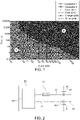
- Figure 1 is an exemplary diagram used for designing a connector system according to the state of the art. Shown is the lifetime (in units of seconds [s] on a logarithmic scale) in dependence of the current (in units of Ampère [A] likewise on a logarithmic scale) of components of the conventional connector system such as the connector itself (connector I; see the legend of the diagram) and a fuse.
- a conventional connector system using a fuse is explained below in more detail. As the behavior of the fuse strongly depends on its temperature, it is plotted in the diagram for two different temperatures -40° C and +20° C (see the legend of the diagram).
- the lines describing the behavior of the fuse can be interpreted as follows: These lines each specify (for the respective temperature, here: -40° C and +20° C), how many seconds it takes for the fuse to operate (i. e., to stop the current flow), if a certain current measured in Ampère flows through the fuse. As can be seen from the diagram of Fig. 1 , the fuse operates more slowly for lower temperatures (the curve for the fuse at -40° C runs above the curve for the fuse at +20° C). Since a worst-case scenario has to be considered for designing a safety-critical connector system, the upper curve showing the behavior of the fuse at -40° C will be considered in the following. To facilitate the following description, the diagram is divided in two disjoint areas separated by the line illustrating the fuse's behavior at -40° C: Area A is the region in the diagram below this line, and area B denotes the region in the diagram above this line.
- FIG. 1 Also shown in the diagram of Fig. 1 is the lifetime of the battery cells under the conditions of fast charging the battery system and during the conditions of an exemplary drive cycle, i. e., during use in a vehicle (see the diagram's legend for the respective lines). Both, the line illustrating the fast charging and the line illustrating the exemplary drive cycle, run below the curves indicating the behavior of the fuse, i. e., these lines run completely in area A. This is necessary, as otherwise the fuse could operate and stop the flow of current in situations of a normal use of the battery system.
- the curve showing the lifetime of a connector in the diagram can be interpreted as follows: It specifies, how many seconds it takes for the connector to become destroyed, if a certain (over-)current measured in Ampère flows through the connector.
- the curve showing the lifetime of the connector of the conventional connector system with a fuse i. e., the line of connector I; see the diagram's legend
- runs above the lines indicating the behavior of the fuse i. e., the curve of connector 1 runs completely in area B. Otherwise, i.
- area B denotes the area being protected by the fuse (at a fuse's temperature of -40° C).
- the tolerances of its components have to be taken into account. Accordingly, there must be a minimum distance (in the vertical direction) between the curve of the fuse and the curve of the connector to assure that even if the connector is destroyed earlier as assumed (for a certain over-current) or if the fuse operates later than expected (for a certain over-current), the operation of the fuse still would occur earlier than the destruction of the connector. Further, as one typically does not know the boundary conditions for the specific application, the worst case has always to be considered. Based on these conditions, the connectors, fuses and/or current measurement equipment has to be selected for designing a conventional connector system.
- the most critical effect on the lifetime of the connector system or a component thereof is caused by the temperature, which is in turn directly dependent on the current transported through the connector system.
- the main boundary conditions are no longer required for load estimation (see Figures 4 and 5 below).
- the load of the connector can be monitored.
- countermeasures can be started, e. g., by a battery management unit (BMU) or a battery management system (BMS).
- BMU battery management unit
- BMS battery management system
- a more efficient connector system can thus be used in comparison to conventional connector systems (see Figures 1 to 3 ); hence a smaller - and thus cheaper - design for a connector system can be chosen when using a connector system according to the present invention.
- FIG. 2 shows a schematic illustration of a conventional connector system with a fuse 70, wherein the connector system is integrated in a battery system.
- the battery system may be adapted as a power source of a vehicle.
- a stack of battery cells 10 is accommodated within a housing 20.
- the stack of battery cells 10 has an anode (not shown) and a cathode (not shown).
- a connector 40 having a negative connection element 41 and a positive connection element 42.
- the negative connection element 41 is connected, via a first electrical connection line 31, with the anode of the stack of battery cells 10.
- the positive connection element 42 is connected, via a second electrical connection line 32, with the cathode of the stack of battery cells 10.
- a fuse 70 Integrated into the second connection line 32 is a fuse 70.
- the fuse 70 is adapted to interrupt the electrical connection via the second connection line 32 in case the current exceeds a predefined value.
- the fuse could also be integrated into the first connection line 31 in alternative embodiments of conventional connector systems and/or battery systems.
- the connector 40 is connected with a suitable counterpart (not shown) such that the negative connection element 41 is connected with a respective counterpart connection element 51 and the positive connection element 42 is connected with a respective counterpart connection element 52.
- a load for example, a motor.
- the current at which the fuse 70 interrupts the conduction has to be adjusted to the maximum current being allowed to be transported through the connector 40 and thus, through each of the negative and positive connection elements 41, 42 of the connector 40.
- the tolerances of the fuse 70 as well as of the connector 40 have to be taken into account, i. e., for the sake of safety, the fuse 70 must be adapted to break the electrical connection at current smaller than the current, which could actually be transported by the connector 40.
- the fuse 70 During normal use, i. e., when the current conducted through the conductor 40 remains in a certain predefined range (i. e., in the range from 0 Ampère to the maximum fuse current), the fuse 70 lets the current pass through the second connection line 32. However, if the current at some point in time exceeds over a predefined threshold being defined by the maximum fuse current of the fuse 70 (i. e., in case of an overcurrent), the fuse 70 interrupts the electrical connection within the second connection line 32 such that the electric circuit with the load (not shown) and the stack of battery cells 10 is interrupted, or in other words, the stack of battery cells 10 is electrically disconnected from the load. Hence, the connector 40 is protected from overcurrent by fuse 70.
- a predefined threshold being defined by the maximum fuse current of the fuse 70
- the fuse 70 may be replaced by an amperemeter 80 connected to a control unit 90.
- the amperemeter measures the current flowing through the second connection line 32, and a signal corresponding to the current (i. e., a current signal) is sent to the control unit 90.
- the control unit 90 monitors - continuously or in sufficiently small time intervals - the strength of the current signal (which corresponds to the measured current) and checks whether or not the strength of the current signal exceeds over a predefined threshold that corresponds to the maximum current allowed to be transported through the connector 40.
- the control unit 90 triggers an electrical disconnection of the battery system from the load. This can be done, e. g., by a relay (not shown), which is implemented either within the battery system or connector system shown in Fig. 3 (i. e., in one of the first and second connection lines 31, 32) or outside of the battery system or connector system shown in Fig. 3 (e. g., in one of the counterparts 51, 52 of the connection elements 41, 42).
- a relay not shown
- the current at which the control unit 90 interrupts the electric conduction (i. e., the threshold) has to be adjusted to the maximum current being allowed to be transported through the connector 40 and thus, through each of the negative and positive connection elements 41, 42 of the connector 40.
- the threshold When adjusting the threshold to the connector 40, the tolerances of the amperemeter 80 as well as of the connector 40 have to be taken into account, i. e., for the sake of safety, the threshold must be chosen such that control unit 90 breaks the electrical connection at current smaller than the current, which could actually be transported by the connector 40.
- FIG. 4 One embodiment of the connector system according to the invention being integrated into a battery system is shown in Figure 4 .
- the basic set-up of the battery system is similar to that described above in the context of Figs. 2 and 3 .
- a stack of battery cells 10 is accommodated within a housing 20.
- the stack of battery cells 10 has an anode (not shown) and a cathode (not shown).
- Integrated in the wall of the housing 20 is a connector 40 having a negative connection element 41 and a positive connection element 42.
- the negative connection element 41 is connected, via a first electrical connection line 31, with the anode of the stack of battery cells 10.
- the positive connection element 42 is connected, via a second electrical connection line 32, with the cathode of the stack of battery cells 10.
- a first temperature sensor 61 is thermally connected to the negative connection element 41 and a second temperature sensor 62 is connected to the positive connection element 42.
- Each of the first and second temperature sensors 61, 62 may be a thermistor, for example a negative temperature coefficient thermistor (NTC thermistor) or a positive coefficient temperature thermistor (PTC thermistor), or a thermocouple.
- NTC thermistor negative temperature coefficient thermistor
- PTC thermistor positive coefficient temperature thermistor
- thermocouple thermocouple
- the first and second temperature sensors 61, 62 are of the same type.
- the first temperature sensor 61 measures the temperature of the negative connection element 41 and generates a corresponding first temperature signal encoding the measured temperature of the negative connection element 41.
- the first temperature signal is then transmitted to a control unit 90.
- the second temperature sensor 62 measures the temperature of the positive connection element 42 and generates a corresponding second temperature signal encoding the measured temperature of the positive connection element 42.
- the second temperature signal is then also transmitted to the control unit 90.
- Each of the first and second temperature signal may be an electric signal (e. g., a voltage level) depending monotonously on the measured temperature.
- the temperature signal may also be a wireless signal, e. g., a near-field communication (NFC) signal or a WLAN signal or the like.
- NFC near-field communication
- the control unit 90 compares temperature signals received from the first and second temperature sensor 61, 62.
- the comparison can be performed using analog (non-digital) methods or using digital methods.
- the control unit generates a first value based on the first temperature signal and a second value based on the second temperature signal.
- the first value may directly be the strength of the first temperature signal and the second value may directly be the strength of the second temperature signal.
- the types of the sensors are not identical, at least one of the first and second temperature signals may be transformed such that first value and second value yield temperature values in the same temperature scale.
- the first and second values may correspond to the temperature in a standardized temperature scale (e. g., correspond to units in °C). However, the first and second values may correspond to any other temperature scale, which may be linear or non-linear. It is preferred that first and second value encode or correspond to the measured temperature in the same scale.
- the measured temperatures in a certain temperature scale
- the measured temperature in the same scale
- a mean value e. g., the arithmetic mean
- the comparison may be performed by calculating the difference between the first value (based on the first temperature signal) and the second value (based on the second temperature signal). Then, if the absolute value of the difference exceeds a predefined value, the control unit 90 generates an alert signal.
- the alert signal may be provided at an output of the control unit.
- the alert signal may be an electric signal (e. g., a voltage level) and/or a wireless signal, e. g., a near-field communication (NFC) signal or a WLAN signal or the like.
- connection elements 41, 42 and its respective counterpart connection element 51, 52 (the latter not being part of the invention) is increased, which in turn may indicate a connection failure.
- the absolute temperatures measured at the negative and/or positive connection element 41, 42 may be supervised by the control unit 90. Then the control unit 90 may also output an alert signal indicating that the maximum allowed temperature of one of the connection elements 41, 42 has been exceeded.
- the alert signal may be configured such that it directly suitable to control a relay 98 as shown in Figure 5 .
- the relay 98 is implemented into the second connection line 32 between the positive connection element 42 and the cathode of the stack of battery cells 10.
- the relay 98 could alternatively also be implemented into the first connection line 31.
- the control unit 90 is connected, via a signal line 96, to the relay 98 and operates the relay 98 such that the relay 98 interrupts the second connection line 32 upon receiving a respective signal (a current) from the control unit 90.
- the relay 98 could also be positioned outside the battery system (e.
- the alert signal can also be transmitted to the load itself or a further control unit controlling the load (not shown) such that the load is shut down in response to receiving the alert signal.
- the alert signal could also be transmitted from the control unit 90 to a battery management unit (BMU; not shown in the figures) of the battery system. Then, the BMU may control the operations upon receiving the alert signal from the control unit 90.
- the BMU may be configured to control a relay so as to interrupt the circuit powered by the battery system or may be configured to shut down the load driven by the battery system.
- the control unit 90 may be integrated within the BMU.
Landscapes
- Engineering & Computer Science (AREA)
- Chemical & Material Sciences (AREA)
- Chemical Kinetics & Catalysis (AREA)
- Electrochemistry (AREA)
- General Chemical & Material Sciences (AREA)
- Power Engineering (AREA)
- Mechanical Engineering (AREA)
- Transportation (AREA)
- Manufacturing & Machinery (AREA)
- Sustainable Energy (AREA)
- Sustainable Development (AREA)
- Life Sciences & Earth Sciences (AREA)
- Physics & Mathematics (AREA)
- General Physics & Mathematics (AREA)
- Business, Economics & Management (AREA)
- Emergency Management (AREA)
- Aviation & Aerospace Engineering (AREA)
- Microelectronics & Electronic Packaging (AREA)
- Charge And Discharge Circuits For Batteries Or The Like (AREA)
Priority Applications (4)
| Application Number | Priority Date | Filing Date | Title |
|---|---|---|---|
| EP21158086.5A EP4047713A1 (fr) | 2021-02-19 | 2021-02-19 | Protection thermique de connecteur |
| KR1020220013665A KR102721211B1 (ko) | 2021-02-19 | 2022-01-28 | 배터리 시스템과의 전기적 연결을 설정하기 위한 커넥터 시스템 및 방법 |
| CN202210124125.XA CN114976495B (zh) | 2021-02-19 | 2022-02-10 | 连接器的热保护 |
| US17/673,626 US11900785B2 (en) | 2021-02-19 | 2022-02-16 | Thermal protection of connector |
Applications Claiming Priority (1)
| Application Number | Priority Date | Filing Date | Title |
|---|---|---|---|
| EP21158086.5A EP4047713A1 (fr) | 2021-02-19 | 2021-02-19 | Protection thermique de connecteur |
Publications (1)
| Publication Number | Publication Date |
|---|---|
| EP4047713A1 true EP4047713A1 (fr) | 2022-08-24 |
Family
ID=74672122
Family Applications (1)
| Application Number | Title | Priority Date | Filing Date |
|---|---|---|---|
| EP21158086.5A Pending EP4047713A1 (fr) | 2021-02-19 | 2021-02-19 | Protection thermique de connecteur |
Country Status (2)
| Country | Link |
|---|---|
| EP (1) | EP4047713A1 (fr) |
| KR (1) | KR102721211B1 (fr) |
Cited By (3)
| Publication number | Priority date | Publication date | Assignee | Title |
|---|---|---|---|---|
| WO2024194547A1 (fr) * | 2023-03-22 | 2024-09-26 | Stellantis Auto Sas | Procede de detection d'un desserrage d'une liaison electrique vissee dans une batterie electrique |
| FR3147002A1 (fr) * | 2023-03-22 | 2024-09-27 | Psa Automobiles Sa | Procede de detection d’un desserrage d’une liaison electrique vissee dans une batterie electrique |
| WO2026015069A1 (fr) * | 2024-07-12 | 2026-01-15 | Zparq Ab | Carte de circuit imprimé d'un bloc-batterie pour interconnecter des éléments de batterie, bloc-batterie et procédé associé |
Citations (4)
| Publication number | Priority date | Publication date | Assignee | Title |
|---|---|---|---|---|
| US20110298472A1 (en) * | 2010-06-07 | 2011-12-08 | Steve Carkner | Battery connection failure detection system |
| US20140268473A1 (en) * | 2013-03-14 | 2014-09-18 | Tyco Electronics Corporation | Electric vehicle support equipment having a smart plug with a relay control circuit |
| US20190319317A1 (en) * | 2017-01-23 | 2019-10-17 | Panasonic Intellectual Property Management Co., Ltd. | Contact failure detection system |
| EP3683087A1 (fr) * | 2019-01-17 | 2020-07-22 | Samsung SDI Co., Ltd. | Relais comportant des capteurs de température pour des applications de sécurité selon iso 26262 |
-
2021
- 2021-02-19 EP EP21158086.5A patent/EP4047713A1/fr active Pending
-
2022
- 2022-01-28 KR KR1020220013665A patent/KR102721211B1/ko active Active
Patent Citations (4)
| Publication number | Priority date | Publication date | Assignee | Title |
|---|---|---|---|---|
| US20110298472A1 (en) * | 2010-06-07 | 2011-12-08 | Steve Carkner | Battery connection failure detection system |
| US20140268473A1 (en) * | 2013-03-14 | 2014-09-18 | Tyco Electronics Corporation | Electric vehicle support equipment having a smart plug with a relay control circuit |
| US20190319317A1 (en) * | 2017-01-23 | 2019-10-17 | Panasonic Intellectual Property Management Co., Ltd. | Contact failure detection system |
| EP3683087A1 (fr) * | 2019-01-17 | 2020-07-22 | Samsung SDI Co., Ltd. | Relais comportant des capteurs de température pour des applications de sécurité selon iso 26262 |
Cited By (4)
| Publication number | Priority date | Publication date | Assignee | Title |
|---|---|---|---|---|
| WO2024194547A1 (fr) * | 2023-03-22 | 2024-09-26 | Stellantis Auto Sas | Procede de detection d'un desserrage d'une liaison electrique vissee dans une batterie electrique |
| FR3147001A1 (fr) * | 2023-03-22 | 2024-09-27 | Psa Automobiles Sa | Procede de detection d’un desserrage d’une liaison electrique vissee dans une batterie electrique |
| FR3147002A1 (fr) * | 2023-03-22 | 2024-09-27 | Psa Automobiles Sa | Procede de detection d’un desserrage d’une liaison electrique vissee dans une batterie electrique |
| WO2026015069A1 (fr) * | 2024-07-12 | 2026-01-15 | Zparq Ab | Carte de circuit imprimé d'un bloc-batterie pour interconnecter des éléments de batterie, bloc-batterie et procédé associé |
Also Published As
| Publication number | Publication date |
|---|---|
| KR20220119314A (ko) | 2022-08-29 |
| KR102721211B1 (ko) | 2024-10-23 |
Similar Documents
| Publication | Publication Date | Title |
|---|---|---|
| EP3965207B1 (fr) | Système de batterie avec unité de déconnexion de batterie avancée | |
| US11801753B2 (en) | Battery system and vehicle including the battery system | |
| EP3633754B1 (fr) | Système de batterie pour un véhicule et procédé de détection d'une situation de surchauffe du système de batterie | |
| EP4047713A1 (fr) | Protection thermique de connecteur | |
| CN113904005B (zh) | 用于在低温下最大化充电功率的阳极电位的在线测量 | |
| US11900785B2 (en) | Thermal protection of connector | |
| EP3680955B1 (fr) | Système de batterie | |
| US12609423B2 (en) | Relay control system and battery system | |
| US12487132B2 (en) | Temperature-dependent resistor network for temperature anomaly monitoring in a battery system | |
| EP4089790B1 (fr) | Cellule de batterie et système de batterie comprenant une cellule de batterie | |
| EP4060785B1 (fr) | Système de batterie et véhicule comprenant le système de batterie | |
| KR20230034174A (ko) | 전지 시스템, 이의 비정상 작동 상태 감지 방법 및 전기 차량 | |
| KR102843391B1 (ko) | 릴레이, 릴레이 시스템 및 릴레이 시스템의 동작 방법 | |
| EP3965198A1 (fr) | Mesure en ligne de potentiel d'anode pour maximiser la puissance de chargement à basses températures | |
| US11444337B2 (en) | Solid state switch driver circuit for a battery system | |
| CN115764008A (zh) | 电池系统、检测其异常工作状况的方法以及电动车辆 | |
| EP3916880B1 (fr) | Réseau de résistances dépendant de la température pour la surveillance d'anomalies de température dans un système de batterie | |
| US12580233B2 (en) | Battery system and method for operating the same | |
| US20250174773A1 (en) | Temperature-sensitive housing for a battery cell | |
| EP3657592B1 (fr) | Unité de commande pour un module ou un système de batterie | |
| EP3708403B1 (fr) | Circuit de commande de commutateur à semiconducteurs pour un système de batterie | |
| EP4124498A1 (fr) | Système de commande de relais et système de batterie | |
| EP4513615A1 (fr) | Système de batterie et procédé d'assemblage d'un système de batterie | |
| EP4186746A1 (fr) | Système de batterie et son procédé de fonctionnement |
Legal Events
| Date | Code | Title | Description |
|---|---|---|---|
| PUAI | Public reference made under article 153(3) epc to a published international application that has entered the european phase |
Free format text: ORIGINAL CODE: 0009012 |
|
| STAA | Information on the status of an ep patent application or granted ep patent |
Free format text: STATUS: REQUEST FOR EXAMINATION WAS MADE |
|
| 17P | Request for examination filed |
Effective date: 20211210 |
|
| AK | Designated contracting states |
Kind code of ref document: A1 Designated state(s): AL AT BE BG CH CY CZ DE DK EE ES FI FR GB GR HR HU IE IS IT LI LT LU LV MC MK MT NL NO PL PT RO RS SE SI SK SM TR |
|
| STAA | Information on the status of an ep patent application or granted ep patent |
Free format text: STATUS: EXAMINATION IS IN PROGRESS |
|
| 17Q | First examination report despatched |
Effective date: 20240125 |