EP4047731A2 - Ensemble cellule de batterie et bloc-batterie le comprenant - Google Patents
Ensemble cellule de batterie et bloc-batterie le comprenant Download PDFInfo
- Publication number
- EP4047731A2 EP4047731A2 EP22157694.5A EP22157694A EP4047731A2 EP 4047731 A2 EP4047731 A2 EP 4047731A2 EP 22157694 A EP22157694 A EP 22157694A EP 4047731 A2 EP4047731 A2 EP 4047731A2
- Authority
- EP
- European Patent Office
- Prior art keywords
- bus
- battery cell
- barrier
- assembly
- battery
- Prior art date
- Legal status (The legal status is an assumption and is not a legal conclusion. Google has not performed a legal analysis and makes no representation as to the accuracy of the status listed.)
- Pending
Links
Images





Classifications
-
- H—ELECTRICITY
- H01—ELECTRIC ELEMENTS
- H01M—PROCESSES OR MEANS, e.g. BATTERIES, FOR THE DIRECT CONVERSION OF CHEMICAL ENERGY INTO ELECTRICAL ENERGY
- H01M50/00—Constructional details or processes of manufacture of the non-active parts of electrochemical cells other than fuel cells, e.g. hybrid cells
- H01M50/50—Current conducting connections for cells or batteries
- H01M50/502—Interconnectors for connecting terminals of adjacent batteries; Interconnectors for connecting cells outside a battery casing
- H01M50/503—Interconnectors for connecting terminals of adjacent batteries; Interconnectors for connecting cells outside a battery casing characterised by the shape of the interconnectors
-
- H—ELECTRICITY
- H01—ELECTRIC ELEMENTS
- H01M—PROCESSES OR MEANS, e.g. BATTERIES, FOR THE DIRECT CONVERSION OF CHEMICAL ENERGY INTO ELECTRICAL ENERGY
- H01M50/00—Constructional details or processes of manufacture of the non-active parts of electrochemical cells other than fuel cells, e.g. hybrid cells
- H01M50/20—Mountings; Secondary casings or frames; Racks, modules or packs; Suspension devices; Shock absorbers; Transport or carrying devices; Holders
- H01M50/204—Racks, modules or packs for multiple batteries or multiple cells
-
- H—ELECTRICITY
- H01—ELECTRIC ELEMENTS
- H01M—PROCESSES OR MEANS, e.g. BATTERIES, FOR THE DIRECT CONVERSION OF CHEMICAL ENERGY INTO ELECTRICAL ENERGY
- H01M50/00—Constructional details or processes of manufacture of the non-active parts of electrochemical cells other than fuel cells, e.g. hybrid cells
- H01M50/20—Mountings; Secondary casings or frames; Racks, modules or packs; Suspension devices; Shock absorbers; Transport or carrying devices; Holders
- H01M50/204—Racks, modules or packs for multiple batteries or multiple cells
- H01M50/207—Racks, modules or packs for multiple batteries or multiple cells characterised by their shape
- H01M50/211—Racks, modules or packs for multiple batteries or multiple cells characterised by their shape adapted for pouch cells
-
- H—ELECTRICITY
- H01—ELECTRIC ELEMENTS
- H01M—PROCESSES OR MEANS, e.g. BATTERIES, FOR THE DIRECT CONVERSION OF CHEMICAL ENERGY INTO ELECTRICAL ENERGY
- H01M50/00—Constructional details or processes of manufacture of the non-active parts of electrochemical cells other than fuel cells, e.g. hybrid cells
- H01M50/20—Mountings; Secondary casings or frames; Racks, modules or packs; Suspension devices; Shock absorbers; Transport or carrying devices; Holders
- H01M50/233—Mountings; Secondary casings or frames; Racks, modules or packs; Suspension devices; Shock absorbers; Transport or carrying devices; Holders characterised by physical properties of casings or racks, e.g. dimensions
- H01M50/24—Mountings; Secondary casings or frames; Racks, modules or packs; Suspension devices; Shock absorbers; Transport or carrying devices; Holders characterised by physical properties of casings or racks, e.g. dimensions adapted for protecting batteries from their environment, e.g. from corrosion
-
- H—ELECTRICITY
- H01—ELECTRIC ELEMENTS
- H01M—PROCESSES OR MEANS, e.g. BATTERIES, FOR THE DIRECT CONVERSION OF CHEMICAL ENERGY INTO ELECTRICAL ENERGY
- H01M50/00—Constructional details or processes of manufacture of the non-active parts of electrochemical cells other than fuel cells, e.g. hybrid cells
- H01M50/20—Mountings; Secondary casings or frames; Racks, modules or packs; Suspension devices; Shock absorbers; Transport or carrying devices; Holders
- H01M50/249—Mountings; Secondary casings or frames; Racks, modules or packs; Suspension devices; Shock absorbers; Transport or carrying devices; Holders specially adapted for aircraft or vehicles, e.g. cars or trains
-
- H—ELECTRICITY
- H01—ELECTRIC ELEMENTS
- H01M—PROCESSES OR MEANS, e.g. BATTERIES, FOR THE DIRECT CONVERSION OF CHEMICAL ENERGY INTO ELECTRICAL ENERGY
- H01M50/00—Constructional details or processes of manufacture of the non-active parts of electrochemical cells other than fuel cells, e.g. hybrid cells
- H01M50/20—Mountings; Secondary casings or frames; Racks, modules or packs; Suspension devices; Shock absorbers; Transport or carrying devices; Holders
- H01M50/262—Mountings; Secondary casings or frames; Racks, modules or packs; Suspension devices; Shock absorbers; Transport or carrying devices; Holders with fastening means, e.g. locks
-
- H—ELECTRICITY
- H01—ELECTRIC ELEMENTS
- H01M—PROCESSES OR MEANS, e.g. BATTERIES, FOR THE DIRECT CONVERSION OF CHEMICAL ENERGY INTO ELECTRICAL ENERGY
- H01M50/00—Constructional details or processes of manufacture of the non-active parts of electrochemical cells other than fuel cells, e.g. hybrid cells
- H01M50/20—Mountings; Secondary casings or frames; Racks, modules or packs; Suspension devices; Shock absorbers; Transport or carrying devices; Holders
- H01M50/289—Mountings; Secondary casings or frames; Racks, modules or packs; Suspension devices; Shock absorbers; Transport or carrying devices; Holders characterised by spacing elements or positioning means within frames, racks or packs
-
- H—ELECTRICITY
- H01—ELECTRIC ELEMENTS
- H01M—PROCESSES OR MEANS, e.g. BATTERIES, FOR THE DIRECT CONVERSION OF CHEMICAL ENERGY INTO ELECTRICAL ENERGY
- H01M50/00—Constructional details or processes of manufacture of the non-active parts of electrochemical cells other than fuel cells, e.g. hybrid cells
- H01M50/20—Mountings; Secondary casings or frames; Racks, modules or packs; Suspension devices; Shock absorbers; Transport or carrying devices; Holders
- H01M50/289—Mountings; Secondary casings or frames; Racks, modules or packs; Suspension devices; Shock absorbers; Transport or carrying devices; Holders characterised by spacing elements or positioning means within frames, racks or packs
- H01M50/291—Mountings; Secondary casings or frames; Racks, modules or packs; Suspension devices; Shock absorbers; Transport or carrying devices; Holders characterised by spacing elements or positioning means within frames, racks or packs characterised by their shape
-
- H—ELECTRICITY
- H01—ELECTRIC ELEMENTS
- H01M—PROCESSES OR MEANS, e.g. BATTERIES, FOR THE DIRECT CONVERSION OF CHEMICAL ENERGY INTO ELECTRICAL ENERGY
- H01M50/00—Constructional details or processes of manufacture of the non-active parts of electrochemical cells other than fuel cells, e.g. hybrid cells
- H01M50/20—Mountings; Secondary casings or frames; Racks, modules or packs; Suspension devices; Shock absorbers; Transport or carrying devices; Holders
- H01M50/289—Mountings; Secondary casings or frames; Racks, modules or packs; Suspension devices; Shock absorbers; Transport or carrying devices; Holders characterised by spacing elements or positioning means within frames, racks or packs
- H01M50/293—Mountings; Secondary casings or frames; Racks, modules or packs; Suspension devices; Shock absorbers; Transport or carrying devices; Holders characterised by spacing elements or positioning means within frames, racks or packs characterised by the material
-
- H—ELECTRICITY
- H01—ELECTRIC ELEMENTS
- H01M—PROCESSES OR MEANS, e.g. BATTERIES, FOR THE DIRECT CONVERSION OF CHEMICAL ENERGY INTO ELECTRICAL ENERGY
- H01M50/00—Constructional details or processes of manufacture of the non-active parts of electrochemical cells other than fuel cells, e.g. hybrid cells
- H01M50/30—Arrangements for facilitating escape of gases
- H01M50/383—Flame arresting or ignition-preventing means
-
- H—ELECTRICITY
- H01—ELECTRIC ELEMENTS
- H01M—PROCESSES OR MEANS, e.g. BATTERIES, FOR THE DIRECT CONVERSION OF CHEMICAL ENERGY INTO ELECTRICAL ENERGY
- H01M50/00—Constructional details or processes of manufacture of the non-active parts of electrochemical cells other than fuel cells, e.g. hybrid cells
- H01M50/50—Current conducting connections for cells or batteries
- H01M50/502—Interconnectors for connecting terminals of adjacent batteries; Interconnectors for connecting cells outside a battery casing
-
- H—ELECTRICITY
- H01—ELECTRIC ELEMENTS
- H01M—PROCESSES OR MEANS, e.g. BATTERIES, FOR THE DIRECT CONVERSION OF CHEMICAL ENERGY INTO ELECTRICAL ENERGY
- H01M50/00—Constructional details or processes of manufacture of the non-active parts of electrochemical cells other than fuel cells, e.g. hybrid cells
- H01M50/50—Current conducting connections for cells or batteries
- H01M50/502—Interconnectors for connecting terminals of adjacent batteries; Interconnectors for connecting cells outside a battery casing
- H01M50/507—Interconnectors for connecting terminals of adjacent batteries; Interconnectors for connecting cells outside a battery casing comprising an arrangement of two or more busbars within a container structure, e.g. busbar modules
-
- H—ELECTRICITY
- H01—ELECTRIC ELEMENTS
- H01M—PROCESSES OR MEANS, e.g. BATTERIES, FOR THE DIRECT CONVERSION OF CHEMICAL ENERGY INTO ELECTRICAL ENERGY
- H01M50/00—Constructional details or processes of manufacture of the non-active parts of electrochemical cells other than fuel cells, e.g. hybrid cells
- H01M50/50—Current conducting connections for cells or batteries
- H01M50/502—Interconnectors for connecting terminals of adjacent batteries; Interconnectors for connecting cells outside a battery casing
- H01M50/514—Methods for interconnecting adjacent batteries or cells
- H01M50/516—Methods for interconnecting adjacent batteries or cells by welding, soldering or brazing
-
- H—ELECTRICITY
- H01—ELECTRIC ELEMENTS
- H01M—PROCESSES OR MEANS, e.g. BATTERIES, FOR THE DIRECT CONVERSION OF CHEMICAL ENERGY INTO ELECTRICAL ENERGY
- H01M50/00—Constructional details or processes of manufacture of the non-active parts of electrochemical cells other than fuel cells, e.g. hybrid cells
- H01M50/50—Current conducting connections for cells or batteries
- H01M50/531—Electrode connections inside a battery casing
- H01M50/533—Electrode connections inside a battery casing characterised by the shape of the leads or tabs
-
- H—ELECTRICITY
- H01—ELECTRIC ELEMENTS
- H01M—PROCESSES OR MEANS, e.g. BATTERIES, FOR THE DIRECT CONVERSION OF CHEMICAL ENERGY INTO ELECTRICAL ENERGY
- H01M50/00—Constructional details or processes of manufacture of the non-active parts of electrochemical cells other than fuel cells, e.g. hybrid cells
- H01M50/50—Current conducting connections for cells or batteries
- H01M50/572—Means for preventing undesired use or discharge
- H01M50/584—Means for preventing undesired use or discharge for preventing incorrect connections inside or outside the batteries
- H01M50/588—Means for preventing undesired use or discharge for preventing incorrect connections inside or outside the batteries outside the batteries, e.g. incorrect connections of terminals or busbars
-
- H—ELECTRICITY
- H01—ELECTRIC ELEMENTS
- H01M—PROCESSES OR MEANS, e.g. BATTERIES, FOR THE DIRECT CONVERSION OF CHEMICAL ENERGY INTO ELECTRICAL ENERGY
- H01M50/00—Constructional details or processes of manufacture of the non-active parts of electrochemical cells other than fuel cells, e.g. hybrid cells
- H01M50/50—Current conducting connections for cells or batteries
- H01M50/572—Means for preventing undesired use or discharge
- H01M50/584—Means for preventing undesired use or discharge for preventing incorrect connections inside or outside the batteries
- H01M50/59—Means for preventing undesired use or discharge for preventing incorrect connections inside or outside the batteries characterised by the protection means
-
- H—ELECTRICITY
- H01—ELECTRIC ELEMENTS
- H01M—PROCESSES OR MEANS, e.g. BATTERIES, FOR THE DIRECT CONVERSION OF CHEMICAL ENERGY INTO ELECTRICAL ENERGY
- H01M2200/00—Safety devices for primary or secondary batteries
-
- H—ELECTRICITY
- H01—ELECTRIC ELEMENTS
- H01M—PROCESSES OR MEANS, e.g. BATTERIES, FOR THE DIRECT CONVERSION OF CHEMICAL ENERGY INTO ELECTRICAL ENERGY
- H01M2220/00—Batteries for particular applications
- H01M2220/20—Batteries in motive systems, e.g. vehicle, ship, plane
-
- Y—GENERAL TAGGING OF NEW TECHNOLOGICAL DEVELOPMENTS; GENERAL TAGGING OF CROSS-SECTIONAL TECHNOLOGIES SPANNING OVER SEVERAL SECTIONS OF THE IPC; TECHNICAL SUBJECTS COVERED BY FORMER USPC CROSS-REFERENCE ART COLLECTIONS [XRACs] AND DIGESTS
- Y02—TECHNOLOGIES OR APPLICATIONS FOR MITIGATION OR ADAPTATION AGAINST CLIMATE CHANGE
- Y02E—REDUCTION OF GREENHOUSE GAS [GHG] EMISSIONS, RELATED TO ENERGY GENERATION, TRANSMISSION OR DISTRIBUTION
- Y02E60/00—Enabling technologies; Technologies with a potential or indirect contribution to GHG emissions mitigation
- Y02E60/10—Energy storage using batteries
Definitions
- Example embodiments of the present disclosure relate to a battery cell assembly and a battery pack including the same.
- a battery cell may be repeatedly charged and discharged as conversion between chemical energy and electrical energy is reversible.
- battery cells may generate heat while being charged and discharged, such that a battery cell among the battery cells may explode due to an increase of temperature of the battery cells, or may explode due to external impacts, which may be problematic.
- the explosion of one of the battery cells may cause high temperature and high pressure in the other battery cells, such that the battery cells may explode consecutively.
- An example embodiment of the present disclosure is to provide a battery cell assembly which may address the issue of consecutive explosion of battery cells caused by flames, gas, or the like, generated by an explosion of one of the battery cells, and a battery pack including the same.
- An example embodiment of the present disclosure is to provide a battery cell assembly which may allow a barrier to be easily installed, and a battery pack including the same.
- An example embodiment of the present disclosure is to, by increasing capacity of a battery cell, increase total capacity of a battery pack including a plurality of battery cell assemblies.
- a battery cell assembly includes a plurality of battery cells, a bus-bar assembly to which electrode leads of the plurality of battery cells are coupled, and a barrier interposed between the plurality of battery cells and coupled to the bus-bar assembly.
- the bus-bar assembly may include a bus-bar frame having a lead hole into which the electrode lead is inserted, and a support tab protruding from the bus-bar frame toward the battery cells, wherein an end of the barrier is inserted into the support tab.
- the support tab may include a pair of side tabs protruding to oppose both side surfaces of the end of the barrier, respectively, and a blocking tab opposing at least one of an upper portion and a lower portion of the end of the barrier and configured to connect the pair of side tabs to each other.
- the pair of side tabs may be spaced apart from each other and form a gap, and a width of the gap of a lower end may be greater than a width of the gap of an upper end.
- the pair of side tabs may be formed such that a lower end thereof may protrude further than an upper end from the bus-bar frame in a direction of the at least one of the battery cells.
- the support tab may include a pair of side tabs protruding to oppose both side surfaces of the end of the barrier
- the barrier may include a barrier plate opposing a side surface of the battery cell, and a snap portion protruding from ends of the barrier plate to both sides configured to be caught on a hook formed on internal surfaces of the pair of side tabs.
- the snap portion is formed that a front surface opposing the bus-bar assembly may be tapered.
- the barrier may include a barrier plate opposing a side surface of the at least one of the battery cells, a seating block configured to protrude from a lower side surface of the end of the barrier plate in a direction of the bus-bar frame such that a lower end of the support tab is seated, and a confinement post spaced apart from the barrier plate, configured to protrude upwardly from the seating block, and inserted into an accommodation groove formed upwardly from the lower end of the support tab.
- the barrier may include a barrier plate opposing a side surface of the at least one of the battery cells, and a fastening block provided on a lower portion of the end of the barrier plate, configured to have a thickness greater than that of the barrier plate, and fastened to the bus-bar assembly by bolts.
- the barrier may be formed of a material including at least one of a mica material, a metal material, and a resin material.
- the barrier may include a buffer pad on an external surface.
- the electrode lead may be welded and coupled to the bus-bar of the bus-bar assembly while an end thereof is disposed in a lead hole formed in the bus-bar assembly.
- the electrode lead may penetrate through a lead hole formed in the bus-bar assembly and may be bent to be welded and coupled to the bus-bar of the bus-bar assembly, and a first electrode lead disposed on one end of the bus-bar may be bent in a direction opposite to a second electrode lead, the other electrode lead.
- a battery pack includes a plurality of battery cell assemblies, and a pack housing accommodating the plurality of battery cell assemblies, wherein the plurality of battery cell assemblies include a plurality of battery cells including electrode leads, a bus-bar assembly coupled to the electrode lead, and a barrier interposed between the plurality of battery cells and coupled to the bus-bar assembly.
- the plurality of battery cells may be seated on a thermal conductive material disposed on the pack housing.
- FIG. 1 is an exploded perspective diagram illustrating a battery cell assembly 1 according to an example embodiment.
- FIG. 2 is a perspective diagram illustrating a portion of a battery cell assembly 1 in which a barrier 30 is fastened to a bus-bar assembly 20 according to an example embodiment.
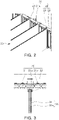
- FIG. 3 is a plan diagram illustrating a state in which a barrier 30 is partially inserted into a support tab 22 in a battery cell assembly 1 according to an example embodiment.
- FIG. 4 is a plan diagram illustrating a state in which flames and gas g generated by battery cells 10 in a battery cell assembly 1 are not spread by a barrier 30 and are discharged through a vent hole 21c according to an example embodiment.
- the battery cell assembly 1 in an example embodiment may include a plurality of battery cells 10, a bus-bar assembly 20, and a barrier 30.
- the bus-bar assembly 20 may be coupled to electrode leads 11 of the plurality of battery cells 10.
- the barrier 30 may be interposed between the plurality of battery cells 10, and an end thereof may be fastened to the bus-bar assembly 20. Accordingly, for example, the space in which the battery cells 10 on both sides of the barrier 30 are disposed may be separated.
- the barrier 30 covers the side surface of the battery cell 10 and the battery cell 10 is disposed in the separated space formed by fastening(or coupling) the end of the barrier 30 to the bus-bar assembly 20, the issue in which the consecutive explosion of the battery cells 10 caused by flames and the gas g generated by one of the battery cells 10 may be addressed.
- the effect of preventing flames and the gas g from spreading may improve.
- the battery cell assembly 1 in the example embodiment may be configured in the form of a battery module, may be manufactured as a battery pack, and may be installed in an electrical vehicle or the like, or the process of manufacturing the battery cell assembly 1 as a battery module may not be performed and the battery cell assembly 1 may be installed in an in the electrical vehicle form of a battery pack (cell to pack; CTP), such that electrical capacity of the battery pack may increase.
- a battery pack cell to pack; CTP
- the battery cell 10 may include an electrode assembly and a cell body member surrounding the electrode assembly.
- the electrode assembly may substantially include electrolyte and may be accommodated in the cell body member together.
- the electrolyte may include an organic solvent such as ethylene carbonate (EC), propylene carbonate (PC), diethyl carbonate (DEC), ethyl methyl carbonate (EMC), or dimethyl carbonate (DMC) and a lithium salt such as LiPF 6 or LiBF 4 . Further, the electrolyte may be in the form of a liquid, solid or gel.
- the cell body member may be configured to protect the electrode assembly and to accommodate the electrolyte, and for example, the cell body member may be provided as a pouch-type member or a can-type member.
- the pouch-type member may be configured to seal and accommodate the electrode assembly on three sides, and the three surfaces, which are an upper surface portion and both side surface portions, other than one surface portion which is one surface portion, may be folded and bonded to seal the electrode assembly while the electrode assembly is accommodated therein.
- the can-type member may seal and accommodate the electrode assembly on one surface, and a single surface, which is an upper surface portion, other than four surfaces which are a lower surface portion and side surface portions, may be bonded to seal the electrode assembly while the electrode assembly is accommodated.
- the pouch-type battery cell 10 and the can-type battery cell 10 are merely examples of the battery cells 10 included in the battery cell assembly 1 in the example embodiment, and the type of the battery cell 10 included in the battery cell assembly 1 is not limited to the aforementioned example.
- the bus-bar assembly 20 may be coupled to the plurality of battery cells 10, and may entirely support the plurality of battery cells 10, and may allow the plurality of battery cells 10 to be electrically connected to an external entity.
- the bus-bar assembly 20 may include a bus-bar frame 21.
- a plurality of lead holes 21a to which the electrode leads 11 of the battery cells 10 are coupled may be formed in the bus-bar frame 21. Accordingly, the entirety of the plurality of battery cells 10 may be coupled to the bus-bar assembly 20 via the electrode lead 11.
- an end of the electrode lead 11 may be welded to the bus-bar 21b disposed in the lead hole 21a formed in the bus-bar assembly 20.
- the space occupied by the battery cell assembly 1 may be reduced.
- the electrode lead 11 may be configured to penetrate through the lead hole 21a and to be bent, and a detailed description thereof will be described later with reference to FIG. 10A and 10B .
- the bus-bar assembly 20 may include a support tab 22.
- the end of the barrier 30 may be fastened to the bus-bar assembly 20 by the support tab 22.
- the barrier 30 may be easily installed.
- the bus-bar assembly 20 of the battery cell assembly 1 in an example embodiment may include a bus-bar frame 21 having a lead hole 21a into which the electrode lead 11 is inserted, and a support tab 22 protruding toward the battery cell 10 and an end of the barrier 30 is inserted into the support tab 22.
- the support tab 22 may include a side tab 23 for guiding the movement of the barrier 30 when the barrier 30 is fastened. Also, the support tab 22 may further include a blocking tab 24 limiting a fastening position of the barrier 30.
- a pair of the side tab 23 may be provided and may protrude to oppose both side surfaces of the end of the barrier 30, respectively.
- the blocking tab 24 may oppose at least one of an upper portion and a lower portion of the end of the barrier 30, and may connect the pair of side tabs 23 to each other.
- the pair of side tabs 23 may be formed such that a gap width W therebetween may gradually increase from the upper end to the lower end, and a detailed description thereof will be described later with reference to FIG. 5 .
- the side tab 23 may more specifically specify a protruding shape thereof, protruding from the bus-bar frame 21, and a detailed description thereof will be described later with reference to FIG. 6A and 6B .
- the bus-bar assembly 20 of the battery cell assembly 1 in an example embodiment may include a bus-bar frame 21 and a support tab 22, and a hook 23a may be formed on the side tab 23 23a and may be fastened to the snap portion 32 of the barrier 30. A detailed description thereof will be described later with reference to FIG. 9 .
- the bus-bar assembly 20 may have a vent hole 21c for discharging flames and the gas g, generated in the battery cell 10 to the outside. Accordingly, flames and the gas g, generated in one of the battery cells 10 may not pass over the barrier 30 may not spread to the other battery cells 10, and may be discharged to the outside through the vent hole 21c.
- the barrier 30 may be configured to prevent flames and the gas g generated by the explosion of one battery cell 10 from spreading to the adjacent battery cells 10.
- the barrier 30 may cover the side surface of the battery cell 10, and an end of the barrier 30 may be fastened to the bus-bar assembly 20. Accordingly, the battery cells 10 on both sides may be spatially separated from each other with respect to the barrier 30 as the center, and accordingly, the explosion of the battery cells 10 in one region may be prevented from affecting the battery cells 10 in the other region.
- the barrier 30 may be disposed for each battery cell 10 of a certain number of units among the plurality of battery cells 10.
- the barrier 30 may be provided between adjacent battery cells 10, thereby covering the side surface of the battery cell 10.
- the barrier 30 may be installed for every four battery cells 10 and may spatially separate the four battery cells 10 from each other. Accordingly, when one of the four battery cells 10 explodes, only the four battery cells 10 may consecutively explode to the maximum, and further explosion may be prevented by the barrier 30 and the bus-bar assembly 20.
- the barrier 30 may include the barrier plate 31 and the fastening block 35, and accordingly, the barrier 30 may be fastened to the bus-bar assembly 20 by the bolts 35a. A detailed description thereof will be described later with reference to FIG. 8 .
- the barrier 30 of the battery cell assembly 1 in an example embodiment may be formed of a material including at least one of a mica material, a metal material, and a resin material.
- a mica material, a metal material, and a resin material may not have a hole formed therein by the high-temperature flame and gas g.
- the metal material a material such as iron (Fe), copper (Cu), aluminum (Al), and the like may be used, and the metal material may be a metal alloy or may be heat-treated.
- the resin material for example, plastics such as synthetic resins may be used. Also, the mica material, the metal material, and the resin material may be synthesized or mixed to form the barrier 30.
- the barrier 30 of the battery cell assembly 1 in an example embodiment may include a buffer pad 31a on the external surface.
- the compression member By providing the compression member, the battery cell 10 in contact with the barrier 30 may be firmly protected, and the swelling caused by the swelling of the battery cell 10 may be buffered. That is, the buffer pad 31a may be compressed and elastically deformed when a specific battery cell 10 expands. Accordingly, the expansion of the entire volume of the stack of the plurality of battery cells 10 may be prevented.
- the material of the buffer pad 31a may be a foam-type material such as polyurethane foam, but an example embodiment thereof is not limited thereto.
- FIG. 5 is a diagram illustrating an example embodiment in which a gap width W between a pair of side tabs 23 in a battery cell assembly 1 gradually increases from an upper end to a lower end, viewed from the front.
- the pair of side tabs 23 of the battery cell assembly 1 in an example embodiment may be spaced apart from each other such that a gap may be formed therebetween, the gap width W, on the lower end, may be greater than that on the upper end.
- the stack in which the battery cell 10 and the barrier 30 are stacked may be easily assembled to the bus-bar assembly 20. That is, the bus-bar assembly 20 may move downwardly to the stack of the battery cells 10 and the barrier 30 and may be assembled, and since the gap widths W of the lower ends of the pair of side tabs 23 is wide, the barrier 30 may be easily disposed, and the components may be easily assembled.
- FIG. 6A and 6B are diagrams illustrating an example embodiment in which a side tab 23 is configured to protrude from a bus-bar frame 21 in a battery cell assembly 1, viewed from the side.
- the pair of side tabs 23 of the battery cell assembly 1 in an example embodiment may further protrude from the bus-bar frame 21 in the direction of the battery cell 10 from the upper and to the lower end, which may further refer to FIG. 6A .
- the pair of side tabs 23 of the battery cell assembly 1 in an example embodiment may be configured such that the lower end thereof may further protrude from the bus-bar frame 21 in the direction of the battery cell 10 than the upper end, which may further refer to FIG. 6B .
- the stack in which the battery cell 10 and the barrier 30 are stacked may be easily assembled to the bus-bar assembly 20. That is, the bus-bar assembly 20 may move downwardly and may be assembled into the stack of the battery cell 10 and the barrier 30, and the lower end of the pair of side tabs 23 may be formed to have the length d which further protrudes in the direction of the battery cell 10, such that the effect of preventing the barrier 30 from being separated may improve, and the components may be easily and stably assembled.
- FIG. 7 is a diagram illustrating an example embodiment in which a barrier 30 includes a confinement post 34 in a battery cell assembly 1, viewed from the side.
- the barrier 30 of the battery cell assembly 1 in an example embodiment may include a barrier plate 31, a seating block 33, and a confinement post 34.
- the barrier plate 31 may be disposed to oppose the side surface of the battery cell 10.
- the seating block 33 may be formed to protrude from the lower surface of the end of the barrier plate 31 in the direction of the bus-bar frame 21 such that the lower end of the support tab 22 is seated therein.
- the confinement post 34 may be spaced apart from the barrier plate 31 by a predetermined distance, may protrude upwardly from the seating block 33, may move upwardly from the lower end of the support tab 22, and may be inserted into an accommodating groove 22a.
- the lower end of the support tab 22 may be configured to be caught between the end of the barrier plate 31 and the confinement post 34. Accordingly, the barrier 30 may be firmly fastened to the bus-bar assembly 20.
- FIG. 8 is a plan diagram illustrating an example embodiment in which a barrier 30 includes a fastening block 35 in a battery cell assembly 1.
- the barrier 30 of the battery cell assembly 1 in an example embodiment may include a barrier plate 31 and a fastening block 35.
- the blocking plate 31 may be disposed to oppose the side surface of the battery cell 10.
- the fastening block 35 may be integrated with the end of the barrier plate 31, may have a thickness greater than that of the barrier plate 31, and may be fastened to the bus-bar assembly 20 by bolts 35a.
- the barrier 30 and the bus-bar assembly 20 may be fastened to each other by the bolts 35a.
- the barrier 30 and the bus-bar assembly 20 may be firmly fastened to each other.
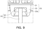
- FIG. 9 is a plan diagram illustrating an example embodiment in which a barrier 30 includes a snap portion 32 in a battery cell assembly 1.
- the support tab 22 of the battery cell assembly 1 in an example embodiment may include a pair of side tabs 23 protruding to oppose both side surfaces of the end of the barrier 30, respectively.
- the barrier 30 may include a barrier plate 31 and a snap portion 32.
- the barrier plate 31 may be disposed to oppose the side surface of the battery cell 10.
- the snap portion 32 may protrude from both sides of the end of the barrier plate 31 so as to be caught by the hooks 23a formed on the internal surfaces of the pair of side tabs 23.
- the snap portion 32 of the barrier 30 and the hook 23a of the bus-bar assembly 20 may be configured to be fastened to each other by a snapping operation. Accordingly, the bus-bar assembly 20 may be horizontally moved in the direction of the stack in which the battery cells 10 and the barrier 30 are stacked and may be fastened to the barrier 30.
- the snap portion 32 of the battery cell assembly 1 in an example embodiment may have a front surface facing the bus-bar assembly 20 to be tapered.
- the tapered shape of the snap portion 32 may be of the example in which the bus-bar assembly 20 is horizontally moved and fastened.
- the tapered shape of the snap portion 32 may be formed on a surface disposed in the other direction.
- FIG. 10A and 10B are perspective diagrams illustrating an example embodiment in which an electrode lead 11 is bent in a battery cell assembly 1.
- the electrode lead 11 of the battery cell assembly 1 in an example embodiment may penetrate through the lead hole 21a formed in the bus-bar assembly 20, may be bent, and may be welded to the bus-bar 21b of the bus-bar assembly 20, and the first electrode lead 11a disposed on one end of the bus-bar 21b may be bent in a direction opposite to the second electrode lead 11b, which is the other electrode lead 11.
- the electrode lead 11 may be configured to be bent after penetrating through the lead hole 21a, such that the space occupied by the battery cell assembly 1 may be reduced.
- the electrode lead 11 may be configured to be bent after penetrating through the lead hole 21a, such that the region in which the bent electrode lead and the bus-bar are in electrically contact with each other may increase, thereby reducing electrical resistance.
- the bus-bar assembly 20 and the battery cell 10 may be firmly coupled to each other.
- the first electrode lead 11a disposed on one end of the bus-bar 21b of the bus-bar assembly 20 may be bent in a direction opposite to the second electrode lead 11b, which is the other electrode lead 11, and may partially overlap as in FIG. 10B .
- the region occupied by the bus-bar 21b electrically fastened to the bent electrode lead 11 may be reduced, such that the space occupied by the battery cell assembly may be reduced, and a compact structure may be implemented.
- FIG. 11 is a plan diagram illustrating an example embodiment of a battery back.
- FIG. 12 is a diagram illustrating an example embodiment of a battery back, viewed from the side.
- a battery pack may include a plurality of battery cell assemblies 1 and a pack housing 2 for accommodating the plurality of battery cell assemblies 1.
- the battery cell assembly 1 may include a plurality of battery cells 10 including an electrode lead 11, a bus-bar assembly 20 coupled to the electrode lead 11, and a barrier disposed between the plurality of battery cells 10, opposing the battery cell 10, and one end of the barrier being fastened to the bus-bar assembly 20.
- the process of manufacturing the battery cell assembly 1 as a battery module may not be performed, and the battery cell assembly 1 may be installed in an electrical car in the form of a battery pack (cell to pack; CTP), such that electrical capacity of the battery pack may increase.
- CTP battery pack
- the space used for the lower case may be removed, and the size of the battery cell 10 may increase instead, such that overall electrical capacity of the battery pack may increase.
- the battery cell 10 of the battery pack may be seated on a thermal conductive material 2a applied to the pack housing 2.
- the thermal conductive material 2a may be interposed between the battery cell assembly 1 and the lower member of the pack housing 2 to cool the heat generated by the battery cell assembly 1
- the battery cell 10 having a three-sided sealing structure may be used.
- the three-sided sealing structure may complete the battery cell 10 by sealing (sealing by thermal bonding) only three surfaces (left, right, and upper surfaces) of the pouch accommodating the electrode assembly, and since the other surface (bottom surface), which is not necessary to be sealed, may be formed to have a contact area greater than that of the sealed three surfaces, and accordingly, the other surface (bottom surface) not sealed may be in direct contact with the thermal conductive material 2a, such that thermal emission efficiency may improve.
- the battery cell assembly and a battery pack including the same may have an effect of addressing the issue in which the battery cells may consecutively explode by flames or a gas generated by the explosion of one of the battery cells.
- the barrier may be easily installed.
- the overall capacity of the battery pack including the plurality of battery cell assemblies may increase.
Landscapes
- Chemical & Material Sciences (AREA)
- Chemical Kinetics & Catalysis (AREA)
- Electrochemistry (AREA)
- General Chemical & Material Sciences (AREA)
- Engineering & Computer Science (AREA)
- Aviation & Aerospace Engineering (AREA)
- Connection Of Batteries Or Terminals (AREA)
Applications Claiming Priority (1)
| Application Number | Priority Date | Filing Date | Title |
|---|---|---|---|
| KR1020210023470A KR102945306B1 (ko) | 2021-02-22 | 2021-02-22 | 배터리 셀 어셈블리 및 이를 포함하는 배터리 팩 |
Publications (2)
| Publication Number | Publication Date |
|---|---|
| EP4047731A2 true EP4047731A2 (fr) | 2022-08-24 |
| EP4047731A3 EP4047731A3 (fr) | 2022-11-16 |
Family
ID=80775310
Family Applications (1)
| Application Number | Title | Priority Date | Filing Date |
|---|---|---|---|
| EP22157694.5A Pending EP4047731A3 (fr) | 2021-02-22 | 2022-02-21 | Ensemble cellule de batterie et bloc-batterie le comprenant |
Country Status (4)
| Country | Link |
|---|---|
| US (2) | US12482900B2 (fr) |
| EP (1) | EP4047731A3 (fr) |
| KR (2) | KR102945306B1 (fr) |
| CN (1) | CN114976413A (fr) |
Families Citing this family (14)
| Publication number | Priority date | Publication date | Assignee | Title |
|---|---|---|---|---|
| KR102380342B1 (ko) * | 2022-03-07 | 2022-03-30 | 주식회사 서연이화 | 파형 게이지바가 적용된 전기차용 배터리 모듈 |
| KR20240041431A (ko) * | 2022-09-23 | 2024-04-01 | 주식회사 엘지에너지솔루션 | 배터리 모듈 및 이를 포함하는 배터리 팩 |
| EP4401191B1 (fr) * | 2022-12-02 | 2025-11-19 | Lg Energy Solution, Ltd. | Module de batterie |
| KR102843540B1 (ko) * | 2022-12-02 | 2025-08-08 | 엔브이에이치코리아(주) | 배터리용 써멀베리어 |
| KR102910589B1 (ko) * | 2022-12-02 | 2026-01-12 | 주식회사 엘지에너지솔루션 | 배터리 모듈 |
| WO2024136188A1 (fr) * | 2022-12-22 | 2024-06-27 | 주식회사 엘지에너지솔루션 | Bloc-batterie et système de stockage d'énergie le comprenant |
| KR20250007221A (ko) * | 2023-07-05 | 2025-01-14 | 주식회사 엘지에너지솔루션 | 배터리 모듈 그리고 이를 포함하는 배터리 팩 및 자동차 |
| KR20250010416A (ko) * | 2023-07-12 | 2025-01-21 | 주식회사 엘지에너지솔루션 | 배터리 모듈, 이를 포함하는 배터리 팩 및 자동차 |
| KR20250048912A (ko) * | 2023-10-04 | 2025-04-11 | 에스케이온 주식회사 | 배터리조립체 |
| KR20250064340A (ko) * | 2023-11-02 | 2025-05-09 | 주식회사 엘지에너지솔루션 | 열 전파 방지 전지 모듈 |
| KR20250074178A (ko) * | 2023-11-20 | 2025-05-27 | 주식회사 엘지에너지솔루션 | 열 전파가 방지되는 전지 모듈 |
| KR102925813B1 (ko) * | 2023-12-22 | 2026-02-10 | 주식회사 엘지에너지솔루션 | 압축 패드, 전지셀 스택 및 이를 포함하는 전지 모듈 |
| KR20250127542A (ko) * | 2024-02-19 | 2025-08-26 | 에스케이온 주식회사 | 배터리 모듈 |
| KR20260044523A (ko) * | 2024-09-26 | 2026-04-02 | 주식회사 엘지에너지솔루션 | 배터리 팩 |
Family Cites Families (17)
| Publication number | Priority date | Publication date | Assignee | Title |
|---|---|---|---|---|
| KR101326182B1 (ko) | 2010-12-28 | 2013-11-07 | 주식회사 엘지화학 | 외장부재와 카트리지를 포함하는 단위모듈에 기반한 전지모듈 |
| KR101127275B1 (ko) * | 2011-06-10 | 2012-04-02 | 김성태 | 배터리용 트레이 |
| US9666843B2 (en) * | 2014-07-30 | 2017-05-30 | Ford Global Technologies, Llc | Array frame design for electrified vehicle battery arrays |
| JP6794617B2 (ja) | 2015-09-18 | 2020-12-02 | 株式会社Gsユアサ | 蓄電装置 |
| BR112018006982A2 (pt) | 2015-11-05 | 2018-10-16 | Lg Chem, Ltd. | módulo de bateria |
| KR102036085B1 (ko) * | 2016-12-23 | 2019-10-24 | 에스케이이노베이션 주식회사 | 이차 전지 모듈 |
| KR102258817B1 (ko) * | 2017-04-25 | 2021-06-07 | 주식회사 엘지에너지솔루션 | 배터리 모듈, 이러한 배터리 모듈을 포함하는 배터리 팩 및 이러한 배터리 팩을 포함하는 자동차 |
| CN109428023B (zh) * | 2017-08-31 | 2024-04-16 | 宁德时代新能源科技股份有限公司 | 固定架、电池单元以及电池模组 |
| CN109994798B (zh) | 2017-12-26 | 2025-08-15 | Sk新能源株式会社 | 电池模块及其制造方法 |
| DE102018133391A1 (de) | 2017-12-26 | 2019-06-27 | Sk Innovation Co., Ltd. | Batteriemodul und Herstellungsverfahren desselben |
| KR102282482B1 (ko) * | 2018-02-06 | 2021-07-26 | 주식회사 엘지에너지솔루션 | 배터리 모듈 및 이를 포함하는 배터리 팩 |
| US10971786B2 (en) * | 2018-04-13 | 2021-04-06 | GM Global Technology Operations LLC | Isolative shield with positional control features for welded flexible cell tabs in an HV battery cell stack |
| KR102703855B1 (ko) * | 2018-08-21 | 2024-09-05 | 에스케이온 주식회사 | 배터리 모듈 및 이의 제조방법 |
| KR102380225B1 (ko) * | 2019-03-06 | 2022-03-28 | 주식회사 엘지에너지솔루션 | 화염의 외부 노출을 방지할 수 있는 구조를 갖는 ess 모듈 및 이를 포함하는 배터리 팩 |
| CN111668404B (zh) * | 2019-03-07 | 2024-12-03 | 宁德时代新能源科技股份有限公司 | 一种电池模块及电池包 |
| KR102750490B1 (ko) | 2019-03-15 | 2025-01-03 | 주식회사 엘지에너지솔루션 | 전지 모듈 및 그 제조 방법 |
| KR102748983B1 (ko) * | 2019-07-03 | 2024-12-30 | 주식회사 엘지에너지솔루션 | 방염 플레이트를 구비한 배터리 모듈, 이를 포함하는 배터리 랙 및 전력 저장 장치 |
-
2021
- 2021-02-22 KR KR1020210023470A patent/KR102945306B1/ko active Active
-
2022
- 2022-02-21 CN CN202210154648.9A patent/CN114976413A/zh active Pending
- 2022-02-21 EP EP22157694.5A patent/EP4047731A3/fr active Pending
- 2022-02-21 US US17/676,479 patent/US12482900B2/en active Active
-
2025
- 2025-10-29 US US19/372,864 patent/US20260058323A1/en active Pending
-
2026
- 2026-03-06 KR KR1020260040785A patent/KR20260048199A/ko active Pending
Also Published As
| Publication number | Publication date |
|---|---|
| KR102945306B1 (ko) | 2026-03-30 |
| KR20220119956A (ko) | 2022-08-30 |
| EP4047731A3 (fr) | 2022-11-16 |
| KR20260048199A (ko) | 2026-04-09 |
| US12482900B2 (en) | 2025-11-25 |
| US20220271395A1 (en) | 2022-08-25 |
| CN114976413A (zh) | 2022-08-30 |
| US20260058323A1 (en) | 2026-02-26 |
Similar Documents
| Publication | Publication Date | Title |
|---|---|---|
| US12482900B2 (en) | Battery cell assembly and battery pack including the same | |
| US20240363944A1 (en) | Battery module | |
| KR101447062B1 (ko) | 전지모듈 및 이를 포함하는 전지팩 | |
| CN112993458A (zh) | 电池模块 | |
| US12230819B2 (en) | Battery module and battery pack including the same | |
| KR102885424B1 (ko) | 인근 모듈로의 가스 이동을 방지할 수 있는 전지 모듈 | |
| US11984615B2 (en) | Battery module with flame or gas discharge path | |
| KR20210077416A (ko) | 배터리 모듈 | |
| EP4191750B1 (fr) | Bloc-batterie ayant des performances de refroidissement améliorées et dispositif le comprenant | |
| JP2023543879A (ja) | バッテリーパック及びそれを含む自動車 | |
| US20220021073A1 (en) | Battery module | |
| US20250329852A1 (en) | Battery Pack | |
| KR102799774B1 (ko) | 배터리 팩 및 이를 포함하는 자동차 | |
| US20230238601A1 (en) | Pouch-type secondary battery and battery module including the same | |
| EP4087036B1 (fr) | Module de batterie et bloc-batterie le comprenant | |
| EP4030536A1 (fr) | Module de batterie | |
| KR20230077873A (ko) | 전지 모듈 | |
| US20250300276A1 (en) | Battery module and battery pack including the same | |
| US12362413B2 (en) | Battery cell, and battery module, battery pack and vehicle including the same | |
| US20240387937A1 (en) | Battery device | |
| US20260142293A1 (en) | Eco-friendly power source such as battery module for a transportation vehicle | |
| US20240072347A1 (en) | Eco-friendly power source such as battery module for a transportation vehicle | |
| US20250087830A1 (en) | Battery module | |
| CN118541868A (zh) | 电池单体组件、包括该电池单体组件的电池组和车辆 | |
| KR20250099982A (ko) | 전지팩 및 이를 포함하는 디바이스 |
Legal Events
| Date | Code | Title | Description |
|---|---|---|---|
| PUAI | Public reference made under article 153(3) epc to a published international application that has entered the european phase |
Free format text: ORIGINAL CODE: 0009012 |
|
| STAA | Information on the status of an ep patent application or granted ep patent |
Free format text: STATUS: THE APPLICATION HAS BEEN PUBLISHED |
|
| AK | Designated contracting states |
Kind code of ref document: A2 Designated state(s): AL AT BE BG CH CY CZ DE DK EE ES FI FR GB GR HR HU IE IS IT LI LT LU LV MC MK MT NL NO PL PT RO RS SE SI SK SM TR |
|
| PUAL | Search report despatched |
Free format text: ORIGINAL CODE: 0009013 |
|
| AK | Designated contracting states |
Kind code of ref document: A3 Designated state(s): AL AT BE BG CH CY CZ DE DK EE ES FI FR GB GR HR HU IE IS IT LI LT LU LV MC MK MT NL NO PL PT RO RS SE SI SK SM TR |
|
| RIC1 | Information provided on ipc code assigned before grant |
Ipc: H01M 50/293 20210101ALI20221010BHEP Ipc: H01M 50/291 20210101ALI20221010BHEP Ipc: H01M 50/262 20210101ALI20221010BHEP Ipc: H01M 50/211 20210101AFI20221010BHEP |
|
| STAA | Information on the status of an ep patent application or granted ep patent |
Free format text: STATUS: REQUEST FOR EXAMINATION WAS MADE |
|
| 17P | Request for examination filed |
Effective date: 20230516 |
|
| RBV | Designated contracting states (corrected) |
Designated state(s): AL AT BE BG CH CY CZ DE DK EE ES FI FR GB GR HR HU IE IS IT LI LT LU LV MC MK MT NL NO PL PT RO RS SE SI SK SM TR |
|
| P01 | Opt-out of the competence of the unified patent court (upc) registered |
Effective date: 20230602 |
|
| STAA | Information on the status of an ep patent application or granted ep patent |
Free format text: STATUS: EXAMINATION IS IN PROGRESS |
|
| 17Q | First examination report despatched |
Effective date: 20260312 |