EP4048031B1 - Treiber für beleuchtungsmittel - Google Patents
Treiber für beleuchtungsmittel Download PDFInfo
- Publication number
- EP4048031B1 EP4048031B1 EP21157746.5A EP21157746A EP4048031B1 EP 4048031 B1 EP4048031 B1 EP 4048031B1 EP 21157746 A EP21157746 A EP 21157746A EP 4048031 B1 EP4048031 B1 EP 4048031B1
- Authority
- EP
- European Patent Office
- Prior art keywords
- driver
- voltage
- control circuit
- signal
- frequency
- Prior art date
- Legal status (The legal status is an assumption and is not a legal conclusion. Google has not performed a legal analysis and makes no representation as to the accuracy of the status listed.)
- Active
Links
Images



Classifications
-
- H—ELECTRICITY
- H05—ELECTRIC TECHNIQUES NOT OTHERWISE PROVIDED FOR
- H05B—ELECTRIC HEATING; ELECTRIC LIGHT SOURCES NOT OTHERWISE PROVIDED FOR; CIRCUIT ARRANGEMENTS FOR ELECTRIC LIGHT SOURCES, IN GENERAL
- H05B47/00—Circuit arrangements for operating light sources in general, i.e. where the type of light source is not relevant
- H05B47/10—Controlling the light source
- H05B47/105—Controlling the light source in response to determined parameters
-
- H—ELECTRICITY
- H05—ELECTRIC TECHNIQUES NOT OTHERWISE PROVIDED FOR
- H05B—ELECTRIC HEATING; ELECTRIC LIGHT SOURCES NOT OTHERWISE PROVIDED FOR; CIRCUIT ARRANGEMENTS FOR ELECTRIC LIGHT SOURCES, IN GENERAL
- H05B45/00—Circuit arrangements for operating light-emitting diodes [LED]
- H05B45/30—Driver circuits
- H05B45/37—Converter circuits
- H05B45/3725—Switched mode power supply [SMPS]
- H05B45/382—Switched mode power supply [SMPS] with galvanic isolation between input and output
-
- H—ELECTRICITY
- H05—ELECTRIC TECHNIQUES NOT OTHERWISE PROVIDED FOR
- H05B—ELECTRIC HEATING; ELECTRIC LIGHT SOURCES NOT OTHERWISE PROVIDED FOR; CIRCUIT ARRANGEMENTS FOR ELECTRIC LIGHT SOURCES, IN GENERAL
- H05B45/00—Circuit arrangements for operating light-emitting diodes [LED]
- H05B45/10—Controlling the intensity of the light
- H05B45/14—Controlling the intensity of the light using electrical feedback from LEDs or from LED modules
-
- H—ELECTRICITY
- H05—ELECTRIC TECHNIQUES NOT OTHERWISE PROVIDED FOR
- H05B—ELECTRIC HEATING; ELECTRIC LIGHT SOURCES NOT OTHERWISE PROVIDED FOR; CIRCUIT ARRANGEMENTS FOR ELECTRIC LIGHT SOURCES, IN GENERAL
- H05B45/00—Circuit arrangements for operating light-emitting diodes [LED]
- H05B45/30—Driver circuits
- H05B45/37—Converter circuits
- H05B45/3725—Switched mode power supply [SMPS]
-
- G—PHYSICS
- G01—MEASURING; TESTING
- G01R—MEASURING ELECTRIC VARIABLES; MEASURING MAGNETIC VARIABLES
- G01R19/00—Arrangements for measuring currents or voltages or for indicating presence or sign thereof
- G01R19/165—Indicating that current or voltage is either above or below a predetermined value or within or outside a predetermined range of values
- G01R19/16533—Indicating that current or voltage is either above or below a predetermined value or within or outside a predetermined range of values characterised by the application
- G01R19/16538—Indicating that current or voltage is either above or below a predetermined value or within or outside a predetermined range of values characterised by the application in AC or DC supplies
- G01R19/16547—Indicating that current or voltage is either above or below a predetermined value or within or outside a predetermined range of values characterised by the application in AC or DC supplies voltage or current in AC supplies
-
- H—ELECTRICITY
- H02—GENERATION; CONVERSION OR DISTRIBUTION OF ELECTRIC POWER
- H02J—ELECTRIC POWER NETWORKS; CIRCUIT ARRANGEMENTS OR SYSTEMS FOR SUPPLYING OR DISTRIBUTING ELECTRIC POWER; SYSTEMS FOR STORING ELECTRIC ENERGY
- H02J9/00—Circuit arrangements for emergency or stand-by power supply, e.g. for emergency lighting
- H02J9/02—Circuit arrangements for emergency or stand-by power supply, e.g. for emergency lighting in which an auxiliary distribution system and its associated lamps are brought into service
Definitions
- DC/AC detection circuitries for driver for lighting means are known as such. They often rely on a comparison of the input AC voltage with threshold values, so that the presence or non-presence of the input voltage crossing the threshold values can be used for detecting the lack of an AC voltage or the presence of a DC voltage, for example, for emergency lighting devices.
- WO 2011/021120 A2 discloses a known driver for lighting means being capable of converting an analog voltage signal corresponding to the line voltage to digital values indicating a waveform of the line voltage, calculating slopes corresponding to rising edges of the waveform using select values of the digital values, and determining a value of the line voltage based on the calculated slopes.
- US 2021/006168 A1 discloses a known isolated converter having a detection circuitry being arranged on a secondary side of the isolated converter.
- JP 2015-023609 A discloses a known isolated converter having a detection circuitry being arranged on a primary side of the isolated converter.
- Such emergency lighting devices are intended to be activated when the conventional lighting is no longer operative, because the mains voltage supplied to the conventional lighting device is no longer available or malfunctions.
- An emergency lighting device is typically powered by a battery or other energy storage device.
- a conventional lighting device is controlled by an on/off switch by means of which a user (or control system) can control whether the lighting is illuminated or not.
- the emergency lighting device is intended to be automatically illuminated when the absence of mains power or the malfunction of mains power for the conventional lighting device is detected in some way.
- a lighting system comprising an emergency lighting device and a conventional lighting device may be considered to have two operating modes.
- a normal mode when the direct mains supply is operating, normally (within the normal voltage range), a switched mains input, controlled by an on/off switch, is monitored, and the lamp is illuminated or extinguished in dependence upon the switched mains input.
- the lamp In an emergency mode, when the mains supply is not available or is malfunctioning (is outside the normal voltage range), the lamp is illuminated automatically, irrespective of the status of the switched mains input, using power from a battery or other storage element.
- the object of the present disclosure is achieved by a driver for an LED load according to claim 1.
- the disclosure relates to a driver for an LED load, comprising: input terminals for an optionally rectified AC voltage or AC voltage or DC voltage; output terminals for supplying the LED load, a detection circuitry connected to the input terminals, configured to obtain a signal representing a frequency of the AC voltage and an amplitude of a peak of each cycle of the AC voltage, and a control circuit being connected to the detection circuitry and supplied with said signal.
- the driver comprises a switched isolated converter, wherein the control circuit is arranged on a secondary side of the isolated converter, and the detection circuitry is arranged on a primary side of the isolated converter.
- the detection circuitry comprises a reference diode being configured to compare the AC voltage with a defined threshold voltage, and said signal includes timings of the AC voltage crossing the threshold value.
- control circuit is configured to adapt an operation parameter of the driver depending on the signal supplied to the control circuit.
- control circuit is configured to send out an information derived from the signal over a wire-bound or a wireless interface of the driver.
- a driver 100 for lighting means is shown.
- the driver for lighting means 100 comprises:
- the frequency of the peak of threshold crossing events can be used in order to have an information as to the frequency of the AC voltage.
- the duty cycle (T on time) of the time periods, during which the supplied AC voltage is higher than a given threshold value can be used by the control circuit in order to determine, for example, using an analytical function or a look-up table, the mains voltage peak value at a given frequency.
- Information as to the mains voltage amplitude and the frequency can be used, for example, to change operating parameters of the driving circuitry.
- One example is the switching from regular lighting operation to an emergency lighting operation mode as described above, wherein the lighting means are supplied off a DC voltage, e.g. supplied by a central or local battery.
- this information can be send out, for example, upon request over a bus communication, such as, for example, a DALI bus.
- a bus communication such as, for example, a DALI bus.
- the circuit shown in Fig. 2 can be used as detection circuit 102 to detect, for example, a mains state (AC, DC or no mains).
- the mains voltage is divided by a resistive divider having resistors R100, R101 and R102 and fed to a threshold element, such as e.g. a reference diode. If the voltage is higher than the threshold voltage implemented by the diode, the diode conducts.
- the output signal of the threshold element can be transmitted in a galvanically isolating manner.
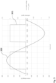
- the diode current flows through a LED of an optocoupler U100 so that the photo transistor of U100 conducts. On the secondary side of the optocoupler, this leads to the signal AC shown in Fig. 3 , wherein the curve 300 represents a mains voltage and the curve 301 represents a reference signal 301.
- the pulse width of the on pulse has to be counted.
- the pulse width is relating to the peak voltage of the input signal and, therefore, also to the effective mains voltage.
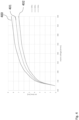
- a look-up table in the microcontroller or control circuit 103 can give the resulting input voltage for one specific frequency, as shown in Fig. 4 , wherein on times are shown as a function of mains voltage.
- the frequency is 50 Hz
- the frequency is 55 Hz
- the frequency is 60 Hz.
- the mains voltage can be scaled simply by the factor of the frequency given in the look-up table over the measured frequency (f_lookuptable / f_measured).
- each device itself can be calibrated, such that the curve stored in the look-up table actually corresponds to that specific device.
- Fig. 5 shows a system 500 comprising a driver 100 for lighting means according to an embodiment.
- the system 500 shown in Fig. 5 comprises an LED driver 100 with a circuitry and frequency/amplitude evaluation as described before. Furthermore, the system 500 comprises a DALI control unit 501, which pulls the information from the driver 100 and may be adapted to send it to a data gathering/processing unit 502, which might be a central unit of a building in order, for example, to determine the power consumption of different appliances in a building.
- a DALI control unit 501 which pulls the information from the driver 100 and may be adapted to send it to a data gathering/processing unit 502, which might be a central unit of a building in order, for example, to determine the power consumption of different appliances in a building.
- the LED driver 100 is configured to measure, for example, the mains data and the DALI control 501 is configured to query the mains data, such as mains voltage, mains current, mains power, mains frequency, etc.
- mains data such as mains voltage, mains current, mains power, mains frequency, etc.
- Those data can, then, be used by any algorithm for further data analysis (e.g., tracking power consumption for calculating energy cost).
- This algorithm can be cloud based or local.
- Communication protocols such as e.g. "DALI 2 extensions” may command mains voltage and frequency measurements to be executed by the driver, e.g. triggered by a (e.g. extended) DALI command over a bus interface of the driver.
- the driver may be an isolated driver.
- the isolation can be implemented by a transformer such as e.g. the transformer of a switched isolated converter, such as e.g. a flyback converter.
Landscapes
- Circuit Arrangement For Electric Light Sources In General (AREA)
Claims (12)
- Treiber (100) für eine LED-Last (105), umfassend:- Eingangsanschlüsse(101a, 101b) für eine Wechselspannung;- Ausgangsanschlüsse (104a, 104b) zum Versorgen der LED-Last (105),- eine Detektionsschaltlogik (102), die konfiguriert ist, um ein Signal, das eine Frequenz der Wechselspannung und eine Amplitude einer Spitze jedes Zyklus der Wechselspannung darstellt, zu erhalten, und- eine Steuerschaltung (103), die mit der Detektionsschaltlogik (102) verbunden ist und mit dem Signal versorgt wird,wobei der Treiber (100) einen geschalteten isolierten Wandler umfasst,wobei die Steuerschaltung (103) auf einer Sekundärseite des geschalteten isolierten Wandlers arrangiert ist,wobei die Detektionsschaltlogik (102) eine Referenzdiode, die konfiguriert ist, um die Wechselspannung mit einer definierten Schwellenwertspannung zu vergleichen, umfasst, undwobei das Signal Zeitpunkte, zu denen die Wechselspannung die Schwellenwertspannung überschreitet, einschließt,dadurch gekennzeichnet, dass:
die Detektionsschaltung (102) mit den Eingangsanschlüssen (101a, 101b) verbunden ist, wobei die Detektionsschaltung (102) auf einer Primärseite des geschalteten isolierten Wandlers arrangiert ist. - Treiber (100) nach Anspruch 1, wobei die Steuerschaltung (103) konfiguriert ist, um einen Betriebsparameter des Treibers (100) abhängig von dem Signal mit dem die Steuerschaltung (103) versorgt wird, anzupassen.
- Treiber (100) nach Anspruch 1 oder 2, wobei die Steuerschaltung (103) konfiguriert ist, um eine Information, die aus dem Signal abgeleitet wird, über eine drahtgebundene oder eine drahtlose Schnittstelle des Treibers (100) auszusenden.
- Treiber (100) nach einem der vorstehenden Ansprüche, wobei die Steuerschaltung (103) konfiguriert ist, um auf das Signal durch Schalten eines Betriebs der LED-Last (105) auf einen Notbeleuchtungsmittelbetrieb zu reagieren.
- Treiber (100) nach einem der vorstehenden Ansprüche, wobei die Detektionsschaltlogik (102) konfiguriert ist, um eine Schwellenwertüberschreitung einer steigenden Flanke der Wechselspannung zu bestimmen, um das Signal, das die Frequenz der Wechselspannung darstellt, zu erzeugen.
- Treiber (100) nach Anspruch 5, wobei die Detektionsschaltlogik (102) konfiguriert ist, um eine Zeitdauer zwischen der Schwellenwertüberschreitung der steigenden Flanke und einer Schwellenwertüberschreitung einer fallenden Flanke der Wechselspannung zu bestimmen, um das Signal, das die Spitzenamplitude der Wechselspannung darstellt, zu erzeugen.
- Treiber (100) nach Anspruch 6, wobei die Steuerschaltung (103) konfiguriert ist, um auf eine Nachschlagetabelle zuzugreifen, um die Zeitdauer zwischen der Schwellenwertüberschreitung der steigenden Flanke und der Schwellenwertüberschreitung der fallenden Flanke der Wechselspannung in einen Spitzenspannungswert der Wechselspannung umzuwandeln.
- Treiber (100) nach einem der vorstehenden Ansprüche, wobei der geschaltete isolierte Wandler einen Sperrwandler umfasst.
- Treiber (100) nach einem der vorstehenden Ansprüche, der ferner arrangiert ist, um ein Steuersignal an einen Schalter eines geschalteten Wandlers, wie etwa z.B. einen Abwärts- oder Aufwärtswandler, der auf der Sekundärseite des geschalteten isolierten Wandlers arrangiert ist, auszugeben.
- Treiber (100) nach einem der vorstehenden Ansprüche,
wobei die Steuerschaltung (103) eine Busschnittstelle, z.B. eine DALI-Schnittstelle, umfasst. - System (500), umfassend eine Zentraleinheitsschaltung (502) und einen Treiber (100) nach einem der Ansprüche 1 bis 10, wobei die Zentraleinheitsschaltung (502) mit dem Treiber (100) verbunden ist, wobei der Treiber (100) konfiguriert ist, um der Zentraleinheit (502) die Spitzenspannung und die Frequenz der Wechselspannung, mit der der Treiber (100) versorgt wird, zu übermitteln.
- Notbeleuchtungseinheit, umfassend einen Treiber (100) nach einem der Ansprüche 1 bis 10 sowie eine LED-Last (105), die konfiguriert ist, um durch den Treiber (100) versorgt zu werden.
Priority Applications (4)
| Application Number | Priority Date | Filing Date | Title |
|---|---|---|---|
| EP21157746.5A EP4048031B1 (de) | 2021-02-18 | 2021-02-18 | Treiber für beleuchtungsmittel |
| CN202280015010.5A CN116848955A (zh) | 2021-02-18 | 2022-02-07 | 用于照明装置的驱动器 |
| US18/261,543 US12336071B2 (en) | 2021-02-18 | 2022-02-07 | Driver for lighting means |
| PCT/EP2022/052829 WO2022175125A1 (en) | 2021-02-18 | 2022-02-07 | Driver for lighting means |
Applications Claiming Priority (1)
| Application Number | Priority Date | Filing Date | Title |
|---|---|---|---|
| EP21157746.5A EP4048031B1 (de) | 2021-02-18 | 2021-02-18 | Treiber für beleuchtungsmittel |
Publications (2)
| Publication Number | Publication Date |
|---|---|
| EP4048031A1 EP4048031A1 (de) | 2022-08-24 |
| EP4048031B1 true EP4048031B1 (de) | 2025-04-09 |
Family
ID=74668626
Family Applications (1)
| Application Number | Title | Priority Date | Filing Date |
|---|---|---|---|
| EP21157746.5A Active EP4048031B1 (de) | 2021-02-18 | 2021-02-18 | Treiber für beleuchtungsmittel |
Country Status (4)
| Country | Link |
|---|---|
| US (1) | US12336071B2 (de) |
| EP (1) | EP4048031B1 (de) |
| CN (1) | CN116848955A (de) |
| WO (1) | WO2022175125A1 (de) |
Citations (2)
| Publication number | Priority date | Publication date | Assignee | Title |
|---|---|---|---|---|
| JP2015023609A (ja) * | 2013-07-16 | 2015-02-02 | ローム株式会社 | Ac/dcコンバータおよびその制御回路、電源アダプタおよび電子機器 |
| US20210006168A1 (en) * | 2018-02-28 | 2021-01-07 | Eldolab Holding B.V. | Power converter for led |
Family Cites Families (9)
| Publication number | Priority date | Publication date | Assignee | Title |
|---|---|---|---|---|
| US8222832B2 (en) * | 2009-07-14 | 2012-07-17 | Iwatt Inc. | Adaptive dimmer detection and control for LED lamp |
| JP5436079B2 (ja) * | 2009-07-16 | 2014-03-05 | Jx日鉱日石エネルギー株式会社 | 軽油組成物 |
| TW201119504A (en) * | 2009-08-18 | 2011-06-01 | Koninkl Philips Electronics Nv | Method and apparatus providing universal voltage input for solid state light fixtures |
| EP2489242A1 (de) * | 2009-10-14 | 2012-08-22 | Tridonic UK Limited | Phasenschnittverdunklung von leds |
| US8729826B2 (en) * | 2010-06-07 | 2014-05-20 | Greenwave Reality, Pte, Ltd. | Dual-mode dimming of a light |
| JP5828103B2 (ja) * | 2010-12-20 | 2015-12-02 | パナソニックIpマネジメント株式会社 | Led点灯装置及びそれを用いた照明器具 |
| GB201204106D0 (en) * | 2012-03-08 | 2012-04-18 | Tridonic Uk Ltd | Lamp unit power supply system |
| CN103925480A (zh) * | 2014-05-08 | 2014-07-16 | 浙江中博光电科技有限公司 | 便携式led应急灯及其控制方法 |
| CN211785749U (zh) * | 2020-01-06 | 2020-10-27 | 佛山市云米电器科技有限公司 | 一种交流电检测电路和家用电器 |
-
2021
- 2021-02-18 EP EP21157746.5A patent/EP4048031B1/de active Active
-
2022
- 2022-02-07 WO PCT/EP2022/052829 patent/WO2022175125A1/en not_active Ceased
- 2022-02-07 CN CN202280015010.5A patent/CN116848955A/zh active Pending
- 2022-02-07 US US18/261,543 patent/US12336071B2/en active Active
Patent Citations (2)
| Publication number | Priority date | Publication date | Assignee | Title |
|---|---|---|---|---|
| JP2015023609A (ja) * | 2013-07-16 | 2015-02-02 | ローム株式会社 | Ac/dcコンバータおよびその制御回路、電源アダプタおよび電子機器 |
| US20210006168A1 (en) * | 2018-02-28 | 2021-01-07 | Eldolab Holding B.V. | Power converter for led |
Also Published As
| Publication number | Publication date |
|---|---|
| CN116848955A (zh) | 2023-10-03 |
| WO2022175125A1 (en) | 2022-08-25 |
| US20240080954A1 (en) | 2024-03-07 |
| US12336071B2 (en) | 2025-06-17 |
| EP4048031A1 (de) | 2022-08-24 |
Similar Documents
| Publication | Publication Date | Title |
|---|---|---|
| US8680884B2 (en) | Fault detection circuits for switched mode power supplies and related methods of operation | |
| US9142962B2 (en) | Wall box device for managing energy | |
| US10201064B1 (en) | Power supply for a two-wire smart dimmer and lighting loads thereof | |
| US10123393B1 (en) | Power supply for a two-wire smart switch and lighting loads thereof | |
| JP2015520481A (ja) | 照明装置 | |
| CN106796254B (zh) | 供电电压探测装置和用于探测供电电压的方法 | |
| JP7066060B2 (ja) | 駆動回路及び関連ランプ | |
| CN102739057B (zh) | 初次级双反馈控制的返驰式电源转换器 | |
| US8427114B2 (en) | Apparatus for controlling LED indicator of charging status at the primary control side of an AC-DC power charger | |
| US10845425B2 (en) | Systems and methods for detecting switching circuitry failure | |
| CN102057754A (zh) | 用于将电源耦合到灯的装置 | |
| CA2973377A1 (en) | Emergency system with brown-out detection | |
| EP4048031B1 (de) | Treiber für beleuchtungsmittel | |
| US9089021B2 (en) | Controller of an AC-DC converter for LED lighting | |
| US6535405B2 (en) | Power supply device having two AC power inputs | |
| KR101705831B1 (ko) | 발광 장치를 위한 조광 장치 | |
| EP4084583B1 (de) | Schaltung und verfahren zur bestimmung einer netzspannung in einer isolierten geschalteten treibervorrichtung | |
| EP3823149A1 (de) | Isolierter primärseitiger schaltwandler | |
| JP2007200672A (ja) | 負荷制御回路及び電子式スイッチ | |
| JP6613938B2 (ja) | Led用電源装置及びled照明装置 | |
| US12484126B2 (en) | Multi-channel light-emitting diode (LED) linear driver circuit | |
| KR20130034377A (ko) | Led조명용 조명제어회로 | |
| KR20160076024A (ko) | Ac 스위치 조작에 따른 smps 2차측 dc 출력 변화를 감지하여 디밍 기능을 수행할 수 있는 컨버터 내장형 디밍 장치 | |
| JP2003047169A (ja) | 停電検知装置 | |
| JP2001176688A (ja) | 電圧共振型電源装置 |
Legal Events
| Date | Code | Title | Description |
|---|---|---|---|
| PUAI | Public reference made under article 153(3) epc to a published international application that has entered the european phase |
Free format text: ORIGINAL CODE: 0009012 |
|
| STAA | Information on the status of an ep patent application or granted ep patent |
Free format text: STATUS: THE APPLICATION HAS BEEN PUBLISHED |
|
| AK | Designated contracting states |
Kind code of ref document: A1 Designated state(s): AL AT BE BG CH CY CZ DE DK EE ES FI FR GB GR HR HU IE IS IT LI LT LU LV MC MK MT NL NO PL PT RO RS SE SI SK SM TR |
|
| STAA | Information on the status of an ep patent application or granted ep patent |
Free format text: STATUS: REQUEST FOR EXAMINATION WAS MADE |
|
| 17P | Request for examination filed |
Effective date: 20221121 |
|
| RBV | Designated contracting states (corrected) |
Designated state(s): AL AT BE BG CH CY CZ DE DK EE ES FI FR GB GR HR HU IE IS IT LI LT LU LV MC MK MT NL NO PL PT RO RS SE SI SK SM TR |
|
| STAA | Information on the status of an ep patent application or granted ep patent |
Free format text: STATUS: EXAMINATION IS IN PROGRESS |
|
| 17Q | First examination report despatched |
Effective date: 20231204 |
|
| GRAP | Despatch of communication of intention to grant a patent |
Free format text: ORIGINAL CODE: EPIDOSNIGR1 |
|
| STAA | Information on the status of an ep patent application or granted ep patent |
Free format text: STATUS: GRANT OF PATENT IS INTENDED |
|
| RIC1 | Information provided on ipc code assigned before grant |
Ipc: G01R 19/165 20060101ALI20241210BHEP Ipc: H05B 47/105 20200101ALI20241210BHEP Ipc: H02J 9/02 20060101ALI20241210BHEP Ipc: H02J 9/06 20060101ALI20241210BHEP Ipc: H05B 45/3725 20200101AFI20241210BHEP |
|
| INTG | Intention to grant announced |
Effective date: 20241219 |
|
| GRAS | Grant fee paid |
Free format text: ORIGINAL CODE: EPIDOSNIGR3 |
|
| GRAA | (expected) grant |
Free format text: ORIGINAL CODE: 0009210 |
|
| STAA | Information on the status of an ep patent application or granted ep patent |
Free format text: STATUS: THE PATENT HAS BEEN GRANTED |
|
| AK | Designated contracting states |
Kind code of ref document: B1 Designated state(s): AL AT BE BG CH CY CZ DE DK EE ES FI FR GB GR HR HU IE IS IT LI LT LU LV MC MK MT NL NO PL PT RO RS SE SI SK SM TR |
|
| REG | Reference to a national code |
Ref country code: GB Ref legal event code: FG4D |
|
| REG | Reference to a national code |
Ref country code: CH Ref legal event code: EP |
|
| P01 | Opt-out of the competence of the unified patent court (upc) registered |
Free format text: CASE NUMBER: APP_11231/2025 Effective date: 20250306 |
|
| REG | Reference to a national code |
Ref country code: DE Ref legal event code: R096 Ref document number: 602021028745 Country of ref document: DE |
|
| REG | Reference to a national code |
Ref country code: IE Ref legal event code: FG4D |
|
| REG | Reference to a national code |
Ref country code: NL Ref legal event code: MP Effective date: 20250409 |
|
| PG25 | Lapsed in a contracting state [announced via postgrant information from national office to epo] |
Ref country code: NL Free format text: LAPSE BECAUSE OF FAILURE TO SUBMIT A TRANSLATION OF THE DESCRIPTION OR TO PAY THE FEE WITHIN THE PRESCRIBED TIME-LIMIT Effective date: 20250409 |
|
| REG | Reference to a national code |
Ref country code: AT Ref legal event code: MK05 Ref document number: 1784799 Country of ref document: AT Kind code of ref document: T Effective date: 20250409 |
|
| PG25 | Lapsed in a contracting state [announced via postgrant information from national office to epo] |
Ref country code: ES Free format text: LAPSE BECAUSE OF FAILURE TO SUBMIT A TRANSLATION OF THE DESCRIPTION OR TO PAY THE FEE WITHIN THE PRESCRIBED TIME-LIMIT Effective date: 20250409 Ref country code: FI Free format text: LAPSE BECAUSE OF FAILURE TO SUBMIT A TRANSLATION OF THE DESCRIPTION OR TO PAY THE FEE WITHIN THE PRESCRIBED TIME-LIMIT Effective date: 20250409 Ref country code: PT Free format text: LAPSE BECAUSE OF FAILURE TO SUBMIT A TRANSLATION OF THE DESCRIPTION OR TO PAY THE FEE WITHIN THE PRESCRIBED TIME-LIMIT Effective date: 20250811 |
|
| REG | Reference to a national code |
Ref country code: LT Ref legal event code: MG9D |
|
| PG25 | Lapsed in a contracting state [announced via postgrant information from national office to epo] |
Ref country code: GR Free format text: LAPSE BECAUSE OF FAILURE TO SUBMIT A TRANSLATION OF THE DESCRIPTION OR TO PAY THE FEE WITHIN THE PRESCRIBED TIME-LIMIT Effective date: 20250710 Ref country code: NO Free format text: LAPSE BECAUSE OF FAILURE TO SUBMIT A TRANSLATION OF THE DESCRIPTION OR TO PAY THE FEE WITHIN THE PRESCRIBED TIME-LIMIT Effective date: 20250709 |
|
| PG25 | Lapsed in a contracting state [announced via postgrant information from national office to epo] |
Ref country code: PL Free format text: LAPSE BECAUSE OF FAILURE TO SUBMIT A TRANSLATION OF THE DESCRIPTION OR TO PAY THE FEE WITHIN THE PRESCRIBED TIME-LIMIT Effective date: 20250409 |
|
| PG25 | Lapsed in a contracting state [announced via postgrant information from national office to epo] |
Ref country code: BG Free format text: LAPSE BECAUSE OF FAILURE TO SUBMIT A TRANSLATION OF THE DESCRIPTION OR TO PAY THE FEE WITHIN THE PRESCRIBED TIME-LIMIT Effective date: 20250409 |
|
| PG25 | Lapsed in a contracting state [announced via postgrant information from national office to epo] |
Ref country code: HR Free format text: LAPSE BECAUSE OF FAILURE TO SUBMIT A TRANSLATION OF THE DESCRIPTION OR TO PAY THE FEE WITHIN THE PRESCRIBED TIME-LIMIT Effective date: 20250409 |
|
| PG25 | Lapsed in a contracting state [announced via postgrant information from national office to epo] |
Ref country code: AT Free format text: LAPSE BECAUSE OF FAILURE TO SUBMIT A TRANSLATION OF THE DESCRIPTION OR TO PAY THE FEE WITHIN THE PRESCRIBED TIME-LIMIT Effective date: 20250409 |
|
| PG25 | Lapsed in a contracting state [announced via postgrant information from national office to epo] |
Ref country code: RS Free format text: LAPSE BECAUSE OF FAILURE TO SUBMIT A TRANSLATION OF THE DESCRIPTION OR TO PAY THE FEE WITHIN THE PRESCRIBED TIME-LIMIT Effective date: 20250709 |
|
| PG25 | Lapsed in a contracting state [announced via postgrant information from national office to epo] |
Ref country code: IS Free format text: LAPSE BECAUSE OF FAILURE TO SUBMIT A TRANSLATION OF THE DESCRIPTION OR TO PAY THE FEE WITHIN THE PRESCRIBED TIME-LIMIT Effective date: 20250809 |
|
| PG25 | Lapsed in a contracting state [announced via postgrant information from national office to epo] |
Ref country code: LV Free format text: LAPSE BECAUSE OF FAILURE TO SUBMIT A TRANSLATION OF THE DESCRIPTION OR TO PAY THE FEE WITHIN THE PRESCRIBED TIME-LIMIT Effective date: 20250409 |
|
| REG | Reference to a national code |
Ref country code: DE Ref legal event code: R097 Ref document number: 602021028745 Country of ref document: DE |
|
| PG25 | Lapsed in a contracting state [announced via postgrant information from national office to epo] |
Ref country code: DK Free format text: LAPSE BECAUSE OF FAILURE TO SUBMIT A TRANSLATION OF THE DESCRIPTION OR TO PAY THE FEE WITHIN THE PRESCRIBED TIME-LIMIT Effective date: 20250409 Ref country code: SM Free format text: LAPSE BECAUSE OF FAILURE TO SUBMIT A TRANSLATION OF THE DESCRIPTION OR TO PAY THE FEE WITHIN THE PRESCRIBED TIME-LIMIT Effective date: 20250409 |
|
| PG25 | Lapsed in a contracting state [announced via postgrant information from national office to epo] |
Ref country code: CZ Free format text: LAPSE BECAUSE OF FAILURE TO SUBMIT A TRANSLATION OF THE DESCRIPTION OR TO PAY THE FEE WITHIN THE PRESCRIBED TIME-LIMIT Effective date: 20250409 |
|
| PG25 | Lapsed in a contracting state [announced via postgrant information from national office to epo] |
Ref country code: EE Free format text: LAPSE BECAUSE OF FAILURE TO SUBMIT A TRANSLATION OF THE DESCRIPTION OR TO PAY THE FEE WITHIN THE PRESCRIBED TIME-LIMIT Effective date: 20250409 |
|
| PG25 | Lapsed in a contracting state [announced via postgrant information from national office to epo] |
Ref country code: SK Free format text: LAPSE BECAUSE OF FAILURE TO SUBMIT A TRANSLATION OF THE DESCRIPTION OR TO PAY THE FEE WITHIN THE PRESCRIBED TIME-LIMIT Effective date: 20250409 |
|
| PG25 | Lapsed in a contracting state [announced via postgrant information from national office to epo] |
Ref country code: IT Free format text: LAPSE BECAUSE OF FAILURE TO SUBMIT A TRANSLATION OF THE DESCRIPTION OR TO PAY THE FEE WITHIN THE PRESCRIBED TIME-LIMIT Effective date: 20250409 |
|
| PLBE | No opposition filed within time limit |
Free format text: ORIGINAL CODE: 0009261 |
|
| STAA | Information on the status of an ep patent application or granted ep patent |
Free format text: STATUS: NO OPPOSITION FILED WITHIN TIME LIMIT |
|
| REG | Reference to a national code |
Ref country code: CH Ref legal event code: L10 Free format text: ST27 STATUS EVENT CODE: U-0-0-L10-L00 (AS PROVIDED BY THE NATIONAL OFFICE) Effective date: 20260218 |
|
| 26N | No opposition filed |
Effective date: 20260112 |
|
| PGFP | Annual fee paid to national office [announced via postgrant information from national office to epo] |
Ref country code: GB Payment date: 20260223 Year of fee payment: 6 |
|
| PGFP | Annual fee paid to national office [announced via postgrant information from national office to epo] |
Ref country code: DE Payment date: 20260220 Year of fee payment: 6 |
|
| PGFP | Annual fee paid to national office [announced via postgrant information from national office to epo] |
Ref country code: FR Payment date: 20260224 Year of fee payment: 6 |