EP4048041A1 - Conduit d'air d'armoire, ensemble armoire et onduleur photovoltaïque - Google Patents
Conduit d'air d'armoire, ensemble armoire et onduleur photovoltaïque Download PDFInfo
- Publication number
- EP4048041A1 EP4048041A1 EP22157515.2A EP22157515A EP4048041A1 EP 4048041 A1 EP4048041 A1 EP 4048041A1 EP 22157515 A EP22157515 A EP 22157515A EP 4048041 A1 EP4048041 A1 EP 4048041A1
- Authority
- EP
- European Patent Office
- Prior art keywords
- cabinet
- air
- air duct
- fan
- guiding structure
- Prior art date
- Legal status (The legal status is an assumption and is not a legal conclusion. Google has not performed a legal analysis and makes no representation as to the accuracy of the status listed.)
- Granted
Links
Images



Classifications
-
- H—ELECTRICITY
- H05—ELECTRIC TECHNIQUES NOT OTHERWISE PROVIDED FOR
- H05K—PRINTED CIRCUITS; CASINGS OR CONSTRUCTIONAL DETAILS OF ELECTRIC APPARATUS; MANUFACTURE OF ASSEMBLAGES OF ELECTRICAL COMPONENTS
- H05K7/00—Constructional details common to different types of electric apparatus
- H05K7/20—Modifications to facilitate cooling, ventilating, or heating
- H05K7/2089—Modifications to facilitate cooling, ventilating, or heating for power electronics, e.g. for inverters for controlling motor
- H05K7/20909—Forced ventilation, e.g. on heat dissipaters coupled to components
-
- H—ELECTRICITY
- H02—GENERATION; CONVERSION OR DISTRIBUTION OF ELECTRIC POWER
- H02M—APPARATUS FOR CONVERSION BETWEEN AC AND AC, BETWEEN AC AND DC, OR BETWEEN DC AND DC, AND FOR USE WITH MAINS OR SIMILAR POWER SUPPLY SYSTEMS; CONVERSION OF DC OR AC INPUT POWER INTO SURGE OUTPUT POWER; CONTROL OR REGULATION THEREOF
- H02M1/00—Details of apparatus for conversion
-
- H—ELECTRICITY
- H02—GENERATION; CONVERSION OR DISTRIBUTION OF ELECTRIC POWER
- H02M—APPARATUS FOR CONVERSION BETWEEN AC AND AC, BETWEEN AC AND DC, OR BETWEEN DC AND DC, AND FOR USE WITH MAINS OR SIMILAR POWER SUPPLY SYSTEMS; CONVERSION OF DC OR AC INPUT POWER INTO SURGE OUTPUT POWER; CONTROL OR REGULATION THEREOF
- H02M7/00—Conversion of AC power input into DC power output; Conversion of DC power input into AC power output
- H02M7/003—Constructional details, e.g. physical layout, assembly, wiring or busbar connections
-
- H—ELECTRICITY
- H02—GENERATION; CONVERSION OR DISTRIBUTION OF ELECTRIC POWER
- H02S—GENERATION OF ELECTRIC POWER BY CONVERSION OF INFRARED RADIATION, VISIBLE LIGHT OR ULTRAVIOLET LIGHT, e.g. USING PHOTOVOLTAIC [PV] MODULES
- H02S40/00—Components or accessories in combination with PV modules, not provided for in groups H02S10/00 - H02S30/00
- H02S40/30—Electrical components
- H02S40/32—Electrical components comprising DC/AC inverter means associated with the PV module itself, e.g. AC modules
-
- H—ELECTRICITY
- H05—ELECTRIC TECHNIQUES NOT OTHERWISE PROVIDED FOR
- H05K—PRINTED CIRCUITS; CASINGS OR CONSTRUCTIONAL DETAILS OF ELECTRIC APPARATUS; MANUFACTURE OF ASSEMBLAGES OF ELECTRICAL COMPONENTS
- H05K7/00—Constructional details common to different types of electric apparatus
- H05K7/20—Modifications to facilitate cooling, ventilating, or heating
- H05K7/20009—Modifications to facilitate cooling, ventilating, or heating using a gaseous coolant in electronic enclosures
- H05K7/20136—Forced ventilation, e.g. by fans
- H05K7/20145—Means for directing air flow, e.g. ducts, deflectors, plenum or guides
-
- H—ELECTRICITY
- H05—ELECTRIC TECHNIQUES NOT OTHERWISE PROVIDED FOR
- H05K—PRINTED CIRCUITS; CASINGS OR CONSTRUCTIONAL DETAILS OF ELECTRIC APPARATUS; MANUFACTURE OF ASSEMBLAGES OF ELECTRICAL COMPONENTS
- H05K7/00—Constructional details common to different types of electric apparatus
- H05K7/20—Modifications to facilitate cooling, ventilating, or heating
- H05K7/20009—Modifications to facilitate cooling, ventilating, or heating using a gaseous coolant in electronic enclosures
- H05K7/20136—Forced ventilation, e.g. by fans
- H05K7/20172—Fan mounting or fan specifications
-
- H—ELECTRICITY
- H05—ELECTRIC TECHNIQUES NOT OTHERWISE PROVIDED FOR
- H05K—PRINTED CIRCUITS; CASINGS OR CONSTRUCTIONAL DETAILS OF ELECTRIC APPARATUS; MANUFACTURE OF ASSEMBLAGES OF ELECTRICAL COMPONENTS
- H05K7/00—Constructional details common to different types of electric apparatus
- H05K7/20—Modifications to facilitate cooling, ventilating, or heating
- H05K7/2089—Modifications to facilitate cooling, ventilating, or heating for power electronics, e.g. for inverters for controlling motor
- H05K7/20909—Forced ventilation, e.g. on heat dissipaters coupled to components
- H05K7/20918—Forced ventilation, e.g. on heat dissipaters coupled to components the components being isolated from air flow, e.g. hollow heat sinks, wind tunnels or funnels
-
- H—ELECTRICITY
- H02—GENERATION; CONVERSION OR DISTRIBUTION OF ELECTRIC POWER
- H02S—GENERATION OF ELECTRIC POWER BY CONVERSION OF INFRARED RADIATION, VISIBLE LIGHT OR ULTRAVIOLET LIGHT, e.g. USING PHOTOVOLTAIC [PV] MODULES
- H02S40/00—Components or accessories in combination with PV modules, not provided for in groups H02S10/00 - H02S30/00
- H02S40/40—Thermal components
- H02S40/42—Cooling means
- H02S40/425—Cooling means using a gaseous or a liquid coolant, e.g. air flow ventilation, water circulation
Definitions
- the present application relates to the field of heat dissipation by air ducts, and in particular to a cabinet air duct.
- the present application further relates to a cabinet assembly including the above cabinet air duct, and yet relates to a photovoltaic inverter including the above cabinet assembly.
- a ventilation port is generally arranged inside the cabinet for communication with a colder atmosphere outside.
- a photovoltaic inverter is an interface between a solar power system and a power grid, and with the upcoming realization of a large-scale photovoltaic power plant getting the power on the grid at a fair price, the demand for higher power of the photovoltaic grid-connected inverter becomes stronger, and therefore, the desire for the heat dissipation of the cabinet installed therein with electrical components becomes more prominent.
- An air inlet of the conventional cabinet air duct is generally arranged at the bottom of a side wall of the cabinet, and an air outlet is arranged at the top of the same side wall as the air inlet of the cabinet.
- a fan is provided inside the air duct of the cabinet to realize flowing of the air.
- the air inlet and the air outlet are located on the same side wall of the cabinet, the air duct is likely to be short-circuited during use, thereby reducing the heat dissipation effect of the air duct of the cabinet.
- An object of the present application is to provide a cabinet air duct with improved heat dissipation effect. Another object of the present application is to provide a cabinet assembly including the above cabinet air duct. Another object of the present application is to provide a photovoltaic inverter including the above cabinet assembly.
- a cabinet air duct which includes a cabinet and an air duct arranged in the cabinet, where the cabinet is provided with an air inlet and an air outlet that are in communication with the air duct; the air inlet is arranged on a first side surface of the cabinet, the air outlet is arranged on a second side surface of the cabinet, and the first side surface and the second side surface are two opposite side surfaces of the cabinet.
- a first cavity and a second cavity sealingly isolated from the first cavity are provided in the cabinet, and the air duct is located in the first cavity.
- the first cavity and the second cavity are isolated by a heat conducting plate.
- At least two first cavities are provided, and the first cavities are in one-to-one correspondence with the air ducts.
- the cabinet air duct further includes an air inlet guiding structure connected to a side wall of the cabinet and arranged at the air inlet.
- the cabinet air duct further includes an air outlet guiding structure connected to the side wall of the cabinet and arranged at the air outlet.
- the cabinet air duct further includes a fan, wherein the fan is arranged upstream and/or downstream from a heating device along an airflow direction.
- the fan includes a first fan arranged upstream from the heating device, and the first fan is located in the air inlet guiding structure and/or located upstream from the heating device in the cabinet along the airflow direction.
- the fan includes a second fan located downstream from the heating device, and the second fan is located in the air outlet guiding structure and/or downstream from the heating device in the cabinet along the airflow direction.
- a joint of the air inlet guiding structure and the cabinet and a joint of the air outlet guiding structure and the cabinet are respectively provided with a sealing member for sealing a gap therebetween.
- the cabinet air duct further includes a ventilation protective cover for preventing impurities from entering the air duct.
- the air inlet and the air outlet are arranged at the same height.
- a cabinet assembly includes the cabinet air duct provided according to any one of the above and a cabinet door installed on the cabinet.
- a cabinet assembly includes the cabinet air duct provided according to any one of the above and a cabinet door installed on the cabinet, where the air inlet and the air outlet are both provided on the cabinet door.
- the cabinet assembly further includes the air inlet guiding structure connected to a side wall of the cabinet and arranged the air inlet, and the air outlet guiding structure connected to the cabinet and arranged at the air outlet, wherein the air inlet guiding structure and the air outlet guiding structure are both arranged on an outer surface of the cabinet door.
- one of the air inlet guiding structure and the air outlet guiding structure is arranged on a rear door of the cabinet door, and the other is arranged on a front door of the cabinet door.
- the cabinet assembly further includes a fan, wherein the fan is arranged upstream and/or downstream from a heating device along an airflow direction, and the fan is installed on the front door and/or the rear door of the cabinet door.
- a photovoltaic inverter includes the cabinet assembly described in any one of the above and a heating device installed inside the cabinet assembly.
- the cabinet air duct provided according to the present application includes a cabinet and an air duct arranged in the cabinet.
- the cabinet is provided with an air inlet and an air outlet that are in communication with the air duct.
- the air inlet is arranged on a first side surface of the cabinet
- the air outlet is arranged on a second side surface of the cabinet
- the first side surface and the second side surface are two opposite side surfaces of the cabinet.
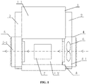
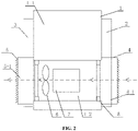
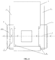
- FIGS. 1 to 10 Reference numerals in FIGS. 1 to 10 are listed as follows: 1 cabinet; 1-1 second cavity; 1-2 first cavity; 2 front door; 3 rear door; 4 air inlet guiding structure; 4-1 air inlet cavity; 5 air outlet guiding structure; 5-1 air outlet cavity; 6 fan; 7 heating device; 8 sealing member.
- a core of the present application is to provide a cabinet air duct with improved heat dissipation effect. Another core of the present application is to provide a cabinet assembly including the above cabinet air duct. Another core of the present application is to provide a photovoltaic inverter including the above cabinet assembly.
- FIGS. 1 to 10 Reference is made to FIGS. 1 to 10 .
- a cabinet air duct provided according to an embodiment of the present application includes a cabinet 1 and an air duct arranged in the cabinet 1.
- the cabinet 1 is provided with an air inlet and an air outlet that are in communication with the air duct.
- the air inlet is arranged on a first side surface of the cabinet 1, and the air outlet is arranged on a second side surface of the cabinet 1.
- the first side surface and the second side surface are two opposite side surfaces of the cabinet 1, that is, the air inlet and the air outlet are respectively arranged on two sides of the cabinet 1.
- the air duct is arranged horizontally, and the air inlet and the air outlet are symmetrically distributed on two side surfaces of the cabinet 1 about a center line of the cabinet 1.
- the air inlet is located on the first side surface of the cabinet 1
- the air outlet is located on the second side surface of the cabinet 1
- the air inlet and the air outlet are arranged on different side surfaces of the cabinet 1 to reduce the occurrence of short circuit of air at the air inlet and air outlet, thereby reducing the occurrence of a situation that the discharged hot air interferes with the entry of cold air. Therefore, the heat dissipation effect of the cabinet air duct provided according to the present application is improved.
- heating devices 7 in the cabinet 1 may all be located in the air duct. Taking into account the sealing of part of the heating devices 7, preferably, a first cavity 1-2 and a second cavity 1-1 sealingly isolated from the first cavity 1-2 are provided in the cabinet 1, and the air duct is arranged in the first cavity 1-2.
- the first cavity 1-2 and the second cavity 1-1 are isolated by a heat conducting plate. Specifically, edges of the heat conducting plate are sealed with an inner wall of the cabinet 1 by bonding.
- the shape, thickness, and material of the heat conducting plate are determined according to actual requirements, which are not specifically limited in the present application.
- At least two first cavities 1-2 are provided, and the at least two first cavities 1-2 are in one-to-one correspondence with the air ducts. That is, each of the at least two first cavities 1-2 is preferably arranged independently.
- the at least two first cavities 1-2 may be arranged horizontally, or the at least two first cavities 1-2 are arranged sequentially from top to bottom.
- the cabinet air duct further includes an air inlet guiding structure 4 connected to a side wall of the cabinet 1 and arranged at the air inlet, wherein an air inlet cavity 4-1 in communication with the air inlet is defined inside the air inlet guiding structure 4.
- the cabinet air duct further includes an air outlet guiding structure 5 connected to the cabinet 1 and arranged at the air outlet, wherein an air outlet cavity 5-1 in communication with the air outlet is defined inside the air outlet guiding structure 5.
- the cabinet air duct further includes a fan 6 arranged upstream or downstream from the heating device 7.
- the fan 6 may also be provided both upstream and downstream from the heating device 7. In a case that the fan 6 is arranged upstream from the heating device 7, the influence of hot air on the fan 6 is reduced.
- the fan 6 may be directly arranged inside the air duct.
- the fan 6 includes a first fan arranged upstream from the heating device 7, and the first fan is located in the air inlet guiding structure 4 and/or located upstream from the heating device 7 in the cabinet 1.
- One or more first fans may be provided. In a case that multiple first fans are provided, preferably, the first fans are arranged perpendicular to an airflow direction.
- the fan 6 includes a second fan arranged downstream from the heating device 7, and the second fan is located in the air outlet guiding structure 5 and/or located downstream from the heating device 7 in the cabinet 1.
- One or more second fans may be provided. In a case that multiple second fans are provided, preferably, the second fans are arranged perpendicular to the airflow direction.
- a joint of the air inlet guiding structure 4 and the cabinet 1 and a joint of the air outlet guiding structure 5 and the cabinet 1 are respectively provided with a sealing member 8 for sealing a gap therebetween.
- the sealing member 8 may be embodied as a sealant strip, or an elastic sealing member bonded to the cabinet 1.
- the sealing member 8 is configured to isolate the air inlet guiding structure 4 and the air outlet guiding structure 5 from the second cavity 1-1, so as to ensure that the airflow of the air duct will not flow into the second cavity 1-1 of the cabinet 1.
- the cabinet air duct further includes a ventilation protective cover for preventing impurities from entering the air duct.
- the ventilating protective cover may be embodies as a waterproof breathable membrane. With the arrangement of the ventilation protective cover, the cabinet 1 has a certain waterproof and dustproof function, which can ensure that the cabinet 1 has a certain degree of protection.
- a cabinet assembly provided according to the present application includes any of the above cabinet air ducts and a cabinet door installed on the cabinet.
- the specific structure of the cabinet air duct is described above, and the cabinet assembly includes the above cabinet air duct, so the cabinet assembly also has the above technical effects.
- the air inlet guiding structure 4 and the air outlet guiding structure 5 are both arranged on the cabinet door of the cabinet 1, and the air inlet guiding structure 4 and the air outlet guiding structure 5 are both arranged on the outer surface of the cabinet door.
- the air inlet guiding structure 4 and the air outlet guiding structure 5 are fixedly connected to the cabinet door.
- the air inlet guiding structure 4 and the air outlet guiding structure 5 are detachably connected to the cabinet door.
- one of the air inlet guiding structure 4 and the air outlet guiding structure 5 is arranged on a rear door 3 of the cabinet door, and the other is arranged on a front door 2 of the cabinet door.
- the air inlet guiding structure 4 and the air outlet guiding structure 5 protrude from the outer surfaces of the front door 2 and the rear door 3.
- the front door 2 and the rear door 3 may each be provided with a sealing plate structure to seal the door body.
- the fan 6 is installed on the front door 2 and/or the rear door 3 of the cabinet door. Specifically, one of the air inlet and the air outlet is provided on the front door 2 and the other is provided on the rear door 3. Besides, the fan 6 is also arranged on the cabinet door, which can facilitate the maintenance of the fan 6. Moreover, the air duct layout of the entire cabinet 1 is compact, the utilization rate is high, and the heat dissipation efficiency can be more effectively improved.
- a photovoltaic inverter provided according to the present application includes the cabinet assembly according to any one of the above and a heating device 7 installed inside the cabinet assembly.
- the specific structure of the cabinet assembly is described above, and the photovoltaic inverter includes the above cabinet assembly, so the photovoltaic inverter also has the above technical effects.
Landscapes
- Engineering & Computer Science (AREA)
- Microelectronics & Electronic Packaging (AREA)
- Physics & Mathematics (AREA)
- Thermal Sciences (AREA)
- Power Engineering (AREA)
- Cooling Or The Like Of Electrical Apparatus (AREA)
Applications Claiming Priority (1)
| Application Number | Priority Date | Filing Date | Title |
|---|---|---|---|
| CN202110189482.XA CN112867366A (zh) | 2021-02-19 | 2021-02-19 | 机柜风道、机柜总成及光伏逆变器 |
Publications (3)
| Publication Number | Publication Date |
|---|---|
| EP4048041A1 true EP4048041A1 (fr) | 2022-08-24 |
| EP4048041B1 EP4048041B1 (fr) | 2025-10-08 |
| EP4048041C0 EP4048041C0 (fr) | 2025-10-08 |
Family
ID=75989727
Family Applications (1)
| Application Number | Title | Priority Date | Filing Date |
|---|---|---|---|
| EP22157515.2A Active EP4048041B1 (fr) | 2021-02-19 | 2022-02-18 | Conduit d'air d'armoire, ensemble armoire et onduleur photovoltaïque |
Country Status (3)
| Country | Link |
|---|---|
| US (1) | US11871548B2 (fr) |
| EP (1) | EP4048041B1 (fr) |
| CN (1) | CN112867366A (fr) |
Families Citing this family (2)
| Publication number | Priority date | Publication date | Assignee | Title |
|---|---|---|---|---|
| CN112996327B (zh) * | 2021-02-19 | 2023-08-15 | 阳光电源股份有限公司 | 一种功率柜 |
| DE112021007253T5 (de) * | 2021-03-11 | 2024-01-11 | Mitsubishi Electric Corporation | Kühlvorrichtung und fahrzeugseitige vorrichtung |
Citations (4)
| Publication number | Priority date | Publication date | Assignee | Title |
|---|---|---|---|---|
| US20150285255A1 (en) * | 2012-10-30 | 2015-10-08 | Sansha Electric Manufacturing Co., Ltd. | Fan control unit and power conditioner |
| CN205039712U (zh) * | 2015-09-10 | 2016-02-17 | 北京动力源科技股份有限公司 | 一种光伏逆变器机柜 |
| EP3079451A1 (fr) * | 2015-04-09 | 2016-10-12 | ABB Technology AG | Ensemble de conversion de puissance refroidie |
| CN107396581A (zh) * | 2017-09-22 | 2017-11-24 | 武汉亿维登科技发展有限公司 | 一种通风式户外电源机柜系统 |
Family Cites Families (31)
| Publication number | Priority date | Publication date | Assignee | Title |
|---|---|---|---|---|
| CN201115064Y (zh) * | 2007-09-21 | 2008-09-10 | 中兴通讯股份有限公司 | 一种机柜 |
| CN201571292U (zh) * | 2009-12-29 | 2010-09-01 | 曙光信息产业(北京)有限公司 | 一种主动散热式机柜 |
| CN101959394A (zh) * | 2010-10-30 | 2011-01-26 | 常州常腾电气有限公司 | 散热型控制柜 |
| CN102510704B (zh) * | 2011-10-27 | 2014-09-03 | 华为技术有限公司 | 盒式机箱通讯设备的散热系统、盒式机箱及通讯设备 |
| CN203119741U (zh) * | 2012-12-28 | 2013-08-07 | 中国电力科学研究院 | 一种光伏逆变器逆变柜 |
| CN103945673B (zh) * | 2013-01-18 | 2016-09-14 | 鸿富锦精密工业(深圳)有限公司 | 货柜数据中心 |
| CN203597002U (zh) * | 2013-08-15 | 2014-05-14 | 北京新利同创电子设备有限责任公司 | 一种高负载液体冷媒制冷的机柜系统 |
| CN104158099A (zh) * | 2014-08-14 | 2014-11-19 | 安徽启光能源科技研究院有限公司 | 一种新型配电柜散热结构 |
| CN104319980A (zh) * | 2014-10-28 | 2015-01-28 | 张家港市华为电子有限公司 | 一种大功率开关电源 |
| FI126469B (en) * | 2015-06-04 | 2016-12-30 | Abb Schweiz Ag | ARRANGEMENT FOR CENTER COOLING |
| CN205724520U (zh) * | 2016-03-24 | 2016-11-23 | 国网山东省电力公司济南供电公司 | 一种环网柜的空气对流式通风装置 |
| CN107659164A (zh) * | 2016-07-26 | 2018-02-02 | 江阴市宝龙电力设备有限公司 | 新型整流控制柜 |
| CN106301006A (zh) | 2016-08-26 | 2017-01-04 | 清源科技(厦门)股份有限公司 | 一种光伏逆变器及其散热系统 |
| CN206100681U (zh) * | 2016-09-06 | 2017-04-12 | 特变电工西安电气科技有限公司 | 一种电气设备的风道结构 |
| CN206658360U (zh) * | 2017-02-22 | 2017-11-21 | 浙江辉博电力设备制造有限公司 | 一种充电柜的散热系统 |
| CN207352534U (zh) * | 2017-09-18 | 2018-05-11 | 深圳市蓝豆芽科技有限公司 | 一种散热型计算机机箱 |
| CN207443335U (zh) * | 2017-11-27 | 2018-06-01 | 福建硅光通讯科技有限公司 | 一种可避免热风回流的idc机房专用机柜装置 |
| CN107947604A (zh) * | 2017-12-25 | 2018-04-20 | 苍南县新源电子科技有限公司 | 冷却逆变器用安装箱 |
| CN207947529U (zh) * | 2018-03-23 | 2018-10-09 | 国网山西省电力公司忻州供电公司 | 一种新型空气热交换冷却式变电站 |
| CN108495522B (zh) * | 2018-04-09 | 2020-06-30 | 南京能瑞电力科技有限公司 | 非车载充电机及其散热系统主动适应和自诊断方法 |
| CN208353786U (zh) * | 2018-04-25 | 2019-01-08 | 上海南自科技股份有限公司 | 有源电力滤波器柜 |
| CN208569542U (zh) * | 2018-09-07 | 2019-03-01 | 卢伟鑫 | 一种安装在计算机机箱的计算机散热装置 |
| CN210226028U (zh) * | 2019-01-31 | 2020-03-31 | 杭州云之鼎数据科技有限公司 | 一种集装箱数据中心 |
| CN110430714B (zh) * | 2019-06-14 | 2020-12-11 | 许继电气股份有限公司 | 一种模块化机柜 |
| CN210167700U (zh) * | 2019-07-23 | 2020-03-20 | 合肥康尔信电力系统有限公司 | 一种高效散热的高压开关柜 |
| CN210866928U (zh) * | 2019-09-16 | 2020-06-26 | 武汉艾德杰电子有限责任公司 | 加固型不间断电源 |
| CN210519361U (zh) * | 2019-10-19 | 2020-05-12 | 常州太平通讯科技有限公司 | 用于室外机柜的通风散热系统 |
| CN211956740U (zh) * | 2019-12-24 | 2020-11-17 | 满贯河北教育科技有限公司 | 集成式多媒体教学装置 |
| CN211860869U (zh) * | 2020-05-17 | 2020-11-03 | 广西北流市赋洋电子有限公司 | 一种机房网络服务器用高效散热机箱 |
| CN212324615U (zh) * | 2020-06-13 | 2021-01-08 | 武汉永力科技股份有限公司 | 一种机柜散热结构及电源系统 |
| CN212304600U (zh) * | 2020-07-09 | 2021-01-05 | 湖南湘东开关厂 | 一种低压电缆分线箱 |
-
2021
- 2021-02-19 CN CN202110189482.XA patent/CN112867366A/zh active Pending
-
2022
- 2022-02-15 US US17/672,598 patent/US11871548B2/en active Active
- 2022-02-18 EP EP22157515.2A patent/EP4048041B1/fr active Active
Patent Citations (4)
| Publication number | Priority date | Publication date | Assignee | Title |
|---|---|---|---|---|
| US20150285255A1 (en) * | 2012-10-30 | 2015-10-08 | Sansha Electric Manufacturing Co., Ltd. | Fan control unit and power conditioner |
| EP3079451A1 (fr) * | 2015-04-09 | 2016-10-12 | ABB Technology AG | Ensemble de conversion de puissance refroidie |
| CN205039712U (zh) * | 2015-09-10 | 2016-02-17 | 北京动力源科技股份有限公司 | 一种光伏逆变器机柜 |
| CN107396581A (zh) * | 2017-09-22 | 2017-11-24 | 武汉亿维登科技发展有限公司 | 一种通风式户外电源机柜系统 |
Also Published As
| Publication number | Publication date |
|---|---|
| US11871548B2 (en) | 2024-01-09 |
| EP4048041B1 (fr) | 2025-10-08 |
| CN112867366A (zh) | 2021-05-28 |
| US20220271710A1 (en) | 2022-08-25 |
| EP4048041C0 (fr) | 2025-10-08 |
Similar Documents
| Publication | Publication Date | Title |
|---|---|---|
| EP4048041A1 (fr) | Conduit d'air d'armoire, ensemble armoire et onduleur photovoltaïque | |
| US20250203827A1 (en) | Power device and photovoltaic system | |
| CN108495538A (zh) | 一种大功率户外散热机柜 | |
| CN111587051A (zh) | 光伏逆变器 | |
| CN217406903U (zh) | 一种具有独立电子功能区的风冷机箱 | |
| EP4048039B1 (fr) | Armoire d'alimentation | |
| EP3621420A1 (fr) | Onduleur photovoltaïque | |
| CN107272129A (zh) | 一种带冷却装置的光缆交接箱 | |
| CN108711750A (zh) | 一种高效散热的jxf配电箱 | |
| CN201248223Y (zh) | 一种电源散热器 | |
| CN207604050U (zh) | 一种正压强迫风冷散热户外机柜 | |
| CN219146034U (zh) | 储能变流器散热结构 | |
| CN208227524U (zh) | 一种带有迷宫式防水功能的机柜通风装置 | |
| CN206790880U (zh) | 一种直流充电桩散热结构 | |
| CN211671199U (zh) | 一种基于人工智能的通信设备 | |
| CN206976903U (zh) | 一种散热开关柜的冷却结构 | |
| CN213186030U (zh) | 一种用于光伏发电的防尘散热式光伏接线盒 | |
| CN210610032U (zh) | 一种方便维护的电磁屏蔽用机柜 | |
| CN203250996U (zh) | 用于户外型光伏发电设备的柜体 | |
| CN221326611U (zh) | 可主动散热的电表箱 | |
| CN218335728U (zh) | 一种可变风道的电力电子变流器 | |
| CN208159086U (zh) | 一种用于电控柜的换热风道系统 | |
| CN217427678U (zh) | 一种具有独立散热风道的无功补偿柜 | |
| CN215817973U (zh) | 一种新型开关磁阻电机控制器结构 | |
| CN222720957U (zh) | 一种防潮通气的配电箱 |
Legal Events
| Date | Code | Title | Description |
|---|---|---|---|
| PUAI | Public reference made under article 153(3) epc to a published international application that has entered the european phase |
Free format text: ORIGINAL CODE: 0009012 |
|
| STAA | Information on the status of an ep patent application or granted ep patent |
Free format text: STATUS: THE APPLICATION HAS BEEN PUBLISHED |
|
| AK | Designated contracting states |
Kind code of ref document: A1 Designated state(s): AL AT BE BG CH CY CZ DE DK EE ES FI FR GB GR HR HU IE IS IT LI LT LU LV MC MK MT NL NO PL PT RO RS SE SI SK SM TR |
|
| STAA | Information on the status of an ep patent application or granted ep patent |
Free format text: STATUS: REQUEST FOR EXAMINATION WAS MADE |
|
| 17P | Request for examination filed |
Effective date: 20230221 |
|
| RBV | Designated contracting states (corrected) |
Designated state(s): AL AT BE BG CH CY CZ DE DK EE ES FI FR GB GR HR HU IE IS IT LI LT LU LV MC MK MT NL NO PL PT RO RS SE SI SK SM TR |
|
| GRAP | Despatch of communication of intention to grant a patent |
Free format text: ORIGINAL CODE: EPIDOSNIGR1 |
|
| STAA | Information on the status of an ep patent application or granted ep patent |
Free format text: STATUS: GRANT OF PATENT IS INTENDED |
|
| INTG | Intention to grant announced |
Effective date: 20250514 |
|
| GRAS | Grant fee paid |
Free format text: ORIGINAL CODE: EPIDOSNIGR3 |
|
| GRAA | (expected) grant |
Free format text: ORIGINAL CODE: 0009210 |
|
| STAA | Information on the status of an ep patent application or granted ep patent |
Free format text: STATUS: THE PATENT HAS BEEN GRANTED |
|
| AK | Designated contracting states |
Kind code of ref document: B1 Designated state(s): AL AT BE BG CH CY CZ DE DK EE ES FI FR GB GR HR HU IE IS IT LI LT LU LV MC MK MT NL NO PL PT RO RS SE SI SK SM TR |
|
| REG | Reference to a national code |
Ref country code: GB Ref legal event code: FG4D Ref country code: CH Ref legal event code: F10 Free format text: ST27 STATUS EVENT CODE: U-0-0-F10-F00 (AS PROVIDED BY THE NATIONAL OFFICE) Effective date: 20251008 |
|
| REG | Reference to a national code |
Ref country code: IE Ref legal event code: FG4D |
|
| REG | Reference to a national code |
Ref country code: DE Ref legal event code: R096 Ref document number: 602022022548 Country of ref document: DE |
|
| U01 | Request for unitary effect filed |
Effective date: 20251016 |
|
| U07 | Unitary effect registered |
Designated state(s): AT BE BG DE DK EE FI FR IT LT LU LV MT NL PT RO SE SI Effective date: 20251022 |
|
| U20 | Renewal fee for the european patent with unitary effect paid |
Year of fee payment: 5 Effective date: 20260224 |
|
| PG25 | Lapsed in a contracting state [announced via postgrant information from national office to epo] |
Ref country code: ES Free format text: LAPSE BECAUSE OF FAILURE TO SUBMIT A TRANSLATION OF THE DESCRIPTION OR TO PAY THE FEE WITHIN THE PRESCRIBED TIME-LIMIT Effective date: 20251008 |
|
| PG25 | Lapsed in a contracting state [announced via postgrant information from national office to epo] |
Ref country code: NO Free format text: LAPSE BECAUSE OF FAILURE TO SUBMIT A TRANSLATION OF THE DESCRIPTION OR TO PAY THE FEE WITHIN THE PRESCRIBED TIME-LIMIT Effective date: 20260108 |
|
| PG25 | Lapsed in a contracting state [announced via postgrant information from national office to epo] |
Ref country code: HR Free format text: LAPSE BECAUSE OF FAILURE TO SUBMIT A TRANSLATION OF THE DESCRIPTION OR TO PAY THE FEE WITHIN THE PRESCRIBED TIME-LIMIT Effective date: 20251008 |
|
| PG25 | Lapsed in a contracting state [announced via postgrant information from national office to epo] |
Ref country code: RS Free format text: LAPSE BECAUSE OF FAILURE TO SUBMIT A TRANSLATION OF THE DESCRIPTION OR TO PAY THE FEE WITHIN THE PRESCRIBED TIME-LIMIT Effective date: 20260108 |
|
| PG25 | Lapsed in a contracting state [announced via postgrant information from national office to epo] |
Ref country code: IS Free format text: LAPSE BECAUSE OF FAILURE TO SUBMIT A TRANSLATION OF THE DESCRIPTION OR TO PAY THE FEE WITHIN THE PRESCRIBED TIME-LIMIT Effective date: 20260208 |
|
| PG25 | Lapsed in a contracting state [announced via postgrant information from national office to epo] |
Ref country code: PL Free format text: LAPSE BECAUSE OF FAILURE TO SUBMIT A TRANSLATION OF THE DESCRIPTION OR TO PAY THE FEE WITHIN THE PRESCRIBED TIME-LIMIT Effective date: 20251008 |