EP4048100B1 - Vorrichtung für ein ein nicht brennbares aerosol erzeugungssystem - Google Patents
Vorrichtung für ein ein nicht brennbares aerosol erzeugungssystem Download PDFInfo
- Publication number
- EP4048100B1 EP4048100B1 EP20799806.3A EP20799806A EP4048100B1 EP 4048100 B1 EP4048100 B1 EP 4048100B1 EP 20799806 A EP20799806 A EP 20799806A EP 4048100 B1 EP4048100 B1 EP 4048100B1
- Authority
- EP
- European Patent Office
- Prior art keywords
- battery
- charge
- control signal
- circuit
- voltage
- Prior art date
- Legal status (The legal status is an assumption and is not a legal conclusion. Google has not performed a legal analysis and makes no representation as to the accuracy of the status listed.)
- Active
Links
Images


Classifications
-
- A—HUMAN NECESSITIES
- A24—TOBACCO; CIGARS; CIGARETTES; SIMULATED SMOKING DEVICES; SMOKERS' REQUISITES
- A24F—SMOKERS' REQUISITES; MATCH BOXES; SIMULATED SMOKING DEVICES
- A24F40/00—Electrically operated smoking devices; Component parts thereof; Manufacture thereof; Maintenance or testing thereof; Charging means specially adapted therefor
- A24F40/90—Arrangements or methods specially adapted for charging batteries thereof
-
- H—ELECTRICITY
- H02—GENERATION; CONVERSION OR DISTRIBUTION OF ELECTRIC POWER
- H02J—ELECTRIC POWER NETWORKS; CIRCUIT ARRANGEMENTS OR SYSTEMS FOR SUPPLYING OR DISTRIBUTING ELECTRIC POWER; SYSTEMS FOR STORING ELECTRIC ENERGY
- H02J7/00—Circuit arrangements for charging or discharging batteries or for supplying loads from batteries
- H02J7/60—Circuit arrangements for charging or discharging batteries or for supplying loads from batteries including safety or protection arrangements
- H02J7/63—Circuit arrangements for charging or discharging batteries or for supplying loads from batteries including safety or protection arrangements against overdischarge
-
- H—ELECTRICITY
- H02—GENERATION; CONVERSION OR DISTRIBUTION OF ELECTRIC POWER
- H02J—ELECTRIC POWER NETWORKS; CIRCUIT ARRANGEMENTS OR SYSTEMS FOR SUPPLYING OR DISTRIBUTING ELECTRIC POWER; SYSTEMS FOR STORING ELECTRIC ENERGY
- H02J7/00—Circuit arrangements for charging or discharging batteries or for supplying loads from batteries
- H02J7/90—Regulation of charging or discharging current or voltage
- H02J7/971—Regulation of charging or discharging current or voltage the charge cycle being controlled or terminated in response to non-electric parameters
- H02J7/975—Regulation of charging or discharging current or voltage the charge cycle being controlled or terminated in response to non-electric parameters in response to temperature
- H02J7/977—Regulation of charging or discharging current or voltage the charge cycle being controlled or terminated in response to non-electric parameters in response to temperature of the battery
-
- A—HUMAN NECESSITIES
- A24—TOBACCO; CIGARS; CIGARETTES; SIMULATED SMOKING DEVICES; SMOKERS' REQUISITES
- A24F—SMOKERS' REQUISITES; MATCH BOXES; SIMULATED SMOKING DEVICES
- A24F40/00—Electrically operated smoking devices; Component parts thereof; Manufacture thereof; Maintenance or testing thereof; Charging means specially adapted therefor
- A24F40/50—Control or monitoring
-
- H—ELECTRICITY
- H02—GENERATION; CONVERSION OR DISTRIBUTION OF ELECTRIC POWER
- H02J—ELECTRIC POWER NETWORKS; CIRCUIT ARRANGEMENTS OR SYSTEMS FOR SUPPLYING OR DISTRIBUTING ELECTRIC POWER; SYSTEMS FOR STORING ELECTRIC ENERGY
- H02J7/00—Circuit arrangements for charging or discharging batteries or for supplying loads from batteries
- H02J7/60—Circuit arrangements for charging or discharging batteries or for supplying loads from batteries including safety or protection arrangements
- H02J7/685—Circuit arrangements for charging or discharging batteries or for supplying loads from batteries including safety or protection arrangements using connection detecting circuits
-
- A—HUMAN NECESSITIES
- A24—TOBACCO; CIGARS; CIGARETTES; SIMULATED SMOKING DEVICES; SMOKERS' REQUISITES
- A24F—SMOKERS' REQUISITES; MATCH BOXES; SIMULATED SMOKING DEVICES
- A24F40/00—Electrically operated smoking devices; Component parts thereof; Manufacture thereof; Maintenance or testing thereof; Charging means specially adapted therefor
- A24F40/30—Devices using two or more structurally separated inhalable precursors, e.g. using two liquid precursors in two cartridges
Definitions
- the present specification relates to an arrangement for charging a battery, such as a battery of an aerosol provision system.
- Smoking articles such as cigarettes, cigars and the like burn tobacco during use to create tobacco smoke. Attempts have been made to provide alternatives to these articles by creating products that release compounds without combusting.
- a range of non-combustible aerosol provision systems exist that release compounds from an aerosolisable material without combusting the aerosolisable material, such as electronic cigarettes, tobacco heating products, and hybrid systems to generate aerosol using a combination or aerosolisable materials.
- US 2017/303597 describes an electronic smoking apparatus comprising control circuitry, driving circuitry, charging circuitry and a battery.
- the apparatus is operable in a smoking mode or a charging mode.
- Charging current flows from an external charging power source to the battery through a switchable conductive path when the electronic smoking apparatus operates in the charging mode.
- this specification describes an apparatus for a non-combustible aerosol provision system comprising: a charging unit configured to charge a battery of said aerosol provision system; a circuit comprising a control module, wherein the control module outputs a first control signal having a charge enable state and a charge disable state; and a protection module configured to decouple the circuit from said battery when the battery voltage is below a first threshold level (e.g. 2.5V), wherein the charging unit is configured to charge the battery unless the first control signal has the charge disable state.
- the control module may have an MPU, CPU or similar module.
- the protection module may be implemented using a protection circuit module (PCM).
- the protection module is configured to prevent the battery from being charged when the battery voltage is below a second threshold level (e.g. 0.9V or 1V), wherein the second threshold level is lower than the first threshold level.
- a second threshold level e.g. 0.9V or 1V
- This functionality may be based on the internal implementation of a PCM implementing the protection module.
- the protection circuit may be configured to permanently decouple the circuit from said battery when the battery voltage is below a/the second threshold level, wherein the second threshold level is lower than the first threshold level. This functionality may be based on the internal implementation of a PCM implementing the protection module.
- the control module may be configured to output a charge current control signal. Furthermore, a charging current output by the charging unit to charge the battery may be dependent, at least in part, on the charge current control signal.
- the charging current output may be set to a default level in the absence of the charge current control signal (i.e. if the charge control signal output of the control module is "floating").
- the default level may be a lowest current level (e.g. for maximum safety). In one implementation, the default level is 70mA.
- the charge current control signal may be dependent, at least in part, on a temperature of said battery.
- the control module may be configured to set the first control signal to the charge enable state or the charge disable state based, at least in part, on a determined (e.g. measured) temperature of said battery.
- the control module may be configured to set the first control signal to the charge disable state when the apparatus is used to generate an aerosol.
- Some embodiments further comprise a resistor arrangement, wherein the resistor arrangement is configured to receive the first control signal from the control module and to receive a constant current source signal from the charging unit, wherein the constant current source signal generates a voltage within the resistor arrangement dependent on said first control signal, said voltage being used, by said charging unit, to determine whether to allow charging of said battery.
- the resistor arrangement may comprise: a first resistor having a first terminal configured to receive the constant current source signal and a second terminal connected to ground; and a second resistor having a first terminal configured to receive the constant current source signal and a second terminal configured to receive the first control signal.
- the first and second resistors are 10k ⁇ , and 330 ⁇ , resistor respectively, however this is not essential to all embodiments.
- the resistors may be selected to provide a given voltage (e.g. of the order of at least 150mV).
- Some embodiments further comprise a regulator configured to regulate an operational voltage provided to said circuit.
- the operation voltage may provide a fixed voltage to the circuit.
- the operational voltage is 2.5V.
- the control module may be configured to control an aerosol generation circuit of said apparatus.
- the apparatus further comprises the said battery.
- this specification describes a method comprising: decoupling (e.g. using a protection module, such as a protection circuit module (PCM)) a circuit from a battery of a non-combustible aerosol provision system in the event that the battery voltage is below a first threshold level (e.g. 2.5V), wherein the circuit comprises a control module; using said control module to generate a first control signal, the first control signal having a charge enable state and a charge disable state; and charging (e.g. using a charging unit) the battery unless the first control signal has the charge disable state.
- the control signal may have neither the charge enable state nor the charge disable state in the event that the circuit is decoupled from the battery.
- the method further comprises preventing the battery from being charged when the battery voltage is below a second threshold level (e.g. 0.9V or 1V), wherein the second threshold level is lower than the first threshold level.
- a second threshold level e.g. 0.9V or 1V
- the method may further comprise permanently decoupling the circuit from said battery in the event that the battery voltage is below a second threshold level, wherein the second threshold level is lower than the first threshold level.
- the method may further comprise: generating a voltage within a resistor arrangement dependent on said first control signal; and determining whether to charge the battery depending on said generated voltage.
- the method may comprise providing a charge current control signal. Furthermore, a charging current for charging the battery may be dependent, at least in part, on the charge current control signal.
- the method may comprise setting the charging current output to a default level in the absence of the charge current control signal (i.e. if the charge control signal output of the control module is "floating").
- the default level may be a lowest current level (e.g. for maximum safety). In one implementation, the default level is 70mA.
- the charge current control signal may be dependent, at least in part, on a temperature of said battery.
- this specification describes a non-combustible aerosol provision system (e.g. for generating an aerosol from an aerosolisable material), the aerosol provision system comprising an apparatus including any of the features of the first aspect described above or configured to operate in accordance with any of the features of the second aspect described above.
- the aerosol provision system may be configured to receive a removable article comprising an aerosol generating material.
- this specification describes computer-readable instructions which, when executed by computing apparatus, cause the computing apparatus to perform any method as described with reference to the second aspect.
- this specification describes a kit of parts comprising an article for use in a non-combustible aerosol generating system, wherein the non-combustible aerosol generating system comprising an apparatus including any of the features of the first aspect described above or configured to operate in accordance with any of the features of the second aspect described above.
- the article may, for example, be a removable article comprising an aerosol generating material.
- this specification describes a computer program comprising instructions for causing an apparatus to perform at least the following: decouple a circuit from a battery of a non-combustible aerosol provision system in the event that the battery voltage is below a first threshold level; generate a first control signal, the first control signal having a charge enable state and a charge disable state; and charge the battery unless the first control signal has the charge disable state.
- delivery system is intended to encompass systems that deliver a substance to a user, and includes:
- a "combustible" aerosol provision system is one where a constituent aerosolisable material of the aerosol provision system (or component thereof) is combusted or burned in order to facilitate delivery to a user.
- a "non-combustible" aerosol provision system is one where a constituent aerosolisable material of the aerosol provision system (or component thereof) is not combusted or burned in order to facilitate delivery to a user.
- the delivery system is a non-combustible aerosol provision system, such as a powered non-combustible aerosol provision system.
- the non-combustible aerosol provision system is an electronic cigarette, also known as a vaping device or electronic nicotine delivery system (END), although it is noted that the presence of nicotine in the aerosolisable material is not a requirement.
- END electronic nicotine delivery system
- the non-combustible aerosol provision system is a tobacco heating system, also known as a heat-not-burn system.
- the non-combustible aerosol provision system is a hybrid system to generate aerosol using a combination of aerosolisable materials, one or a plurality of which may be heated.
- Each of the aerosolisable materials may be, for example, in the form of a solid, liquid or gel and may or may not contain nicotine.
- the hybrid system comprises a liquid or gel aerosolisable material and a solid aerosolisable material.
- the solid aerosolisable material may comprise, for example, tobacco or a non-tobacco product.
- the non-combustible aerosol provision system may comprise a non-combustible aerosol provision device and an article for use with the non-combustible aerosol provision system.
- articles which themselves comprise a means for powering an aerosol generating component may themselves form the non-combustible aerosol provision system.
- the non-combustible aerosol provision device may comprise a power source and a controller.
- the power source may be an electric power source or an exothermic power source.
- the exothermic power source comprises a carbon substrate which may be energised so as to distribute power in the form of heat to an aerosolisable material or heat transfer material in proximity to the exothermic power source.
- the power source such as an exothermic power source, is provided in the article so as to form the non-combustible aerosol provision.
- the article for use with the non-combustible aerosol provision device may comprise an aerosolisable material, an aerosol generating component, an aerosol generating area, a mouthpiece, and/or an area for receiving aerosolisable material.
- the aerosol generating component is a heater capable of interacting with the aerosolisable material so as to release one or more volatiles from the aerosolisable material to form an aerosol.
- the aerosol generating component is capable of generating an aerosol from the aerosolisable material without heating.
- the aerosol generating component may be capable of generating an aerosol from the aerosolisable material without applying heat thereto, for example via one or more of vibrational, mechanical, pressurisation or electrostatic means.
- the aerosolisable material may comprise an active material, an aerosol forming material and optionally one or more functional materials.
- the active material may comprise nicotine (optionally contained in tobacco or a tobacco derivative) or one or more other non-olfactory physiologically active materials.
- a non-olfactory physiologically active material is a material which is included in the aerosolisable material in order to achieve a physiological response other than olfactory perception.
- the aerosol forming material may comprise one or more of glycerine, glycerol, propylene glycol, diethylene glycol, triethylene glycol, tetraethylene glycol, 1,3-butylene glycol, erythritol, meso-Erythritol, ethyl vanillate, ethyl laurate, a diethyl suberate, triethyl citrate, triacetin, a diacetin mixture, benzyl benzoate, benzyl phenyl acetate, tributyrin, lauryl acetate, lauric acid, myristic acid, and propylene carbonate.
- the one or more functional materials may comprise one or more of flavours, carriers, pH regulators, stabilizers, and/or antioxidants.
- the article for use with the non-combustible aerosol provision device may comprise aerosolisable material or an area for receiving aerosolisable material.
- the article for use with the non-combustible aerosol provision device may comprise a mouthpiece.
- the area for receiving aerosolisable material may be a storage area for storing aerosolisable material.
- the storage area may be a reservoir.
- the area for receiving aerosolisable material may be separate from, or combined with, an aerosol generating area.
- Aerosolisable material which also may be referred to herein as aerosol generating material, is material that is capable of generating aerosol, for example when heated, irradiated or energized in any other way. Aerosolisable material may, for example, be in the form of a solid, liquid or gel which may or may not contain nicotine and/or flavourants. In some embodiments, the aerosolisable material may comprise an "amorphous solid", which may alternatively be referred to as a "monolithic solid" (i.e. non-fibrous). In some embodiments, the amorphous solid may be a dried gel. The amorphous solid is a solid material that may retain some fluid, such as liquid, within it.
- the aerosolisable material may be present on a substrate.
- the substrate may, for example, be or comprise paper, card, paperboard, cardboard, reconstituted aerosolisable material, a plastics material, a ceramic material, a composite material, glass, a metal, or a metal alloy.
- FIG. 1 is a block diagram of a system, indicated generally by the reference numeral 10, in accordance with an example embodiment.
- the system 10 comprises a battery 11, a charging unit 12, a circuit 13, a power supply 14, a protection module 15 and a regulator 16.
- the circuit 13 has a control module 17 (such as an MCU, CPU or some other processor).
- the protection module 15 may be a protection circuit module (PCM).
- the circuit 13 may form part of a non-combustible aerosol provision system.
- the system 10 enables the control module 17 to control charging of the battery 11, such that the battery 11 can be used to power the circuit 13 (and can be used to power the aerosol provision system).
- the power supply 14 may be an external power supply that may be temporarily connected to the charging unit 12 to enable charging of the battery 11.
- the power supply 14 may be attached to the system 10 using a connector, such as a USB connector.
- a connector such as a USB connector.
- the charging unit 12 is configured to charge the battery 11.
- the control module 17 provides a control signal (charge_en) to the charging unit 12, wherein the control signal has a charge enable state and a charge disable state.
- the charging unit 12 is configured to charge the battery 11 unless the control signal is in the charge disable state. Thus, if the first control signal is "floating" (such that the first control signal has neither the charge enable state nor the charge disable state), then the charging unit 12 is still configured to charge the battery 11.
- the protection module 15 is provided to decouple the power source (the battery 11) from the rest of the system 10 (in particular the circuit 13) in certain defined conditions. These may include one or more of: an overvoltage condition, an undervoltage condition and an overcurrent condition. In one example embodiment, the protection module 15 decouples the circuit 13 from the battery 11 in the event that the battery voltage is below a first threshold voltage. This may be provided a safety feature, since using the battery 11 to power an aerosol provision system when the battery voltage is too low can cause problems.
- the regulator 16 provides a fixed voltage to part of the circuit 13.
- the circuit 13 operates at 2.5V, with that voltage being provided by the regulator 16.
- the first threshold voltage at which the protection module 15 decouples the battery 11 from the circuit 13 may be set at about 2.5V. As a result of the decoupling, the rate at which current from the battery will be drained will be reduced, thereby making it less likely that the battery will fall below a second threshold voltage below which the battery may be permanently decoupled from the circuit 13 (as discussed further below). Moreover, as noted above, the circuit 13 may operate at 2.5V, thus if the battery voltage provided to the circuit 13 drops below 2.5V (or whatever the relevant operational voltage is), then coupling the battery voltage to the circuit 13 may lead to unstable operation of the circuit.
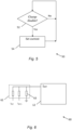
- FIG. 2 is a flow chart showing an algorithm, indicated generally by the reference numeral 20, in accordance with an example embodiment.
- the algorithm 20 may be implemented by the system 10 described above.
- the algorithm 20 starts at operation 22, where the circuit 13 is selectively decoupled from the battery 11 of the system 10. Specifically, the circuit 13 is decoupled (e.g. using the protection circuit 15) from the battery 11 in the event that the battery voltage is below a first threshold voltage level.
- a first charge control signal is generated by the circuit 13 (e.g. by the control module 17).
- the first control signal has a charge enable state and a charge disable state.
- the first control signal will be floating, such that the first control signal has neither the charge enable state nor the charge disable state.
- the battery 11 is charged (using the charging unit 12) unless the first control signal has the charge disable state.
- the first control signal has the charge enable state, or the first control signal is floating (as discussed above)
- the battery 11 may be charged in the operation 26 (provided, of course, that a suitable charging arrangement, such as the power supply 14, is provided).
- FIG. 3 is a block diagram of a system, indicated generally by the reference numeral 30, in accordance with an example embodiment.
- the system 30 includes the charging unit 12 and the control module 17 described above.
- the system 30 further comprises a resistor arrangement 32 provided between the charging unit 12 and the control module 17.
- the resistor arrangement 32 is configured to receive the first control signal (charge_en) from the control module 17 and to receive a constant current source signal from the charging unit 12 (e.g. from a TS pin of the charging unit 12, as shown in FIG. 3 ).
- the constant current source signal can be used to generate a voltage within the resistor arrangement 32 that is dependent on the first control signal (charge_en), that generated voltage being used, by the charging unit 12, to determine whether to allow charging of the battery 11 described above.
- the resistor arrangement 32 comprises: a first resistor 34 having a first terminal connected to the TS pin of the charging unit 12 (i.e. to the constant current source) and a second terminal connected to ground; and a second resistor 35 having a first terminal connected to the TS pin of the charging unit 12 (i.e. to the constant current source) and a second terminal connected to the first control signal (charge_en).
- the first resistor 34 has a resistance of 10k ⁇
- the second resistor 35 has a resistance of 330 ⁇ , (of course, these resistors could have different values in alternative embodiments).
- FIG. 4 is a flow chart showing an algorithm, indicated generally by the reference numeral 40, in accordance with an example embodiment.
- the algorithm 40 may be implemented by the system 30 described above.
- the algorithm 40 starts at operation 41, where a constant current is output by the TS terminal of the charging unit 12.
- the constant current is 50 ⁇ A.
- a voltage at the TS terminal of the charging unit 12 is determined. On the basis of the determined voltage, a determination is made regarding the state of the charge_en control signal. It should be noted that there may not be a "determination" of the state of the charge_en control signal; rather, action may occur simply based on the voltage generated across the resistor arrangement 32.
- the 50 ⁇ A current flows through the 10k ⁇ , resistor to ground, resulting in a voltage of 500mV at the TS pin of the charging unit 12. This voltage is sufficient to enable the charging unit 12, such that the battery can be charged in the event that the circuit 13 is decoupled from the battery (see operation 22 above), such that the battery can be charged (see operation 26 above).
- FIG. 5 is a flow chart showing an algorithm, indicated generally by the reference numeral 50, in accordance with an example embodiment.
- the algorithm 50 is an example implementation of the operation 26 of the algorithm 20 described above.
- the algorithm 50 starts at operation 52, where a determination is made regarding whether the state of the control signal (charge_en) received at the charging unit 12 from the control module 17 is in the charge disable state. If the control signal has the charge disable state, then the operation 52 is simply repeated; otherwise (if the control signal has the charge enable state or is floating), the algorithm moves to operation 54. As noted above, there may not be a "determination" of the state of the charge_en control signal; rather, action may occur simply based on the voltage generated across the resistor arrangement 32.
- a charging current output by the charging unit 12 to charge the battery 11 is set.
- the charging current output by the charging unit 12 to charge the battery 11 may be dependent, at least in part, on a charge current control signal I SET .
- the charging current output may be set in operation 54 to a default level in the absence of a charge current control signal (e.g. I SET ).
- the default level may be a low level (e.g. 70mA) that may be used in a default condition.
- the default level may, for example, be used if the control module 17 is decoupled from the battery 11.
- FIG. 6 is a block diagram of a circuit, indicated generally by the reference numeral 60, in accordance with an example embodiment.
- the circuit 60 comprises the charging unit 12 described above, which charging unit includes an input pin I SET .
- the voltage received at the input pin I SET may be used to determine the charging current applied in the operation 26 of the algorithm 20.
- the voltage at the input pin I SET may be dependent on the state of two control signals: I SET and I SET1 . Those control signals may be provided to a resistor arrangement 62.
- the control signals I SET and I SET1 may be provided by the control module 17, such that the control module 17 may set whether charging is enabled by setting the first control signal (charge_en) and, if charging is enabled, may set the charging level by setting the control signals I SET and I SET1 .
- the control module 17 may be decoupled from the battery 11 such that the control signals I SET and I SET1 may, in some circumstances, be floating.
- the charge current is set in the operation 26 in accordance with the following logic:
- the charge current output may be dependent, at least in part, on a temperature of the battery 11.
- a negative temperature coefficient resistor NTC may be provided as part of a battery temperature monitoring algorithm.
- FIG. 7 is a flow chart showing an algorithm, indicated generally by the reference numeral 70, in accordance with an example embodiment.
- the algorithm 70 may, for example, be implemented by the control module 17.
- the algorithm 70 starts at operation 71, where a temperature of operation is determined (e.g. measured).
- the operation 71 may determine the temperature of the battery 11.
- the operation 71 may be implemented in many ways, for example using a thermocouple or an NTC resistor.
- the system 10 it is determined whether the system 10 is being used to generate an aerosol. For example, a determination may be made regarding whether a user is activating the device (e.g. taking a puff).
- the first control signal discussed above is set to the charge disable state and the algorithm 70 terminates at operation 76. If the battery charging is enabled in the operation 73, then said first control signal is set to the charge enable state and the algorithm 70 moves to operation 74, where the current charging level is set.
- the current charging level may be set in operation 74 in a number of ways (and may be implemented by setting the control signals I SET and I SET1 , as discussed above).
- the current charging level may be dependent (at least in part) on the temperature of the battery 11.
- the current charging level may be dependent on how long the charging process has been in operation (e.g. the charging level may increase over time). Other factors could also be taken into account.
- FIG. 8 is a flow chart showing an algorithm, indicated generally by the reference numeral 80, in accordance with an example embodiment.
- the algorithm 80 starts at operation 82, where the circuit 13 (and hence the control module 17) is decoupled from the battery 11 in the event that the battery voltage is below a first threshold level (T 1 ). As discussed above, with the control circuit decoupled, it may still be possible to charge the battery, such that the battery voltage level can rise about the first threshold level. At that stage, the circuit 13 may be coupled to the battery again and normal operation resumed.
- T 1 a first threshold level
- the system 10 is disabled in the event that the battery voltage is below a second threshold (T 2 ).
- Disabling the system may involve permanently decoupling the circuit 13 from said battery 11 when the battery voltage is below the second threshold level, wherein the second threshold level is lower than the first threshold level.
- the protection module 15 may be provided with a feature that prevents the battery 11 from being charged in the event that the battery voltage drops below the first threshold, even if a charging source (such as the power supply 14) is attached.
- the algorithm 80 is shown with two separate operations, the operations 82 and 84 may, in practice, be implemented at the same time. Moreover, the operations 82 and 84 may be implemented in an ongoing fashion. In one example embodiment, the operations 82 and 84 are implemented by the protection module 15 on the basis of the battery voltage.
- FIG. 9 is a block diagram of a circuit, indicated generally by the reference numeral 90, in accordance with an example embodiment.
- the circuit 90 includes a charging management module 92.
- the module 92 is an example of the charging module 12 described above.
- the charging management module 92 includes a number of pins, some of which are described below.
- a first pin (IN) is configured to receive a voltage V BUS from a power supply (when connected).
- the power supply 14 described above may be selectively connectable to the first pin (IN).
- a second pin receives a current setting voltage.
- a resistor arrangement 93 (similar to the resistor arrangement 62 described above) converts control signals I SET and I SET1 (as output, for example, by the control circuit 17) into the current setting voltage at the second pin ISET.
- a ninth pin (TS) receives a charging control signal.
- a resistor arrangement 94 (similar to the resistor arrangement 32 described above) converts a charge_en control signal (as output, for example, by the control circuit 17) into the charging control signal.
- a tenth pin (OUT) provides a charging current to a battery (such as the battery 11 described above).
- FIG. 10 is a block diagram of a non-combustible aerosol provision device, indicated generally by the reference numeral 100, in accordance with an example embodiment.
- the device 100 is a modular device, comprising a first part 101 and a second part 102.
- the first part 101 of the device 100 includes a control circuit 103 (which may include at least some of the charging unit 12, the circuit 13, the protection module 15, the regulator 16 and the control module 17 described above) and a battery 104 (such as the battery 11 described above).
- the second part 102 of the device 100 includes a heater 105 and a liquid reservoir 106.
- the first part 101 includes a first connector 107a (such as a USB connector).
- the first connector 107a may enable connection to be made to a power source (such as the power source 14 described above) for charging the battery 104 (e.g. under the control of the control circuit 103).
- the first part 101 also includes a second connector 107b that can be removably connected to a first connector 108 of the second part 102.
- air is drawn into an air inlet of the heater 105, as indicated by the arrow 110.
- the heater is used to heat the air (e.g. under the control of the circuit 103).
- the heated air is directed to the liquid reservoir 106, where an aerosol is generated.
- the aerosol exits the device at an air outlet, as indicated by the arrow 111 (for example into the mouth of a user of the device 100).
Landscapes
- Engineering & Computer Science (AREA)
- Power Engineering (AREA)
- Charge And Discharge Circuits For Batteries Or The Like (AREA)
- Secondary Cells (AREA)
- Disintegrating Or Milling (AREA)
Claims (15)
- Vorrichtung für ein nicht brennbares Aerosol-Bereitstellungssystem, umfassend:eine Ladeeinheit (12), die konfiguriert ist, um eine Batterie (11) des Aerosol-Bereitstellungssystems zu laden;eine Schaltung (13), die ein Steuermodul (17) umfasst, wobei das Steuermodul ein erstes Steuersignal mit einem Ladefreigabezustand und einem Ladesperrzustand ausgibt;
undein Schutzmodul (15), das konfiguriert ist, um die Schaltung von der Batterie zu entkoppeln, wenn die Batteriespannung unter einem ersten Schwellenwert ist,wobei:die Ladeeinheit (12) konfiguriert ist, um die Batterie (11) zu laden, es sei denn, das erste Steuersignal weist den Ladesperrzustand auf; unddas Schutzmodul (15) konfiguriert ist, um zu verhindern, dass die Batterie geladen wird, wenn die Batteriespannung unter einem zweiten Schwellenwert ist, wobei der zweite Schwellenwert niedriger als der erste Schwellenwert ist. - Vorrichtung nach Anspruch 1, wobei die Schutzschaltung (15) konfiguriert ist, um die Schaltung (13) permanent von der Batterie zu entkoppeln, wenn die Batteriespannung unter dem zweiten Schwellenwert ist.
- Vorrichtung nach Anspruch 1 oder Anspruch 2, wobei das Steuermodul (17) konfiguriert ist, um ein Ladestromsteuersignal auszugeben.
- Vorrichtung nach Anspruch 3, wobei ein Ladestrom, der durch die Ladeeinheit (12) ausgegeben wird, um die Batterie (11) zu laden, zumindest teilweise von dem Ladestromsteuersignal abhängt und wobei die Ladestromausgabe bei Fehlen des Ladestromsteuersignals optional auf einen Standardwert eingestellt ist.
- Vorrichtung nach Anspruch 3 oder Anspruch 4, wobei das Ladestromsteuersignal zumindest teilweise von einer Temperatur der Batterie abhängig ist.
- Vorrichtung nach einem der Ansprüche 1 bis 5, wobei:das Steuermodul (17) konfiguriert ist, um das erste Steuersignal basierend zumindest teilweise auf einer bestimmten Temperatur der Batterie in den Ladefreigabezustand oder den Ladesperrzustand einzustellen; und/oderdas Steuermodul (17) konfiguriert ist, um das erste Steuersignal in den Ladesperrzustand einzustellen, wenn die Vorrichtung verwendet wird, um ein Aerosol zu erzeugen.
- Vorrichtung nach einem der Ansprüche 1 bis 6, ferner umfassend eine Widerstandsanordnung (32), wobei die Widerstandsanordnung konfiguriert ist, um das erste Steuersignal von dem Steuermodul zu empfangen und um ein Konstantstromquellensignal von der Ladeeinheit zu empfangen, wobei das Konstantstromquellensignal eine Spannung innerhalb der Widerstandsanordnung abhängig von dem ersten Steuersignal erzeugt, wobei die Spannung durch die Ladeeinheit verwendet wird, um zu bestimmen, ob Laden der Batterie zuzulassen ist, wobei die Widerstandsanordnung optional Folgendes umfasst:einen ersten Widerstand (34) mit einem ersten Anschluss, der konfiguriert ist, um das Konstantstromquellensignal zu empfangen, und einem zweiten Anschluss, der mit Masse verbunden ist; undeinen zweiten Widerstand (35) mit einem ersten Anschluss, der konfiguriert ist, um das Konstantstromquellensignal zu empfangen, und einem zweiten Anschluss, der konfiguriert ist, um das erste Steuersignal zu empfangen.
- Vorrichtung nach einem der Ansprüche 1 bis 7, ferner umfassend einen Regler (16), der konfiguriert ist, um eine Betriebsspannung zu regeln, die der Schaltung (13) bereitgestellt wird.
- Vorrichtung nach einem der Ansprüche 1 bis 8, wobei das Steuermodul (17) konfiguriert ist, um eine Aerosolerzeugungsschaltung der Vorrichtung zu steuern.
- Vorrichtung nach einem der Ansprüche 1 bis 9, ferner umfassend die Batterie.
- Nicht brennbares Aerosol-Bereitstellungssystem, umfassend eine Vorrichtung nach einem der Ansprüche 1 bis 10, wobei das Aerosol-Bereitstellungssystem optional konfiguriert ist, um einen entfernbaren Artikel zu empfangen, der ein aerosolerzeugendes Material umfasst.
- Verfahren, umfassend:Entkoppeln (22) einer Schaltung (13) von einer Batterie (11) eines nicht brennbaren Aerosol-Bereitstellungssystems in dem Fall, dass die Batteriespannung unter einem ersten Schwellenwert ist, wobei die Schaltung ein Steuermodul umfasst;Verhindern, dass die Batterie geladen wird, wenn die Batteriespannung unter einem zweiten Schwellenwert ist, wobei der zweite Schwellenwert niedriger als der erste Schwellenwert ist;Verwenden des Steuermoduls, um ein erstes Steuersignal zu erzeugen (24), wobei das erste Steuersignal einen Ladefreigabezustand und einen Ladesperrzustand aufweist; undLaden (26) der Batterie, es sei denn, das erste Steuersignal weist den Ladesperrzustand auf
- Verfahren nach Anspruch 12, wobei das Steuersignal in dem Fall, dass die Schaltung von der Batterie entkoppelt ist, weder den Ladefreigabezustand noch den Ladesperrzustand aufweist.
- Verfahren nach Anspruch 12 oder Anspruch 13, ferner umfassend permanentes Entkoppeln der Schaltung von der Batterie in dem Fall, dass die Batteriespannung unter dem zweiten Schwellenwert ist.
- Verfahren nach einem der Ansprüche 12 bis 14, ferner umfassend:Erzeugen einer Spannung innerhalb einer Widerstandsanordnung (32) abhängig von dem ersten Steuersignal; undBestimmen, ob die Batterie abhängig von der erzeugten Spannung zu laden ist.
Applications Claiming Priority (2)
| Application Number | Priority Date | Filing Date | Title |
|---|---|---|---|
| GB201915511A GB201915511D0 (en) | 2019-10-25 | 2019-10-25 | Battery charging |
| PCT/GB2020/052684 WO2021079139A1 (en) | 2019-10-25 | 2020-10-23 | Battery charging |
Publications (2)
| Publication Number | Publication Date |
|---|---|
| EP4048100A1 EP4048100A1 (de) | 2022-08-31 |
| EP4048100B1 true EP4048100B1 (de) | 2023-11-29 |
Family
ID=68768820
Family Applications (1)
| Application Number | Title | Priority Date | Filing Date |
|---|---|---|---|
| EP20799806.3A Active EP4048100B1 (de) | 2019-10-25 | 2020-10-23 | Vorrichtung für ein ein nicht brennbares aerosol erzeugungssystem |
Country Status (18)
| Country | Link |
|---|---|
| US (1) | US20220360103A1 (de) |
| EP (1) | EP4048100B1 (de) |
| JP (2) | JP7578687B2 (de) |
| KR (1) | KR102864017B1 (de) |
| CN (1) | CN114845590B (de) |
| AR (1) | AR120282A1 (de) |
| AU (1) | AU2020370825B2 (de) |
| BR (1) | BR112022007862A2 (de) |
| ES (1) | ES2969327T3 (de) |
| GB (1) | GB201915511D0 (de) |
| HU (1) | HUE065069T2 (de) |
| IL (1) | IL292402A (de) |
| LT (1) | LT4048100T (de) |
| MX (1) | MX2022004902A (de) |
| PL (1) | PL4048100T3 (de) |
| PT (1) | PT4048100T (de) |
| TW (1) | TW202135416A (de) |
| WO (1) | WO2021079139A1 (de) |
Families Citing this family (2)
| Publication number | Priority date | Publication date | Assignee | Title |
|---|---|---|---|---|
| CN116075243A (zh) * | 2020-06-10 | 2023-05-05 | 电子烟研究所公司 | 气溶胶供应设备 |
| US12520880B2 (en) | 2021-01-18 | 2026-01-13 | Altria Client Services Llc | Heat-not-burn (HNB) aerosol-generating devices including energy based heater control, and methods of controlling a heater |
Citations (13)
| Publication number | Priority date | Publication date | Assignee | Title |
|---|---|---|---|---|
| US20110265806A1 (en) | 2010-04-30 | 2011-11-03 | Ramon Alarcon | Electronic smoking device |
| WO2013093695A1 (en) | 2011-12-18 | 2013-06-27 | Sis Resources Ltd. | Charging electronic cigarette |
| CN203326671U (zh) | 2013-07-10 | 2013-12-04 | 向智勇 | 一种用于电子烟盒的控制电路 |
| CN203482903U (zh) | 2013-10-17 | 2014-03-19 | 向智勇 | 触摸式控制电路和烟盒电路 |
| CN204070537U (zh) | 2014-06-30 | 2015-01-07 | 惠州市吉瑞科技有限公司 | 一种控制电路及电子烟 |
| EP2921064A1 (de) | 2012-11-13 | 2015-09-23 | Joyetech (Changzhou) Electronics Co., Ltd. | Intelligente steuerung und verfahren für eine elektronische zigarette |
| JP2016005322A (ja) | 2014-06-16 | 2016-01-12 | 日立マクセル株式会社 | 保護回路、電池ユニット、及び電子機器 |
| WO2016016620A1 (en) | 2014-07-29 | 2016-02-04 | Nicoventures Holdings Limited | E-cigarette and re-charging pack |
| WO2016165055A1 (zh) | 2015-04-13 | 2016-10-20 | 惠州市吉瑞科技有限公司深圳分公司 | 一种雾化组件及电子烟 |
| US20170303597A1 (en) | 2015-01-26 | 2017-10-26 | Xmart Chip Microelectronic Co. Limited | Electronic Smoking Apparatus and Circuitry |
| US10004269B2 (en) | 2014-06-30 | 2018-06-26 | Huizhou Kimree Technology Co., Ltd. Shenzhen Branch | Control circuit, electronic cigarette and method for controlling electronic cigarette |
| WO2018192722A1 (en) | 2017-04-18 | 2018-10-25 | Philip Morris Products S.A. | Aerosol-generating system with overheating prevention |
| WO2019150546A1 (ja) | 2018-02-02 | 2019-08-08 | 日本たばこ産業株式会社 | 吸引成分生成装置の電源ユニット、吸引成分生成装置の電源ユニットにおける既知抵抗の電気抵抗値の選択方法 |
Family Cites Families (14)
| Publication number | Priority date | Publication date | Assignee | Title |
|---|---|---|---|---|
| EP2701268A1 (de) * | 2012-08-24 | 2014-02-26 | Philip Morris Products S.A. | Tragbares elektronisches System mit Ladevorrichtung und Verfahren zum Laden einer Sekundärbatterie |
| BR112016022630B1 (pt) * | 2014-04-30 | 2022-03-03 | Philip Morris Products S.A | Dispositivo e sistema gerador de aerossol, método para controle de um dispositivo gerador de aerossol, circuito elétrico para um dispositivo gerador de aerossol e meio de armazenamento legível por computador |
| KR101570876B1 (ko) * | 2014-10-28 | 2015-11-20 | 이충언 | 전자담배 |
| WO2016210242A1 (en) * | 2015-06-25 | 2016-12-29 | Altria Client Services Llc | Electronic vaping device having pressure sensor |
| US20170119052A1 (en) * | 2015-10-30 | 2017-05-04 | R.J. Reynolds Tobacco Company | Application specific integrated circuit (asic) for an aerosol delivery device |
| CN206060307U (zh) * | 2016-09-28 | 2017-03-29 | 上海萨能电子科技有限公司 | 一种蓄电池充放电平衡装置 |
| CN109068731B (zh) * | 2017-03-06 | 2020-02-07 | 日本烟草产业株式会社 | 电池组件、香味吸入器、控制电池组件的方法以及存储介质 |
| CN107404107B (zh) * | 2017-08-15 | 2020-02-14 | 惠州市新泓威科技有限公司 | 一种电子烟的防干烧装置及其控制方法 |
| RU2735592C1 (ru) * | 2017-10-18 | 2020-11-05 | Джапан Тобакко Инк. | Устройство, генерирующее компонент для вдыхания, способ управления устройством, генерирующим компонент для вдыхания, и компьютерно-читаемый носитель данных |
| EP3864982A1 (de) * | 2017-10-23 | 2021-08-18 | Japan Tobacco Inc. | Vorrichtung zur erzeugung eines inhalationsbestandteils |
| CN207518302U (zh) * | 2017-10-27 | 2018-06-19 | 广州极飞科技有限公司 | 储能电池控制电路和储能电池 |
| CN208241335U (zh) * | 2018-03-05 | 2018-12-14 | 常州市派腾电子技术服务有限公司 | 电池保护电路及电子烟 |
| JP6577106B2 (ja) * | 2018-09-07 | 2019-09-18 | 日本たばこ産業株式会社 | バッテリユニット |
| JP6577113B1 (ja) * | 2018-10-03 | 2019-09-18 | 日本たばこ産業株式会社 | エアロゾル生成装置、エアロゾル生成装置用の制御ユニット、方法及びプログラム |
-
2019
- 2019-10-25 GB GB201915511A patent/GB201915511D0/en not_active Ceased
-
2020
- 2020-10-06 TW TW109134618A patent/TW202135416A/zh unknown
- 2020-10-22 AR ARP200102926A patent/AR120282A1/es active IP Right Grant
- 2020-10-23 EP EP20799806.3A patent/EP4048100B1/de active Active
- 2020-10-23 LT LTEPPCT/GB2020/052684T patent/LT4048100T/lt unknown
- 2020-10-23 MX MX2022004902A patent/MX2022004902A/es unknown
- 2020-10-23 KR KR1020227017336A patent/KR102864017B1/ko active Active
- 2020-10-23 IL IL292402A patent/IL292402A/en unknown
- 2020-10-23 ES ES20799806T patent/ES2969327T3/es active Active
- 2020-10-23 AU AU2020370825A patent/AU2020370825B2/en active Active
- 2020-10-23 PT PT207998063T patent/PT4048100T/pt unknown
- 2020-10-23 CN CN202080089434.7A patent/CN114845590B/zh active Active
- 2020-10-23 BR BR112022007862A patent/BR112022007862A2/pt unknown
- 2020-10-23 HU HUE20799806A patent/HUE065069T2/hu unknown
- 2020-10-23 WO PCT/GB2020/052684 patent/WO2021079139A1/en not_active Ceased
- 2020-10-23 PL PL20799806.3T patent/PL4048100T3/pl unknown
- 2020-10-23 US US17/755,198 patent/US20220360103A1/en active Pending
- 2020-10-23 JP JP2022523870A patent/JP7578687B2/ja active Active
-
2024
- 2024-03-18 JP JP2024042437A patent/JP2024073600A/ja not_active Withdrawn
Patent Citations (13)
| Publication number | Priority date | Publication date | Assignee | Title |
|---|---|---|---|---|
| US20110265806A1 (en) | 2010-04-30 | 2011-11-03 | Ramon Alarcon | Electronic smoking device |
| WO2013093695A1 (en) | 2011-12-18 | 2013-06-27 | Sis Resources Ltd. | Charging electronic cigarette |
| EP2921064A1 (de) | 2012-11-13 | 2015-09-23 | Joyetech (Changzhou) Electronics Co., Ltd. | Intelligente steuerung und verfahren für eine elektronische zigarette |
| CN203326671U (zh) | 2013-07-10 | 2013-12-04 | 向智勇 | 一种用于电子烟盒的控制电路 |
| CN203482903U (zh) | 2013-10-17 | 2014-03-19 | 向智勇 | 触摸式控制电路和烟盒电路 |
| JP2016005322A (ja) | 2014-06-16 | 2016-01-12 | 日立マクセル株式会社 | 保護回路、電池ユニット、及び電子機器 |
| CN204070537U (zh) | 2014-06-30 | 2015-01-07 | 惠州市吉瑞科技有限公司 | 一种控制电路及电子烟 |
| US10004269B2 (en) | 2014-06-30 | 2018-06-26 | Huizhou Kimree Technology Co., Ltd. Shenzhen Branch | Control circuit, electronic cigarette and method for controlling electronic cigarette |
| WO2016016620A1 (en) | 2014-07-29 | 2016-02-04 | Nicoventures Holdings Limited | E-cigarette and re-charging pack |
| US20170303597A1 (en) | 2015-01-26 | 2017-10-26 | Xmart Chip Microelectronic Co. Limited | Electronic Smoking Apparatus and Circuitry |
| WO2016165055A1 (zh) | 2015-04-13 | 2016-10-20 | 惠州市吉瑞科技有限公司深圳分公司 | 一种雾化组件及电子烟 |
| WO2018192722A1 (en) | 2017-04-18 | 2018-10-25 | Philip Morris Products S.A. | Aerosol-generating system with overheating prevention |
| WO2019150546A1 (ja) | 2018-02-02 | 2019-08-08 | 日本たばこ産業株式会社 | 吸引成分生成装置の電源ユニット、吸引成分生成装置の電源ユニットにおける既知抵抗の電気抵抗値の選択方法 |
Non-Patent Citations (18)
| Title |
|---|
| ANONYMOUS: "1 A, Single-Input, Single Cell Li-Ion and Li-Pol Battery Charger With Auto Start", TEXAS INSTRUMENTS (BQ24040), 1 February 2013 (2013-02-01), pages 1 - 33, XP093212059 |
| ANONYMOUS: "1 A, Single-Input, Single Cell Li-Ion Battery Charger", TEXAS INSTRUMENTS, 1 February 2010 (2010-02-01), pages 1 - 31, XP093212032 |
| ANONYMOUS: "1A single-chip Li-Ion /Li-Pol charge management IC with thermal regulation (BQ2406x)", TEXAS INSTRUMENTS, 1 January 2006 (2006-01-01), pages 1 - 36, XP093212038 |
| ANONYMOUS: "A guide to the safe use of secondary lithium ion batteries in notebook-type personal computers", JAPAN ELECTRONICS AND INFORMATION TECHNOLOGY INDUSTRIES ASSOCIATION AND BATTERY ASSOCIATION OF JAPAN, 20 April 2007 (2007-04-20), pages 1 - 18, XP002558314 |
| ANONYMOUS: "Battery charging, gauging and protection", 6 November 2014 (2014-11-06), XP093212042, Retrieved from the Internet <URL:https://www.ti.com/video/3877826608001?keyMatch=Battery%20charging%20gauging%20and%20protection&tisearch=universal_search&f-videos=Video,Video%20series> [retrieved on 20241007] |
| ANONYMOUS: "Electronic cigarette", WIKIPEDIA, 16 July 2013 (2013-07-16), pages 1 - 17, XP093212049, Retrieved from the Internet <URL:https://en.wikipedia.org/w/index.php?title=Electronic_cigarette&oldid=564504423> [retrieved on 20241007] |
| ANONYMOUS: "NE57610 Li-Ion battery charger control with adjustable thresholds", DATASHEET, 5 November 2002 (2002-11-05), pages 1 - 17, XP055951681 |
| ANONYMOUS: "S8241 Battery protection IC for 1cell pack ", SEIKO INSTRUMENTS, 1 January 2013 (2013-01-01), pages 1 - 40, XP093212036 |
| ANONYMOUS: "Single-Input 1-Cell Li+ Charger with OVP Protection and programmable charge timer", MAXIM, 1 January 2009 (2009-01-01), pages 1 - 12, XP055951679 |
| ANONYMOUS: "SN2040 1 A, Single-Input, Single Cell Li-Ion and Li-Pol Battery Charger", TEXAS INSTRUMENTS, 1 July 2016 (2016-07-01), pages 1 - 34, XP093212030, Retrieved from the Internet <URL:https://file.elecfans.com/web2/M00/4E/02/poYBAGK76FSAaf7VABB49gRL5EI769.pdf> [retrieved on 20241007] |
| ANONYMOUS: "Understanding the characteristics of Li-Ion batteries and Richtek power management solutions", RICHTEK, 1 January 2014 (2014-01-01), pages 1 - 22, XP055951683 |
| GUNDERSON DAVID: "Li-Ion battery temperature trends during charge and discharge", MICRO POWER, 5 September 2012 (2012-09-05), pages 1 - 4, XP055951665 |
| JINRONG QIAN: "Li-ion battery-charger solutions for JEITA compliance", ANOLOGUE APPLICATIONS JOURNAL, TEXAS INSTRUMENTS, no. Q1, 1 October 2010 (2010-10-01), pages 8 - 11, XP055774908 |
| QIAN JINRONG: "Improving battery safety, charging, and fuel gauging in portable media applications", ANALOGUE APPLICATIONS JOURNAL, vol. 9, no. 13, 1 January 2009 (2009-01-01), pages 9 - 13, XP055903219 |
| SAXENA SAURABH; KONG LINGXI; PECHT MICHAEL G.: "Exploding E-Cigarettes: A Battery Safety Issue", IEEE ACCESS, vol. 6, 1 January 1900 (1900-01-01), USA , pages 21442 - 21466, XP011682810, DOI: 10.1109/ACCESS.2018.2821142 |
| THOMAS B. REDDY: "Linden's handbook of Batteries", 1 January 2011, MCGRAWHILL, ISBN: 978-0-07-162421-3, article DANIEL D FRIEL: "Chapter 5: Battery design", pages: 5.1 - 5.23, XP009557619 |
| YEVGEN BARSUKOV, JINRONG QIAN: "Battery power management for portable devices", 1 January 2013, ARTECH HOUSE , GB , ISBN: 978-1-60807-491-4, article ANONYMOUS: "Battery charger techniques", pages: 50 - 59, XP093212044 |
| YEVGEN BARSUKOV, JINRONG QIAN: "Battery power management for portable devices", 1 January 2013, ARTECH HOUSE, GB, ISBN: 978-1-60807-491-4, article ANONYMOUS: "Battery safety and protections ", pages: 98 - 99, XP093212046 |
Also Published As
| Publication number | Publication date |
|---|---|
| PT4048100T (pt) | 2024-01-12 |
| TW202135416A (zh) | 2021-09-16 |
| ES2969327T3 (es) | 2024-05-17 |
| EP4048100A1 (de) | 2022-08-31 |
| JP7578687B2 (ja) | 2024-11-06 |
| US20220360103A1 (en) | 2022-11-10 |
| GB201915511D0 (en) | 2019-12-11 |
| HUE065069T2 (hu) | 2024-05-28 |
| NZ787761A (en) | 2024-11-29 |
| MX2022004902A (es) | 2022-05-16 |
| JP2024073600A (ja) | 2024-05-29 |
| KR20220086657A (ko) | 2022-06-23 |
| AU2020370825A1 (en) | 2022-05-26 |
| IL292402A (en) | 2022-06-01 |
| JP2023501915A (ja) | 2023-01-20 |
| AR120282A1 (es) | 2022-02-09 |
| CA3155610A1 (en) | 2021-04-29 |
| AU2020370825B2 (en) | 2023-05-25 |
| WO2021079139A1 (en) | 2021-04-29 |
| KR102864017B1 (ko) | 2025-09-23 |
| BR112022007862A2 (pt) | 2022-07-12 |
| LT4048100T (lt) | 2024-01-10 |
| CN114845590A (zh) | 2022-08-02 |
| PL4048100T3 (pl) | 2024-03-18 |
| CN114845590B (zh) | 2025-11-14 |
Similar Documents
| Publication | Publication Date | Title |
|---|---|---|
| AU2021256843B2 (en) | Aerosol provision device and method | |
| JP7701382B2 (ja) | エアロゾル供給デバイス | |
| JP2024073600A (ja) | バッテリーの充電 | |
| US20230232910A1 (en) | Aerosol provision device | |
| JP7505152B2 (ja) | エアロゾル供給デバイス | |
| CA3155610C (en) | Battery charging | |
| CA3173384C (en) | Aerosol provision device | |
| CA3173529C (en) | Aerosol provision device and method |
Legal Events
| Date | Code | Title | Description |
|---|---|---|---|
| STAA | Information on the status of an ep patent application or granted ep patent |
Free format text: STATUS: UNKNOWN |
|
| STAA | Information on the status of an ep patent application or granted ep patent |
Free format text: STATUS: THE INTERNATIONAL PUBLICATION HAS BEEN MADE |
|
| PUAI | Public reference made under article 153(3) epc to a published international application that has entered the european phase |
Free format text: ORIGINAL CODE: 0009012 |
|
| STAA | Information on the status of an ep patent application or granted ep patent |
Free format text: STATUS: REQUEST FOR EXAMINATION WAS MADE |
|
| 17P | Request for examination filed |
Effective date: 20220523 |
|
| AK | Designated contracting states |
Kind code of ref document: A1 Designated state(s): AL AT BE BG CH CY CZ DE DK EE ES FI FR GB GR HR HU IE IS IT LI LT LU LV MC MK MT NL NO PL PT RO RS SE SI SK SM TR |
|
| DAV | Request for validation of the european patent (deleted) | ||
| DAX | Request for extension of the european patent (deleted) | ||
| GRAP | Despatch of communication of intention to grant a patent |
Free format text: ORIGINAL CODE: EPIDOSNIGR1 |
|
| STAA | Information on the status of an ep patent application or granted ep patent |
Free format text: STATUS: GRANT OF PATENT IS INTENDED |
|
| P01 | Opt-out of the competence of the unified patent court (upc) registered |
Effective date: 20230505 |
|
| INTG | Intention to grant announced |
Effective date: 20230602 |
|
| P02 | Opt-out of the competence of the unified patent court (upc) changed |
Effective date: 20230604 |
|
| GRAS | Grant fee paid |
Free format text: ORIGINAL CODE: EPIDOSNIGR3 |
|
| GRAA | (expected) grant |
Free format text: ORIGINAL CODE: 0009210 |
|
| STAA | Information on the status of an ep patent application or granted ep patent |
Free format text: STATUS: THE PATENT HAS BEEN GRANTED |
|
| AK | Designated contracting states |
Kind code of ref document: B1 Designated state(s): AL AT BE BG CH CY CZ DE DK EE ES FI FR GB GR HR HU IE IS IT LI LT LU LV MC MK MT NL NO PL PT RO RS SE SI SK SM TR |
|
| REG | Reference to a national code |
Ref country code: GB Ref legal event code: FG4D |
|
| REG | Reference to a national code |
Ref country code: CH Ref legal event code: EP |
|
| REG | Reference to a national code |
Ref country code: DE Ref legal event code: R096 Ref document number: 602020022031 Country of ref document: DE |
|
| REG | Reference to a national code |
Ref country code: IE Ref legal event code: FG4D |
|
| REG | Reference to a national code |
Ref country code: RO Ref legal event code: EPE |
|
| REG | Reference to a national code |
Ref country code: PT Ref legal event code: SC4A Ref document number: 4048100 Country of ref document: PT Date of ref document: 20240112 Kind code of ref document: T Free format text: AVAILABILITY OF NATIONAL TRANSLATION Effective date: 20240103 |
|
| REG | Reference to a national code |
Ref country code: GR Ref legal event code: EP Ref document number: 20230402577 Country of ref document: GR Effective date: 20240209 Ref country code: SK Ref legal event code: T3 Ref document number: E 43181 Country of ref document: SK |
|
| REG | Reference to a national code |
Ref country code: NL Ref legal event code: MP Effective date: 20231129 |
|
| PG25 | Lapsed in a contracting state [announced via postgrant information from national office to epo] |
Ref country code: IS Free format text: LAPSE BECAUSE OF FAILURE TO SUBMIT A TRANSLATION OF THE DESCRIPTION OR TO PAY THE FEE WITHIN THE PRESCRIBED TIME-LIMIT Effective date: 20240329 |
|
| PG25 | Lapsed in a contracting state [announced via postgrant information from national office to epo] |
Ref country code: IS Free format text: LAPSE BECAUSE OF FAILURE TO SUBMIT A TRANSLATION OF THE DESCRIPTION OR TO PAY THE FEE WITHIN THE PRESCRIBED TIME-LIMIT Effective date: 20240329 Ref country code: BG Free format text: LAPSE BECAUSE OF FAILURE TO SUBMIT A TRANSLATION OF THE DESCRIPTION OR TO PAY THE FEE WITHIN THE PRESCRIBED TIME-LIMIT Effective date: 20240229 |
|
| REG | Reference to a national code |
Ref country code: AT Ref legal event code: MK05 Ref document number: 1635158 Country of ref document: AT Kind code of ref document: T Effective date: 20231129 |
|
| REG | Reference to a national code |
Ref country code: ES Ref legal event code: FG2A Ref document number: 2969327 Country of ref document: ES Kind code of ref document: T3 Effective date: 20240517 |
|
| PG25 | Lapsed in a contracting state [announced via postgrant information from national office to epo] |
Ref country code: NL Free format text: LAPSE BECAUSE OF FAILURE TO SUBMIT A TRANSLATION OF THE DESCRIPTION OR TO PAY THE FEE WITHIN THE PRESCRIBED TIME-LIMIT Effective date: 20231129 |
|
| REG | Reference to a national code |
Ref country code: HU Ref legal event code: AG4A Ref document number: E065069 Country of ref document: HU |
|
| PG25 | Lapsed in a contracting state [announced via postgrant information from national office to epo] |
Ref country code: SE Free format text: LAPSE BECAUSE OF FAILURE TO SUBMIT A TRANSLATION OF THE DESCRIPTION OR TO PAY THE FEE WITHIN THE PRESCRIBED TIME-LIMIT Effective date: 20231129 Ref country code: RS Free format text: LAPSE BECAUSE OF FAILURE TO SUBMIT A TRANSLATION OF THE DESCRIPTION OR TO PAY THE FEE WITHIN THE PRESCRIBED TIME-LIMIT Effective date: 20231129 Ref country code: NO Free format text: LAPSE BECAUSE OF FAILURE TO SUBMIT A TRANSLATION OF THE DESCRIPTION OR TO PAY THE FEE WITHIN THE PRESCRIBED TIME-LIMIT Effective date: 20240229 Ref country code: NL Free format text: LAPSE BECAUSE OF FAILURE TO SUBMIT A TRANSLATION OF THE DESCRIPTION OR TO PAY THE FEE WITHIN THE PRESCRIBED TIME-LIMIT Effective date: 20231129 Ref country code: LV Free format text: LAPSE BECAUSE OF FAILURE TO SUBMIT A TRANSLATION OF THE DESCRIPTION OR TO PAY THE FEE WITHIN THE PRESCRIBED TIME-LIMIT Effective date: 20231129 Ref country code: HR Free format text: LAPSE BECAUSE OF FAILURE TO SUBMIT A TRANSLATION OF THE DESCRIPTION OR TO PAY THE FEE WITHIN THE PRESCRIBED TIME-LIMIT Effective date: 20231129 |
|
| PG25 | Lapsed in a contracting state [announced via postgrant information from national office to epo] |
Ref country code: DK Free format text: LAPSE BECAUSE OF FAILURE TO SUBMIT A TRANSLATION OF THE DESCRIPTION OR TO PAY THE FEE WITHIN THE PRESCRIBED TIME-LIMIT Effective date: 20231129 |
|
| PG25 | Lapsed in a contracting state [announced via postgrant information from national office to epo] |
Ref country code: AT Free format text: LAPSE BECAUSE OF FAILURE TO SUBMIT A TRANSLATION OF THE DESCRIPTION OR TO PAY THE FEE WITHIN THE PRESCRIBED TIME-LIMIT Effective date: 20231129 |
|
| PG25 | Lapsed in a contracting state [announced via postgrant information from national office to epo] |
Ref country code: SM Free format text: LAPSE BECAUSE OF FAILURE TO SUBMIT A TRANSLATION OF THE DESCRIPTION OR TO PAY THE FEE WITHIN THE PRESCRIBED TIME-LIMIT Effective date: 20231129 Ref country code: EE Free format text: LAPSE BECAUSE OF FAILURE TO SUBMIT A TRANSLATION OF THE DESCRIPTION OR TO PAY THE FEE WITHIN THE PRESCRIBED TIME-LIMIT Effective date: 20231129 Ref country code: DK Free format text: LAPSE BECAUSE OF FAILURE TO SUBMIT A TRANSLATION OF THE DESCRIPTION OR TO PAY THE FEE WITHIN THE PRESCRIBED TIME-LIMIT Effective date: 20231129 Ref country code: AT Free format text: LAPSE BECAUSE OF FAILURE TO SUBMIT A TRANSLATION OF THE DESCRIPTION OR TO PAY THE FEE WITHIN THE PRESCRIBED TIME-LIMIT Effective date: 20231129 |
|
| REG | Reference to a national code |
Ref country code: DE Ref legal event code: R026 Ref document number: 602020022031 Country of ref document: DE |
|
| PLBI | Opposition filed |
Free format text: ORIGINAL CODE: 0009260 |
|
| PLAX | Notice of opposition and request to file observation + time limit sent |
Free format text: ORIGINAL CODE: EPIDOSNOBS2 |
|
| 26 | Opposition filed |
Opponent name: PHILIP MORRIS PRODUCTS S.A. Effective date: 20240829 |
|
| PG25 | Lapsed in a contracting state [announced via postgrant information from national office to epo] |
Ref country code: SI Free format text: LAPSE BECAUSE OF FAILURE TO SUBMIT A TRANSLATION OF THE DESCRIPTION OR TO PAY THE FEE WITHIN THE PRESCRIBED TIME-LIMIT Effective date: 20231129 |
|
| PG25 | Lapsed in a contracting state [announced via postgrant information from national office to epo] |
Ref country code: SI Free format text: LAPSE BECAUSE OF FAILURE TO SUBMIT A TRANSLATION OF THE DESCRIPTION OR TO PAY THE FEE WITHIN THE PRESCRIBED TIME-LIMIT Effective date: 20231129 |
|
| PLBB | Reply of patent proprietor to notice(s) of opposition received |
Free format text: ORIGINAL CODE: EPIDOSNOBS3 |
|
| RAP4 | Party data changed (patent owner data changed or rights of a patent transferred) |
Owner name: NICOVENTURES TRADING LIMITED |
|
| PG25 | Lapsed in a contracting state [announced via postgrant information from national office to epo] |
Ref country code: MC Free format text: LAPSE BECAUSE OF FAILURE TO SUBMIT A TRANSLATION OF THE DESCRIPTION OR TO PAY THE FEE WITHIN THE PRESCRIBED TIME-LIMIT Effective date: 20231129 |
|
| PG25 | Lapsed in a contracting state [announced via postgrant information from national office to epo] |
Ref country code: BE Free format text: LAPSE BECAUSE OF NON-PAYMENT OF DUE FEES Effective date: 20241031 Ref country code: LU Free format text: LAPSE BECAUSE OF NON-PAYMENT OF DUE FEES Effective date: 20241023 |
|
| REG | Reference to a national code |
Ref country code: BE Ref legal event code: MM Effective date: 20241031 |
|
| PG25 | Lapsed in a contracting state [announced via postgrant information from national office to epo] |
Ref country code: FI Free format text: LAPSE BECAUSE OF FAILURE TO SUBMIT A TRANSLATION OF THE DESCRIPTION OR TO PAY THE FEE WITHIN THE PRESCRIBED TIME-LIMIT Effective date: 20231129 |
|
| PGFP | Annual fee paid to national office [announced via postgrant information from national office to epo] |
Ref country code: PL Payment date: 20250922 Year of fee payment: 6 |
|
| PG25 | Lapsed in a contracting state [announced via postgrant information from national office to epo] |
Ref country code: IE Free format text: LAPSE BECAUSE OF NON-PAYMENT OF DUE FEES Effective date: 20241023 |
|
| REG | Reference to a national code |
Ref country code: CH Ref legal event code: U11 Free format text: ST27 STATUS EVENT CODE: U-0-0-U10-U11 (AS PROVIDED BY THE NATIONAL OFFICE) Effective date: 20251101 |
|
| PGFP | Annual fee paid to national office [announced via postgrant information from national office to epo] |
Ref country code: HU Payment date: 20251027 Year of fee payment: 6 |
|
| PGFP | Annual fee paid to national office [announced via postgrant information from national office to epo] |
Ref country code: PT Payment date: 20251009 Year of fee payment: 6 |
|
| RDAF | Communication despatched that patent is revoked |
Free format text: ORIGINAL CODE: EPIDOSNREV1 |
|
| PGFP | Annual fee paid to national office [announced via postgrant information from national office to epo] |
Ref country code: DE Payment date: 20251021 Year of fee payment: 6 |
|
| PGFP | Annual fee paid to national office [announced via postgrant information from national office to epo] |
Ref country code: LT Payment date: 20250929 Year of fee payment: 6 Ref country code: GB Payment date: 20251022 Year of fee payment: 6 |
|
| PGFP | Annual fee paid to national office [announced via postgrant information from national office to epo] |
Ref country code: IT Payment date: 20251021 Year of fee payment: 6 |
|
| PGFP | Annual fee paid to national office [announced via postgrant information from national office to epo] |
Ref country code: FR Payment date: 20251030 Year of fee payment: 6 |
|
| PGFP | Annual fee paid to national office [announced via postgrant information from national office to epo] |
Ref country code: TR Payment date: 20251014 Year of fee payment: 6 Ref country code: GR Payment date: 20251022 Year of fee payment: 6 |
|
| PGFP | Annual fee paid to national office [announced via postgrant information from national office to epo] |
Ref country code: CH Payment date: 20251101 Year of fee payment: 6 |
|
| PGFP | Annual fee paid to national office [announced via postgrant information from national office to epo] |
Ref country code: CZ Payment date: 20251015 Year of fee payment: 6 |
|
| PGFP | Annual fee paid to national office [announced via postgrant information from national office to epo] |
Ref country code: RO Payment date: 20251013 Year of fee payment: 6 Ref country code: SK Payment date: 20251009 Year of fee payment: 6 |
|
| PG25 | Lapsed in a contracting state [announced via postgrant information from national office to epo] |
Ref country code: CY Free format text: LAPSE BECAUSE OF FAILURE TO SUBMIT A TRANSLATION OF THE DESCRIPTION OR TO PAY THE FEE WITHIN THE PRESCRIBED TIME-LIMIT; INVALID AB INITIO Effective date: 20201023 |
|
| PGFP | Annual fee paid to national office [announced via postgrant information from national office to epo] |
Ref country code: ES Payment date: 20251216 Year of fee payment: 6 |
|
| APAJ | Date of receipt of notice of appeal modified |
Free format text: ORIGINAL CODE: EPIDOSCNOA2O |
|
| APAW | Appeal reference deleted |
Free format text: ORIGINAL CODE: EPIDOSDREFNO |
|
| APAY | Date of receipt of notice of appeal deleted |
Free format text: ORIGINAL CODE: EPIDOSDNOA2O |
|
| APBP | Date of receipt of notice of appeal recorded |
Free format text: ORIGINAL CODE: EPIDOSNNOA2O |
|
| APAH | Appeal reference modified |
Free format text: ORIGINAL CODE: EPIDOSCREFNO |
|
| APAW | Appeal reference deleted |
Free format text: ORIGINAL CODE: EPIDOSDREFNO |
|
| APBU | Appeal procedure closed |
Free format text: ORIGINAL CODE: EPIDOSNNOA9O |
|
| RDAG | Patent revoked |
Free format text: ORIGINAL CODE: 0009271 |
|
| STAA | Information on the status of an ep patent application or granted ep patent |
Free format text: STATUS: PATENT REVOKED |