EP4048574B1 - Dispositif d'évaluation conçu pour réaliser une évaluation tolérante aux erreurs de signaux de détection pour un appareil de commande de moteur d'une direction de véhicule automobile et direction de véhicule automobile - Google Patents
Dispositif d'évaluation conçu pour réaliser une évaluation tolérante aux erreurs de signaux de détection pour un appareil de commande de moteur d'une direction de véhicule automobile et direction de véhicule automobile Download PDFInfo
- Publication number
- EP4048574B1 EP4048574B1 EP20793642.8A EP20793642A EP4048574B1 EP 4048574 B1 EP4048574 B1 EP 4048574B1 EP 20793642 A EP20793642 A EP 20793642A EP 4048574 B1 EP4048574 B1 EP 4048574B1
- Authority
- EP
- European Patent Office
- Prior art keywords
- control unit
- signal
- inputs
- signals
- sensor signals
- Prior art date
- Legal status (The legal status is an assumption and is not a legal conclusion. Google has not performed a legal analysis and makes no representation as to the accuracy of the status listed.)
- Active
Links
Images
Classifications
-
- B—PERFORMING OPERATIONS; TRANSPORTING
- B62—LAND VEHICLES FOR TRAVELLING OTHERWISE THAN ON RAILS
- B62D—MOTOR VEHICLES; TRAILERS
- B62D5/00—Power-assisted or power-driven steering
- B62D5/001—Mechanical components or aspects of steer-by-wire systems, not otherwise provided for in this maingroup
-
- G—PHYSICS
- G01—MEASURING; TESTING
- G01D—MEASURING NOT SPECIALLY ADAPTED FOR A SPECIFIC VARIABLE; ARRANGEMENTS FOR MEASURING TWO OR MORE VARIABLES NOT COVERED IN A SINGLE OTHER SUBCLASS; TARIFF METERING APPARATUS; MEASURING OR TESTING NOT OTHERWISE PROVIDED FOR
- G01D3/00—Indicating or recording apparatus with provision for the special purposes referred to in the subgroups
- G01D3/08—Indicating or recording apparatus with provision for the special purposes referred to in the subgroups with provision for safeguarding the apparatus, e.g. against abnormal operation, against breakdown
-
- B—PERFORMING OPERATIONS; TRANSPORTING
- B62—LAND VEHICLES FOR TRAVELLING OTHERWISE THAN ON RAILS
- B62D—MOTOR VEHICLES; TRAILERS
- B62D5/00—Power-assisted or power-driven steering
- B62D5/001—Mechanical components or aspects of steer-by-wire systems, not otherwise provided for in this maingroup
- B62D5/003—Backup systems, e.g. for manual steering
-
- B—PERFORMING OPERATIONS; TRANSPORTING
- B62—LAND VEHICLES FOR TRAVELLING OTHERWISE THAN ON RAILS
- B62D—MOTOR VEHICLES; TRAILERS
- B62D5/00—Power-assisted or power-driven steering
- B62D5/04—Power-assisted or power-driven steering electrical, e.g. using an electric servo-motor connected to, or forming part of, the steering gear
- B62D5/0457—Power-assisted or power-driven steering electrical, e.g. using an electric servo-motor connected to, or forming part of, the steering gear characterised by control features of the drive means as such
- B62D5/0481—Power-assisted or power-driven steering electrical, e.g. using an electric servo-motor connected to, or forming part of, the steering gear characterised by control features of the drive means as such monitoring the steering system, e.g. failures
- B62D5/049—Power-assisted or power-driven steering electrical, e.g. using an electric servo-motor connected to, or forming part of, the steering gear characterised by control features of the drive means as such monitoring the steering system, e.g. failures detecting sensor failures
Definitions
- the invention relates to an evaluation device for the fault-tolerant evaluation of at least four redundant sensor signals for an engine control unit of a motor vehicle steering system according to the preamble of claim 1, as well as a motor vehicle steering system according to the preamble of claim 11.
- Motor vehicle steering systems are safety-critical systems on whose operational and failure safety the physical integrity of the vehicle occupants directly depends. A sudden failure of the steering or unexpected steering behavior can lead to accidents with serious consequences for the vehicle occupants. For these reasons, high demands must be placed on the safety of the installed components. This applies in particular to motor vehicle steering systems that are designed as steer-by-wire steering systems.
- the position of the steered wheels is set by an electronically controlled steering actuator in order to guide the vehicle on the desired path.
- a steering angle sensor connected to the steering shaft provides a target position signal that represents the driver's steering intention.
- the steering actuator is then controlled by a position controller with sufficient power and bandwidth with a torque request signal so that the steered wheels are adjusted to the target position.
- the driver no longer has a mechanical fallback level available to keep the vehicle on the desired path.
- the components and sensors used must therefore be designed to be fault-tolerant, so that that malfunctions of individual components are noticed, but safe continued operation is still possible.
- ASIL A to D Automotive Safety Integrity Level
- US 2019/0039643 A1 describes a sensor device having a plurality of sensor units, each of which includes a plurality of sensor elements and a signal processing unit that generates and transmits an output signal that includes a plurality of detection signals corresponding to detection values of the sensor elements.
- the sensor device further includes a plurality of control units. The control units mutually send and receive the detection signals as their own sensor signals from the respective sensor unit and the detection signals as other sensor signals received from another of the control units.
- EP 0 525 574 A2 describes a system for controlling safety-relevant systems using signals that are generated in at least two computer units or computer channels. Each computer unit or each computer channel is monitored by a monitoring device. Actuators are only controlled if the associated monitoring device determines that the computer unit or the computer channel is functioning correctly.
- US 7 254 470 B2 A method and a device for generating a fault-tolerant sensor signal for an engine control device in a vehicle steering system is known. At least three sensor signals are received that characterize the parameter to be monitored, a plurality of parameter pair signals are generated from them, and one of the parameter pair signals is selected in order to generate a measured parameter signal. According to US 7 254 470 B2 It is intended that the sensor signals meet different known characteristics and therefore have a known relationship to each other when fully functional. Diagnostic signals can be generated using generated pair signals that indicate the error in the event of a fault. The disadvantage is that the known device can tolerate a maximum of one error with three sensor signals.
- This creates an evaluation device for the fault-tolerant evaluation of at least four redundant sensor signals for an engine control unit of a motor vehicle steering system which comprises two control units that are designed to be redundant to one another.
- the control units each have at least two inputs for receiving one of the redundant sensor signals, an output for the output of an output signal and a communication interface that is connected to the communication interface of the other control unit for the transmission and reception of one exchange signal each, as well as a logic circuit.
- the respective logic circuit is designed to select the output and exchange signals from these signals depending on pair comparisons between the signals received at the inputs and at the communication interface and to switch them through to the output and accordingly to the communication interface by means of selection circuits.
- an evaluation device that ensures redundant evaluation of the sensor signals, based on two preferably symmetrical, fail-safe control units that are in mutual communication with each other.
- Each control unit provides a data evaluation channel that determines an output signal based on at least two input signals and an exchange signal.
- the engine control unit is thus able to use the output signals issued to determine the functionality of the evaluation device.
- An evaluation device with this structure enables ASIL D compatible evaluation of redundant sensor signals while simultaneously requiring minimal installation space and components.
- the redundant sensor signals can be designed identically for functional sensors. However, in order to achieve diverse redundancy, the sensor signals can also be designed differently and, for example, be based on different measuring principles, but represent the same physical measured value.
- a conversion unit can be provided in the logic circuits that is suitable for converting the sensor signals to a common format for the pair comparisons and the output.
- the sensor signals originate from torque and/or angle of rotation sensors which are provided for recording the steering state of a steering handle which can be operated by the driver of the motor vehicle.
- the vehicle steering system can, for example, be designed as a vehicle power steering system or as a steer-by-wire steering system.
- the logic circuits are designed to select one of the sensor signals received at the inputs of the respective control unit as the output signal, which has been confirmed by at least one pair comparison.
- This design of the evaluation device is based on the assumption that the sensor signals transmitted directly to the inputs are more reliably error-free than the exchange signal transmitted by the other control unit, which can be impaired, for example, by transmission errors or an error in the other control unit.
- the exchange signal is therefore only used to identify the correct input signal if the sensor signals present at the inputs of the respective control unit differ from one another.
- the logic circuits are designed to output a first error signal at the output of the respective control unit when only negative pair comparisons are present.
- the downstream engine control unit can be signaled that there is an error in the respective data processing channel.
- the error signal can also be a constant level, for example a zero signal.
- the error signal can also be used to pass on diagnostic information to the engine control unit.
- the logic circuits are designed to select one of the sensor signals received at the inputs of the respective control unit as an exchange signal that was confirmed in a pair comparison with a sensor signal received at another input of the control unit or as the only one of the sensor signals received at the inputs of the control unit in a pair comparison with the exchange signal received via the communication interface.
- This design ensures that an exchange signal is only output to the communication interface if one of the signals received at the inputs has proven to be reliable in at least one pair comparison. Matches between the signals received at the inputs are given greater weight to the extent that the received exchange signal cannot cast doubt on them. If there is a match between an input signal and the received exchange signal, it must also be checked that the exchange signal does not also match another input signal whose pair comparison with the first input signal is negative.
- the logic circuits are designed to output a second error signal at the communication interface of the respective control unit if there are only negative pair comparisons between the sensor signals received at the inputs of the respective control unit and none or more of the sensor signals received at the inputs of the respective control unit were confirmed in the pair comparison with the exchange signal received at the respective communication interface.
- the output of the second error signal is therefore advantageous in the case when none of the input signals can be confirmed in terms of its reliability and therefore does not qualify as an exchange signal.
- the error signal can be used to inform the second control unit that there is an error in the sensors and/or the control unit. If the second error signal differs from a zero signal, the other control unit can clearly identify whether there is an error in the control unit or in the data transmission between the control units.
- error detection units are arranged at the inputs and the communication interface, which are designed to block the reception of faulty signals at the inputs and the communication interface.
- the error detection units are provided to check the incoming signals for plausibility. For example, it can be checked whether the signals have a predetermined format. In this way, faulty signals can be sorted out before processing. Faulty signals are therefore not received and Pair comparisons that are normally carried out with these signals are not carried out, so that such pair comparisons are not available for evaluation. By discarding faulty signals, the data processing in the evaluation device is relieved and safety is increased, as systematic disturbances that lead to identical but faulty signals are detected at an early stage.
- the logic circuits are designed to select the error-free sensor signal as the output signal in the event that only a single error-free sensor signal is present at an input of the respective control unit and the reception of the remaining signals at the remaining inputs and the communication interface is blocked by the error detection units. In this way, unchecked operability of the evaluation device is ensured even in the event that there are several errors in the input signals and the exchange signal.
- the logic circuits are designed to output a third error signal at the output if the reception of sensor signals at all inputs of the control unit is blocked by the error detection units.
- the first, second and third error signals can be the same or different. All three error signals can also be a zero signal independently of the others.
- the evaluation device is designed to evaluate exactly four redundant sensor signals and the control units each have exactly two inputs for each of the redundant sensor signals.
- Four sensors form the minimum number of sensors required to implement the inventive design of the evaluation device and to meet the ASIL D standard. To optimize installation space and costs, a design with this minimum number of sensors is preferred.
- control units preferably comprise comparator circuits.
- the logic circuits are designed to first evaluate pair comparisons between the sensor signals received at the respective inputs and to only take into account the exchange signal received from the other control unit if none of the received sensor signals is in a Pair comparison was confirmed.
- This design speeds up data processing in the evaluation device. If error-free, matching sensor signals are present at the inputs of the respective control unit, fewer pair comparisons need to be carried out and there is no time delay due to the data transfer between the control units.
- a motor vehicle steering system comprising at least four redundant sensors for detecting steering parameters and at least one electric motor with a motor control system for providing a steering force for steered wheels that is dependent on the steering parameters
- the motor vehicle steering system further comprises an evaluation device according to the invention as described above, the inputs of which are connected to the sensors and the outputs of which are connected to the motor control system.
- the sensors for detecting steering parameters can be, for example, steering angle sensors, steering torque sensors, rotor position sensors of the electric motor or vehicle speed sensors.
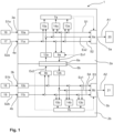
- FIG. 1 The structure of an evaluation device 1 according to the invention is shown schematically.
- the evaluation device 1 is provided for the fault-tolerant evaluation of at least four redundant sensor signals S1a, S2a, S1b, S2b for an engine control unit of a motor vehicle steering system.
- the evaluation device 1 comprises two control units 2a, 2b which are designed redundantly to one another and which each have at least two inputs 3a, 4a; 3b, 4b for receiving one of the redundant sensor signals S1a, S2a, S1b, S2b.
- the Sensor signals S1a, S2a, S1b, S2b are provided by redundant sensors 16, 17, 18, 19 which are connected to the inputs 3a, 4a; 3b, 4b.
- the control units 2a, 2b furthermore each comprise an output 5a, 5b for the output of an output signal A1, A2 and a communication interface 6a, 6b which is connected to the communication interface 6b, 6a of the other control unit 2b, 2a for the transmission and reception of an exchange signal Ex1, Ex2.
- control units 2a, 2b each have a logic circuit 7a, 7b which is designed to determine the exchange signal Ex1, Ex2 depending on pair comparisons between the signals S1a, S2a, Ex2; S1b, S2b, Ex1 to select the output signal A1, A2 and the exchange signal Ex1, Ex2 from these signals S1a, S2a, Ex2; S1b, S2b, Ex1 and to connect them to the output 5a, 5b and accordingly to the communication interface 6a, 6b by means of selection circuits 8a, 9a; 8b, 9b of the evaluation device 1.
- the evaluation device 1 shown can be part of a motor vehicle steering system, which comprises the four redundant sensors 16, 17, 18, 19 for detecting steering parameters and at least one electric motor with a motor control for providing a steering force for steered wheels that is dependent on the steering parameters.
- the sensors 16, 17, 18, 19 for detecting steering parameters can be, for example, steering angle sensors, steering torque sensors, rotor position sensors of the electric motor or motor vehicle speed sensors.
- the motor vehicle steering system further comprises the evaluation device 1, whose inputs 3a, 4a, 3b, 4b are connected to the sensors 16, 17, 18, 19 and whose outputs 5a, 5b are connected to the motor control.
- the blocks 20, 21 in Fig. 1 represent useful applications for the evaluated sensor signals within the engine control system.
- the evaluation device 1 is designed to evaluate exactly four redundant sensor signals S1a, S2a, S1b, S2b and the control units 2a, 2b each have exactly two inputs 3a, 4a; 3b, 4b for each of the redundant sensor signals S1a, S2a, S1b, S2b.
- the control units have more than two inputs for redundant sensor signals.
- the control units can have the same number or a different number of inputs.
- control units 2a, 2b comprise comparator circuits 13a, 14a, 15a; 13b, 14b, 15b for carrying out the pair comparisons.
- the comparator circuits 13a, 14a, 15a; 13b, 14b, 15b can be integrated into the logic circuits 7a, 7b or formed separately therefrom.
- the logic circuits 7a, 7b are designed to select one of the sensor signals S1a, S2a, S1b, S2b received at the inputs 3a, 4a; 3b, 4b of the respective control unit 2a, 2b as the output signal A1, A2, which has been confirmed by at least one pair comparison.
- the logic circuits 7a, 7b output a first error signal F1 at the output 5a, 5b of the respective control unit 2a, 2b if only negative pair comparisons are present.
- the columns “comparator circuit” and “exchange signal” also show that the logic circuits 7a, 7b are designed to select one of the sensor signals S1a, S2a; S1b, S2b received at the inputs 3a, 4a; 3b, 4b of the respective control unit 2a, 2b as exchange signal Ex1; Ex2, which was confirmed in a pair comparison with a sensor signal S2a, S1a; S2b, S1b received at another input 4a, 3a; 4b, 3b of the control unit or as the only one of the sensor signals S1a, S2a; S1b, S2b received at the inputs 3a, 4a; 3b, 4b of the control unit 2a, 2b in a pair comparison with the exchange signal Ex2, Ex1 received via the communication interface 6a, 6b.
- the logic circuits 7a, 7b output a second error signal F2 at the communication interface 6a, 6b of the respective control unit 2a, 2b if there are only negative pair comparisons between the sensor signals S1a, S2a; S1b, S2b received at the inputs 3a, 4a; 3b, 4b of the respective control unit 2a, 2b and none or more of the sensor signals S1a, S2a; S1b, S2b received at the inputs 3a, 4a; 3b, 4b of the respective control unit 2a, 2b were confirmed in the pair comparison with the exchange signal Ex2, Ex1 received at the respective communication interface 6a, 6b.
- error detection units 10a, 11a, 12a; 10b, 11b, 12b can be arranged at the inputs 3a, 4a; 3b, 4b and the communication interface 6a, 6b, which are designed to block the reception of erroneous signals S1a, S2a, Ex2; S1b, S2b, Ex1 at the inputs 3a, 4a; 3b, 4b and the communication interface 6a, 6b.
- the functionality of the error detection units 10a, 11a, 12a; 10b, 11b, 12b in conjunction with the comparator circuits 13a, 14a, 15a; 13b, 14b, 15b can also be found in the function table in the appendix to the description. If no error detection units 10a, 11a, 12a; 10b, 11b, 12b are provided, the function of the logic circuits 7a, 7b corresponds to the first 8 lines of Table 1. If individual error detection units 10a, 11a, 12a; 10b, 11b, 12b are provided, the function is obtained by omitting those lines that provide for a blocking ("nok") signal in a signal path without an error detection unit.
- the logic circuits 7a, 7b are designed to select the error-free sensor signal S1a, S2a; S1b, S2b as the output signal A1, A2 in the case (case no. 13 and 16) that only a single error-free sensor signal S1a, S2a; S1b, S2b is present at an input 3a, 4a; 3b, 4b of the respective control unit 2a, 2b and the reception of the remaining signals S1a, S2a, Ex2; S1b, S2b, Ex1 at the remaining inputs 3a, 4a; 3b, 4b and the communication interface 6a, 6b is blocked by the error detection units 10a, 11a, 12a; 10b, 11b, 12b.
- This signal is unchecked and is therefore referred to as a substitute value. In this way, the functionality of the evaluation device can be ensured even if the redundancy has been eliminated by several different errors.
- a third error signal F3 is output at the output 5a, 5b by the logic circuits 7a, 7b if the reception of sensor signals at all inputs 3a, 4a; 3b, 4b of the control unit 2a; 2b is blocked by the error detection units 10a, 11a; 10b, 11b.
- the logic circuits 7a, 7b first evaluate pair comparisons between the sensor signals S1a, S2a; S1b, S2b received at the respective inputs 3a, 4a; 3b, 4b and take into account the exchange signal Ex2, Ex1 received from the other control unit 2b; 2a only if none of the received sensor signals S1a, S2a; S1b, S2b was confirmed in a pair comparison.
- the operational readiness of the evaluation device can be maintained in the vast majority of cases. Only when several errors occur that cannot be reconciled with one another can no longer be provided at the output of the respective control unit. As a rule, however, the second, independent control unit can still output a valid sensor signal in these error cases.
- the last column of Table 1 shows error hypotheses that contain the error state assumed by the respective logic circuit.
- the error state determined by the logic circuits can be output via the respective error signals F1, F2, F3 or via a separate diagnostic output of the evaluation device.
Landscapes
- Engineering & Computer Science (AREA)
- Chemical & Material Sciences (AREA)
- Combustion & Propulsion (AREA)
- Transportation (AREA)
- Mechanical Engineering (AREA)
- Physics & Mathematics (AREA)
- General Physics & Mathematics (AREA)
- Safety Devices In Control Systems (AREA)
- Steering Control In Accordance With Driving Conditions (AREA)
- Arrangements For Transmission Of Measured Signals (AREA)
Claims (12)
- Dispositif d'évaluation pour l'évaluation tolérante aux défauts d'au moins quatre signaux de capteur redondants (S1a, S2a, S1b, S2b) pour un appareil de commande de moteur d'une direction de véhicule automobile, comprenant deux unités de commande (2a, 2b) conçues de manière redondante l'une par rapport à l'autre, qui ont chacune au moins deux entrées (3a, 4a ; 3b, 4b) pour recevoir respectivement l'un des signaux de capteur redondants (S1a, S2a, S1b, S2b), une sortie (5a, 5b) pour la sortie d'un signal de sortie (A1, A2) et une interface de communication (6a, 6b) qui est reliée à l'interface de communication (6b, 6a) de l'autre unité de commande (2b, 2a) pour l'émission et la réception d'un signal d'échange (Ex1, Ex2), ainsi qu'un circuit logique (7a, 7b) qui est conçu, en fonction de comparaisons par paires entre les signaux d'échange présents sur les entrées (3a, 4a ; 3b, 4b) et à l'interface de communication (6a, 6b), pour sélectionner parmi ces signaux (S1a, S2a, Ex2 ; S1b, S2b, Ex1) le signal de sortie (A1, A2) et de l'appliquer à la sortie (5a, 5b) au moyen de circuits de sélection (8a, 9a ; 8b, 9b), caractérisé en ce que les circuits logiques (7a, 7b) sont conçus, en fonction de comparaisons par paires entre les signaux (S1a, S2a, Ex2 ; S1b, S2b, Ex1) reçus aux entrées (3a, 4a ; 3b, 4b) et à l'interface de communication (6a, 6b), pour sélectionner parmi ces signaux (S1a, S2a, Ex2 ; S1b, S2b, Ex1) le signal d'échange (Ex1, Ex2) et de le transmettre à l'interface de communication (6a, 6b) au moyen des circuits de sélection (8a, 9a ; 8b, 9b) et sont conçus pour délivrer un deuxième signal d'erreur (F2) sur l'interface de communication (6a, 6b) de l'unité de commande respective (2a, 2b) lorsque seules des comparaisons de paires négatives sont effectuées entre les signaux de capteur (S1a, S2a ; S1b, S2b) sont présents et qu'aucun ou plusieurs des signaux de capteur (S1a, S2a ; S1b, S2b) reçus aux entrées (3a, 4a ; 3b, 4b) de l'unité de commande respective (2a, 2b) n'a été confirmé dans la comparaison par paire avec le signal d'échange (Ex2, Ex1) reçu à l'interface de communication respective (6a, 6b).
- Dispositif d'évaluation selon la revendication 1, caractérisé en ce que les circuits logiques (7a, 7b) sont conçus pour sélectionner l'un des signaux de capteur (S1a, S2a, S1b, S2b) reçus sur les entrées (3a, 4a ; 3b, 4b) de l'unité de commande respective (2a, 2b) comme signal de sortie (A1, A2) qui a été confirmé par au moins une comparaison de paires.
- Dispositif d'évaluation selon la revendication 1 ou 2, caractérisé en ce que les circuits logiques (7a, 7b) sont conçus pour délivrer un premier signal d'erreur (F1) à la sortie (5a, 5b) de l'unité de commande respective (2a, 2b) lorsque seules des comparaisons de paires négatives sont présentes.
- Dispositif d'évaluation selon l'une des revendications 1 à 3, caractérisé en ce que les circuits logiques (7a, 7b) sont conçus pour sélectionner l'un des signaux de capteur (S1a, S2a ; S1b, S2b) reçus aux entrées (3a, 4a ; 3b, 4b) de l'unité de commande respective (2a, 2b) comme signal d'échange (Ex1 ; Ex2) qui a été confirmé dans une comparaison par paire avec un signal de capteur reçu à une autre entrée (4a, 3a ; 4b, 3b) de l'unité de commande (S2a, S1a ; S2b, S1b) ou a été confirmé dans une comparaison par paire comme le seul des signaux de capteur (S1a, S2a ; S1b, S2b) reçus aux entrées (3a, 4a ; 3b, 4b) de l'unité de commande (2a, 2b) avec le signal d'échange (Ex2, Ex1) reçu par l'intermédiaire de l'interface de communication (6a, 6b).
- Dispositif d'évaluation selon l'une des revendications 1 à 4, caractérisé en ce que des unités de détection d'erreurs (10a, 11a, 12a ; 10b, 11b, 12b) sont disposées aux entrées (3a, 4a ; 3b, 4b) et à l'interface de communication (6a, 6b), lesquelles unités de détection d'erreurs (10a, 11a, 12a ; 10b, 11b, 12b) sont conçues pour bloquer la réception de signaux erronés (S1a, S2a, Ex2 ; S1b, S2b, Ex1) aux entrées (3a, 4a ; 3b, 4b) et à l'interface de communication (6a, 6b).
- Dispositif d'évaluation selon la revendication 5, caractérisé en ce que les circuits logiques (7a, 7b) sont adaptés pour sélectionner le signal de capteur sans erreur (S1a, S2a ; S1b, S2b) comme signal de sortie (A1, A2), dans le cas où un seul signal de capteur (S1a, S2a ; S1b, S2b) sans erreur est présent sur une entrée (3a, 4a ; 3b, 4b) de l'unité de commande (2a, 2b) respective et où la réception des autres signaux (S1a, S2a, Ex2 ; S1b, S2b, Ex1) aux autres entrées (3a, 4a ; 3b, 4b) et à l'interface de communication (6a, 6b) est bloquée par les unités de détection d'erreur (10a, 11a, 12a ; 10b, 11b, 12b),.
- Dispositif d'évaluation selon la revendication 5 ou 6, caractérisé en ce que les circuits logiques (7a, 7b) sont adaptés pour délivrer un troisième signal d'erreur (F3) sur la sortie (5a, 5b) lorsque la réception des signaux de capteurs sur toutes les entrées (3a, 4a ; 3b, 4b) de l'unité de commande (2a ; 2b) est bloquée par les unités de détection d'erreurs (10a, 11a ; 10b, 11b).
- Dispositif d'évaluation selon l'une des revendications 1 à 7, caractérisé en ce que le dispositif d'évaluation (1) est conçu pour évaluer exactement quatre signaux de capteur redondants (S1a, S2a, S1b, S2b) et les unités de commande (2a, 2b) présentent chacune exactement deux entrées (3a, 4a ; 3b, 4b) pour respectivement l'un des signaux de capteur redondants (S1a, S2a, S1b, S2b).
- Dispositif d'évaluation selon l'une des revendications 1 à 8, caractérisé en ce que les unités de commande (2a, 2b) comprennent des circuits comparateurs (13a, 14a, 15a ; 13b, 14b, 15b) pour effectuer les comparaisons de paires.
- Dispositif d'évaluation selon l'une des revendications 1 à 9, caractérisé en ce que les circuits logiques (7a, 7b) sont configurés pour effectuer d'abord des comparaisons par paires entre les signaux de capteurs (S1a, S2a ; S1b, S2b) et de ne prendre en compte le signal d'échange (Ex2, Ex1) reçu par l'autre unité de commande respective (2b ; 2a) que si aucun des signaux de capteur reçus (S1a, S2a ; S1b, S2b) n'a été confirmé dans une comparaison de paires.
- Direction de véhicule automobile comprenant au moins quatre capteurs redondants (16, 17, 18, 19) pour la saisie de paramètres de direction et au moins un moteur électrique avec une commande de moteur pour la mise à disposition d'une force de direction dépendant des paramètres de direction pour les roues directrices, caractérisé en ce que la direction de véhicule automobile comprend en outre un dispositif d'évaluation (1) selon l'une des revendications 1 à 10, dont les entrées (3a, 4a, 3b, 4b) sont reliées aux capteurs (16, 17, 18, 19) et dont les sorties (5a, 5b) sont reliées à la commande moteur.
- Direction de véhicule automobile selon la revendication 11, caractérisée en ce que les capteurs (16, 17, 18, 19) destinés à détecter les paramètres de direction sont des capteurs d'angle de direction, des capteurs de couple de direction, des capteurs de position de rotor du moteur électrique ou des capteurs de vitesse de véhicule automobile.
Applications Claiming Priority (2)
| Application Number | Priority Date | Filing Date | Title |
|---|---|---|---|
| DE102019216342.4A DE102019216342B3 (de) | 2019-10-23 | 2019-10-23 | Auswertevorrichtung zur fehlertoleranten Auswertung von Sensorsignalen für ein Motorsteuergerät einer Kraftfahrzeuglenkung und Kraftfahrzeuglenkung |
| PCT/EP2020/079302 WO2021078660A1 (fr) | 2019-10-23 | 2020-10-19 | Dispositif d'évaluation conçu pour réaliser une évaluation tolérante aux erreurs de signaux de détection pour un appareil de commande de moteur d'une direction de véhicule automobile et direction de véhicule automobile |
Publications (3)
| Publication Number | Publication Date |
|---|---|
| EP4048574A1 EP4048574A1 (fr) | 2022-08-31 |
| EP4048574B1 true EP4048574B1 (fr) | 2024-12-04 |
| EP4048574B8 EP4048574B8 (fr) | 2025-01-08 |
Family
ID=72964685
Family Applications (1)
| Application Number | Title | Priority Date | Filing Date |
|---|---|---|---|
| EP20793642.8A Active EP4048574B8 (fr) | 2019-10-23 | 2020-10-19 | Dispositif d'évaluation conçu pour réaliser une évaluation tolérante aux erreurs de signaux de détection pour un appareil de commande de moteur d'une direction de véhicule automobile et direction de véhicule automobile |
Country Status (4)
| Country | Link |
|---|---|
| EP (1) | EP4048574B8 (fr) |
| CN (1) | CN114630783B (fr) |
| DE (1) | DE102019216342B3 (fr) |
| WO (1) | WO2021078660A1 (fr) |
Families Citing this family (1)
| Publication number | Priority date | Publication date | Assignee | Title |
|---|---|---|---|---|
| CN113147763B (zh) * | 2021-05-07 | 2022-08-30 | 清华大学 | 面向协同自适应巡航控制预期功能安全的容错控制方法 |
Family Cites Families (19)
| Publication number | Priority date | Publication date | Assignee | Title |
|---|---|---|---|---|
| DE3825280A1 (de) * | 1988-07-26 | 1990-02-01 | Bayerische Motoren Werke Ag | Steuersystem fuer stelleinrichtungen eines kraftfahrzeugs |
| DE4124987A1 (de) * | 1991-07-27 | 1993-01-28 | Bosch Gmbh Robert | System zur ansteuerung sicherheitsrelevanter systeme |
| US7254470B2 (en) * | 2002-06-17 | 2007-08-07 | Delphi Technologies, Inc. | Fault tolerant torque sensor signal processing |
| JP4293021B2 (ja) * | 2004-03-16 | 2009-07-08 | 株式会社ジェイテクト | 車両用操舵装置 |
| US9354632B2 (en) * | 2012-03-23 | 2016-05-31 | The Boeing Company | Systems and methods for signal selection and fault detection |
| CN203094176U (zh) * | 2012-12-02 | 2013-07-31 | 上海理工大学 | 一种容错实时转向控制系统的分布式容错单元 |
| DE102014220781A1 (de) * | 2014-10-14 | 2016-04-14 | Robert Bosch Gmbh | Ausfallsichere E/E-Architektur für automatisiertes Fahren |
| JP6423955B2 (ja) * | 2015-04-08 | 2018-11-14 | 日立オートモティブシステムズ株式会社 | パワーステアリング装置および車両搭載機器の制御装置 |
| JP6672742B2 (ja) * | 2015-11-26 | 2020-03-25 | 株式会社デンソー | 信号制御装置 |
| JP6579006B2 (ja) * | 2016-03-17 | 2019-09-25 | 株式会社デンソー | センサ装置、および、これを用いた電動パワーステアリング装置 |
| JP6701044B2 (ja) * | 2016-09-23 | 2020-05-27 | 株式会社ジェイテクト | モータ制御装置及びステアリング装置 |
| US10322748B2 (en) * | 2016-09-23 | 2019-06-18 | Jtekt Corporation | Motor controller and steering device |
| DE102017122166B4 (de) * | 2016-09-28 | 2021-08-12 | Steering Solutions Ip Holding Corporation | Lenkungssystem mit fehlersicherer drehmomentsensorkommunikation |
| JP6756243B2 (ja) * | 2016-11-11 | 2020-09-16 | 株式会社デンソー | 回転電機制御装置、および、これを用いた電動パワーステアリング装置 |
| DE102017112183B4 (de) * | 2017-06-02 | 2021-03-25 | ME Mobil-Elektronik GmbH | Steueranordnung zur Lenkung einer Hinterradachse eines Fahrzeugs |
| US10442459B2 (en) * | 2017-07-07 | 2019-10-15 | GM Global Technology Operations LLC | Fail operational control of steer-by-wire system without mechanical backup connection |
| KR102004720B1 (ko) * | 2017-10-24 | 2019-07-29 | 주식회사 만도 | 세이프티 향상을 위해 리던던시를 구성한 전동식 조향 장치 |
| KR20190045468A (ko) * | 2017-10-24 | 2019-05-03 | 주식회사 만도 | 세이프티 향상을 위해 센서의 신호 개수를 증가한 전동식 조향 장치 |
| DE102018209833B4 (de) * | 2018-06-19 | 2022-03-24 | Volkswagen Aktiengesellschaft | Verfahren und Vorrichtung für die Steuerung eines sicherheitsrelevanten Vorganges, sowie Fahrzeug |
-
2019
- 2019-10-23 DE DE102019216342.4A patent/DE102019216342B3/de active Active
-
2020
- 2020-10-19 EP EP20793642.8A patent/EP4048574B8/fr active Active
- 2020-10-19 WO PCT/EP2020/079302 patent/WO2021078660A1/fr not_active Ceased
- 2020-10-19 CN CN202080074077.7A patent/CN114630783B/zh active Active
Also Published As
| Publication number | Publication date |
|---|---|
| EP4048574A1 (fr) | 2022-08-31 |
| WO2021078660A1 (fr) | 2021-04-29 |
| CN114630783A (zh) | 2022-06-14 |
| EP4048574B8 (fr) | 2025-01-08 |
| WO2021078660A8 (fr) | 2022-04-28 |
| CN114630783B (zh) | 2024-04-12 |
| DE102019216342B3 (de) | 2021-02-11 |
Similar Documents
| Publication | Publication Date | Title |
|---|---|---|
| EP3768574B1 (fr) | Architectures à commande par câble électrique | |
| EP3584140B1 (fr) | Procédé et dispositif de commande d'un processus de sécurité ainsi que véhicule | |
| EP2425304B1 (fr) | Système de commande pour faire fonctionner de manière fiable au moins un composant fonctionnel | |
| EP3741635B1 (fr) | Système de commande de frein | |
| DE19834870A1 (de) | Fehlertoleranter elektromechanischer steer-by-wire-Lenksteller | |
| DE10243713A1 (de) | Redundante Steuergeräteanordnung | |
| EP3661819B1 (fr) | Système de commande pour véhicule automobile, véhicule automobile, procédé de commande d'un véhicule automobile, produit programme informatique et support lisible par ordinateur | |
| DE102018220605B4 (de) | Kraftfahrzeugnetzwerk und Verfahren zum Betreiben eines Kraftfahrzeugnetzwerks | |
| EP1040028A1 (fr) | Procede de detection d'erreurs de microprocesseurs d'appareils de commande de vehicules automobiles | |
| EP1989470B1 (fr) | Concept de sécurité pour un dispositif de positionnement à engrenage | |
| DE102012101006A1 (de) | Elektromechanische servolenkung geeignet für notlaufbetrieb | |
| EP1124168B1 (fr) | Système de commande électronique | |
| WO2008014940A1 (fr) | Dispositif de commande et procédé pour la commande de fonctions | |
| DE4113959A1 (de) | Ueberwachungseinrichtung | |
| DE102022205354A1 (de) | Steer-by-Wire-Lenksystem | |
| DE102019120028A1 (de) | Schaltungseinrichtung zur Ansteuerung eines Motors | |
| DE102019216342B3 (de) | Auswertevorrichtung zur fehlertoleranten Auswertung von Sensorsignalen für ein Motorsteuergerät einer Kraftfahrzeuglenkung und Kraftfahrzeuglenkung | |
| DE102004035901B4 (de) | Einrichtung zum Steuern eines sicherheitskritischen Prozesses | |
| EP1949612A1 (fr) | Systeme de communication pour un appareil technique, en particulier pour un vehicule a moteur | |
| EP3565752B1 (fr) | Commutation entre contrôleurs d'éléments pendant le fonctionnement d'une voie de chemin de fer | |
| DE102023210219A1 (de) | Aktuatoranordnung, Kraftfahrzeug, Verfahren zum Betreiben einer Aktuatoranordnung | |
| DE10159110A1 (de) | Induktiver Winkel- oder Positionssensor für ein Kraftfahrzeug | |
| DE10344070B4 (de) | Antriebsmodul für eine Druckmaschine | |
| EP4211525B1 (fr) | Dispositif et procédé permettant de générer et transmettre des instructions de commande pour un véhicule automobile circulant en mode automatisé | |
| DE102023211288A1 (de) | Verfahren zum Betreiben einer Aktuatoranordnung, Aktuatoranordnung, Kraftfahrzeug |
Legal Events
| Date | Code | Title | Description |
|---|---|---|---|
| STAA | Information on the status of an ep patent application or granted ep patent |
Free format text: STATUS: UNKNOWN |
|
| STAA | Information on the status of an ep patent application or granted ep patent |
Free format text: STATUS: THE INTERNATIONAL PUBLICATION HAS BEEN MADE |
|
| PUAI | Public reference made under article 153(3) epc to a published international application that has entered the european phase |
Free format text: ORIGINAL CODE: 0009012 |
|
| STAA | Information on the status of an ep patent application or granted ep patent |
Free format text: STATUS: REQUEST FOR EXAMINATION WAS MADE |
|
| 17P | Request for examination filed |
Effective date: 20220523 |
|
| AK | Designated contracting states |
Kind code of ref document: A1 Designated state(s): AL AT BE BG CH CY CZ DE DK EE ES FI FR GB GR HR HU IE IS IT LI LT LU LV MC MK MT NL NO PL PT RO RS SE SI SK SM TR |
|
| RAP3 | Party data changed (applicant data changed or rights of an application transferred) |
Owner name: THYSSENKRUPP AG Owner name: THYSSENKRUPP PRESTA AG |
|
| DAV | Request for validation of the european patent (deleted) | ||
| DAX | Request for extension of the european patent (deleted) | ||
| GRAP | Despatch of communication of intention to grant a patent |
Free format text: ORIGINAL CODE: EPIDOSNIGR1 |
|
| STAA | Information on the status of an ep patent application or granted ep patent |
Free format text: STATUS: GRANT OF PATENT IS INTENDED |
|
| INTG | Intention to grant announced |
Effective date: 20240729 |
|
| GRAS | Grant fee paid |
Free format text: ORIGINAL CODE: EPIDOSNIGR3 |
|
| GRAA | (expected) grant |
Free format text: ORIGINAL CODE: 0009210 |
|
| STAA | Information on the status of an ep patent application or granted ep patent |
Free format text: STATUS: THE PATENT HAS BEEN GRANTED |
|
| REG | Reference to a national code |
Ref country code: DE Ref legal event code: R108 Ref document number: 502020009913 Country of ref document: DE |
|
| AK | Designated contracting states |
Kind code of ref document: B1 Designated state(s): AL AT BE BG CH CY CZ DE DK EE ES FI FR GB GR HR HU IE IS IT LI LT LU LV MC MK MT NL NO PL PT RO RS SE SI SK SM TR |
|
| REG | Reference to a national code |
Ref country code: CH Ref legal event code: PK Free format text: BERICHTIGUNG B8 Ref country code: CH Ref legal event code: EP |
|
| RBV | Designated contracting states (corrected) |
Designated state(s): AL AT BE BG CH CY CZ DK EE ES FI FR GB GR HR HU IE IS IT LI LT LU LV MC MK MT NL NO PL PT RO RS SE SI SK SM TR |
|
| REG | Reference to a national code |
Ref country code: IE Ref legal event code: FG4D Free format text: LANGUAGE OF EP DOCUMENT: GERMAN |
|
| REG | Reference to a national code |
Ref country code: DE Ref legal event code: R107 Ref document number: 502020009913 Country of ref document: DE |
|
| REG | Reference to a national code |
Ref country code: LT Ref legal event code: MG9D |
|
| REG | Reference to a national code |
Ref country code: NL Ref legal event code: MP Effective date: 20241204 |
|
| PG25 | Lapsed in a contracting state [announced via postgrant information from national office to epo] |
Ref country code: HR Free format text: LAPSE BECAUSE OF FAILURE TO SUBMIT A TRANSLATION OF THE DESCRIPTION OR TO PAY THE FEE WITHIN THE PRESCRIBED TIME-LIMIT Effective date: 20241204 |
|
| PG25 | Lapsed in a contracting state [announced via postgrant information from national office to epo] |
Ref country code: FI Free format text: LAPSE BECAUSE OF FAILURE TO SUBMIT A TRANSLATION OF THE DESCRIPTION OR TO PAY THE FEE WITHIN THE PRESCRIBED TIME-LIMIT Effective date: 20241204 |
|
| PG25 | Lapsed in a contracting state [announced via postgrant information from national office to epo] |
Ref country code: BG Free format text: LAPSE BECAUSE OF FAILURE TO SUBMIT A TRANSLATION OF THE DESCRIPTION OR TO PAY THE FEE WITHIN THE PRESCRIBED TIME-LIMIT Effective date: 20241204 |
|
| PG25 | Lapsed in a contracting state [announced via postgrant information from national office to epo] |
Ref country code: ES Free format text: LAPSE BECAUSE OF FAILURE TO SUBMIT A TRANSLATION OF THE DESCRIPTION OR TO PAY THE FEE WITHIN THE PRESCRIBED TIME-LIMIT Effective date: 20241204 |
|
| PG25 | Lapsed in a contracting state [announced via postgrant information from national office to epo] |
Ref country code: NO Free format text: LAPSE BECAUSE OF FAILURE TO SUBMIT A TRANSLATION OF THE DESCRIPTION OR TO PAY THE FEE WITHIN THE PRESCRIBED TIME-LIMIT Effective date: 20250304 |
|
| PG25 | Lapsed in a contracting state [announced via postgrant information from national office to epo] |
Ref country code: LV Free format text: LAPSE BECAUSE OF FAILURE TO SUBMIT A TRANSLATION OF THE DESCRIPTION OR TO PAY THE FEE WITHIN THE PRESCRIBED TIME-LIMIT Effective date: 20241204 Ref country code: GR Free format text: LAPSE BECAUSE OF FAILURE TO SUBMIT A TRANSLATION OF THE DESCRIPTION OR TO PAY THE FEE WITHIN THE PRESCRIBED TIME-LIMIT Effective date: 20250305 |
|
| PG25 | Lapsed in a contracting state [announced via postgrant information from national office to epo] |
Ref country code: RS Free format text: LAPSE BECAUSE OF FAILURE TO SUBMIT A TRANSLATION OF THE DESCRIPTION OR TO PAY THE FEE WITHIN THE PRESCRIBED TIME-LIMIT Effective date: 20250304 |
|
| PG25 | Lapsed in a contracting state [announced via postgrant information from national office to epo] |
Ref country code: NL Free format text: LAPSE BECAUSE OF FAILURE TO SUBMIT A TRANSLATION OF THE DESCRIPTION OR TO PAY THE FEE WITHIN THE PRESCRIBED TIME-LIMIT Effective date: 20241204 |
|
| PG25 | Lapsed in a contracting state [announced via postgrant information from national office to epo] |
Ref country code: SM Free format text: LAPSE BECAUSE OF FAILURE TO SUBMIT A TRANSLATION OF THE DESCRIPTION OR TO PAY THE FEE WITHIN THE PRESCRIBED TIME-LIMIT Effective date: 20241204 |
|
| PG25 | Lapsed in a contracting state [announced via postgrant information from national office to epo] |
Ref country code: PL Free format text: LAPSE BECAUSE OF FAILURE TO SUBMIT A TRANSLATION OF THE DESCRIPTION OR TO PAY THE FEE WITHIN THE PRESCRIBED TIME-LIMIT Effective date: 20241204 |
|
| PG25 | Lapsed in a contracting state [announced via postgrant information from national office to epo] |
Ref country code: IS Free format text: LAPSE BECAUSE OF FAILURE TO SUBMIT A TRANSLATION OF THE DESCRIPTION OR TO PAY THE FEE WITHIN THE PRESCRIBED TIME-LIMIT Effective date: 20250404 |
|
| PG25 | Lapsed in a contracting state [announced via postgrant information from national office to epo] |
Ref country code: PT Free format text: LAPSE BECAUSE OF FAILURE TO SUBMIT A TRANSLATION OF THE DESCRIPTION OR TO PAY THE FEE WITHIN THE PRESCRIBED TIME-LIMIT Effective date: 20250404 |
|
| PG25 | Lapsed in a contracting state [announced via postgrant information from national office to epo] |
Ref country code: RO Free format text: LAPSE BECAUSE OF FAILURE TO SUBMIT A TRANSLATION OF THE DESCRIPTION OR TO PAY THE FEE WITHIN THE PRESCRIBED TIME-LIMIT Effective date: 20241204 |
|
| PG25 | Lapsed in a contracting state [announced via postgrant information from national office to epo] |
Ref country code: SK Free format text: LAPSE BECAUSE OF FAILURE TO SUBMIT A TRANSLATION OF THE DESCRIPTION OR TO PAY THE FEE WITHIN THE PRESCRIBED TIME-LIMIT Effective date: 20241204 |
|
| PG25 | Lapsed in a contracting state [announced via postgrant information from national office to epo] |
Ref country code: CZ Free format text: LAPSE BECAUSE OF FAILURE TO SUBMIT A TRANSLATION OF THE DESCRIPTION OR TO PAY THE FEE WITHIN THE PRESCRIBED TIME-LIMIT Effective date: 20241204 |
|
| PG25 | Lapsed in a contracting state [announced via postgrant information from national office to epo] |
Ref country code: IT Free format text: LAPSE BECAUSE OF FAILURE TO SUBMIT A TRANSLATION OF THE DESCRIPTION OR TO PAY THE FEE WITHIN THE PRESCRIBED TIME-LIMIT Effective date: 20241204 |
|
| PG25 | Lapsed in a contracting state [announced via postgrant information from national office to epo] |
Ref country code: SE Free format text: LAPSE BECAUSE OF FAILURE TO SUBMIT A TRANSLATION OF THE DESCRIPTION OR TO PAY THE FEE WITHIN THE PRESCRIBED TIME-LIMIT Effective date: 20241204 |
|
| PG25 | Lapsed in a contracting state [announced via postgrant information from national office to epo] |
Ref country code: DK Free format text: LAPSE BECAUSE OF FAILURE TO SUBMIT A TRANSLATION OF THE DESCRIPTION OR TO PAY THE FEE WITHIN THE PRESCRIBED TIME-LIMIT Effective date: 20241204 |
|
| PLBE | No opposition filed within time limit |
Free format text: ORIGINAL CODE: 0009261 |
|
| STAA | Information on the status of an ep patent application or granted ep patent |
Free format text: STATUS: NO OPPOSITION FILED WITHIN TIME LIMIT |
|
| 26N | No opposition filed |
Effective date: 20250905 |
|
| PGFP | Annual fee paid to national office [announced via postgrant information from national office to epo] |
Ref country code: GB Payment date: 20251022 Year of fee payment: 6 |
|
| PGFP | Annual fee paid to national office [announced via postgrant information from national office to epo] |
Ref country code: FR Payment date: 20251030 Year of fee payment: 6 |