EP4048863B1 - Systèmes et procédés d'analyse de liaison de tubage dans un puits à l'aide d'une détection radiale - Google Patents
Systèmes et procédés d'analyse de liaison de tubage dans un puits à l'aide d'une détection radiale Download PDFInfo
- Publication number
- EP4048863B1 EP4048863B1 EP20880242.1A EP20880242A EP4048863B1 EP 4048863 B1 EP4048863 B1 EP 4048863B1 EP 20880242 A EP20880242 A EP 20880242A EP 4048863 B1 EP4048863 B1 EP 4048863B1
- Authority
- EP
- European Patent Office
- Prior art keywords
- waves
- computer
- casing
- radial
- staves
- Prior art date
- Legal status (The legal status is an assumption and is not a legal conclusion. Google has not performed a legal analysis and makes no representation as to the accuracy of the status listed.)
- Active
Links
Images






Classifications
-
- E—FIXED CONSTRUCTIONS
- E21—EARTH OR ROCK DRILLING; MINING
- E21B—EARTH OR ROCK DRILLING; OBTAINING OIL, GAS, WATER, SOLUBLE OR MELTABLE MATERIALS OR A SLURRY OF MINERALS FROM WELLS
- E21B47/00—Survey of boreholes or wells
- E21B47/005—Monitoring or checking of cementation quality or level
-
- E—FIXED CONSTRUCTIONS
- E21—EARTH OR ROCK DRILLING; MINING
- E21B—EARTH OR ROCK DRILLING; OBTAINING OIL, GAS, WATER, SOLUBLE OR MELTABLE MATERIALS OR A SLURRY OF MINERALS FROM WELLS
- E21B33/00—Sealing or packing boreholes or wells
- E21B33/10—Sealing or packing boreholes or wells in the borehole
- E21B33/13—Methods or devices for cementing, for plugging holes, crevices or the like
- E21B33/134—Bridging plugs
-
- E—FIXED CONSTRUCTIONS
- E21—EARTH OR ROCK DRILLING; MINING
- E21B—EARTH OR ROCK DRILLING; OBTAINING OIL, GAS, WATER, SOLUBLE OR MELTABLE MATERIALS OR A SLURRY OF MINERALS FROM WELLS
- E21B47/00—Survey of boreholes or wells
- E21B47/08—Measuring diameters or related dimensions at the borehole
- E21B47/085—Measuring diameters or related dimensions at the borehole using radiant means, e.g. acoustic, radioactive or electromagnetic
-
- E—FIXED CONSTRUCTIONS
- E21—EARTH OR ROCK DRILLING; MINING
- E21B—EARTH OR ROCK DRILLING; OBTAINING OIL, GAS, WATER, SOLUBLE OR MELTABLE MATERIALS OR A SLURRY OF MINERALS FROM WELLS
- E21B47/00—Survey of boreholes or wells
- E21B47/09—Locating or determining the position of objects in boreholes or wells, e.g. the position of an extending arm; Identifying the free or blocked portions of pipes
- E21B47/095—Locating or determining the position of objects in boreholes or wells, e.g. the position of an extending arm; Identifying the free or blocked portions of pipes by detecting an acoustic anomalies, e.g. using mud-pressure pulses
-
- E—FIXED CONSTRUCTIONS
- E21—EARTH OR ROCK DRILLING; MINING
- E21B—EARTH OR ROCK DRILLING; OBTAINING OIL, GAS, WATER, SOLUBLE OR MELTABLE MATERIALS OR A SLURRY OF MINERALS FROM WELLS
- E21B47/00—Survey of boreholes or wells
- E21B47/10—Locating fluid leaks, intrusions or movements
- E21B47/107—Locating fluid leaks, intrusions or movements using acoustic means
-
- G—PHYSICS
- G01—MEASURING; TESTING
- G01V—GEOPHYSICS; GRAVITATIONAL MEASUREMENTS; DETECTING MASSES OR OBJECTS; TAGS
- G01V1/00—Seismology; Seismic or acoustic prospecting or detecting
- G01V1/28—Processing seismic data, e.g. for interpretation or for event detection
- G01V1/284—Application of the shear wave component and/or several components of the seismic signal
-
- G—PHYSICS
- G01—MEASURING; TESTING
- G01V—GEOPHYSICS; GRAVITATIONAL MEASUREMENTS; DETECTING MASSES OR OBJECTS; TAGS
- G01V1/00—Seismology; Seismic or acoustic prospecting or detecting
- G01V1/28—Processing seismic data, e.g. for interpretation or for event detection
- G01V1/30—Analysis
- G01V1/306—Analysis for determining physical properties of the subsurface, e.g. impedance, porosity or attenuation profiles
-
- G—PHYSICS
- G01—MEASURING; TESTING
- G01V—GEOPHYSICS; GRAVITATIONAL MEASUREMENTS; DETECTING MASSES OR OBJECTS; TAGS
- G01V1/00—Seismology; Seismic or acoustic prospecting or detecting
- G01V1/40—Seismology; Seismic or acoustic prospecting or detecting specially adapted for well-logging
-
- G—PHYSICS
- G01—MEASURING; TESTING
- G01V—GEOPHYSICS; GRAVITATIONAL MEASUREMENTS; DETECTING MASSES OR OBJECTS; TAGS
- G01V1/00—Seismology; Seismic or acoustic prospecting or detecting
- G01V1/40—Seismology; Seismic or acoustic prospecting or detecting specially adapted for well-logging
- G01V1/44—Seismology; Seismic or acoustic prospecting or detecting specially adapted for well-logging using generators and receivers in the same well
- G01V1/46—Data acquisition
-
- G—PHYSICS
- G01—MEASURING; TESTING
- G01V—GEOPHYSICS; GRAVITATIONAL MEASUREMENTS; DETECTING MASSES OR OBJECTS; TAGS
- G01V1/00—Seismology; Seismic or acoustic prospecting or detecting
- G01V1/40—Seismology; Seismic or acoustic prospecting or detecting specially adapted for well-logging
- G01V1/44—Seismology; Seismic or acoustic prospecting or detecting specially adapted for well-logging using generators and receivers in the same well
- G01V1/48—Processing data
- G01V1/50—Analysing data
-
- G—PHYSICS
- G10—MUSICAL INSTRUMENTS; ACOUSTICS
- G10L—SPEECH ANALYSIS TECHNIQUES OR SPEECH SYNTHESIS; SPEECH RECOGNITION; SPEECH OR VOICE PROCESSING TECHNIQUES; SPEECH OR AUDIO CODING OR DECODING
- G10L25/00—Speech or voice analysis techniques not restricted to a single one of groups G10L15/00 - G10L21/00
- G10L25/03—Speech or voice analysis techniques not restricted to a single one of groups G10L15/00 - G10L21/00 characterised by the type of extracted parameters
- G10L25/18—Speech or voice analysis techniques not restricted to a single one of groups G10L15/00 - G10L21/00 characterised by the type of extracted parameters the extracted parameters being spectral information of each sub-band
-
- G—PHYSICS
- G10—MUSICAL INSTRUMENTS; ACOUSTICS
- G10L—SPEECH ANALYSIS TECHNIQUES OR SPEECH SYNTHESIS; SPEECH RECOGNITION; SPEECH OR VOICE PROCESSING TECHNIQUES; SPEECH OR AUDIO CODING OR DECODING
- G10L25/00—Speech or voice analysis techniques not restricted to a single one of groups G10L15/00 - G10L21/00
- G10L25/48—Speech or voice analysis techniques not restricted to a single one of groups G10L15/00 - G10L21/00 specially adapted for particular use
- G10L25/51—Speech or voice analysis techniques not restricted to a single one of groups G10L15/00 - G10L21/00 specially adapted for particular use for comparison or discrimination
-
- E—FIXED CONSTRUCTIONS
- E21—EARTH OR ROCK DRILLING; MINING
- E21B—EARTH OR ROCK DRILLING; OBTAINING OIL, GAS, WATER, SOLUBLE OR MELTABLE MATERIALS OR A SLURRY OF MINERALS FROM WELLS
- E21B2200/00—Special features related to earth drilling for obtaining oil, gas or water
- E21B2200/20—Computer models or simulations, e.g. for reservoirs under production, drill bits
-
- E—FIXED CONSTRUCTIONS
- E21—EARTH OR ROCK DRILLING; MINING
- E21B—EARTH OR ROCK DRILLING; OBTAINING OIL, GAS, WATER, SOLUBLE OR MELTABLE MATERIALS OR A SLURRY OF MINERALS FROM WELLS
- E21B2200/00—Special features related to earth drilling for obtaining oil, gas or water
- E21B2200/22—Fuzzy logic, artificial intelligence, neural networks or the like
-
- G—PHYSICS
- G01—MEASURING; TESTING
- G01V—GEOPHYSICS; GRAVITATIONAL MEASUREMENTS; DETECTING MASSES OR OBJECTS; TAGS
- G01V1/00—Seismology; Seismic or acoustic prospecting or detecting
- G01V1/40—Seismology; Seismic or acoustic prospecting or detecting specially adapted for well-logging
- G01V1/52—Structural details
-
- G—PHYSICS
- G01—MEASURING; TESTING
- G01V—GEOPHYSICS; GRAVITATIONAL MEASUREMENTS; DETECTING MASSES OR OBJECTS; TAGS
- G01V2200/00—Details of seismic or acoustic prospecting or detecting in general
- G01V2200/10—Miscellaneous details
-
- G—PHYSICS
- G01—MEASURING; TESTING
- G01V—GEOPHYSICS; GRAVITATIONAL MEASUREMENTS; DETECTING MASSES OR OBJECTS; TAGS
- G01V2210/00—Details of seismic processing or analysis
- G01V2210/10—Aspects of acoustic signal generation or detection
- G01V2210/12—Signal generation
- G01V2210/121—Active source
- G01V2210/1214—Continuous
-
- G—PHYSICS
- G01—MEASURING; TESTING
- G01V—GEOPHYSICS; GRAVITATIONAL MEASUREMENTS; DETECTING MASSES OR OBJECTS; TAGS
- G01V2210/00—Details of seismic processing or analysis
- G01V2210/10—Aspects of acoustic signal generation or detection
- G01V2210/12—Signal generation
- G01V2210/129—Source location
- G01V2210/1299—Subsurface, e.g. in borehole or below weathering layer or mud line
-
- G—PHYSICS
- G01—MEASURING; TESTING
- G01V—GEOPHYSICS; GRAVITATIONAL MEASUREMENTS; DETECTING MASSES OR OBJECTS; TAGS
- G01V2210/00—Details of seismic processing or analysis
- G01V2210/10—Aspects of acoustic signal generation or detection
- G01V2210/14—Signal detection
- G01V2210/142—Receiver location
- G01V2210/1429—Subsurface, e.g. in borehole or below weathering layer or mud line
-
- G—PHYSICS
- G01—MEASURING; TESTING
- G01V—GEOPHYSICS; GRAVITATIONAL MEASUREMENTS; DETECTING MASSES OR OBJECTS; TAGS
- G01V2210/00—Details of seismic processing or analysis
- G01V2210/20—Trace signal pre-filtering to select, remove or transform specific events or signal components, i.e. trace-in/trace-out
- G01V2210/24—Multi-trace filtering
-
- G—PHYSICS
- G01—MEASURING; TESTING
- G01V—GEOPHYSICS; GRAVITATIONAL MEASUREMENTS; DETECTING MASSES OR OBJECTS; TAGS
- G01V2210/00—Details of seismic processing or analysis
- G01V2210/40—Transforming data representation
- G01V2210/41—Arrival times, e.g. of P or S wave or first break
-
- G—PHYSICS
- G01—MEASURING; TESTING
- G01V—GEOPHYSICS; GRAVITATIONAL MEASUREMENTS; DETECTING MASSES OR OBJECTS; TAGS
- G01V2210/00—Details of seismic processing or analysis
- G01V2210/40—Transforming data representation
- G01V2210/43—Spectral
-
- G—PHYSICS
- G01—MEASURING; TESTING
- G01V—GEOPHYSICS; GRAVITATIONAL MEASUREMENTS; DETECTING MASSES OR OBJECTS; TAGS
- G01V2210/00—Details of seismic processing or analysis
- G01V2210/40—Transforming data representation
- G01V2210/48—Other transforms
-
- G—PHYSICS
- G01—MEASURING; TESTING
- G01V—GEOPHYSICS; GRAVITATIONAL MEASUREMENTS; DETECTING MASSES OR OBJECTS; TAGS
- G01V2210/00—Details of seismic processing or analysis
- G01V2210/60—Analysis
- G01V2210/62—Physical property of subsurface
- G01V2210/622—Velocity, density or impedance
- G01V2210/6222—Velocity; travel time
Definitions
- the acoustic logging tool 100 tolerates eccentricity using the radial sensor 102.
- the production tube is often eccentric with the casing.
- the radial log 110 may be sensitive to the production tube eccentricity.
- production tube eccentricity may be detected by convolution, which obtains data from a particular point and generates a reverse dataset. The dataset from the particular point and the reverse dataset are multiplied together and summed to generate a value. The multiplication and summation of the two datasets is repeated by sliding the data and plotting the numbers through shifting, multiplying, and integration to extract axes of symmetry. Accordingly, the radial sensor 102 is capable of detecting isolation, even in the presence of eccentricity.
- the controller 202 obtains data captured using the acoustic logging tool 100, including the radial sensor 102, and processes the recorded data.
- the radial sensor 102 transmits waves at a known angular velocity and captures the waves at the same angular velocity.
- the radial sensor 102 may record the captured signal or transmit the signal to a computing device, such as the controller 202, at the surface for recording. In either case, the controller 202 may obtain the recorded data that is captured using the radial sensor 102 directly or indirectly.
- the recorded data may be communicated to the controller 202 from the radial sensor 102 or via another computing device and/or data storage device using a wireless connection (e.g., for communication over a network) or a wired connection (e.g., wired connection 222).
- a wireless connection e.g., for communication over a network
- a wired connection e.g., wired connection 222.
- the controller 202 or another computing device may include a display 224, at least one power source 226, at least one processor 228, a signal generator 230, controls 232, and/or the like for controlling the radial sensor 102, recording signal data, displaying signal data, and/or processing the signal data as described herein.
- the controller 202 may be present on-site or remote from the downhole environment 200. It will further be appreciated that the same or separate computing devices may be used to control the radial sensor 102 in connection with capturing and recording signals and to process the captured signals.
- the example implementations described herein will reference the controller 202 in connection with processing the recorded signals. However, this reference is for discussion purposes only and is not intended to be limiting.
- the radial sensor 102 may be mounted to a bar 236 (e.g., a made from ploy(methyl methacrylate, acrylic, acrylic glass, etc.) using a coupling 234 and disposed between the centralizers 106 and translated within the production tube 206.
- a bar 236 e.g., a made from ploy(methyl methacrylate, acrylic, acrylic glass, etc.
- the radial sensor 102 is sensitive to waves traveling around the production tube 206 and the casing 208 but not to waves traveling axially along the lengths of the production tube 206 and the casing 208.
- the radial sensor 102 includes a plurality of staves 238 disposed about the body of the radial sensor 102.
- the example implementations discussed herein reference the staves 238 including sixteen staves. However, it will be appreciated that any number of the staves 238 may be used for spatial sampling depending on a size of the radial sensor 102, the production tube 206, the
- the radial sensor 102 includes a plurality of plates 242 arranged on a backing 240.
- the backing 240 may be made from a high-impedance material, such as an epoxy-tungsten mix.
- Each of the plates 242 is a sensitive plate configured to transmit and receive signals. While separate plates may be used for transmitting and receiving, utilizing the plates 242 for both transmitting and receiving reduces an overall size of the radial sensor 102, thereby conserving resources and increasing mobility while maintaining sensitivity.
- each of the staves 238 extends along a longitudinal line formed by a plurality of the plates 242 (e.g., ten plates) wired in parallel and operating at frequencies well below resonance.
- the plates 242 taper in size longitudinally along a length of the radial sensor 102, such that the plates 242 are longer in a middle of the radial sensor 102 and shorter at ends of the radial sensor 102.
- This tapering configuration of the plates 242 forms a truncated hanning window to minimize longitudinal sensitivity of the radial sensor 102.
- the tapering configuration provides that the radial sensor 102 is sensitive to waves traveling around the production tube 206 and the casing 208 but not to waves traveling axially along the lengths of the production tube 206 and the casing 208.
- Dimensions of the plates 242 may vary based on the hanning window or other weighting function utilized to form the tapering configuration.
- each of the plates 242 may be approximately 2mm thick, 10mm wide, and include a spacing 246 from a center of one plate to another plate of approximately 44mm.
- the radial sensor 102 may have a width 248 of approximately 86mm, a length 244 of approximately 420mm, and the bar 236 may be approximately 25mm wide in this example.
- Each of the staves 238 acts as both a transmitter and receiver.
- the radial sensor 102 transmits on one of the staves 238 at a time, while receiving each time at all the staves 238.
- a first stave of the staves 238 is pinged and transmits a first signal, which is recorded on each of the staves 238.
- a second stave of the staves 238 is pinged and transmits a second signal, which is recorded on each of the staves 238.
- Each of the staves 238 transmits in turn while all the staves 238 record.
- the radial sensor 102 includes transmit and receive switches on a chip for each of the staves 238.
- the switches may be linear analogue switches configured to generate chirp pulses. While high-voltage switches may be used, such switches generate square waves, which may excite the plates 242 at their resonant frequency, thereby involving high-speed sampling and additional dynamic range.
- the linear analogue switches provide close control of amplitude and bandwidth in the chirp pulses.
- a pair of linear analogue switches are utilized. During transmission, both the first and second switches are closed, such that the inhibit lines go low and current flows through the first switch to the plates 242 and a capacitor which are arranged in parallel.
- the linear analogue switches of the staves 238 transmit a chirp pulse or other waveform covering a wide bandwidth.
- the transmitted waveform of the chirp pulse may be approximately 300 ⁇ s from approximately 8 to 28kHz.
- the chirp has a slightly asymmetrical envelope providing zero DC offset to ensure that the plates 242 and the parallel capacitor have no charge after transmission, thereby avoiding a transient with the switches are open.
- the chirp may have an amplitude of approximately +/-8V or other voltage for overcoming any frictional noise generated by the centralizers 106 as the radial sensor 102 is translated within the production tube 206 with continuous movement.
- the staves 238 are disposed about an axis of the radial sensor 102 with equidistant spacing.
- the staves 238 may each be space from each other by an angle 300.
- a wave is transmitted by one of the staves 238, the wave travels around the casing 208 in a first direction (e.g., clockwise).
- the anomaly 220 such as a channel
- the wave will continue to travel around the casing 208 without interruption.
- the anomaly 220 reflects the wave in a second direction, such as counterclockwise. Accordingly, as described in more detail herein, the radial sensor 102 identifies the anomaly 220 based on the reflected wave.
- waves are not transmitted or received directly. Instead, the waves are reconstructed from data recorded from the signals received by the staves 238.
- recorded waves 302 are obtained from signals captured by the staves 238.
- the recorded waves 302 are traveling in both the first direction and the second direction. In the example of Figure 3 , the first direction is clockwise and the second direction is counterclockwise. Because the recorded waves 302 are traveling in both directions, the recorded waves 302 are separated into counterclockwise waves 304 and clockwise waves 306.
- the counterclockwise waves 304 are shifted into shifted counterclockwise waves 308, and the clockwise waves 306 are shifted into shifted clockwise waves 310.
- FIG. 4A shows a representation 400 of radial sensing in the absence of a target.
- Figure 4A shows a representation of a timing sequence of part of a transmit and receive sequence.
- a forward wave 402 is transmitted with time delays to define an angular velocity.
- a pulse such as a chirp pulse is emitted from each stave 238 and received by all of the staves 238.
- the staves 238 each capture signals from the transmitted pulse as it propagates around the casing 208.
- another of the staves 238 is excited, followed by the receiving time period until each of the staves 238 has transmitted.
- the forward wave 402 is created by sequentially firing pulses from the staves 238 with a controlled time interval between pulses, controlled frequency of the pulses, and/or a controlled phase of the pulses. By firing the staves 238 sequentially, the forward wave 402 is built up, traveling radially and consistent with the firing sequence. Thus, the forward wave 402 may be formed by adding the pulses together, even if each of the staves 238 is omnidirectional. Once the forward wave 402 is formed, the staves 238 are switched to receive energy and sense the forward wave 402 as it interacts with structures surrounding the casing 208, such as the cement 216. The forward wave 402 may propagate in a counterclockwise direction as illustrated in Figure 4A .
- the forward wave 402 has a spectrum of frequencies retumed at different times.
- the pulses 404 are transmitted to generate Rayleigh waves traveling around the casing 208.
- the Rayleigh waves may be formed when the forward wave 402 has a wavenumber distributed around the circumference of the radial sensor 102 for a frequency at a center of a range of interest.
- the wavenumbers may be 3, 5, 6, or 7.
- the received signals from the forward wave 402 at each stave 238 over a period of time are processed to remove the time interval and summed and transformed into the forward spectrum.
- certain frequencies in the forward wave 402 may be strong with a relatively large amplitude, for example approximately 5-7 kHz, 9-11 kHz, etc.
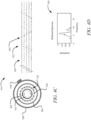
- an asymmetric feature 418 is present outside the casing 208, which may be the anomaly 220.
- the forward wave 402 interacts with the asymmetric feature 418 to create a reflected wave 416.
- the reflected wave 416 travels in a direction opposite to the forward wave 402.
- the reflected wave 416 travels in the clockwise direction. Accordingly, the reflected wave 416 is received by the staves 238 in a reverse order from the forward wave 402.
- signals from the reflected wave 416 is superimposed in the traces.
- Distinctive peaks corresponding to the reflected wave 416 are disposed on notational lines with a negative gradient.
- the forward wave 402 may be distinguished from the reflected wave 416.
- the reflected signals including the peaks 420, 422, and 424 may be combined together and converted from the time domain to the frequency domain to provide a reflected spectrum, as illustrated in a plot 426 shown in Figure 4D .
- the signals may be converted from the time domain to the frequency domain using a Fourier transform or similar transform.
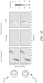
- Figure 4E illustrates a comparison of an effect of eccentricity on the forward and reflected spectra.
- Results for an eccentric configuration 428 of the production tube 206 within the casing 208 is compared with results for a concentric configuration 430 of the production tube 206 within the casing 208.
- the results for each of the configurations includes plots of the forward spectrum, as well as plots of the reflected spectrum where the asymmetrical feature 418 is included (labeled as "Target") and not included (labeled as "No Target”).
- Each of the plots includes angular velocity on the vertical axis and frequency on the horizontal axis with amplitude being depicted on a color intensity scale.
- the production tube 206 generally always provides some form of eccentricity within the casing 208.
- the production tube 206 may be resting against one side of an inner surface of the casing 208, such as in an inclined well, or an axis of the production tube 206 may be at an angle relative to the casing 208. This is particularly true since spacers are often not used to maintain the production tube 206 in the concentric configuration 430, wells are rarely truly vertical, and/or the like.
- the transmitted pulses 404 of the forward wave 402 are chirps with a range of frequencies.
- the forward wave 402 is the result of interaction of the transmitted pulses 404 with material surrounding the casing 208 and includes a spectrum of frequencies at different amplitudes. Stronger amplitudes are shown by darker areas in red. In the example of Figure 4E , the forward wave 402 has strong amplitude components at approximately 4-5 kHz and at approximately 11 kHz over a range of angular velocities. Thus, the forward spectrum for both configurations 428 and 430 contains many modes that propagate at different frequencies and angular velocities, which is characteristic of a dispersive system.
- the reflected spectrum of the reflected wave 416 is shown for each of the configurations 428 and 430. Where there is no target (no asymmetric features), the reflected wave 416 and thus the reflected spectrum is minimal (with only weak signals present, if any), as the forward wave 402 encounters no features that reflect the forward wave 402 sufficient to form the reflected wave 416. Where the asymmetric feature 418 is present, the different acoustic impedance of the asymmetric feature 418 relative to the cement 216 forms the reflected wave 416 with different frequencies and amplitudes depending on the angular velocity of the forward wave 402 and the reflected wave 416.
- the forward spectrum for both the eccentric configuration 428 and the concentric configuration 430 are generally the same.
- the reflected spectrum for both the configuration 428 and the concentric configuration 430 are generally the same when the asymmetrical feature 418 is present and not present. Accordingly, the radial sensor 102 may be used to detect the presence of the asymmetrical 418, regardless of whether there is eccentricity of the production tube 206 relative to the casing 208.
- a data recorder for example integrated with or in communication with the controller 202, utilizes dedicated electronics to record the signals as raw data 500 at a wide bandwidth.
- the data recorder may be set to 10,000 points at 1 ⁇ s per point (1MS/s).
- the raw data 500 may be compressed into compressed data 502 and saved. Every transmission produces a dataset containing receiving waveforms for each of the staves 238. In the example described herein where there are sixteen of the staves 238, each transmission would produce sixteen receiving waveforms.
- the raw data 500 may be saved, for example, at every fourth point giving 2500 points at 4 ⁇ s sampling.
- Stave 0 was the transmitting stave.
- the raw data 500 shows the output of Stave 0, as well as adjacent Stave 1.
- Stave 0 approximates zero voltage due to the short to ground.
- voltage across the resistance amplified by approximately +30dB, shows a chirp of approximately +/-4V.
- Stave 1 also shows a similar chirp due to electrical pickup from the transmitting voltage as a result of the wires having a close proximity.
- the recorded waves in the compressed data 502 are converted to the frequency domain using a Fourier transform.
- the compressed data 502 as a single transmission in time and frequency for all of the staves 238 (e.g., transmission by one stave recorded on all sixteen staves).
- the single transmission of the compressed data 502 may be taken as an Nth transmission and is a function of time and angle, which may be described as m(t, ⁇ ,N).
- Figure 5B illustrates separated waves 504 resulting from the Fourier transform of the compressed data 502.
- the Fourier transform is a function of frequency and wavenumber, which may be described as M(f,k,N), as complex quantity of which only the amplitude is shown.
- a strong wave at approximately 20 kHz had four wavelengths around the casing 208, but at 30kHz, a wave is not present because there is not a mode of propagation that would provide four wavelengths around the casing 208 at a frequency of 30kHz.
- Angular velocity is a ratio of the wavenumber to the frequency, which is illustrated in color. The red color demonstrates that there is primarily one angular velocity of the wave but the other colors show that there are other velocities at which the wave will propagate a well.
- the Fourier transform of the compressed data 502 from the time domain to the frequency domain separates the waves into the separated waves 504.
- the separated waves 504 include clockwise waves and counterclockwise waves. The clockwise waves and the counterclockwise waves each appear twice in the separated waves 504 as complex conjugates.
- the shift function 506 may be defined as S(f,k).
- the sections of the shift function 506 correspond to the clockwise waves and counterclockwise waves, as well as their complex conjugates.
- the counterclockwise waves are shifted -1 and the clockwise waves are shifted +1. Stated differently, the clockwise waves are forward shifted and the counterclockwise waves are backshifted.
- modeling 600 provides an analysis 602 of the production tube 206, and analysis 604 of the casing 208, and an analysis 606 of the production tube 206 within the casing 208 are provided for comparison of wave propagation.
- analysis 602-606 forward waves obtained as described with respect to Figures 5A-5E , with the results including the amplitudes of the forward waves.
- the configurations associated with the analyses 602-606 do not include any asymmetrical features, such that there is no reflected wave.
- the analysis 602 and 604 are characteristic of a dispersive system, where different frequencies travel with different modes. Tangents to the upper and lower ends of the blue line, shown in red, are at 33.6 krad/s and 62.8 krad/s for the analysis 602 and at 28.1 krad/s and 72.4 krad/s for the analysis 604.
- the number of the staves 238 can be in any order based on eccentricity of the production tube 206 and the casing 208.
- the reference to the numbering is for illustration purposes only and not intended to be limiting.
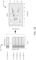
- Each box in this example has a 2.8kHz bandwidth, and Table 1 below provides more detail for each of the boxes: Table 1 Spectrum Center Frequency (kHz) Character F2, R2 14 Provides an amplitude reference, as it is well away from the propagation mode of interest and shows almost no variation with any other parameters.
- F3, R3 9 F3 is sensitive to impedance, such that it may be used to indicate cement, while R3 is sensitive to impedance and highly sensitive to eccentricity and anomalies.
- F2 and R2 may be used as a reference.
- F2 may be used as a reference or calibration.
- F3 may be used to indicate material type, such as cement
- R3 and R5 are highly sensitive to isolation detection and material type identification.
- F4 provides may be used to detect eccentricity
- F7 may be used in combination with F4. Orientation may be found using convolution to detect the axis of symmetry, followed by phase comparison with a known reference to determine axis alignment.
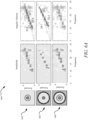
- a first configuration 702 includes air surrounding the casing 208
- a second configuration 704 includes water surrounding the casing 208
- a third configuration 706 includes the cement 216 surrounding the casing 208 for comparison.
- the first configuration 702 includes a water filled channel configuration 708 and an air filled channel configuration 710.
- the second configuration 704 includes an air filled channel configuration 712 and a water filled channel configuration 714.
- the third configuration 706 includes a cement channel configuration 716, a water filled channel configuration 718, and an air filled channel configuration 720.
- the propagating waves are Rayleigh waves.
- the energy cannot easily escape, with the waves being reflected back into the cement 216 at the cement-air boundary.
- the waves are not reflected back into the cement 216 at the cement-formation boundary, instead dissipating into the formation 218.
- the representations 800 show that the wave propagation may characterize the cement 216 and the relationship with the formation 218, without providing unnecessary detail about the characteristics of the formation 218 itself.
- the representations 800 show that at 310 ⁇ s, the Rayleigh waves are outside the casing 208 and by 370 ⁇ s, the Rayleigh waves have travelled to 200mm.
- the Rayleigh waves start to reflect from the air in the top row and decay as energy radiates away as the Rayleigh waves propagate into the formation 218 in the bottom row.
- the Rayleigh waves penetrate about one wavelength from a boundary, such as the casing 208, into a solid medium, such as the formation 218.
- F5 there are five wavelengths around the casing 208.
- ⁇ 144mm.
- the color scale of the representations 800 is logarithmic.
- the pressure decreases by approximately 6dB in the bottom row.
- an object placed at 200mm would have an amplitude of -12dB compared with when the object is placed close to the casing 208.
- This detection threshold of approximately -12dB corresponds to the threshold at which detection of a presence or absence of a target may occur.
- the spectra in F5 and R5 may be focused on features within the detection threshold (e.g., 200mm from the casing 208). This is slightly farther than one wavelength.
- a signal that continues for a long time provides narrow spectral lines, as shown in the top row. Rapid decay of amplitude, as shown in the bottom row, creates wide spectral lines.
- the high impedance of the formation 218 thus causes spectra that are not only fainter due to low amplitude but also appear blurred. Further higher wavenumbers decay more rapidly, with the reflected spectra becoming more blurred, such as from R3 to R6 in Figure 7C for example. Gas or fluid outside the casing 206 would thus provide narrow spectral lines, and the cement 216 would provide wider lines where the cement 216 is bonded to the formation 218.
- isolation regions will appear blurred.
- R3 has narrower line but a longer wavelength, such that it penetrates farther into the formation 218, and R5 has blurred lines with a lower penetration. As such, R3 and R5 combined provide enhanced isolation detection.
- the acoustic waves may be recorded during continual movement of the radial sensor 102 along the production tube 206.
- a transmission sequence 900 includes the staves 238 being pinged in a sequential order as the radial sensor 102 moves axially within the production tube 206.
- the transmitted signals are reflected off collars on both the production tube 206 and the casing 208 used to join axial sections together. These axially reflected waves from the collars will be received by the radial sensor 102 and may interact with radially reflected waves producing false spectral lines.
- a transmission sequence 904 utilizes a non-sequential order (e.g., a random order), where the recorded signals are rearranged based on the known firing sequence of the non-sequential order, thereby avoiding false spectral lines arising from axial waves reflected from the collars.
- a non-sequential order e.g., a random order
- FIG. 10 an example log 1000 of an isolation region.
- the isolation region of the example in Figure 10 is approximately 20m long.
- a configuration 1002 includes the cement 216 outside the casing 208 and the production tube 206. No channel is present.
- a diagram 1004 illustrates the cement 216 with the formation 218 made from different types of rock.
- the cement 216 is continuous in some regions and includes the anomalies 220 in some regions where it is filled with air or water.
- the continuous regions of the cement 216 that are unbroken give a continuous log and show isolation in spectra 1006 of R3 and R5.
- the spectra 1006 of R3 and R5 has low penetration and shows cement, while R3 penetrates farther and provides addition formation details in addition to cement.
- the formation 218 has no features, and may include salt or a similar material which flows.
- R5 shows no changes, as R5 penetrates only into the cement 216.
- R3 has a longer wavelength and this propagates into the formation 218 and detects formation features, such as salt. Knowing that salt is present may be helpful in isolation detection because salt may flow to form a right seal around the casing 208.
- R3 will similarly show no features in the spectra 1006.
- the spectra 1006 will vary in the presence of a channel, as detailed herein.
- multiple casings may be utilized. As described herein, the presently disclosed technology separates the production tube 206 from the casing 208 mathematically using angular velocity. Similarly, multiple casings may be separated based on a difference in the angular velocities. An outer casing will have a similar linear velocity to the casing 206 but because the radius is much larger, the outer casing will have a different angular velocity. Further, each casing may have different sensitive reflection.
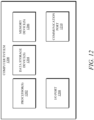
- the computer system 1200 includes one or more ports, such as an input/output (I/O) port 1208 and a communication port 1210, for communicating with other computing, network, or vehicle devices. It will be appreciated that the ports 1208-1210 may be combined or separate and that more or fewer ports may be included in the computer system 1200.
- I/O input/output
- the ports 1208-1210 may be combined or separate and that more or fewer ports may be included in the computer system 1200.
- the environment transducer devices may generate signals to impose some effect on the environment either local to or remote from the example computing device 1200, such as, physical movement of some object (e.g., a mechanical actuator), heating or cooling of a substance, adding a chemical substance, and/or the like.
- some object e.g., a mechanical actuator
- heating or cooling of a substance e.g., heating or cooling of a substance, adding a chemical substance, and/or the like.
- the methods disclosed may be implemented as sets of instructions or software readable by a device. Further, it is understood that the specific order or hierarchy of steps in the methods disclosed are instances of example approaches. Based upon design preferences, it is understood that the specific order or hierarchy of steps in the method can be rearranged while remaining within the disclosed subject matter.
- the accompanying method claims present elements of the various steps in a sample order, and are not necessarily meant to be limited to the specific order or hierarchy presented.
Landscapes
- Physics & Mathematics (AREA)
- Engineering & Computer Science (AREA)
- Life Sciences & Earth Sciences (AREA)
- Geology (AREA)
- Mining & Mineral Resources (AREA)
- Environmental & Geological Engineering (AREA)
- General Life Sciences & Earth Sciences (AREA)
- Geophysics (AREA)
- Acoustics & Sound (AREA)
- Remote Sensing (AREA)
- Geochemistry & Mineralogy (AREA)
- Fluid Mechanics (AREA)
- General Physics & Mathematics (AREA)
- Quality & Reliability (AREA)
- Multimedia (AREA)
- Signal Processing (AREA)
- Health & Medical Sciences (AREA)
- Human Computer Interaction (AREA)
- Audiology, Speech & Language Pathology (AREA)
- Computational Linguistics (AREA)
- Electromagnetism (AREA)
- Spectroscopy & Molecular Physics (AREA)
- Geophysics And Detection Of Objects (AREA)
- Investigating Or Analyzing Materials By The Use Of Ultrasonic Waves (AREA)
Claims (11)
- Procédé mis en œuvre par ordinateur pour la détection d'isolement dans un puits de forage, le procédé mis en œuvre par ordinateur comprenant :l'obtention de données enregistrées comprenant des ondes acoustiques radiales transmises et reçues à l'aide d'un capteur radial (102) d'un outil de diagraphie acoustique (100) déployé dans le puits de forage, dans lequel les ondes acoustiques radiales sont transmises et reçues par le capteur radial à l'aide d'une pluralité de douelles (238), la pluralité de douelles étant disposées autour d'un axe du capteur radial et espacées d'un angle ;la séparation d'un premier ensemble d'ondes des ondes acoustiques radiales d'un second ensemble d'ondes des ondes acoustiques radiales en convertissant les données enregistrées d'un domaine temporel vers un domaine fréquentiel, le premier ensemble d'ondes correspondant à une première direction de propagation radiale et le second ensemble d'ondes correspondant à une seconde direction de propagation radiale ;le décalage du premier ensemble d'ondes en un premier ensemble d'ondes décalées et du second ensemble d'ondes en un second ensemble d'ondes décalées ;la génération d'une onde directe en combinant le premier ensemble d'ondes décalées et d'une onde réfléchie en combinant le second ensemble d'ondes décalées ; etl'identification d'une ou de plusieurs régions d'isolation dans le puits de forage à l'aide de l'onde directe et de l'onde réfléchie, chacune des une ou plusieurs régions d'isolation correspondant à une zone de ciment lié exempte d'anomalies.
- Procédé mis en œuvre par ordinateur de la revendication 1, dans lequel chaque transmission par l'une de la pluralité de douelles est reçue par la totalité de la pluralité de douelles.
- Procédé mis en œuvre par ordinateur de la revendication 1 ou de la revendication 2, dans lequel chaque transmission de la pluralité de douelles est une impulsion chirp.
- Procédé mis en œuvre par ordinateur de l'une quelconque des revendications 1 à 3, dans lequel chaque douelle de la pluralité de douelles comprend une pluralité de plaques (242) câblées en parallèle.
- Procédé mis en œuvre par ordinateur de la revendication 4, dans lequel la pluralité de plaques forment une fenêtre d'interdiction tronquée.
- Procédé mis en œuvre par ordinateur de l'une quelconque des revendications 1 à 5, dans lequel les une ou plusieurs régions d'isolation sont adaptées pour boucher et abandonner le puits de forage.
- Procédé mis en œuvre par ordinateur de l'une quelconque des revendications 1 à 6, dans lequel l'onde directe est transmise avec des retards temporels pour définir une vitesse angulaire.
- Procédé mis en œuvre par ordinateur de l'une quelconque des revendications 1 à 7, dans lequel au moins une partie d'un spectre direct de l'onde directe caractérise l'excentricité.
- Procédé mis en œuvre par ordinateur de l'une quelconque des revendications 1 à 8, dans lequel au moins une partie d'un spectre réfléchi de l'onde réfléchie caractérise au moins un élément parmi une présence d'anomalie ou un type de matériau.
- Procédé mis en œuvre par ordinateur de l'une quelconque des revendications 1 à 9, dans lequel les une ou plusieurs régions d'isolation correspondent à des zones comportant une symétrie radiale.
- Support de stockage lisible par ordinateur tangible et non transitoire ou plusieurs supports de stockage lisibles par ordinateur tangibles et non transitoires stockant des instructions exécutables par ordinateur destinées à réaliser un processus informatique sur un système informatique, le processus informatique comprenant le procédé mis en œuvre par ordinateur de l'une quelconque des revendications 1 à 10.
Applications Claiming Priority (5)
| Application Number | Priority Date | Filing Date | Title |
|---|---|---|---|
| US201962926243P | 2019-10-25 | 2019-10-25 | |
| US201962926228P | 2019-10-25 | 2019-10-25 | |
| US202063032240P | 2020-05-29 | 2020-05-29 | |
| US202063094258P | 2020-10-20 | 2020-10-20 | |
| PCT/US2020/057344 WO2021081492A1 (fr) | 2019-10-25 | 2020-10-26 | Systèmes et procédés d'analyse de liaison de tubage dans un puits à l'aide d'une détection radiale |
Publications (3)
| Publication Number | Publication Date |
|---|---|
| EP4048863A1 EP4048863A1 (fr) | 2022-08-31 |
| EP4048863A4 EP4048863A4 (fr) | 2024-03-27 |
| EP4048863B1 true EP4048863B1 (fr) | 2025-03-26 |
Family
ID=75585641
Family Applications (4)
| Application Number | Title | Priority Date | Filing Date |
|---|---|---|---|
| EP20880242.1A Active EP4048863B1 (fr) | 2019-10-25 | 2020-10-26 | Systèmes et procédés d'analyse de liaison de tubage dans un puits à l'aide d'une détection radiale |
| EP20879978.3A Pending EP4048976A4 (fr) | 2019-10-25 | 2020-10-26 | Systèmes et procédés de détermination de l'excentricité d'un tubage de puits |
| EP20878482.7A Pending EP4049020A4 (fr) | 2019-10-25 | 2020-10-26 | Systèmes et procédés d'analyse d'assemblage de tubage dans un puits à l'aide d'un filtrage de vitesse des ultrasons |
| EP20879562.5A Pending EP4049067A4 (fr) | 2019-10-25 | 2020-10-26 | Systèmes et procédés d'analyse de liaison de tubage dans un puits à l'aide d'une détection différentielle |
Family Applications After (3)
| Application Number | Title | Priority Date | Filing Date |
|---|---|---|---|
| EP20879978.3A Pending EP4048976A4 (fr) | 2019-10-25 | 2020-10-26 | Systèmes et procédés de détermination de l'excentricité d'un tubage de puits |
| EP20878482.7A Pending EP4049020A4 (fr) | 2019-10-25 | 2020-10-26 | Systèmes et procédés d'analyse d'assemblage de tubage dans un puits à l'aide d'un filtrage de vitesse des ultrasons |
| EP20879562.5A Pending EP4049067A4 (fr) | 2019-10-25 | 2020-10-26 | Systèmes et procédés d'analyse de liaison de tubage dans un puits à l'aide d'une détection différentielle |
Country Status (5)
| Country | Link |
|---|---|
| US (4) | US11959377B2 (fr) |
| EP (4) | EP4048863B1 (fr) |
| AU (4) | AU2020369668B2 (fr) |
| CA (3) | CA3155768A1 (fr) |
| WO (4) | WO2021081529A1 (fr) |
Families Citing this family (10)
| Publication number | Priority date | Publication date | Assignee | Title |
|---|---|---|---|---|
| WO2021081529A1 (fr) | 2019-10-25 | 2021-04-29 | Conocophillips Company | Systèmes et procédés d'analyse d'assemblage de tubage dans un puits à l'aide d'un filtrage de vitesse des ultrasons |
| US11970931B2 (en) * | 2021-06-01 | 2024-04-30 | Halliburton Energy Services, Inc. | Through tubing cement evaluation using borehole resonance mode |
| US12078052B2 (en) | 2021-12-06 | 2024-09-03 | Halliburton Energy Services, Inc. | Tubing eccentricity evaluation using acoustic signals |
| US12234716B2 (en) | 2021-12-08 | 2025-02-25 | Halliburton Energy Services, Inc. | Multi-pole resonance based through tubing cement evaluation |
| US12196908B2 (en) | 2021-12-20 | 2025-01-14 | Halliburton Energy Services, Inc. | Through tubing cement evaluation based on casing extensional waves |
| US12032113B2 (en) * | 2022-01-03 | 2024-07-09 | Halliburton Energy Services, Inc. | Through tubing cement evaluation based on rotatable transmitter and computational rotated responses |
| AU2023297915A1 (en) * | 2022-06-28 | 2025-01-09 | Conocophillips Company | Systems and methods for isolation detection using a symmetry invariant log |
| US20240085583A1 (en) * | 2022-09-12 | 2024-03-14 | Baker Hughes Oilfield Operations Llc | System and method for determinations associated with pipe eccentricity |
| US20250243747A1 (en) * | 2024-01-26 | 2025-07-31 | Halliburton Energy Services, Inc. | Ultra-Sonic Acoustic Method For Through Casing Cement Evaluation |
| US20250314795A1 (en) * | 2024-04-04 | 2025-10-09 | Halliburton Energy Services, Inc. | Acoustic road noise removal by adaptive filtering of modeled guided waves |
Family Cites Families (44)
| Publication number | Priority date | Publication date | Assignee | Title |
|---|---|---|---|---|
| US4658383A (en) | 1982-08-23 | 1987-04-14 | Halliburton Company | Automatic gain control of digitized full trace acoustic signal in a borehole |
| US4992994A (en) * | 1989-03-29 | 1991-02-12 | Shell Oil Company | Borehole televiewer for fracture detection and cement evaluation |
| EP1410072A4 (fr) | 2000-10-10 | 2005-08-31 | Exxonmobil Upstream Res Co | Procede de mesure des proprietes de formation d'un trou de forage |
| US6941819B1 (en) | 2001-09-28 | 2005-09-13 | Chandler Instruments Company L.L.C. | Apparatus and method for determining the dynamic mechanical properties of a cement sample |
| US6920082B2 (en) | 2002-06-27 | 2005-07-19 | Baker Hughes Incorporated | Method and apparatus for determining earth formation shear-wave transverse isotropy from borehole stoneley-wave measurements |
| EP1597455B1 (fr) | 2003-02-18 | 2007-09-19 | Baker Hughes Incorporated | Dispositifs de fond de trou a reglage radial et procedes associes |
| US7514930B2 (en) * | 2003-12-02 | 2009-04-07 | Schlumberger Technology Corporation | Apparatus and method for addressing borehole eccentricity effects |
| US7150317B2 (en) | 2004-03-17 | 2006-12-19 | Baker Hughes Incorporated | Use of electromagnetic acoustic transducers in downhole cement evaluation |
| US8020616B2 (en) | 2008-08-15 | 2011-09-20 | Schlumberger Technology Corporation | Determining a status in a wellbore based on acoustic events detected by an optical fiber mechanism |
| US8117907B2 (en) * | 2008-12-19 | 2012-02-21 | Pathfinder Energy Services, Inc. | Caliper logging using circumferentially spaced and/or angled transducer elements |
| US8061206B2 (en) | 2009-04-17 | 2011-11-22 | Baker Hughes Incorporated | Casing thickness evaluation method |
| US20110188347A1 (en) | 2010-01-29 | 2011-08-04 | Schlumberger Technology Corporation | Volume imaging for hydraulic fracture characterization |
| AU2011241963B2 (en) | 2010-04-16 | 2014-03-06 | Schlumberger Technology B.V. | Methods and apparatus to image subsurface formation features |
| EP2540957A1 (fr) | 2011-06-30 | 2013-01-02 | Welltec A/S | Outil d'extraction pour déterminer les dérivations de conduite |
| US8919438B2 (en) | 2011-10-20 | 2014-12-30 | Schlumberger Technology Corporation | Detection and quantification of isolation defects in cement |
| US9494705B2 (en) | 2012-08-13 | 2016-11-15 | Schlumberger Technology Corporation | Cased-hole radial profiling of shear parameters from sonic measurements |
| US9273545B2 (en) | 2012-12-23 | 2016-03-01 | Baker Hughes Incorporated | Use of Lamb and SH attenuations to estimate cement Vp and Vs in cased borehole |
| US10260300B2 (en) * | 2013-12-04 | 2019-04-16 | Baker Hughes, A Ge Company Llc | Measuring formation porosity and permeability |
| US9534487B2 (en) * | 2014-01-16 | 2017-01-03 | Schlumberger Technology Corporation | Cement acoustic properties from ultrasonic signal amplitude dispersions in cased wells |
| WO2015137921A1 (fr) | 2014-03-11 | 2015-09-17 | Halliburton Energy Services, Inc. | Systèmes et procédés de diagraphie par induction multicomposant en utilisant l'inversion du modèle mélangé |
| GB201406131D0 (en) | 2014-04-04 | 2014-05-21 | Epidote Holdings Ltd | System and method for determining deformed pipe geometry |
| WO2016048267A1 (fr) | 2014-09-22 | 2016-03-31 | Halliburton Energy Services, Inc. | Surveillance de l'intégrité d'une gaine de ciment à l'aide d'émissions acoustiques |
| WO2016145524A1 (fr) | 2015-03-16 | 2016-09-22 | Darkvision Technologies Inc. | Dispositif et procédé pour imager un écoulement dans des puits de pétrole et de gaz à l'aide d'ultrasons doppler de réseau à commande de phase |
| WO2016187242A1 (fr) | 2015-05-18 | 2016-11-24 | Schlumberger Technology Corporation | Procédé d'analyse de l'intégrité du ciment dans des colonnes de tubage par apprentissage automatique |
| WO2017007745A1 (fr) * | 2015-07-06 | 2017-01-12 | Schlumberger Technology Corporation | Mesure et traitement pour détecter des couches interfaciales faibles dans des formations stratifiées contenant des hydrocarbures avec des dispositifs de diagraphie acoustique |
| GB2543879A (en) | 2015-07-17 | 2017-05-03 | Conocophillips Co | Well abandonment using vibration to assist cement placement |
| US10222501B2 (en) * | 2016-01-25 | 2019-03-05 | Baker Hughes, A Ge Company, Llc | Televiewer image wood-grain reduction techniques |
| AU2016402342A1 (en) | 2016-04-14 | 2018-09-13 | Halliburton Energy Services Inc. | Acoustic imaging for wellbore investigation |
| CN109563736B (zh) | 2016-06-01 | 2023-03-10 | 斯伦贝谢技术有限公司 | 用于表征地层的系统和方法 |
| US10364664B2 (en) * | 2016-06-30 | 2019-07-30 | Schlumberger Technology Corporation | Downhole acoustic mapping |
| EP3263832A1 (fr) * | 2016-06-30 | 2018-01-03 | Openfield | Procédé et dispositif pour outil de fond de trou de positionnement de profondeur et journal de mesure associé d'un puits d'hydrocarbures |
| US10782433B2 (en) | 2016-07-29 | 2020-09-22 | Baker Hughes Holdings Llc | Method for an automatic detection of acoustic reflectors and their parameters from borehole acoustic array data |
| US10465509B2 (en) | 2016-10-12 | 2019-11-05 | Baker Hughes, A Ge Company, Llc | Collocated multitone acoustic beam and electromagnetic flux leakage evaluation downhole |
| WO2018176024A1 (fr) | 2017-03-24 | 2018-09-27 | Schlumberger Technology Corporation | Formation de faisceau en mode guidé pour sonder des environnements de puits à trou non tubé et trou entubé |
| GB2575395B (en) | 2017-03-27 | 2022-05-25 | Schlumberger Technology Bv | Methods for characterizing multi-string cased wells using wide frequency bandwidth signals |
| US11194069B2 (en) | 2017-12-15 | 2021-12-07 | Halliburton Energy Services, Inc. | Systems and methods for high-resolution travel time and move-out velocity estimation using downhole linear receiver arrays |
| NO344280B1 (en) | 2018-01-25 | 2019-10-28 | Wellguard As | A tool, system and a method for determining barrier and material quality behind multiple tubulars in a hydrocarbon wellbore |
| JP6764886B2 (ja) | 2018-02-02 | 2020-10-07 | 日本電信電話株式会社 | プローブ設置方法および送信プローブの駆動方法 |
| RU2686122C1 (ru) * | 2018-06-14 | 2019-04-24 | Олег Александрович Гурин | Способ определения прохождения перемещающихся объектов в нефтяных, газовых и водных скважинах и мобильное устройство для осуществления данного способа |
| US20200072996A1 (en) | 2018-06-18 | 2020-03-05 | Gowell International, Llc | Method and System of Light-Weight Cement Bond Evaluation by Acoustic Vortex Waves |
| GB2585328B (en) | 2018-12-14 | 2021-07-21 | Darkvision Tech Inc | Correcting for eccentricity of acoustic sensors in wells and pipes |
| US20210017854A1 (en) | 2019-07-15 | 2021-01-21 | Baker Hughes Oilfield Operations Llc | System and method for recovering a slot and forming a whipstock casing exit in a tubular |
| US11542806B2 (en) | 2019-08-19 | 2023-01-03 | Wireless Instrumentation Systems AS | Method and apparatus of untethered casing and bore hole survey through the drill string while tripping out drill pipe |
| WO2021081529A1 (fr) | 2019-10-25 | 2021-04-29 | Conocophillips Company | Systèmes et procédés d'analyse d'assemblage de tubage dans un puits à l'aide d'un filtrage de vitesse des ultrasons |
-
2020
- 2020-10-26 WO PCT/US2020/057418 patent/WO2021081529A1/fr not_active Ceased
- 2020-10-26 WO PCT/US2020/057334 patent/WO2021081487A1/fr not_active Ceased
- 2020-10-26 US US17/080,216 patent/US11959377B2/en active Active
- 2020-10-26 WO PCT/US2020/057415 patent/WO2021081526A1/fr not_active Ceased
- 2020-10-26 EP EP20880242.1A patent/EP4048863B1/fr active Active
- 2020-10-26 CA CA3155768A patent/CA3155768A1/fr active Pending
- 2020-10-26 CA CA3155797A patent/CA3155797A1/fr active Pending
- 2020-10-26 US US17/080,763 patent/US11965411B2/en active Active
- 2020-10-26 CA CA3155783A patent/CA3155783A1/fr active Pending
- 2020-10-26 AU AU2020369668A patent/AU2020369668B2/en active Active
- 2020-10-26 AU AU2020370615A patent/AU2020370615B2/en active Active
- 2020-10-26 AU AU2020369669A patent/AU2020369669B2/en active Active
- 2020-10-26 EP EP20879978.3A patent/EP4048976A4/fr active Pending
- 2020-10-26 WO PCT/US2020/057344 patent/WO2021081492A1/fr not_active Ceased
- 2020-10-26 US US17/080,761 patent/US11879323B2/en active Active
- 2020-10-26 AU AU2020370614A patent/AU2020370614B2/en active Active
- 2020-10-26 EP EP20878482.7A patent/EP4049020A4/fr active Pending
- 2020-10-26 US US17/080,155 patent/US20210123338A1/en active Pending
- 2020-10-26 EP EP20879562.5A patent/EP4049067A4/fr active Pending
Also Published As
| Publication number | Publication date |
|---|---|
| AU2020369669A1 (en) | 2022-05-19 |
| US20210124072A1 (en) | 2021-04-29 |
| EP4049067A4 (fr) | 2023-12-06 |
| WO2021081529A1 (fr) | 2021-04-29 |
| CA3155783A1 (fr) | 2021-04-29 |
| US20210215034A1 (en) | 2021-07-15 |
| EP4049067A1 (fr) | 2022-08-31 |
| EP4048976A1 (fr) | 2022-08-31 |
| US11959377B2 (en) | 2024-04-16 |
| EP4048863A4 (fr) | 2024-03-27 |
| AU2020370614B2 (en) | 2025-10-23 |
| WO2021081492A1 (fr) | 2021-04-29 |
| CA3155804A1 (fr) | 2021-04-29 |
| US20210123339A1 (en) | 2021-04-29 |
| AU2020370615A1 (en) | 2022-05-19 |
| EP4049020A4 (fr) | 2023-11-15 |
| US11879323B2 (en) | 2024-01-23 |
| US20210123338A1 (en) | 2021-04-29 |
| AU2020370614A1 (en) | 2022-05-19 |
| WO2021081487A1 (fr) | 2021-04-29 |
| US11965411B2 (en) | 2024-04-23 |
| CA3155797A1 (fr) | 2021-04-29 |
| EP4049020A1 (fr) | 2022-08-31 |
| EP4048863A1 (fr) | 2022-08-31 |
| AU2020369669B2 (en) | 2025-03-06 |
| AU2020370615B2 (en) | 2025-03-06 |
| WO2021081526A1 (fr) | 2021-04-29 |
| EP4048976A4 (fr) | 2023-12-06 |
| AU2020369668B2 (en) | 2025-12-04 |
| CA3155768A1 (fr) | 2021-04-29 |
| AU2020369668A1 (en) | 2022-05-19 |
Similar Documents
| Publication | Publication Date | Title |
|---|---|---|
| EP4048863B1 (fr) | Systèmes et procédés d'analyse de liaison de tubage dans un puits à l'aide d'une détection radiale | |
| US10809405B2 (en) | Measurement and processing to detect weak interfacial layers in hydrocarbon-bearing laminated formations with acoustic logging devices | |
| US9606254B2 (en) | Determining cement impedance from a formation boundary | |
| WO2015108639A1 (fr) | Diagraphie acoustique d'évaluation d'intégrité de puits | |
| EP3743598B1 (fr) | Dispositif, système et méthode pour déterminer la qualité de barrière et des matériaux derrière des tubulaires multiples dans un puits | |
| US9927541B2 (en) | Apparatus for monopole and multipole sonic logging of a downhole formation | |
| Bose et al. | Acoustic evaluation of annulus b barriers through tubing for plug and abandonment job planning | |
| EP3317699B1 (fr) | Appareil et procédé pour un réseau acoustique de matrice | |
| CN106597549B (zh) | 一种反射波提取方法及装置、反射声波成像测井仪器 | |
| JPH06281631A (ja) | 水力分離決定方法及び装置 | |
| CA3155804C (fr) | Systemes et procedes d'analyse de liaison de tubage dans un puits a l'aide d'une detection radiale | |
| US12282130B2 (en) | Systems and methods for isolation detection using a symmetry invariant log | |
| Kamgang et al. | Cement Bond Logging; A Generational Review of Technologies & Log Interpretation | |
| Ashena et al. | Radial and Ultrasonic CBL and EMAT |
Legal Events
| Date | Code | Title | Description |
|---|---|---|---|
| STAA | Information on the status of an ep patent application or granted ep patent |
Free format text: STATUS: THE INTERNATIONAL PUBLICATION HAS BEEN MADE |
|
| PUAI | Public reference made under article 153(3) epc to a published international application that has entered the european phase |
Free format text: ORIGINAL CODE: 0009012 |
|
| STAA | Information on the status of an ep patent application or granted ep patent |
Free format text: STATUS: REQUEST FOR EXAMINATION WAS MADE |
|
| 17P | Request for examination filed |
Effective date: 20220520 |
|
| AK | Designated contracting states |
Kind code of ref document: A1 Designated state(s): AL AT BE BG CH CY CZ DE DK EE ES FI FR GB GR HR HU IE IS IT LI LT LU LV MC MK MT NL NO PL PT RO RS SE SI SK SM TR |
|
| DAV | Request for validation of the european patent (deleted) | ||
| DAX | Request for extension of the european patent (deleted) | ||
| RIC1 | Information provided on ipc code assigned before grant |
Ipc: E21B 47/12 20120101ALI20231128BHEP Ipc: E21B 47/10 20120101ALI20231128BHEP Ipc: E21B 47/00 20120101ALI20231128BHEP Ipc: E21B 44/00 20060101ALI20231128BHEP Ipc: E21B 47/14 20060101AFI20231128BHEP |
|
| A4 | Supplementary search report drawn up and despatched |
Effective date: 20240228 |
|
| RIC1 | Information provided on ipc code assigned before grant |
Ipc: E21B 47/12 20120101ALI20240222BHEP Ipc: E21B 47/10 20120101ALI20240222BHEP Ipc: E21B 47/00 20120101ALI20240222BHEP Ipc: E21B 44/00 20060101ALI20240222BHEP Ipc: E21B 47/14 20060101AFI20240222BHEP |
|
| GRAP | Despatch of communication of intention to grant a patent |
Free format text: ORIGINAL CODE: EPIDOSNIGR1 |
|
| STAA | Information on the status of an ep patent application or granted ep patent |
Free format text: STATUS: GRANT OF PATENT IS INTENDED |
|
| INTG | Intention to grant announced |
Effective date: 20241025 |
|
| GRAS | Grant fee paid |
Free format text: ORIGINAL CODE: EPIDOSNIGR3 |
|
| GRAA | (expected) grant |
Free format text: ORIGINAL CODE: 0009210 |
|
| STAA | Information on the status of an ep patent application or granted ep patent |
Free format text: STATUS: THE PATENT HAS BEEN GRANTED |
|
| AK | Designated contracting states |
Kind code of ref document: B1 Designated state(s): AL AT BE BG CH CY CZ DE DK EE ES FI FR GB GR HR HU IE IS IT LI LT LU LV MC MK MT NL NO PL PT RO RS SE SI SK SM TR |
|
| P01 | Opt-out of the competence of the unified patent court (upc) registered |
Free format text: CASE NUMBER: APP_7752/2025 Effective date: 20250214 |
|
| REG | Reference to a national code |
Ref country code: GB Ref legal event code: FG4D |
|
| REG | Reference to a national code |
Ref country code: CH Ref legal event code: EP |
|
| REG | Reference to a national code |
Ref country code: DE Ref legal event code: R096 Ref document number: 602020048507 Country of ref document: DE |
|
| REG | Reference to a national code |
Ref country code: IE Ref legal event code: FG4D |
|
| PG25 | Lapsed in a contracting state [announced via postgrant information from national office to epo] |
Ref country code: RS Free format text: LAPSE BECAUSE OF FAILURE TO SUBMIT A TRANSLATION OF THE DESCRIPTION OR TO PAY THE FEE WITHIN THE PRESCRIBED TIME-LIMIT Effective date: 20250626 |
|
| PG25 | Lapsed in a contracting state [announced via postgrant information from national office to epo] |
Ref country code: FI Free format text: LAPSE BECAUSE OF FAILURE TO SUBMIT A TRANSLATION OF THE DESCRIPTION OR TO PAY THE FEE WITHIN THE PRESCRIBED TIME-LIMIT Effective date: 20250326 |
|
| REG | Reference to a national code |
Ref country code: LT Ref legal event code: MG9D |
|
| PG25 | Lapsed in a contracting state [announced via postgrant information from national office to epo] |
Ref country code: HR Free format text: LAPSE BECAUSE OF FAILURE TO SUBMIT A TRANSLATION OF THE DESCRIPTION OR TO PAY THE FEE WITHIN THE PRESCRIBED TIME-LIMIT Effective date: 20250326 |
|
| PG25 | Lapsed in a contracting state [announced via postgrant information from national office to epo] |
Ref country code: LV Free format text: LAPSE BECAUSE OF FAILURE TO SUBMIT A TRANSLATION OF THE DESCRIPTION OR TO PAY THE FEE WITHIN THE PRESCRIBED TIME-LIMIT Effective date: 20250326 |
|
| PG25 | Lapsed in a contracting state [announced via postgrant information from national office to epo] |
Ref country code: GR Free format text: LAPSE BECAUSE OF FAILURE TO SUBMIT A TRANSLATION OF THE DESCRIPTION OR TO PAY THE FEE WITHIN THE PRESCRIBED TIME-LIMIT Effective date: 20250627 Ref country code: BG Free format text: LAPSE BECAUSE OF FAILURE TO SUBMIT A TRANSLATION OF THE DESCRIPTION OR TO PAY THE FEE WITHIN THE PRESCRIBED TIME-LIMIT Effective date: 20250326 |
|
| REG | Reference to a national code |
Ref country code: NL Ref legal event code: MP Effective date: 20250326 |
|
| PG25 | Lapsed in a contracting state [announced via postgrant information from national office to epo] |
Ref country code: NL Free format text: LAPSE BECAUSE OF FAILURE TO SUBMIT A TRANSLATION OF THE DESCRIPTION OR TO PAY THE FEE WITHIN THE PRESCRIBED TIME-LIMIT Effective date: 20250326 |
|
| PG25 | Lapsed in a contracting state [announced via postgrant information from national office to epo] |
Ref country code: SE Free format text: LAPSE BECAUSE OF FAILURE TO SUBMIT A TRANSLATION OF THE DESCRIPTION OR TO PAY THE FEE WITHIN THE PRESCRIBED TIME-LIMIT Effective date: 20250326 |
|
| REG | Reference to a national code |
Ref country code: AT Ref legal event code: MK05 Ref document number: 1779143 Country of ref document: AT Kind code of ref document: T Effective date: 20250326 |
|
| PG25 | Lapsed in a contracting state [announced via postgrant information from national office to epo] |
Ref country code: SM Free format text: LAPSE BECAUSE OF FAILURE TO SUBMIT A TRANSLATION OF THE DESCRIPTION OR TO PAY THE FEE WITHIN THE PRESCRIBED TIME-LIMIT Effective date: 20250326 |
|
| PG25 | Lapsed in a contracting state [announced via postgrant information from national office to epo] |
Ref country code: ES Free format text: LAPSE BECAUSE OF FAILURE TO SUBMIT A TRANSLATION OF THE DESCRIPTION OR TO PAY THE FEE WITHIN THE PRESCRIBED TIME-LIMIT Effective date: 20250326 Ref country code: PT Free format text: LAPSE BECAUSE OF FAILURE TO SUBMIT A TRANSLATION OF THE DESCRIPTION OR TO PAY THE FEE WITHIN THE PRESCRIBED TIME-LIMIT Effective date: 20250728 |
|
| PG25 | Lapsed in a contracting state [announced via postgrant information from national office to epo] |
Ref country code: IT Free format text: LAPSE BECAUSE OF FAILURE TO SUBMIT A TRANSLATION OF THE DESCRIPTION OR TO PAY THE FEE WITHIN THE PRESCRIBED TIME-LIMIT Effective date: 20250326 Ref country code: PL Free format text: LAPSE BECAUSE OF FAILURE TO SUBMIT A TRANSLATION OF THE DESCRIPTION OR TO PAY THE FEE WITHIN THE PRESCRIBED TIME-LIMIT Effective date: 20250326 |
|
| PG25 | Lapsed in a contracting state [announced via postgrant information from national office to epo] |
Ref country code: AT Free format text: LAPSE BECAUSE OF FAILURE TO SUBMIT A TRANSLATION OF THE DESCRIPTION OR TO PAY THE FEE WITHIN THE PRESCRIBED TIME-LIMIT Effective date: 20250326 |
|
| PG25 | Lapsed in a contracting state [announced via postgrant information from national office to epo] |
Ref country code: EE Free format text: LAPSE BECAUSE OF FAILURE TO SUBMIT A TRANSLATION OF THE DESCRIPTION OR TO PAY THE FEE WITHIN THE PRESCRIBED TIME-LIMIT Effective date: 20250326 |
|
| PG25 | Lapsed in a contracting state [announced via postgrant information from national office to epo] |
Ref country code: RO Free format text: LAPSE BECAUSE OF FAILURE TO SUBMIT A TRANSLATION OF THE DESCRIPTION OR TO PAY THE FEE WITHIN THE PRESCRIBED TIME-LIMIT Effective date: 20250326 |
|
| PG25 | Lapsed in a contracting state [announced via postgrant information from national office to epo] |
Ref country code: SK Free format text: LAPSE BECAUSE OF FAILURE TO SUBMIT A TRANSLATION OF THE DESCRIPTION OR TO PAY THE FEE WITHIN THE PRESCRIBED TIME-LIMIT Effective date: 20250326 |
|
| PG25 | Lapsed in a contracting state [announced via postgrant information from national office to epo] |
Ref country code: IS Free format text: LAPSE BECAUSE OF FAILURE TO SUBMIT A TRANSLATION OF THE DESCRIPTION OR TO PAY THE FEE WITHIN THE PRESCRIBED TIME-LIMIT Effective date: 20250726 |
|
| REG | Reference to a national code |
Ref country code: DE Ref legal event code: R097 Ref document number: 602020048507 Country of ref document: DE |
|
| PGFP | Annual fee paid to national office [announced via postgrant information from national office to epo] |
Ref country code: GB Payment date: 20251022 Year of fee payment: 6 |
|
| PGFP | Annual fee paid to national office [announced via postgrant information from national office to epo] |
Ref country code: NO Payment date: 20251024 Year of fee payment: 6 |
|
| PG25 | Lapsed in a contracting state [announced via postgrant information from national office to epo] |
Ref country code: DK Free format text: LAPSE BECAUSE OF FAILURE TO SUBMIT A TRANSLATION OF THE DESCRIPTION OR TO PAY THE FEE WITHIN THE PRESCRIBED TIME-LIMIT Effective date: 20250326 |
|
| PG25 | Lapsed in a contracting state [announced via postgrant information from national office to epo] |
Ref country code: CZ Free format text: LAPSE BECAUSE OF FAILURE TO SUBMIT A TRANSLATION OF THE DESCRIPTION OR TO PAY THE FEE WITHIN THE PRESCRIBED TIME-LIMIT Effective date: 20250326 |
|
| PLBE | No opposition filed within time limit |
Free format text: ORIGINAL CODE: 0009261 |
|
| STAA | Information on the status of an ep patent application or granted ep patent |
Free format text: STATUS: NO OPPOSITION FILED WITHIN TIME LIMIT |
|
| REG | Reference to a national code |
Ref country code: CH Ref legal event code: L10 Free format text: ST27 STATUS EVENT CODE: U-0-0-L10-L00 (AS PROVIDED BY THE NATIONAL OFFICE) Effective date: 20260211 |
|
| 26N | No opposition filed |
Effective date: 20260105 |