EP4048878B1 - Viertakt-verbrennungsmotor und verfahren zur steuerung der taktungen einer auslassnockenwelle und einer einlassnockenwelle - Google Patents
Viertakt-verbrennungsmotor und verfahren zur steuerung der taktungen einer auslassnockenwelle und einer einlassnockenwelle Download PDFInfo
- Publication number
- EP4048878B1 EP4048878B1 EP20879502.1A EP20879502A EP4048878B1 EP 4048878 B1 EP4048878 B1 EP 4048878B1 EP 20879502 A EP20879502 A EP 20879502A EP 4048878 B1 EP4048878 B1 EP 4048878B1
- Authority
- EP
- European Patent Office
- Prior art keywords
- exhaust
- timing
- camshaft
- compressor
- current
- Prior art date
- Legal status (The legal status is an assumption and is not a legal conclusion. Google has not performed a legal analysis and makes no representation as to the accuracy of the status listed.)
- Active
Links
Images




Classifications
-
- F—MECHANICAL ENGINEERING; LIGHTING; HEATING; WEAPONS; BLASTING
- F02—COMBUSTION ENGINES; HOT-GAS OR COMBUSTION-PRODUCT ENGINE PLANTS
- F02B—INTERNAL-COMBUSTION PISTON ENGINES; COMBUSTION ENGINES IN GENERAL
- F02B37/00—Engines characterised by provision of pumps driven at least for part of the time by exhaust
- F02B37/12—Control of the pumps
-
- F—MECHANICAL ENGINEERING; LIGHTING; HEATING; WEAPONS; BLASTING
- F02—COMBUSTION ENGINES; HOT-GAS OR COMBUSTION-PRODUCT ENGINE PLANTS
- F02D—CONTROLLING COMBUSTION ENGINES
- F02D13/00—Controlling the engine output power by varying inlet or exhaust valve operating characteristics, e.g. timing
- F02D13/02—Controlling the engine output power by varying inlet or exhaust valve operating characteristics, e.g. timing during engine operation
- F02D13/0203—Variable control of intake and exhaust valves
- F02D13/0215—Variable control of intake and exhaust valves changing the valve timing only
- F02D13/0219—Variable control of intake and exhaust valves changing the valve timing only by shifting the phase, i.e. the opening periods of the valves are constant
-
- F—MECHANICAL ENGINEERING; LIGHTING; HEATING; WEAPONS; BLASTING
- F01—MACHINES OR ENGINES IN GENERAL; ENGINE PLANTS IN GENERAL; STEAM ENGINES
- F01L—CYCLICALLY OPERATING VALVES FOR MACHINES OR ENGINES
- F01L1/00—Valve-gear or valve arrangements, e.g. lift-valve gear
- F01L1/34—Valve-gear or valve arrangements, e.g. lift-valve gear characterised by the provision of means for changing the timing of the valves without changing the duration of opening and without affecting the magnitude of the valve lift
-
- F—MECHANICAL ENGINEERING; LIGHTING; HEATING; WEAPONS; BLASTING
- F02—COMBUSTION ENGINES; HOT-GAS OR COMBUSTION-PRODUCT ENGINE PLANTS
- F02D—CONTROLLING COMBUSTION ENGINES
- F02D13/00—Controlling the engine output power by varying inlet or exhaust valve operating characteristics, e.g. timing
- F02D13/02—Controlling the engine output power by varying inlet or exhaust valve operating characteristics, e.g. timing during engine operation
- F02D13/0203—Variable control of intake and exhaust valves
- F02D13/0215—Variable control of intake and exhaust valves changing the valve timing only
-
- F—MECHANICAL ENGINEERING; LIGHTING; HEATING; WEAPONS; BLASTING
- F02—COMBUSTION ENGINES; HOT-GAS OR COMBUSTION-PRODUCT ENGINE PLANTS
- F02D—CONTROLLING COMBUSTION ENGINES
- F02D13/00—Controlling the engine output power by varying inlet or exhaust valve operating characteristics, e.g. timing
- F02D13/02—Controlling the engine output power by varying inlet or exhaust valve operating characteristics, e.g. timing during engine operation
- F02D13/0261—Controlling the valve overlap
-
- F—MECHANICAL ENGINEERING; LIGHTING; HEATING; WEAPONS; BLASTING
- F02—COMBUSTION ENGINES; HOT-GAS OR COMBUSTION-PRODUCT ENGINE PLANTS
- F02D—CONTROLLING COMBUSTION ENGINES
- F02D13/00—Controlling the engine output power by varying inlet or exhaust valve operating characteristics, e.g. timing
- F02D13/02—Controlling the engine output power by varying inlet or exhaust valve operating characteristics, e.g. timing during engine operation
- F02D13/0261—Controlling the valve overlap
- F02D13/0265—Negative valve overlap for temporarily storing residual gas in the cylinder
-
- F—MECHANICAL ENGINEERING; LIGHTING; HEATING; WEAPONS; BLASTING
- F02—COMBUSTION ENGINES; HOT-GAS OR COMBUSTION-PRODUCT ENGINE PLANTS
- F02D—CONTROLLING COMBUSTION ENGINES
- F02D13/00—Controlling the engine output power by varying inlet or exhaust valve operating characteristics, e.g. timing
- F02D13/02—Controlling the engine output power by varying inlet or exhaust valve operating characteristics, e.g. timing during engine operation
- F02D13/04—Controlling the engine output power by varying inlet or exhaust valve operating characteristics, e.g. timing during engine operation using engine as brake
-
- F—MECHANICAL ENGINEERING; LIGHTING; HEATING; WEAPONS; BLASTING
- F02—COMBUSTION ENGINES; HOT-GAS OR COMBUSTION-PRODUCT ENGINE PLANTS
- F02D—CONTROLLING COMBUSTION ENGINES
- F02D41/00—Electrical control of supply of combustible mixture or its constituents
- F02D41/0002—Controlling intake air
- F02D41/0007—Controlling intake air for control of turbo-charged or super-charged engines
-
- F—MECHANICAL ENGINEERING; LIGHTING; HEATING; WEAPONS; BLASTING
- F02—COMBUSTION ENGINES; HOT-GAS OR COMBUSTION-PRODUCT ENGINE PLANTS
- F02D—CONTROLLING COMBUSTION ENGINES
- F02D41/00—Electrical control of supply of combustible mixture or its constituents
- F02D41/02—Circuit arrangements for generating control signals
- F02D41/14—Introducing closed-loop corrections
- F02D41/1438—Introducing closed-loop corrections using means for determining characteristics of the combustion gases; Sensors therefor
- F02D41/1444—Introducing closed-loop corrections using means for determining characteristics of the combustion gases; Sensors therefor characterised by the characteristics of the combustion gases
- F02D41/1454—Introducing closed-loop corrections using means for determining characteristics of the combustion gases; Sensors therefor characterised by the characteristics of the combustion gases the characteristics being an oxygen content or concentration or the air-fuel ratio
-
- F—MECHANICAL ENGINEERING; LIGHTING; HEATING; WEAPONS; BLASTING
- F02—COMBUSTION ENGINES; HOT-GAS OR COMBUSTION-PRODUCT ENGINE PLANTS
- F02D—CONTROLLING COMBUSTION ENGINES
- F02D41/00—Electrical control of supply of combustible mixture or its constituents
- F02D41/02—Circuit arrangements for generating control signals
- F02D41/18—Circuit arrangements for generating control signals by measuring intake air flow
-
- F—MECHANICAL ENGINEERING; LIGHTING; HEATING; WEAPONS; BLASTING
- F02—COMBUSTION ENGINES; HOT-GAS OR COMBUSTION-PRODUCT ENGINE PLANTS
- F02D—CONTROLLING COMBUSTION ENGINES
- F02D41/00—Electrical control of supply of combustible mixture or its constituents
- F02D41/24—Electrical control of supply of combustible mixture or its constituents characterised by the use of digital means
- F02D41/2406—Electrical control of supply of combustible mixture or its constituents characterised by the use of digital means using essentially read only memories
- F02D41/2409—Addressing techniques specially adapted therefor
- F02D41/2422—Selective use of one or more tables
-
- F—MECHANICAL ENGINEERING; LIGHTING; HEATING; WEAPONS; BLASTING
- F01—MACHINES OR ENGINES IN GENERAL; ENGINE PLANTS IN GENERAL; STEAM ENGINES
- F01L—CYCLICALLY OPERATING VALVES FOR MACHINES OR ENGINES
- F01L13/00—Modifications of valve-gear to facilitate reversing, braking, starting, changing compression ratio, or other specific operations
- F01L13/06—Modifications of valve-gear to facilitate reversing, braking, starting, changing compression ratio, or other specific operations for braking
- F01L13/065—Compression release engine retarders of the "Jacobs Manufacturing" type
-
- F—MECHANICAL ENGINEERING; LIGHTING; HEATING; WEAPONS; BLASTING
- F02—COMBUSTION ENGINES; HOT-GAS OR COMBUSTION-PRODUCT ENGINE PLANTS
- F02B—INTERNAL-COMBUSTION PISTON ENGINES; COMBUSTION ENGINES IN GENERAL
- F02B37/00—Engines characterised by provision of pumps driven at least for part of the time by exhaust
- F02B37/12—Control of the pumps
- F02B2037/125—Control for avoiding pump stall or surge
-
- F—MECHANICAL ENGINEERING; LIGHTING; HEATING; WEAPONS; BLASTING
- F02—COMBUSTION ENGINES; HOT-GAS OR COMBUSTION-PRODUCT ENGINE PLANTS
- F02D—CONTROLLING COMBUSTION ENGINES
- F02D41/00—Electrical control of supply of combustible mixture or its constituents
- F02D41/0002—Controlling intake air
- F02D2041/001—Controlling intake air for engines with variable valve actuation
-
- F—MECHANICAL ENGINEERING; LIGHTING; HEATING; WEAPONS; BLASTING
- F02—COMBUSTION ENGINES; HOT-GAS OR COMBUSTION-PRODUCT ENGINE PLANTS
- F02D—CONTROLLING COMBUSTION ENGINES
- F02D2200/00—Input parameters for engine control
- F02D2200/02—Input parameters for engine control the parameters being related to the engine
- F02D2200/024—Fluid pressure of lubricating oil or working fluid
-
- F—MECHANICAL ENGINEERING; LIGHTING; HEATING; WEAPONS; BLASTING
- F02—COMBUSTION ENGINES; HOT-GAS OR COMBUSTION-PRODUCT ENGINE PLANTS
- F02D—CONTROLLING COMBUSTION ENGINES
- F02D2200/00—Input parameters for engine control
- F02D2200/02—Input parameters for engine control the parameters being related to the engine
- F02D2200/04—Engine intake system parameters
- F02D2200/0406—Intake manifold pressure
-
- F—MECHANICAL ENGINEERING; LIGHTING; HEATING; WEAPONS; BLASTING
- F02—COMBUSTION ENGINES; HOT-GAS OR COMBUSTION-PRODUCT ENGINE PLANTS
- F02D—CONTROLLING COMBUSTION ENGINES
- F02D2200/00—Input parameters for engine control
- F02D2200/02—Input parameters for engine control the parameters being related to the engine
- F02D2200/04—Engine intake system parameters
- F02D2200/0414—Air temperature
-
- F—MECHANICAL ENGINEERING; LIGHTING; HEATING; WEAPONS; BLASTING
- F02—COMBUSTION ENGINES; HOT-GAS OR COMBUSTION-PRODUCT ENGINE PLANTS
- F02D—CONTROLLING COMBUSTION ENGINES
- F02D2200/00—Input parameters for engine control
- F02D2200/02—Input parameters for engine control the parameters being related to the engine
- F02D2200/10—Parameters related to the engine output, e.g. engine torque or engine speed
- F02D2200/101—Engine speed
-
- Y—GENERAL TAGGING OF NEW TECHNOLOGICAL DEVELOPMENTS; GENERAL TAGGING OF CROSS-SECTIONAL TECHNOLOGIES SPANNING OVER SEVERAL SECTIONS OF THE IPC; TECHNICAL SUBJECTS COVERED BY FORMER USPC CROSS-REFERENCE ART COLLECTIONS [XRACs] AND DIGESTS
- Y02—TECHNOLOGIES OR APPLICATIONS FOR MITIGATION OR ADAPTATION AGAINST CLIMATE CHANGE
- Y02T—CLIMATE CHANGE MITIGATION TECHNOLOGIES RELATED TO TRANSPORTATION
- Y02T10/00—Road transport of goods or passengers
- Y02T10/10—Internal combustion engine [ICE] based vehicles
- Y02T10/12—Improving ICE efficiencies
Definitions
- the invention relates to a four-stroke internal combustion engine and to a method of controlling timings of an exhaust camshaft and an intake camshaft of a four-stroke internal combustion engine.
- the invention further relates to a vehicle comprising a four-stroke internal combustion engine.
- the invention relates to a computer program and to a computer-readable storage medium.
- a turbocharger of an internal combustion engine increases the density of the charge air being admitted into the ICE for combustion of a fuel within the ICE.
- An increased charge air density permits combustion of larger amounts of fuel, which in turn means that the ICE produces a higher power output than with uncompressed charge air.
- the turbocharger comprises a compressor and a turbine which are connected by a common shaft. The turbine is driven by the exhaust gas from the ICE.
- a turbocharger of an ICE has an operating range which is matched in size for that particular ICE.
- the turbocharger would be adapted to provide an optimal amount of charge air to the ICE over the entire operating range of the ICE.
- due to inter alia mechanical limitations of the turbocharger and the width of the operating range of the ICE this it is not possible.
- a well matched turbocharger provides at least sufficient charge air over a large part of the ICE operating range. That said, there are operating conditions, under which the turbocharger has limited performance. Under such operating conditions, the performance of the ICE is limited as well.
- a wastegate forms a bypass of the turbine of the turbocharger.
- the amount of exhaust gas passing through the turbine may be controlled by opening and closing the wastegate, which permits the compressor of the turbocharger to be operated within its operating range. For instance, at higher engine speeds the wastegate may be opened in order to control the turbocharger speed, i.e. the energy flow to the turbine is reduced via the wastegate, and thus, the charge air pressure produced by the compressor is reduced.
- WO 2010/058082 discloses a method of controlling turbocharger speed of a piston engine in which method the engine is operated below or at a predetermined load and combustion air is pressurised with the compressor part.
- the engine may be run in various modes of operation including one or more of bypassing charge air from the compressor to the turbine, advancing or delaying opening and closing of the valves utilising a so-called lost motion mechanism according to WO 2008/000899 .
- US 2004/0089278 discloses an ICE with an exhaust-driven turbocompressor and with a divided exhaust gas flow having at least two exhaust valves and one intake valve per cylinder.
- a first exhaust valve is connected to a first exhaust manifold which leads to the turbine of the compressor, while a second exhaust valve is connected to a second exhaust manifold which opens downstream of the turbine.
- the charging pressure in the engine can be regulated by virtue of the opening periods of the at least two exhaust valves being varied in relation to one another in order to adapt the flow through the exhaust turbine to a value which provides the desired charging pressure in the engine.
- By opening the second exhaust valve increasingly earlier, an increasingly lower charging pressure can be achieved.
- WO2013/109249 discloses a turbocharged IC engine wherein a variable valve actuation mechanism and waste gate valve are operated to control the pressure in the exhaust manifold.
- US 2009/0018751 discloses another concept of varying of the valve operation of the cylinders when the waste gate position of the turbocharger is adjusted.
- a four-stroke internal combustion engine having the features defined in one of the independent claims is provided, and according to a further aspect, a method of controlling timings of an exhaust camshaft and an intake camshaft of a four-stroke internal combustion engine defined in one of the independent claims is provided.
- a four-stroke internal combustion engine comprising at least one cylinder arrangement, a crankshaft, an exhaust camshaft, an intake camshaft, a turbocharger, and a control system.
- the cylinder arrangement comprises a combustion chamber, a cylinder bore, a piston configured to reciprocate in the cylinder bore and being connected to the crankshaft, an exhaust valve, and an intake valve.
- the exhaust camshaft is configured to control the opening and closing of the exhaust valve
- the intake camshaft is configured to control the opening and closing of the intake valve.
- the turbocharger comprises a compressor and a turbine, the turbine being arranged in an exhaust gas flow path extending from the exhaust valve. A timing of the exhaust camshaft and a timing of the intake camshaft are controllable by the control system.
- the control system is configured to:
- control system in response to the at least two parameters indicating that a current operational point of the compressor is outside the reference area at a higher charge air mass flow than a maximum charge air mass flow of the reference area at a compressor pressure ratio of the current operational point, is configured to: - change the timing of the exhaust camshaft to advance closing of the exhaust valve, and - change the timing of the intake camshaft to delay opening of the intake valve, no wastegate is required for reducing the charge air pressure provided by the compressor of the turbocharger.
- a method of controlling timings of an exhaust camshaft and an intake camshaft of a four-stroke internal combustion engine comprising at least one cylinder arrangement, a crankshaft, the exhaust camshaft, the intake camshaft, a turbocharger, and a control system.
- the cylinder arrangement comprises a combustion chamber, a cylinder bore, a piston configured to reciprocate in the cylinder bore and being connected to the crankshaft, an exhaust valve, and an intake valve.
- the exhaust camshaft is configured to control the opening and closing of the exhaust valve
- the intake camshaft is configured to control the opening and closing of the intake valve.
- the turbocharger comprises a compressor and a turbine, the turbine being arranged in an exhaust gas flow path extending from the exhaust valve.
- the control system is configured to store a compressor map related to the compressor of the turbocharger, and to store a reference area within the compressor map. The method comprises steps of:
- the method comprises steps of: - changing the timing of the exhaust camshaft to advance closing of the exhaust valve, and - changing the timing of the intake camshaft to delay opening of the intake valve, in response to a step of: - detecting whether the at least two parameters indicate that a current operational point of the compressor is outside the reference area at a higher charge air mass flow than a maximum charge air mass flow of the reference area at a compressor pressure ratio of the current operational point, no wastegate is required for reducing the charge air pressure provided by the compressor of the turbocharger.
- the inventors have realised that changing the timing of camshafts in order to advance closing of the exhaust valve and delay opening of the intake valve may be utilised for controlling the operation of the turbocharger.
- Such change of timing of the camshafts reduces exhaust gas flow from the combustion chamber to the turbine of the turbocharger.
- the control of the operation of the turbocharger may be utilised e.g. for preventing choking of the compressor of the turbocharger, and/or for moving a current operational point of the compressor towards an operational point where the compressor operates more efficiently.
- the four-stroke internal combustion engine, ICE may be a compression ignition ICE, such as a diesel engine, alternatively, the ICE may be an Otto engine.
- the four-stroke ICE alternatively may be simply referred to as an internal combustion engine, ICE.
- the piston performs an intake stroke, a compression stroke, a power stroke, and an exhaust stroke in the cylinder bore of the cylinder arrangement.
- the ICE may comprise more than one cylinder arrangement, such as e.g. four, five, six, or eight cylinder arrangements.
- the exhaust camshaft is configured to control the opening and closing of the exhaust valve in a commonly known manner with a cam lobe of the exhaust camshaft controlling the exhaust valve.
- the intake camshaft is configured to control the opening and closing of the intake valve in a commonly known manner with a cam lobe of the intake camshaft controlling the intake valve.
- the compressor and the turbine of the turbocharger are connected via a common shaft.
- the exhaust gas flow path may extend from the exhaust valve via the turbine to an aftertreatment system for exhaust gas.
- the exhaust gas flow path extends also from the one or more further exhaust valves via the turbine to the exhaust gas aftertreatment system.
- An intake air flow path extends via the compressor to the intake valve.
- the rotation of the exhaust and intake camshafts are synchronized with the crankshaft.
- the timing of the exhaust and intake camshafts being controllable entails that the rotational position of the camshafts in relation to the crankshaft is changeable. This may also be referred to as cam phasing. In practice, this means that the crankshaft angle at which a valve controlled by the relevant camshaft is opened and closed can be changed.
- the changing of the timing of the camshafts may be performed in any known manner. For instance, WO 2017/217908 and US 8714123 disclose suitable timing control arrangements to be utilised for changing the timing of the camshafts.
- the timings of the exhaust and intake camshafts are controllable by the control system, i.e. the control system is configured to change the rotational position of the camshafts in relation to the crankshaft.
- the amount of timing change of the camshafts may be one fixed amount of timing change for each camshaft.
- each camshaft may have a variable amount of timing change providing at least two different amounts of timing change to provide different amount of exhaust gas flowing through the exhaust path.
- crankshaft angle degrees CA degrees
- One full rotation of the crankshaft is 360 CA degrees.
- Crankshaft angle may be measured e.g. from Top Dead Centre fire, TDCfire, or Top Dead Centre gas exchange, TDCge.
- the cylinder arrangement comprises one or more additional intake valves and/or exhaust valves, also these valves have to open and close in the manner discussed above, which will occur if such additional valves are controlled by the first and/or second camshafts. Accordingly, if the additional valves are controlled by additional camshafts, also the timing of any additional camshafts will be changed in accordance with the discussion above.
- a compressor map is a commonly known map showing the operational range of a particular type of compressor, i.e. in this case the compressor of the relevant turbocharger of the ICE.
- the compressor map may be defined as a field in a coordinate system having axes expressing charge air mass flow and compressor pressure ratio, i.e. the relationship between the charge air pressure after and before the compressor, p out : p in .
- reference area relates to an area of the compressor map.
- the reference area may cover the entire compressor map, or it may cover only part of the compressor map.
- the reference area may even be formed by one point within the compressor map.
- the reference area may represent an optimal operational range, or an optimal operational point, of the compressor within the compressor map, such as e.g.:
- control system may be configured to, in response to the at least two parameters indicating that a current operational point of the compressor being outside the reference area at a lower charge air mass flow than a minimum charge air mass flow of the reference area at a compressor pressure ration of the current operational point:
- the exhaust gas flow path may in its entirety extend through the turbine. In this manner, all exhaust gas from the cylinder arrangement passes through the turbine.
- the turbine forms an only flow path portion leading from the cylinder arrangement to exhaust gas aftertreatment equipment downstream of the turbine, i.e. there is no parallel flow path to the turbine that leads to the exhaust gas aftertreatment equipment.
- no further flow path for exhaust gas from the cylinder arrangement extends in parallel with the exhaust gas flow path.
- control system may be configured to:
- control system may be configured to:
- control system in response to the current lambda value being below the target lambda value or lambda value range, may be configured to:
- the change of the timing of the exhaust camshaft to advance closing of the exhaust valve in advancing CA degrees may be of an equal magnitude as, or may differ within a range of maximum +/- 10 CA degrees from, the change of the timing of the intake camshaft to delay opening of the intake valve in delay CA degrees.
- a substantially symmetrical camshaft phasing about TDCge may be achieved.
- Symmetrical camshaft phasing about TDCge may improve fuel consumption of the ICE when advancing closing of the exhaust valve and delaying opening of the intake valve in comparison with providing only early closing of the exhaust valve or only late opening of the intake valve.
- a vehicle comprising a four-stroke internal combustion engine according to any one of aspects and/or embodiments discussed herein.
- the vehicle may be a heavy load vehicle such as e.g. a truck, a bus, a construction vehicle, a pickup, a van, or other similar motorized manned or unmanned vehicle, designed for land-based propulsion, on or off road.
- a heavy load vehicle such as e.g. a truck, a bus, a construction vehicle, a pickup, a van, or other similar motorized manned or unmanned vehicle, designed for land-based propulsion, on or off road.
- a computer program comprising instructions which, when the program is executed by a computer, causes the computer to carry out a method according to any one of aspects and/or embodiments discussed herein.
- a computer-readable storage medium comprising instructions which, when executed by a computer, cause the computer to carry out a method according to any one of aspects and/or embodiments discussed herein.
- Fig. 1 illustrates embodiments of a vehicle 2 configured for land-based propulsion.
- the vehicle 2 comprises a four-stroke internal combustion engine, ICE, 4 according to aspects and/or embodiments discussed herein, such as e.g. the ICE discussed below with reference to Fig. 2 .
- the vehicle 2 is a heavy load vehicle in the form of a truck.
- the invention is not limited to the particular type of vehicle.
- Fig. 2 schematically illustrates embodiments of an ICE 4.
- the ICE 4 may be configured to form part of a powertrain of a vehicle, such as e.g. the vehicle 2 shown in Fig. 1 .
- the ICE 4 is a four-stroke direct injection internal combustion engine, such as a compression ignition ICE 4, e.g. a diesel engine.
- the ICE 4 comprises at least one cylinder arrangement 6, a crankshaft 8, an exhaust camshaft 10, an intake camshaft 12, and a turbocharger 14.
- the cylinder arrangement 6 comprises a combustion chamber 16, a fuel injector 18, an exhaust valve 20, an intake valve 22, a cylinder bore 24, and a piston 26 configured to reciprocate in the cylinder bore 24.
- the piston 26 is connected to the crankshaft 8 via a connecting rod 27.
- the movement of the exhaust valve 20 is controlled by the exhaust camshaft 10, i.e. the exhaust camshaft 10 is configured to control the opening and closing of the exhaust valve 20.
- the movement of the intake valve 22 is controlled by the intake camshaft 12, i.e. the intake camshaft 12 is configured to control the opening and closing of the intake valve 22.
- the intake valve 22 is configured for admitting charge air into the combustion chamber 16, and the exhaust valve 20 is configured for letting exhaust gas out of the combustion chamber 16.
- the timing of the exhaust camshaft 10 is configured to the be controlled by a timing control arrangement 30 as indicated by a double arrow.
- the timing of the intake camshaft 12 is configured to the be controlled by a timing control arrangement 32 as indicated by a double arrow.
- the piston 26 is arranged to reciprocate in the cylinder bore 24.
- the piston 26 performs four strokes in the cylinder bore 24, corresponding to an intake stroke, a compression stroke, a power stroke, and an exhaust stroke, see also Fig. 5 .
- the piston 26 is illustrated with continuous lines at its Bottom Dead Centre, BDC, and with dashed lines at its Top Dead Centre, TDC.
- the combustion chamber 16 is formed above the piston 26 inside the cylinder bore 24.
- the intake valve 22 comprises an intake valve head configured to seal against an intake valve seat extending around an intake opening 34.
- the exhaust valve 20 comprises an exhaust valve head configured to seal against an exhaust valve seat extending around an exhaust opening 38.
- An exhaust conduit 39 leads from the exhaust opening 38 to the turbocharger 14.
- the camshafts 10, 12 rotate at half the rotational speed of the crankshaft 8 and control the movement of the exhaust and intake valves 20, 22 via cam lobes 40, 42 arranged on the camshafts 10, 12.
- the exhaust camshaft 10 is arranged for controlling movement of the exhaust valve 20, and opening and closing of the exhaust opening 38.
- the exhaust camshaft 10 comprises a cam lobe 40.
- the exhaust valve 20 may be biased towards its closed position, e.g. by means of a non-shown spring.
- the movement of the intake valve 22 is controlled in a corresponding manner by the intake camshaft 12 and its cam lobe 42 for opening and closing the intake opening 34.
- the cylinder arrangement 6 has a total swept volume, V s , in the cylinder bore 24 between the BDC and the TDC.
- the cylinder arrangement 6 may have a total swept volume, Vs, of within a range of 0.3 to 4 litres. Mentioned purely as an example, in the lower range of Vs, the cylinder arrangement 6 may form part of an internal combustion engine for a passenger car, and in the middle and higher range of Vs, the cylinder arrangement 4 may form part of an internal combustion engine for a heavy load vehicle such as e.g. a truck, a bus, or a construction vehicle.
- a heavy load vehicle such as e.g. a truck, a bus, or a construction vehicle.
- the ICE 4 comprises a control system 46.
- the control system 46 is configured to control at least the timing of the exhaust camshaft 10 and of the timing of the intake camshaft 12.
- the timing control arrangements 30, 32 are controllable by the control system 46.
- the turbocharger 14 comprises a compressor 50 and a turbine 52.
- the compressor 50 and the turbine 52 of the turbocharger 14 are connected via a common shaft 54.
- the turbine 52 is arranged in an exhaust gas flow path 56 extending from the exhaust valve 20 and the exhaust opening 38.
- the exhaust gas flow path 56 may extend to an aftertreatment system 58 configured for aftertreatment of exhaust gas.
- the exhaust conduit 39 leading from the exhaust opening 38 to the turbine 52 of the turbocharger 14 forms part of the exhaust gas flow path 56.
- the exhaust gas flow 56 path extends in its entirety through the turbine 52.
- all exhaust gas from the cylinder arrangement 6 passes through the turbine 52.
- An intake air flow path 60 extends via the compressor 50 to the intake valve 22 and the intake opening 34.
- the intake air flow path 60 is indicated with broken lines.
- the inlet conduit 36 leading from the compressor 50 of the turbocharger 14 to the intake opening 34 forms part of the charge air flow path 60.
- Fig. 3 illustrates a control system 46 to be utilised in connection with the different aspects and/or embodiments of the invention.
- the control system 46 is configured for the control of the timing of the camshafts 10, 12 of the ICE 4 discussed in connection with Figs. 1, 2 , 4 , and 5 .
- the control system 46 is also indicated in Fig. 2 .
- the control system 46 comprises at least one calculation unit 62, which may take the form of substantially any suitable type of processor circuit or microcomputer, e.g. a circuit for digital signal processing (digital signal processor, DSP), a Central Processing Unit (CPU), a processing unit, a processing circuit, a processor, an Application Specific Integrated Circuit (ASIC), a microprocessor, or other processing logic that may interpret and execute instructions.
- the herein utilised expression "calculation unit” may represent a processing circuitry comprising a plurality of processing circuits, such as, e.g., any, some or all of the ones mentioned above.
- the control system 46 comprises a memory unit 64.
- the calculation unit 62 is connected to the memory unit 64, which provides the calculation unit 62 with, e.g. stored programme code, data tables, and/or other stored data which the calculation unit 62 needs to enable it to do calculations and to control the ICE.
- the calculation unit 62 is also adapted to store partial or final results of calculations in the memory unit 64.
- the memory unit 64 may comprise a physical device utilised to store data or programs, i.e. sequences of instructions on a temporary or permanent basis. According to some embodiments, the memory unit 64 may comprise integrated circuits comprising silicon-based transistors.
- the memory unit 64 may comprise e.g.
- ROM Read-Only Memory
- PROM PROM
- EPROM Erasable PROM
- EEPROM Electrically Erasable PROM
- the control system 46 is further provided with respective devices 70, 72, 73, 74, 76, 66, 68 for receiving and/or sending input and output signals.
- These input and output signals may comprise waveforms, pulses or other attributes, which can be detect as information by signal receiving devices, and which can be converted to signals processable by the calculation unit 62.
- Input signals are supplied to the calculation unit 62 from the input receiving devices 70, 72, 73, 74, 76.
- Output signal sending devices 66, 68 are arranged to convert calculation results from the calculation unit 62 to output signals for conveying to signal receiving devices of other parts of the control system 46.
- Each of the connections to the respective devices for receiving and sending input and output signals may take the form of one or more from among a cable, a data bus, e.g. a CAN (controller area network) bus, a MOST (media orientated systems transport) bus or some other bus configuration, or a wireless connection.
- a data bus e.g. a CAN (controller area network) bus, a MOST (media orientated systems transport) bus or some other bus configuration, or a wireless connection.
- a data bus e.g. a CAN (controller area network) bus, a MOST (media orientated systems transport) bus or some other bus configuration, or a wireless connection.
- a data bus e.g. a CAN (controller area network) bus, a MOST (media orientated systems transport) bus or some other bus configuration, or a wireless connection.
- MOST media orientated systems transport
- the output signal sending devices 66, 68 may send control signals to the timing control arrangements 30, 32 of the exhaust and intake camshafts 10, 12.
- the input signal receiving devices 70, 72, 73, 74, 76 may receive signals from the ICE 4, such as e.g. from a turbocharger rotational speed sensor 78, a charge air mass flow sensor 80, a charge air pressure sensor 81, an engine rotational speed sensor 82, and a charge air temperature sensor 84.
- Examples of a data tables may be e.g.; a table containing relationships between air pressure, density and temperature, a table showing relationships between turbocharger rotational speed and compressor pressure ratio, and a table containing fuel injection quantities.
- a data table containing initial timing settings of the intake and exhaust camshafts in relation to engine load, engine rotational speed, and ambient air pressure and/or density, i.e. one or more tables providing the timing settings of the intake and exhaust camshafts during various ICE operating conditions.
- a further example of a data table is a compressor map related to the compressor of the turbocharger. In connection with the compressor map one or more data tables representing one or more reference areas within the compressor map may be stored in the memory 64.
- control system 46 is connected to various sensors and actuators in order to receive input and provide output for performing the various aspects and embodiments of the method discussed herein. Some of the various sensors are exemplified above.
- actuators may be actuators configured for changing the timing of the camshafts 10, 12 and forming part of the timing control arrangements 30, 32.
- control system 46 may comprise further sensors, such as e.g. one or more of an ambient air pressure sensor, an ambient air temperature sensor, and a differential pressure sensor measuring the pressure difference between the intake and outlet of the turbine 50.
- the charge air pressure sensor 81 may form part of such a differential pressure sensor.
- the control system 46 is configured to perform a method 100 according to any one of aspects and/or embodiments discussed herein, see e.g. below with reference to Fig. 6 .
- the control system 46 is configured to:
- the control system 46 is further configured to, in response to the at least two parameters indicating that the current operational point 90 of the compressor 50 is outside the reference area 88 at the higher charge air mass flow than the maximum charge air mass flow of the reference area 88 at the compressor pressure ratio of the current operational point 90:
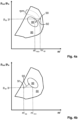
- the current operational point 90 of the compressor 50 lies at a higher charge air mass flow, m' op , than the maximum charge air mass flow, m' max , of the reference area 88 at the compressor pressure ratio, p op : p, of the current operational point 90.
- the operational point of the compressor 50 is moved towards, and/or into the reference area 88, as indicated by the arrow 92.
- the reference area 88 may represent an optimal operational range of the compressor 50.
- the compressor 50 will operate in a more optimal portion of the compressor map 86 than the previous current operational point 90.
- flexible adaptation of operation of the compressor 50 is achieved.
- the control system 46 may comprise a charge air pressure sensor 81, and one of the at least two parameters may be the current charge air pressure or the current compressor pressure ratio.
- the current charge air pressure or the current compressor pressure ratio may be determined utilising the charge air pressure sensor 81.
- the current compressor pressure ratio may be used directly for determining the current operational point 90 of the compressor 50.
- the current charge air pressure may be utilised for calculating and/or for determining an approximation of the current compressor pressure ratio, as discussed above, which then in turn may be used for determining the current operational point 90 of the compressor 50. In the latter case the control system 46 may utilise information about ambient air pressure in order to calculate the compressor pressure ratio.
- control system 46 may comprise at least two of a turbocharger rotational speed sensor 78, a charge air mass flow sensor 80, an engine rotational speed sensor 82, and a charge air temperature sensor 84.
- these sensors 78, 80, 82, 84 may be utilised for determining the current charge air mass flow of the operational point 90 of the compressor 50 as discussed above with respect to the current turbocharger rotational speed, the current charge air mass flow, the current charge air pressure, and the current compressor pressure ratio.
- a turbine map may be utilised for determining the rotational speed of the turbocharger 14.
- the turbine map may show the turbine pressure ratio and mass flow through the turbine.
- control system 46 may be configured to:
- the control system 46 is further configured to, in response to the at least two parameters indicating that the current operational point 91 of the compressor 50 is outside the reference area 88 at the lower charge air mass flow than the minimum charge air mass flow of the reference area 88 at the compressor pressure ratio of the current operational point 91:
- the current operational point 91 of the compressor 50 lies at a lower charge air mass flow, m' op , than the minimum charge air mass flow, m' min , of the reference area 88 at the compressor pressure ratio, p op : p, of the current operational point 91.
- the operational point of the compressor 50 is moved towards, and/or into the reference area 88, as indicated by the arrow 93.
- the reference area 88 may represent an optimal operational range of the compressor 50.
- the compressor 50 will operate in a more optimal portion of the compressor map 86 than the previous current operational point 91.
- flexible adaptation of operation of the compressor 50 is achieved.
- control system 46 may be further configured to:
- control system 46 may be configured:
- the entailing negative overlap due to the change in timing between the open exhaust and intake valves 10, 12 may reduce flow of exhaust gas to the turbine 52 and thus, reduce the rotational speed of the turbocharger 14.
- the turbocharger rotational speed and/or cylinder pressure of the cylinder arrangement 6 may be reduced in order to protect the ICE 4 against being overloaded.
- a turbocharger rotational speed sensor 78 may be utilised for determining the rotational speed of the turbocharger 14.
- the turbocharger rotational speed may be determined from the compressor map 86.
- these embodiments may be utilised in embodiments of the ICE 4 wherein the ICE comprises a decompression brake 94, see Fig. 2 .
- turbocharger rotational speed and/or cylinder pressure of the cylinder arrangement 6 may be reduced in order to protect the ICE 4 against being overloaded during compression braking.
- the compression brake 94 also known as compression release engine brake, is a well-known device for releasing compressed gas from the combustion chamber 16 in order to slow down a vehicle.
- control system 46 may be configured to:
- control system 46 may be configured to:
- control system 46 in response to the current lambda value being below the target lambda value or lambda value range, the control system 46 may be configured to:
- Fig. 4c illustrates with reference to the turbine map 86 how the current lambda value of the ICE 4 may be adjusted utilising the above discussed changing of the timing of the camshafts 10, 12.
- lambda, ⁇ , of an ICE i.e. the air-fuel equivalence ratio is the ratio of actual/current air-fuel ratio to stoichiometric air-fuel ratio.
- the ICE 4 is operated at a target lambda value, or within a target lambda value range. If ambient air conditions differ from those at which the ICE 4 is set, the current lambda value will differ from the target lambda value, or the target lambda value range. In the example illustrated in Fig. 4c , the target lambda value is 2.0. However, if ambient air pressure is high and/or ambient air temperature is low, the current lambda value may be e.g. 2.2. Accordingly, by reducing an overlap between the open exhaust and intake valves 10, 12, or by creating a negative overlap, the lambda value 2.0 of the ICE 4 may be reached again, by reducing airflow through the cylinder arrangement 6.
- This sequence of lambda value changes is shown with dash-dotted arrows in Fig. 4c .
- the current lambda value may be e.g. 1.8.
- the lambda value 2.0 of the ICE 4 may be reached again, by increasing airflow through the cylinder arrangement 6.
- This sequence of lambda value changes is shown with a broken line arrows in Fig. 4c .
- Compressor maps 86 are utilised in Figs. 4a - 4d in order to illustrate different aspects of the control system 46 of the ICE 4 and of the method 100, see Fig. 6 .
- a compressor map 86 defines the operational area of the compressor 50 of a turbocharger 14. as a field in a coordinate system having axes expressing charge air mass flow, m', and compressor pressure ratio, p out : p in .
- Turbocharger rotational speeds are represented by curved lines in the compressor map 86.
- Fig. 4a illustrates change of timing of the camshafts 10, 12 to reduce an overlap or create a negative overlap when a current operational point 90 of the compressor 50 lies at a high charge air mass flow, m' op .
- Fig. 4b illustrates change of timing of the camshafts 10, 12 to increase an overlap when a current operational point 91 of the compressor 50 lies at a low charge air mass flow, m' op .
- Fig. 4c illustrates adjustment of a current lambda value of the ICE 4 towards a target lambda value by changing the timing of the camshafts 10, 12.
- Fig. 4d two examples similar to those of Figs. 4a and 4b are illustrated.
- the two examples relate to the changing of the timing of the camshafts 10, 12 in case of the turbine 50 choking or surging.
- the reference area 88 corresponds to the compressor map 86.
- the current operational point 90 lies outside the reference area 88 at a high charge air mass flow, i.e. when the turbine 50 is choking.
- the operational point 90 is moved back into the operational range of the turbine 50, i.e.
- the operational point 90 is moved into the reference area 88 and the compressor map 86.
- the current operational point 91 lies outside the reference area 88 at a low charge air mass flow, i.e. when the turbine 50 is surging.
- the operational point 91 is moved back into the operational range of the turbine 50, i.e. the operational point 91 is moved into the reference area 88 and the compressor map 86.
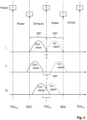
- Fig. 5 illustrates diagrams over the ICE 4 of Fig. 2 , and control thereof in accordance with the discussion above related to Figs. 3 - 4d .
- Fig. 5 illustrates the four strokes of a piston 26 and the movements of the exhaust valve 20 (full line) and of the intake valve 22 (dash-dotted line) during operation of the ICE 4.
- the crankshaft 8 of the ICE 4 rotates 720° as the four strokes of the piston 26 are performed. For each stroke, the crankshaft 8 rotates 180 degrees CA as indicated in Fig. 5 .
- the rotational angle ⁇ of rotation of the crankshaft 8 in the transition between the exhaust stroke of the piston 26 and the intake stroke of the piston 26 may be at least 5 degrees. That is, the negative overlap may be at least 5 degrees CA. According to some embodiments, the angle ⁇ of rotation of the crankshaft in the transition between the exhaust stroke of the piston and the intake stroke of the piston is within a range of 5 - 160 degrees CA. That is, the negative overlap may be within a range of 5 - 160 degrees CA.
- the length of the open period of each of the exhaust and intake valves 20, 22 remains the same. That is, the change of the timing of the exhaust and intake camshafts 10, 12 does not affect the length in degrees CA that the exhaust and intake valves 20, 22 remain open. Put differently, the valve opening times of the exhaust and intake valves 20, 22 are of constant duration before and after the change of timing of the camshafts 10, 12.
- the change of the timing of the exhaust and intake valves 20, 22 is substantially symmetrical about TDCge. That is, the absolute value of degrees CA of the change of timing is substantially the same for the exhaust valve 20 as for the intake valve 22.
- the change of the timing of the exhaust camshaft 10 to advance closing of the exhaust valve 20 in advancing CA degrees may be of an equal magnitude as the change of the timing of the intake camshaft 12 to delay opening of the intake valve 22 in delay CA degrees.
- the change of the timing of the exhaust camshaft 10 to advance closing of the exhaust valve 20 in advancing CA degrees may be of a magnitude differing within a range of maximum +/- 10 CA degrees from the change of the timing of the intake camshaft 12 to delay opening of the intake valve 22 in delay CA degrees.
- the change of the timing of the exhaust camshaft 10 to delay closing of the exhaust valve 20 in delay CA degrees may be of an equal magnitude as the change of the timing of the intake camshaft 12 to advance opening of the intake valve 22 in advancing CA degrees.
- the change of the timing of the exhaust camshaft 10 to delay closing of the exhaust valve 20 in delay CA degrees may be of a magnitude differing within a range of maximum +/- 10 CA degrees from the change of the timing of the intake camshaft 12 to advance opening of the intake valve 22 in advancing CA degrees
- the change of timing of each of the camshafts 10, 12 may be variable over a range of degrees CA.
- the transition of the operational point of the compressor 50 of the turbocharger 14 towards the reference area 88 and/or towards the target lambda value may be finely tuned.
- Fig. 6 illustrates embodiments of a method 100 of controlling timings of an exhaust camshaft and an intake camshaft of a four-stroke ICE.
- the ICE may be an ICE 4 comprising a control system 46 as discussed above in connection with Figs. 1-5 . Accordingly, in the following reference is also made to Figs. 1-5 .
- the method 100 comprises steps of:
- the method 100 may comprise steps of:
- the method 100 may comprise steps of:
- the method 100 may comprise steps of:
- the method 100 may comprise a step of:
- a computer program comprising instructions which, when the program is executed by a computer, causes the computer to carry out a method 100 according to any one of aspects and/or embodiments discussed herein.
- the method 100 of controlling timings of an exhaust camshaft 10 and an intake camshaft 12 of a four-stroke ICE 4 may be implemented by programmed instructions.
- These programmed instructions are typically constituted by a computer program, which, when it is executed in a computer or calculation unit 62, ensures that the computer or calculation unit 62 carries out the desired control, such as the method steps 102 - 124 according to the invention.
- the computer program is usually part of a computer-readable storage medium which comprises a suitable digital storage medium on which the computer program is stored.
- Fig. 7 illustrates embodiments of a computer-readable storage medium 99 comprising instructions which, when executed by a computer or calculation unit 62, cause the computer or calculation unit 62 to carry out the steps of the method 100 according to any one of aspects and/or embodiments discussed herein.
- the computer-readable storage medium 99 may be provided for instance in the form of a data carrier carrying computer program code for performing at least some of the steps 102 - 124 according to some embodiments when being loaded into the one or more calculation units 62.
- the data carrier may be, e.g. a ROM (read-only memory), a PROM (programable read-only memory), an EPROM (erasable PROM), a flash memory, an EEPROM (electrically erasable PROM), a hard disc, a CD ROM disc, a memory stick, an optical storage device, a magnetic storage device or any other appropriate medium such as a disk or tape that may hold machine readable data in a non-transitory manner.
- the computer-readable storage medium may furthermore be provided as computer program code on a server and may be downloaded to the calculation unit 62 remotely, e.g., over an Internet or an intranet connection, or via other wired or wireless communication systems.
- the computer-readable storage medium 99 shown in Fig. 7 is a nonlimiting example in the form of a USB memory stick.
Landscapes
- Engineering & Computer Science (AREA)
- Mechanical Engineering (AREA)
- General Engineering & Computer Science (AREA)
- Chemical & Material Sciences (AREA)
- Combustion & Propulsion (AREA)
- Output Control And Ontrol Of Special Type Engine (AREA)
- Supercharger (AREA)
Claims (18)
- Viertakt-Verbrennungsmotor (4) mit wenigstens einer Zylinderanordnung (6), einer Kurbelwelle (8), einer Auslassnockenwelle (10), einer Einlassnockenwelle (12), einem Turbolader (14) und einem Steuersystem (46), wobeidie Zylinderanordnung (6) einen Brennraum (12), eine Zylinderbohrung (18), einen Kolben (20), der dazu eingerichtet ist, sich in der Zylinderbohrung (18) hin- und herzubewegen, und mit der Kurbelwelle (8) verbunden ist, ein Auslassventil (20) und ein Einlassventil (22) umfasst, wobeidie Auslassnockenwelle (10) zum Steuern des Öffnens und Schließens des Auslassventils (20) eingerichtet ist und die Einlassnockenwelle (12) zum Steuern des Öffnens und Schließens des Einlassventils (22) eingerichtet ist, wobeider Turbolader (14) einen Verdichter (50) und eine Turbine (52) umfasst, wobei die Turbine (52) in einem sich von dem Auslassventil (20) erstreckenden Abgasströmungsweg (56) angeordnet ist, wobeieine Taktung der Auslassnockenwelle (10) und eine Taktung der Einlassnockenwelle (12) durch das Steuersystem (46) steuerbar sind, wobeidas Steuersystem (46) eingerichtet ist zum:- Speichern eines Verdichterkennfelds (86), das sich auf den Verdichter (50) des Turboladers (14) bezieht,- Speichern eines Referenzbereichs (88) in dem Verdichterkennfeld (86)- Bestimmen von wenigstens zwei der folgenden Parameter: aktuelle Turboladerdrehzahl, aktueller Ladeluftmassenstrom und entweder aktueller Ladeluftdruck oder aktuelles Verdichterdruckverhältnisund als Reaktion darauf, dass die wenigstens zwei Parameter anzeigen, dass ein aktueller Betriebspunkt (90) des Verdichters (50) außerhalb des Referenzbereichs (88) bei einem höheren Ladeluftmassenstrom (m'op) als einem maximalen Ladeluftmassenstrom (m'max) des Referenzbereichs (88) bei einem Verdichterdruckverhältnis (Pop :p) des aktuellen Betriebspunkts (90) liegt,- Ändern der Taktung der Auslassnockenwelle (10), um das Schließen des Auslassventils (20) vorzuverlegen, und- Ändern der Taktung der Einlassnockenwelle (12), um das Öffnen des Einlassventils (22) zu verzögern.
- Viertakt-Verbrennungsmotor (4) nach Anspruch 1, wobei das Steuersystem (46) einen Ladeluftdrucksensor (81) umfasst und wobei einer der wenigstens zwei Parameter der aktuelle Ladeluftdruck oder das aktuelle Verdichterdruckverhältnis ist.
- Viertakt-Verbrennungsmotor (4) nach Anspruch 1 oder 2, wobei das Steuersystem (46) einen oder mehrere der folgenden Sensoren umfasst: Turboladerdrehzahlsensor (78), Ladeluftmassenstromsensor (80), Motordrehzahlsensor (82) und Ladelufttemperatursensor (84).
- Viertakt-Verbrennungsmotor (4) nach einem der vorangehenden Ansprüche, wobei das Steuersystem (46) als Reaktion darauf, dass die wenigstens zwei Parameter anzeigen, dass ein aktueller Betriebspunkt (91) des Verdichters (50) außerhalb des Referenzbereichs (88) bei einem geringeren Ladeluftmassenstrom als einem minimalen Ladeluftmassenstrom des Referenzbereichs (88) bei einem Verdichterdruckverhältnis des aktuellen Betriebspunkts liegt, eingerichtet ist zum:- Ändern der Taktung der Auslassnockenwelle (10), um das Schließen des Auslassventils (20) zu verzögern, und- Ändern der Taktung der Einlassnockenwelle (12), um das Öffnen des Einlassventils (22) vorzuverlegen.
- Viertakt-Verbrennungsmotor (4) nach einem der vorangehenden Ansprüche, wobei sich der gesamte Abgasströmungsweg (56) durch die Turbine (52) erstreckt.
- Viertakt-Verbrennungsmotor (4) nach einem der vorangehenden Ansprüche, wobei das Steuersystem (46) eingerichtet ist zum:- Bestimmen einer aktuellen Turboladerdrehzahl und/oder eines Zylinderdrucks der Zylinderanordnung (6)
und als Reaktion darauf, dass die aktuelle Turboladerdrehzahl über einem Schwellenwert für die maximale Drehzahl liegt und/oder der Zylinderdruck über einem maximalen Zylinderdruck liegt,- Ändern der Taktung der Auslassnockenwelle (10), um das Schließen des Auslassventils (20) vorzuverlegen, und- Ändern der Taktung der Einlassnockenwelle (12), um das Öffnen des Einlassventils (22) zu verzögern. - Viertakt-Verbrennungsmotor (4) nach Anspruch 6, wobei der Verbrennungsmotor eine Dekompressionsbremse (94) umfasst.
- Viertakt-Verbrennungsmotor (4) nach einem der vorangehenden Ansprüche, wobei das Steuersystem (46) eingerichtet ist zum:- Speichern eines Lambdasollwerts oder eines Lambdawertbereichs- Bestimmen eines aktuellen Lambdawerts
und als Reaktion darauf dass der aktuelle Lambdawert über dem Lambdasollwert oder dem Lambdawertbereich liegt,- Ändern der Taktung der Auslassnockenwelle (10), um das Schließen des Auslassventils (20) vorzuverlegen, und- Ändern der Taktung der Einlassnockenwelle (12), um das Öffnen des Einlassventils (22) zu verzögern. - Viertakt-Verbrennungsmotor (4) nach Anspruch 8, wobei das Steuersystem (46) als Reaktion darauf, dass der aktuelle Lambdawert unter dem Lambdasollwert oder dem Lambdawertbereich liegt, eingerichtet ist zum:- Ändern der Taktung der Auslassnockenwelle (10), um das Schließen des Auslassventils (20) zu verzögern, und- Ändern der Taktung der Einlassnockenwelle (12), um das Öffnen des Einlassventils (22) vorzuverlegen.
- Viertakt-Verbrennungsmotor (4) nach Anspruch 1 oder 6 oder 8, wobei die Änderung der Taktung der Auslassnockenwelle (10), um das Schließen des Auslassventils (20) in vorrückenden KW-Graden vorzuverlegen, in der gleichen Größenordnung liegt oder sich in einem Bereich von maximal +/- 10 KW-Graden von der Änderung der Taktung der Einlassnockenwelle (12), um das Öffnen des Einlassventils (22) in verzögernden KW-Graden zu verzögern, unterscheidet.
- Fahrzeug (2) mit einem Viertakt-Verbrennungsmotor (4) nach einem der Ansprüche 1-10.
- Verfahren (100) zum Steuern der Taktungen einer Auslassnockenwelle (10) und einer Einlassnockenwelle (12) eines Viertakt-Verbrennungsmotors (4), der wenigstens eine Zylinderanordnung (6), eine Kurbelwelle (8), die Auslassnockenwelle (10), die Einlassnockenwelle (12), einen Turbolader (14) und ein Steuersystem (46) umfasst, wobeidie Zylinderanordnung (6) einen Brennraum (12), eine Zylinderbohrung (18), einen Kolben (20), der dazu eingerichtet ist, sich in der Zylinderbohrung (18) hin- und herzubewegen, und mit der Kurbelwelle (8) verbunden ist, ein Auslassventil (20) und ein Einlassventil (22) umfasst, wobeidie Auslassnockenwelle (10) zum Steuern des Öffnens und Schließens des Auslassventils (20) eingerichtet ist und die Einlassnockenwelle (12) zum Steuern des Öffnens und Schließens des Einlassventils (22) eingerichtet ist, wobeider Turbolader (14) einen Verdichter (50) und eine Turbine (52) umfasst, wobei die Turbine (52) in einem sich von dem Auslassventil (20) erstreckenden Abgasströmungsweg (56) angeordnet ist, wobeidas Steuersystem (46) zum Speichern eines Verdichterkennfelds (86), das sich auf den Verdichter (50) des Turboladers (14) bezieht, und zum Speichern eines Referenzbereichs (88) in dem Verdichterkennfeld (86) eingerichtet ist und wobeidas Verfahren (100) folgende Schritte umfasst:- Bestimmen (102) von wenigstens zwei der folgenden Parameter: aktuelle Turboladerdrehzahl, aktueller Ladeluftmassenstrom und entweder aktueller Ladeluftdruck oder aktuelles Verdichterdruckverhältnis- Feststellen (104), ob die wenigstens zwei Parameter anzeigen, dass ein aktueller Betriebspunkt des Verdichters (50) außerhalb des Referenzbereichs (88) bei einem höheren Ladeluftmassenstrom als einem maximalen Ladeluftmassenstrom des Referenzbereichs (88) bei einem Verdichterdruckverhältnis des aktuellen Betriebspunkts liegt, und als Reaktion darauf Ausführen folgender Schritte:- Ändern (106) der Taktung der Auslassnockenwelle (10), um das Schließen des Auslassventils (20) vorzuverlegen, und- Ändern (108) der Taktung der Einlassnockenwelle (12), um das Öffnen des Einlassventils (22) zu verzögern.
- Verfahren (100) nach Anspruch 12, das folgende Schritte umfasst:- Feststellen (110), ob die wenigstens zwei Parameter anzeigen, dass ein aktueller Betriebspunkt des Verdichters (50) außerhalb des Referenzbereichs (88) bei einem geringeren Ladeluftmassenstrom als einem minimalen Ladeluftmassenstrom des Referenzbereichs (88) bei einem Verdichterdruckverhältnis des aktuellen Betriebspunkts liegt, und als Reaktion darauf Ausführen folgender Schritte:- Ändern (112) der Taktung der Auslassnockenwelle (10), um das Schließen des Auslassventils (20) zu verzögern, und- Ändern (114) der Taktung der Einlassnockenwelle (12), um das Öffnen des Einlassventils (22) vorzuverlegen.
- Verfahren (100) nach Anspruch 12 oder 13, das folgende Schritte umfasst:- Bestimmen (116) einer aktuellen Turboladerdrehzahl und/oder eines Zylinderdrucks der Zylinderanordnung (6)- Bestimmen (118), ob die aktuelle Turboladerdrehzahl über einem Schwellenwert für die maximale Drehzahl liegt und/oder der Zylinderdruck über einem maximalen Zylinderdruck liegt, und als Reaktion darauf Ausführen folgender Schritte:- Ändern (106) der Taktung der Auslassnockenwelle (10), um das Schließen des Auslassventils (20) vorzuverlegen, und- Ändern (108) der Taktung der Einlassnockenwelle (12), um das Öffnen des Einlassventils (22) zu verzögern.
- Verfahren (100) nach einem der Ansprüche 12-14, wobei das Steuersystem (46) zum Steuern eines Lambdasollwerts oder eines Lambdawertbereichs eingerichtet ist und wobei das Verfahren (100) folgende Schritte umfasst:- Bestimmen (120) eines aktuellen Lambdawerts- Bestimmen (122), ob der aktuelle Lambdawert über dem Lambdasollwert oder dem Lambdawertbereich liegt, und als Reaktion darauf Ausführen folgender Schritte:- Ändern (106) der Taktung der Auslassnockenwelle (10), um das Schließen des Auslassventils (20) vorzuverlegen, und- Ändern (108) der Taktung der Einlassnockenwelle (12), um das Öffnen des Einlassventils (22) zu verzögern.
- Verfahren (100) nach Anspruch 15, das folgende Schritte umfasst:- Bestimmen (124), ob der aktuelle Lambdawert unter dem Lambdasollwert oder dem Lambdawertbereich liegt, und als Reaktion darauf- Ändern (112) der Taktung der Auslassnockenwelle (10), um das Schließen des Auslassventils (20) zu verzögern, und- Ändern (114) der Taktung der Einlassnockenwelle (12), um das Öffnen des Einlassventils (22) vorzuverlegen.
- Computerprogramm mit Befehlen, die, wenn das Programm von einem Steuersystem ausgeführt wird, das Steuersystem dazu veranlassen, das Verfahren (100) nach einem der Ansprüche 12-16 auszuführen.
- Computerlesbares Speichermedium (99) mit Befehlen, die, wenn sie von einem Steuersystem ausgeführt werden, das Steuersystem dazu veranlassen, das Verfahren (100) nach einem der Ansprüche 12-16 auszuführen.
Applications Claiming Priority (2)
| Application Number | Priority Date | Filing Date | Title |
|---|---|---|---|
| SE1951201A SE543456C2 (en) | 2019-10-23 | 2019-10-23 | Four-Stroke Internal Combustion Engine and Method of Controlling Timings of an Exhaust Camshaft and an Intake Camshaft |
| PCT/SE2020/051025 WO2021080499A1 (en) | 2019-10-23 | 2020-10-22 | Four-stroke internal combustion engine and method of controlling timings of an exhaust camshaft and an intake camshaft |
Publications (3)
| Publication Number | Publication Date |
|---|---|
| EP4048878A1 EP4048878A1 (de) | 2022-08-31 |
| EP4048878A4 EP4048878A4 (de) | 2023-12-06 |
| EP4048878B1 true EP4048878B1 (de) | 2025-01-22 |
Family
ID=74571289
Family Applications (1)
| Application Number | Title | Priority Date | Filing Date |
|---|---|---|---|
| EP20879502.1A Active EP4048878B1 (de) | 2019-10-23 | 2020-10-22 | Viertakt-verbrennungsmotor und verfahren zur steuerung der taktungen einer auslassnockenwelle und einer einlassnockenwelle |
Country Status (6)
| Country | Link |
|---|---|
| US (1) | US11686259B2 (de) |
| EP (1) | EP4048878B1 (de) |
| CN (1) | CN114466968B (de) |
| BR (1) | BR112022006053A2 (de) |
| SE (1) | SE543456C2 (de) |
| WO (1) | WO2021080499A1 (de) |
Families Citing this family (1)
| Publication number | Priority date | Publication date | Assignee | Title |
|---|---|---|---|---|
| SE545437C2 (en) * | 2020-12-11 | 2023-09-12 | Scania Cv Ab | Controlling Valve Actuation of an Internal Combustion Engine |
Family Cites Families (26)
| Publication number | Priority date | Publication date | Assignee | Title |
|---|---|---|---|---|
| US6105555A (en) * | 1999-04-01 | 2000-08-22 | Cummins Engine Company, Inc. | Turbocharged internal combustion engine with system and method for enhancing turbocharger power |
| SE522080C2 (sv) | 1999-12-13 | 2004-01-13 | Volvo Car Corp | Fyrtakts förbränningsmotor med variabla kamtider |
| JP2002206446A (ja) * | 2001-01-10 | 2002-07-26 | Hitachi Ltd | 内燃機関及び内燃機関の燃料噴射制御装置 |
| JP4517515B2 (ja) * | 2001-02-14 | 2010-08-04 | マツダ株式会社 | 自動車用4サイクルエンジン |
| SE518687C2 (sv) | 2001-03-30 | 2002-11-05 | Saab Automobile | Sätt att styra laddtrycket vid turboladdad förbränningsmotor samt dylik motor |
| FI124107B (fi) | 2006-06-30 | 2014-03-14 | Wärtsilä Finland Oy | Mäntämoottorin kaasunvaihtoventtiilin ohjausjärjestely ja menetelmä mäntämoottorin kaasunvaihtoventtiilin ohjaamiseksi |
| US7762068B2 (en) * | 2006-08-10 | 2010-07-27 | Toyota Jidosha Kabushiki Kaisha | Control apparatus for internal combustion engine with supercharger |
| JP4512617B2 (ja) * | 2007-06-26 | 2010-07-28 | 日立オートモティブシステムズ株式会社 | 内燃機関の制御装置および方法 |
| US7801665B2 (en) * | 2007-07-13 | 2010-09-21 | Ford Global Technologies, Llc | Controlling cylinder mixture and turbocharger operation |
| JP4623064B2 (ja) * | 2007-08-13 | 2011-02-02 | トヨタ自動車株式会社 | 過給機付き内燃機関の制御装置 |
| US8141357B2 (en) * | 2007-10-12 | 2012-03-27 | Mazda Motor Corporation | Supercharger for an engine |
| JP4900333B2 (ja) * | 2007-11-13 | 2012-03-21 | トヨタ自動車株式会社 | 内燃機関の制御装置 |
| JP4592770B2 (ja) * | 2008-02-27 | 2010-12-08 | エムエーエヌ・ディーゼル・アンド・ターボ・フィリアル・アフ・エムエーエヌ・ディーゼル・アンド・ターボ・エスイー・ティスクランド | カムシャフトを備える大型2サイクルディーゼルエンジンの可変バルブタイミング |
| KR101657322B1 (ko) * | 2008-11-20 | 2016-09-13 | 바르실라 핀랜드 오이 | 피스톤 엔진의 과급기 속도 제어 방법 및 과급된 피스톤 엔진의 제어 시스템 |
| CN103195593B (zh) * | 2012-01-06 | 2017-03-22 | 伍德沃德公司 | 使用分流排气系统和方法的发动机 |
| WO2013109249A1 (en) * | 2012-01-17 | 2013-07-25 | International Engine Intellectual Property Company, Llc | Coordinating variable valve actuation and turbocharger operation in an internal combustion engine |
| US8714123B2 (en) | 2012-01-18 | 2014-05-06 | Ford Global Technologies, Llc | Oil pressure modification for variable cam timing |
| SE1250143A1 (sv) | 2012-02-20 | 2013-02-15 | Scania Cv Ab | Kamföljare för en ventillyftanordning i en förbränningsmotor |
| DK177695B1 (en) * | 2012-11-16 | 2014-03-17 | Man Diesel & Turbo Deutschland | A large slow running turbocharged two-stoke uniflow internal combustion engine with crosshead and a cam driven exhaust valve actuation system |
| DE102013000495B3 (de) * | 2013-01-15 | 2014-03-13 | Voith Patent Gmbh | Antriebsstrang, insbesondere für ein Kraftfahrzeug |
| DE102015104100B4 (de) * | 2014-03-26 | 2019-12-24 | GM Global Technology Operations LLC (n. d. Ges. d. Staates Delaware) | Kraftmaschinensteuerverfahren für Getriebehochschaltungen |
| US9453435B2 (en) * | 2014-10-07 | 2016-09-27 | GM Global Technology Operations LLC | Control of internal combustion engine with two-stage turbocharging |
| JP6427435B2 (ja) * | 2015-02-09 | 2018-11-21 | 本田技研工業株式会社 | 圧力式アクチュエータ |
| CN107532526B (zh) * | 2015-11-20 | 2020-11-10 | 三菱重工发动机和增压器株式会社 | 增压系统的控制装置 |
| SE540733C2 (sv) | 2016-06-15 | 2018-10-23 | Scania Cv Ab | Förbränningsmotor och fordon innefattande en hydraulisk fasförskjutningsanordning |
| US10494991B2 (en) * | 2017-07-18 | 2019-12-03 | Ford Global Technologies, Llc | Transient compensation for variable geometry compressor |
-
2019
- 2019-10-23 SE SE1951201A patent/SE543456C2/en unknown
-
2020
- 2020-10-22 CN CN202080068522.9A patent/CN114466968B/zh active Active
- 2020-10-22 EP EP20879502.1A patent/EP4048878B1/de active Active
- 2020-10-22 WO PCT/SE2020/051025 patent/WO2021080499A1/en not_active Ceased
- 2020-10-22 BR BR112022006053A patent/BR112022006053A2/pt unknown
- 2020-10-22 US US17/769,366 patent/US11686259B2/en active Active
Also Published As
| Publication number | Publication date |
|---|---|
| CN114466968A (zh) | 2022-05-10 |
| SE1951201A1 (en) | 2021-02-23 |
| SE543456C2 (en) | 2021-02-23 |
| BR112022006053A2 (pt) | 2022-07-12 |
| US11686259B2 (en) | 2023-06-27 |
| EP4048878A4 (de) | 2023-12-06 |
| EP4048878A1 (de) | 2022-08-31 |
| US20230049122A1 (en) | 2023-02-16 |
| WO2021080499A1 (en) | 2021-04-29 |
| CN114466968B (zh) | 2024-04-23 |
Similar Documents
| Publication | Publication Date | Title |
|---|---|---|
| CN102297015A (zh) | 涡轮增压器控制系统 | |
| CN110360014B (zh) | 用于内燃发动机的控制设备 | |
| US10669951B2 (en) | Four-stroke internal combustion engine thereto related vehicle and method | |
| US7891185B2 (en) | Turbo-generator control with variable valve actuation | |
| JP2009002283A (ja) | 内燃機関の制御装置 | |
| CN111788378B (zh) | 内燃机及其控制方法 | |
| GB2507061A (en) | Method of two-stage turbocharger matching for supporting cylinder deactivation. | |
| US9163559B2 (en) | Internal combustion engine and a method of operation of an internal combustion engine | |
| JP2009019611A (ja) | 過給機付き内燃機関の制御装置 | |
| EP4048878B1 (de) | Viertakt-verbrennungsmotor und verfahren zur steuerung der taktungen einer auslassnockenwelle und einer einlassnockenwelle | |
| SE541888C2 (en) | Four-Stroke Internal Combustion Engine and thereto related Vehicle and Method | |
| US10767588B2 (en) | Control apparatus for engine | |
| CN109595085B (zh) | 内燃机的控制装置 | |
| JP6914591B2 (ja) | 内燃機関の制御装置 | |
| GB2524111A (en) | Method of operating an exhaust valve of an internal combustion engine | |
| US12146446B2 (en) | Controlling valve actuation of an internal combustion engine to prevent compressor surge | |
| US11111842B2 (en) | Method for charge pressure control of an internal combustion engine | |
| JP2011179472A (ja) | 内燃機関の制御装置 | |
| WO2020162810A1 (en) | Method of controlling a combustion engine, combustion engine, and related devices | |
| JP2010019085A (ja) | エンジンの吸気制御装置 |
Legal Events
| Date | Code | Title | Description |
|---|---|---|---|
| STAA | Information on the status of an ep patent application or granted ep patent |
Free format text: STATUS: THE INTERNATIONAL PUBLICATION HAS BEEN MADE |
|
| PUAI | Public reference made under article 153(3) epc to a published international application that has entered the european phase |
Free format text: ORIGINAL CODE: 0009012 |
|
| STAA | Information on the status of an ep patent application or granted ep patent |
Free format text: STATUS: REQUEST FOR EXAMINATION WAS MADE |
|
| 17P | Request for examination filed |
Effective date: 20220523 |
|
| AK | Designated contracting states |
Kind code of ref document: A1 Designated state(s): AL AT BE BG CH CY CZ DE DK EE ES FI FR GB GR HR HU IE IS IT LI LT LU LV MC MK MT NL NO PL PT RO RS SE SI SK SM TR |
|
| DAV | Request for validation of the european patent (deleted) | ||
| DAX | Request for extension of the european patent (deleted) | ||
| P01 | Opt-out of the competence of the unified patent court (upc) registered |
Effective date: 20230518 |
|
| REG | Reference to a national code |
Ref country code: DE Ref legal event code: R079 Free format text: PREVIOUS MAIN CLASS: F02B0037120000 Ipc: F02D0041000000 Ref country code: DE Ref legal event code: R079 Ref document number: 602020045328 Country of ref document: DE Free format text: PREVIOUS MAIN CLASS: F02B0037120000 Ipc: F02D0041000000 |
|
| A4 | Supplementary search report drawn up and despatched |
Effective date: 20231107 |
|
| RIC1 | Information provided on ipc code assigned before grant |
Ipc: F02B 37/12 20060101ALN20231031BHEP Ipc: F02D 13/04 20060101ALN20231031BHEP Ipc: F02D 41/24 20060101ALI20231031BHEP Ipc: F02D 13/02 20060101ALI20231031BHEP Ipc: F02D 41/00 20060101AFI20231031BHEP |
|
| GRAP | Despatch of communication of intention to grant a patent |
Free format text: ORIGINAL CODE: EPIDOSNIGR1 |
|
| STAA | Information on the status of an ep patent application or granted ep patent |
Free format text: STATUS: GRANT OF PATENT IS INTENDED |
|
| INTG | Intention to grant announced |
Effective date: 20240909 |
|
| RIC1 | Information provided on ipc code assigned before grant |
Ipc: F02B 37/12 20060101ALN20240902BHEP Ipc: F02D 13/04 20060101ALN20240902BHEP Ipc: F02D 41/24 20060101ALI20240902BHEP Ipc: F02D 13/02 20060101ALI20240902BHEP Ipc: F02D 41/00 20060101AFI20240902BHEP |
|
| GRAS | Grant fee paid |
Free format text: ORIGINAL CODE: EPIDOSNIGR3 |
|
| GRAA | (expected) grant |
Free format text: ORIGINAL CODE: 0009210 |
|
| STAA | Information on the status of an ep patent application or granted ep patent |
Free format text: STATUS: THE PATENT HAS BEEN GRANTED |
|
| AK | Designated contracting states |
Kind code of ref document: B1 Designated state(s): AL AT BE BG CH CY CZ DE DK EE ES FI FR GB GR HR HU IE IS IT LI LT LU LV MC MK MT NL NO PL PT RO RS SE SI SK SM TR |
|
| REG | Reference to a national code |
Ref country code: GB Ref legal event code: FG4D |
|
| REG | Reference to a national code |
Ref country code: CH Ref legal event code: EP |
|
| REG | Reference to a national code |
Ref country code: IE Ref legal event code: FG4D |
|
| REG | Reference to a national code |
Ref country code: DE Ref legal event code: R096 Ref document number: 602020045328 Country of ref document: DE |
|
| REG | Reference to a national code |
Ref country code: NL Ref legal event code: MP Effective date: 20250122 |
|
| PG25 | Lapsed in a contracting state [announced via postgrant information from national office to epo] |
Ref country code: NL Free format text: LAPSE BECAUSE OF FAILURE TO SUBMIT A TRANSLATION OF THE DESCRIPTION OR TO PAY THE FEE WITHIN THE PRESCRIBED TIME-LIMIT Effective date: 20250122 |
|
| PG25 | Lapsed in a contracting state [announced via postgrant information from national office to epo] |
Ref country code: RS Free format text: LAPSE BECAUSE OF FAILURE TO SUBMIT A TRANSLATION OF THE DESCRIPTION OR TO PAY THE FEE WITHIN THE PRESCRIBED TIME-LIMIT Effective date: 20250422 |
|
| PG25 | Lapsed in a contracting state [announced via postgrant information from national office to epo] |
Ref country code: FI Free format text: LAPSE BECAUSE OF FAILURE TO SUBMIT A TRANSLATION OF THE DESCRIPTION OR TO PAY THE FEE WITHIN THE PRESCRIBED TIME-LIMIT Effective date: 20250122 |
|
| PG25 | Lapsed in a contracting state [announced via postgrant information from national office to epo] |
Ref country code: PL Free format text: LAPSE BECAUSE OF FAILURE TO SUBMIT A TRANSLATION OF THE DESCRIPTION OR TO PAY THE FEE WITHIN THE PRESCRIBED TIME-LIMIT Effective date: 20250122 |
|
| PG25 | Lapsed in a contracting state [announced via postgrant information from national office to epo] |
Ref country code: ES Free format text: LAPSE BECAUSE OF FAILURE TO SUBMIT A TRANSLATION OF THE DESCRIPTION OR TO PAY THE FEE WITHIN THE PRESCRIBED TIME-LIMIT Effective date: 20250122 |
|
| REG | Reference to a national code |
Ref country code: LT Ref legal event code: MG9D |
|
| PG25 | Lapsed in a contracting state [announced via postgrant information from national office to epo] |
Ref country code: IS Free format text: LAPSE BECAUSE OF FAILURE TO SUBMIT A TRANSLATION OF THE DESCRIPTION OR TO PAY THE FEE WITHIN THE PRESCRIBED TIME-LIMIT Effective date: 20250522 Ref country code: NO Free format text: LAPSE BECAUSE OF FAILURE TO SUBMIT A TRANSLATION OF THE DESCRIPTION OR TO PAY THE FEE WITHIN THE PRESCRIBED TIME-LIMIT Effective date: 20250422 |
|
| REG | Reference to a national code |
Ref country code: AT Ref legal event code: MK05 Ref document number: 1761632 Country of ref document: AT Kind code of ref document: T Effective date: 20250122 |
|
| PG25 | Lapsed in a contracting state [announced via postgrant information from national office to epo] |
Ref country code: HR Free format text: LAPSE BECAUSE OF FAILURE TO SUBMIT A TRANSLATION OF THE DESCRIPTION OR TO PAY THE FEE WITHIN THE PRESCRIBED TIME-LIMIT Effective date: 20250122 |
|
| PG25 | Lapsed in a contracting state [announced via postgrant information from national office to epo] |
Ref country code: LV Free format text: LAPSE BECAUSE OF FAILURE TO SUBMIT A TRANSLATION OF THE DESCRIPTION OR TO PAY THE FEE WITHIN THE PRESCRIBED TIME-LIMIT Effective date: 20250122 Ref country code: PT Free format text: LAPSE BECAUSE OF FAILURE TO SUBMIT A TRANSLATION OF THE DESCRIPTION OR TO PAY THE FEE WITHIN THE PRESCRIBED TIME-LIMIT Effective date: 20250522 |
|
| PG25 | Lapsed in a contracting state [announced via postgrant information from national office to epo] |
Ref country code: GR Free format text: LAPSE BECAUSE OF FAILURE TO SUBMIT A TRANSLATION OF THE DESCRIPTION OR TO PAY THE FEE WITHIN THE PRESCRIBED TIME-LIMIT Effective date: 20250423 Ref country code: BG Free format text: LAPSE BECAUSE OF FAILURE TO SUBMIT A TRANSLATION OF THE DESCRIPTION OR TO PAY THE FEE WITHIN THE PRESCRIBED TIME-LIMIT Effective date: 20250122 |
|
| PG25 | Lapsed in a contracting state [announced via postgrant information from national office to epo] |
Ref country code: AT Free format text: LAPSE BECAUSE OF FAILURE TO SUBMIT A TRANSLATION OF THE DESCRIPTION OR TO PAY THE FEE WITHIN THE PRESCRIBED TIME-LIMIT Effective date: 20250122 |
|
| PG25 | Lapsed in a contracting state [announced via postgrant information from national office to epo] |
Ref country code: SE Free format text: LAPSE BECAUSE OF FAILURE TO SUBMIT A TRANSLATION OF THE DESCRIPTION OR TO PAY THE FEE WITHIN THE PRESCRIBED TIME-LIMIT Effective date: 20250122 |
|
| PG25 | Lapsed in a contracting state [announced via postgrant information from national office to epo] |
Ref country code: SM Free format text: LAPSE BECAUSE OF FAILURE TO SUBMIT A TRANSLATION OF THE DESCRIPTION OR TO PAY THE FEE WITHIN THE PRESCRIBED TIME-LIMIT Effective date: 20250122 |
|
| PG25 | Lapsed in a contracting state [announced via postgrant information from national office to epo] |
Ref country code: DK Free format text: LAPSE BECAUSE OF FAILURE TO SUBMIT A TRANSLATION OF THE DESCRIPTION OR TO PAY THE FEE WITHIN THE PRESCRIBED TIME-LIMIT Effective date: 20250122 |
|
| PG25 | Lapsed in a contracting state [announced via postgrant information from national office to epo] |
Ref country code: IT Free format text: LAPSE BECAUSE OF FAILURE TO SUBMIT A TRANSLATION OF THE DESCRIPTION OR TO PAY THE FEE WITHIN THE PRESCRIBED TIME-LIMIT Effective date: 20250122 |
|
| PGFP | Annual fee paid to national office [announced via postgrant information from national office to epo] |
Ref country code: BE Payment date: 20250917 Year of fee payment: 6 Ref country code: GB Payment date: 20250828 Year of fee payment: 6 |
|
| PGFP | Annual fee paid to national office [announced via postgrant information from national office to epo] |
Ref country code: FR Payment date: 20250908 Year of fee payment: 6 |
|
| PG25 | Lapsed in a contracting state [announced via postgrant information from national office to epo] |
Ref country code: CZ Free format text: LAPSE BECAUSE OF FAILURE TO SUBMIT A TRANSLATION OF THE DESCRIPTION OR TO PAY THE FEE WITHIN THE PRESCRIBED TIME-LIMIT Effective date: 20250122 Ref country code: EE Free format text: LAPSE BECAUSE OF FAILURE TO SUBMIT A TRANSLATION OF THE DESCRIPTION OR TO PAY THE FEE WITHIN THE PRESCRIBED TIME-LIMIT Effective date: 20250122 |
|
| REG | Reference to a national code |
Ref country code: DE Ref legal event code: R097 Ref document number: 602020045328 Country of ref document: DE |
|
| PG25 | Lapsed in a contracting state [announced via postgrant information from national office to epo] |
Ref country code: RO Free format text: LAPSE BECAUSE OF FAILURE TO SUBMIT A TRANSLATION OF THE DESCRIPTION OR TO PAY THE FEE WITHIN THE PRESCRIBED TIME-LIMIT Effective date: 20250122 |
|
| PG25 | Lapsed in a contracting state [announced via postgrant information from national office to epo] |
Ref country code: SK Free format text: LAPSE BECAUSE OF FAILURE TO SUBMIT A TRANSLATION OF THE DESCRIPTION OR TO PAY THE FEE WITHIN THE PRESCRIBED TIME-LIMIT Effective date: 20250122 |
|
| PLBE | No opposition filed within time limit |
Free format text: ORIGINAL CODE: 0009261 |
|
| STAA | Information on the status of an ep patent application or granted ep patent |
Free format text: STATUS: NO OPPOSITION FILED WITHIN TIME LIMIT |
|
| 26N | No opposition filed |
Effective date: 20251023 |
|
| PGFP | Annual fee paid to national office [announced via postgrant information from national office to epo] |
Ref country code: DE Payment date: 20250902 Year of fee payment: 6 |