EP4048892B1 - Packungsdichtung für einen kolbenverdichter und verfahren zum betrieb desselben - Google Patents
Packungsdichtung für einen kolbenverdichter und verfahren zum betrieb desselben Download PDFInfo
- Publication number
- EP4048892B1 EP4048892B1 EP20790173.7A EP20790173A EP4048892B1 EP 4048892 B1 EP4048892 B1 EP 4048892B1 EP 20790173 A EP20790173 A EP 20790173A EP 4048892 B1 EP4048892 B1 EP 4048892B1
- Authority
- EP
- European Patent Office
- Prior art keywords
- piston
- packing seal
- magnetic bearing
- piston rod
- longitudinal axis
- Prior art date
- Legal status (The legal status is an assumption and is not a legal conclusion. Google has not performed a legal analysis and makes no representation as to the accuracy of the status listed.)
- Active
Links
Images


Classifications
-
- F—MECHANICAL ENGINEERING; LIGHTING; HEATING; WEAPONS; BLASTING
- F04—POSITIVE - DISPLACEMENT MACHINES FOR LIQUIDS; PUMPS FOR LIQUIDS OR ELASTIC FLUIDS
- F04B—POSITIVE-DISPLACEMENT MACHINES FOR LIQUIDS; PUMPS
- F04B35/00—Piston pumps specially adapted for elastic fluids and characterised by the driving means to their working members, or by combination with, or adaptation to, specific driving engines or motors, not otherwise provided for
- F04B35/01—Piston pumps specially adapted for elastic fluids and characterised by the driving means to their working members, or by combination with, or adaptation to, specific driving engines or motors, not otherwise provided for the means being mechanical
-
- F—MECHANICAL ENGINEERING; LIGHTING; HEATING; WEAPONS; BLASTING
- F04—POSITIVE - DISPLACEMENT MACHINES FOR LIQUIDS; PUMPS FOR LIQUIDS OR ELASTIC FLUIDS
- F04B—POSITIVE-DISPLACEMENT MACHINES FOR LIQUIDS; PUMPS
- F04B39/00—Component parts, details, or accessories, of pumps or pumping systems specially adapted for elastic fluids, not otherwise provided for in, or of interest apart from, groups F04B25/00 - F04B37/00
- F04B39/0005—Component parts, details, or accessories, of pumps or pumping systems specially adapted for elastic fluids, not otherwise provided for in, or of interest apart from, groups F04B25/00 - F04B37/00 adaptations of pistons
- F04B39/0022—Component parts, details, or accessories, of pumps or pumping systems specially adapted for elastic fluids, not otherwise provided for in, or of interest apart from, groups F04B25/00 - F04B37/00 adaptations of pistons piston rods
-
- F—MECHANICAL ENGINEERING; LIGHTING; HEATING; WEAPONS; BLASTING
- F04—POSITIVE - DISPLACEMENT MACHINES FOR LIQUIDS; PUMPS FOR LIQUIDS OR ELASTIC FLUIDS
- F04B—POSITIVE-DISPLACEMENT MACHINES FOR LIQUIDS; PUMPS
- F04B39/00—Component parts, details, or accessories, of pumps or pumping systems specially adapted for elastic fluids, not otherwise provided for in, or of interest apart from, groups F04B25/00 - F04B37/00
- F04B39/0094—Component parts, details, or accessories, of pumps or pumping systems specially adapted for elastic fluids, not otherwise provided for in, or of interest apart from, groups F04B25/00 - F04B37/00 crankshaft
-
- F—MECHANICAL ENGINEERING; LIGHTING; HEATING; WEAPONS; BLASTING
- F04—POSITIVE - DISPLACEMENT MACHINES FOR LIQUIDS; PUMPS FOR LIQUIDS OR ELASTIC FLUIDS
- F04B—POSITIVE-DISPLACEMENT MACHINES FOR LIQUIDS; PUMPS
- F04B39/00—Component parts, details, or accessories, of pumps or pumping systems specially adapted for elastic fluids, not otherwise provided for in, or of interest apart from, groups F04B25/00 - F04B37/00
- F04B39/04—Measures to avoid lubricant contaminating the pumped fluid
- F04B39/041—Measures to avoid lubricant contaminating the pumped fluid sealing for a reciprocating rod
- F04B39/042—Measures to avoid lubricant contaminating the pumped fluid sealing for a reciprocating rod sealing being provided on the piston
-
- F—MECHANICAL ENGINEERING; LIGHTING; HEATING; WEAPONS; BLASTING
- F04—POSITIVE - DISPLACEMENT MACHINES FOR LIQUIDS; PUMPS FOR LIQUIDS OR ELASTIC FLUIDS
- F04B—POSITIVE-DISPLACEMENT MACHINES FOR LIQUIDS; PUMPS
- F04B39/00—Component parts, details, or accessories, of pumps or pumping systems specially adapted for elastic fluids, not otherwise provided for in, or of interest apart from, groups F04B25/00 - F04B37/00
- F04B39/12—Casings; Cylinders; Cylinder heads; Fluid connections
- F04B39/121—Casings
-
- F—MECHANICAL ENGINEERING; LIGHTING; HEATING; WEAPONS; BLASTING
- F04—POSITIVE - DISPLACEMENT MACHINES FOR LIQUIDS; PUMPS FOR LIQUIDS OR ELASTIC FLUIDS
- F04B—POSITIVE-DISPLACEMENT MACHINES FOR LIQUIDS; PUMPS
- F04B39/00—Component parts, details, or accessories, of pumps or pumping systems specially adapted for elastic fluids, not otherwise provided for in, or of interest apart from, groups F04B25/00 - F04B37/00
- F04B39/12—Casings; Cylinders; Cylinder heads; Fluid connections
- F04B39/122—Cylinder block
-
- F—MECHANICAL ENGINEERING; LIGHTING; HEATING; WEAPONS; BLASTING
- F04—POSITIVE - DISPLACEMENT MACHINES FOR LIQUIDS; PUMPS FOR LIQUIDS OR ELASTIC FLUIDS
- F04B—POSITIVE-DISPLACEMENT MACHINES FOR LIQUIDS; PUMPS
- F04B49/00—Control, e.g. of pump delivery, or pump pressure of, or safety measures for, machines, pumps, or pumping installations, not otherwise provided for, or of interest apart from, groups F04B1/00 - F04B47/00
- F04B49/06—Control using electricity
-
- F—MECHANICAL ENGINEERING; LIGHTING; HEATING; WEAPONS; BLASTING
- F04—POSITIVE - DISPLACEMENT MACHINES FOR LIQUIDS; PUMPS FOR LIQUIDS OR ELASTIC FLUIDS
- F04B—POSITIVE-DISPLACEMENT MACHINES FOR LIQUIDS; PUMPS
- F04B53/00—Component parts, details or accessories not provided for in, or of interest apart from, groups F04B1/00 - F04B23/00 or F04B39/00 - F04B47/00
- F04B53/08—Cooling; Heating; Preventing freezing
-
- F—MECHANICAL ENGINEERING; LIGHTING; HEATING; WEAPONS; BLASTING
- F04—POSITIVE - DISPLACEMENT MACHINES FOR LIQUIDS; PUMPS FOR LIQUIDS OR ELASTIC FLUIDS
- F04B—POSITIVE-DISPLACEMENT MACHINES FOR LIQUIDS; PUMPS
- F04B9/00—Piston machines or pumps characterised by the driving or driven means to or from their working members
- F04B9/02—Piston machines or pumps characterised by the driving or driven means to or from their working members the means being mechanical
- F04B9/04—Piston machines or pumps characterised by the driving or driven means to or from their working members the means being mechanical the means being cams, eccentrics or pin-and-slot mechanisms
- F04B9/045—Piston machines or pumps characterised by the driving or driven means to or from their working members the means being mechanical the means being cams, eccentrics or pin-and-slot mechanisms the means being eccentrics
Definitions
- the invention relates to a packing seal for a piston compressor and a method for operating the same.
- the document US 1526909 discloses a piston compressor with a packing seal.
- This piston compressor is subject to relatively high wear, the piston compressor can only be operated at a relatively low speed, and replacing the packing seal is relatively complex.
- the document WO2014/ 139565A1 discloses a piston compressor with a horizontally extending cylinder in which a piston is arranged that can move back and forth in a horizontal direction.
- This piston compressor has the disadvantage that the guide rings and/or sealing rings arranged on the piston are subject to relatively high wear and that the piston compressor can only be operated at a relatively low speed.
- the document DE3805670A1 discloses a piston compressor with a vertically extending cylinder, whereby the piston can be designed as a labyrinth piston or as a piston provided with captured piston rings.
- the document US4889039 discloses another piston compressor with a packing, wherein the piston is designed as a labyrinth piston, and wherein the packing has a seal with a plurality of grooves which seal the piston rod according to the labyrinth principle.
- the piston rod and the piston are held as centered as possible by two magnetic bearings in order to ensure contact-free movement of the piston and piston rod.
- the document WO2006/042866 discloses a piston rod seal comprising a sealing ring, the Sealing surface can be moved radially to the piston rod by means of an actuator.
- the object of the invention is to provide a more advantageous packing seal for a piston compressor and a more advantageous operating method of a piston compressor comprising the packing seal.
- the piston compressor preferably comprises a piston and a piston rod which are arranged to be movable in the horizontal or vertical direction.
- a packing seal for a piston compressor comprising a longitudinal axis and, in the direction of the longitudinal axis (L), a fastening part (12c) and a cylindrical part (12p), one following the other, wherein a magnetic bearing and a seal are arranged in the cylindrical part (12p), wherein the magnetic bearing (13) comprises at least one controllable electromagnet (13f), characterized in that the seal is designed as a chamber ring (12a) with a sealing ring (12b) arranged therein, that the sealing ring (12b) can be displaced radially to the longitudinal axis (L) in the chamber ring (12a), and that in the cylindrical part (12p), in the direction of the longitudinal axis (L), following the fastening part (12c), the magnetic bearing (13) and the chamber ring (12a) are arranged one following the other.
- a method for operating a piston compressor (1) comprising a piston (3) which is moved back and forth in the direction of a longitudinal axis (L) within a cylinder (7), wherein the piston (3) is driven via a piston rod (16), and comprising a packing seal (12) with a controllable magnetic bearing (13) and a seal, wherein the piston rod (16) runs through the packing seal (12), and wherein a controllable magnetic force (F m ) acting at least perpendicular to the longitudinal axis (L) is exerted on the piston rod (16) via the controllable magnetic bearing (13), characterized in that the piston rod (16) is sealed in the seal by a chamber ring (12a) with a sealing ring (12b) arranged therein, that the piston rod (16) is sealed between the piston (3) and the magnetic bearing (13), that the piston rod (16) is radially guided to the longitudinal axis by the magnetic bearing (13) (L) is moved and thereby the contact force of the piston supported on the inner surface of the cylinder
- the packing seal is arranged in a piston compressor for compressing a gas, comprising a cylinder, a piston, a piston rod, the packing seal, a crosshead, a magnetic bearing and a drive, wherein the piston is arranged to be movable in a longitudinal direction within the cylinder, wherein the piston is connected to the crosshead via the piston rod, wherein the packing seal is arranged between the piston and the crosshead, through which the piston rod runs, wherein the crosshead is driven by the drive, wherein the magnetic bearing is arranged between the piston and the crosshead, and wherein the magnetic bearing can cause a magnetic force on the piston rod at least perpendicular to the longitudinal direction, wherein a sensor is arranged to detect a state variable of the piston compressor, wherein the magnetic bearing is designed as a controllable magnetic bearing, and wherein a Control device which controls the magnetic force exerted by the magnetic bearing on the piston rod depending on the state variable.
- the cylinder particularly preferably runs essentially in a horizontal direction.
- the packing seal is arranged in a piston compressor for compressing a gas, comprising a cylinder running essentially in a horizontal direction and comprising a piston, a piston rod, the packing seal, a crosshead and a drive, wherein the piston is arranged to be movable in a longitudinal direction within the cylinder, wherein the piston is connected to the crosshead via a piston rod, wherein a packing seal is arranged between the piston and the crosshead, through which the piston rod runs, and wherein the crosshead is driven by the drive, wherein a controllable magnetic bearing is also arranged between the piston and the crosshead, wherein the magnetic bearing can cause a magnetic force on the piston rod at least perpendicular to the longitudinal direction, and wherein a control device controls the magnetic force caused by the magnetic bearing on the piston rod.
- the packing seal is used in a method for operating a piston compressor, wherein the piston compressor comprises a piston which is moved back and forth in a longitudinal direction within a cylinder, wherein the piston is driven via a piston rod, and wherein a magnetic force acting at least perpendicular to the longitudinal direction is exerted on the piston rod, wherein a state variable of the piston compressor is detected, wherein the magnetic force is controlled depending on the state variable, and wherein a force, preferably a relief force, is thereby exerted on the piston via the piston rod.
- the longitudinal direction runs essentially in a horizontal direction.
- the packing seal is used in a method for operating a piston compressor, wherein the piston compressor comprises a piston which is moved back and forth in a longitudinal direction within a cylinder, wherein the longitudinal direction runs essentially in a horizontal direction, wherein the piston is driven via a piston rod, wherein a controllable magnetic force acting at least perpendicular to the longitudinal direction is exerted on the piston rod and thereby a relief force is caused on the piston via the piston rod, wherein the magnetic force is controlled as a function of a state variable.
- the piston compressor comprises a piston which is moved back and forth in a longitudinal direction within a cylinder, wherein the longitudinal direction runs essentially in a horizontal direction, wherein the piston is driven via a piston rod, wherein a controllable magnetic force acting at least perpendicular to the longitudinal direction is exerted on the piston rod and thereby a relief force is caused on the piston via the piston rod, wherein the magnetic force is controlled as a function of a state variable.
- the packing seal according to the invention for a piston compressor comprises a controllable magnetic bearing which is arranged between a piston and a crosshead of the piston compressor, wherein a piston rod connects the piston to the crosshead, wherein the piston rod runs through the magnetic bearing, and wherein the magnetic bearing exerts a controllable, magnetic attraction force on the piston rod at least perpendicular to the direction of travel of the piston rod.
- the packing seal according to the invention also preferably comprises at least one sensor which can be connected to a control device, wherein the control device is designed to supply electromagnets arranged in the controllable magnetic bearing with electrical current or electrical power, wherein the control device modulates or changes the supplied current or the supplied power depending on the value measured by the sensor in order to influence the position of the piston with respect to the cylinder, so that the piston has an advantageous position within the cylinder at least temporarily.
- the controllable magnetic bearing is preferably designed as a radial bearing, comprising a plurality of electromagnets distributed in the circumferential direction and controllable by the control device.
- the magnetic bearing could also be designed in such a way that the magnetic force only acts in one direction or in one dimension, for example by two controllable electromagnets are arranged opposite or symmetrically with respect to the piston rod, so that a magnetic force exerted by these electromagnets on the piston rod only acts in one dimension.
- the piston compressor comprises at least one cylinder and a piston arranged to move back and forth within the cylinder, wherein the cylinder interior and thus also the movement of the piston in a preferred embodiment runs in a horizontal direction or essentially in a horizontal direction, wherein such a piston compressor is also referred to as a horizontal piston compressor.
- Piston compressor is preferably understood here to mean a reciprocating piston compressor.
- the magnetic bearing exerts a controllable, magnetic attraction force on the piston rod at least perpendicular to the direction of travel of the piston rod, and thus preferably causes a vertically upward force on the piston rod, preferably in a direction opposite to gravity.
- the piston which is movable in the horizontal direction, comprises a so-called guide ring, which rests on the inner surface of the cylinder.
- the attractive force exerted by the magnetic bearing on the piston rod at least in the vertical direction and/or the repulsive force exerted on the piston rod results in the bearing force of a piston supported on the inner surface of the cylinder being reduced, or in the piston or the guide ring no longer touching the inner surface of the cylinder, so that the piston or the guide ring of the piston either only rests on the inner surface of the cylinder with reduced bearing force, and particularly advantageously moves back and forth within the cylinder without touching the inner surface of the cylinder.
- the use of the magnetic bearing has the advantage that the bearing force of the guide ring on the inner surface and thus the wear of the guide ring is reduced, so that the guide ring has a longer service life or a higher service life before it needs to be replaced.
- the piston compressor can be operated at a higher speed if desired, whereby preferably no increased wear or heating occurs.
- the packing seal according to the invention is particularly advantageously used in combination with a piston which is designed as a labyrinth piston, such a labyrinth piston, as is known per se, having a labyrinth structure on its surface which serves to seal between the piston and the inner surface of the cylinder.
- the attractive force exerted by the magnetic bearing on the piston rod is preferably controlled in such a way that the piston moving back and forth does not touch the inner surface of the cylinder along the entire stroke, in that the magnet layer preferably strives to keep the piston in a central position with respect to the interior of the cylinder.
- the packing seal according to the invention is, however, also suitable for piston compressors comprising pistons with piston rings and optionally additionally having guide rings.
- the piston compressor described here can, for example, have only a single piston with piston rod and cylinder, or preferably a plurality of pistons, piston rods and cylinders, in which case each piston rod preferably runs through a packing seal according to the invention.
- the cylinder interior and thus also the movement of the piston runs in a vertical direction or essentially in a vertical direction.
- the magnetic bearing exerts a controllable magnetic attraction force on the piston rod at least perpendicular to the direction of travel of the piston rod, and thus causes a force on the piston rod and the piston that runs radially or essentially radially to the piston rod.
- the attraction force exerted by the magnetic bearing on the piston rod at least in a radial direction and/or the repulsion force exerted on the piston rod results in the contact force of a inner surface of the cylinder, and in particular a one-sided contact force, is reduced, or that the piston or its piston ring, and in particular a piston designed as a labyrinth piston, no longer touches the inner surface of the cylinder, so that the piston or the piston ring either only rests on the inner surface of the cylinder with reduced contact force, and particularly advantageously the labyrinth piston moves back and forth within the cylinder without touching the inner surface of the cylinder.
- the use of the magnetic bearing has the advantage that wear on the piston ring is reduced, so that the piston compressor has a longer service life or a longer lifespan before it needs to be serviced. There is also the option of operating the piston compressor at a higher speed. If the piston compressor has a labyrinth piston, the use of the magnetic bearing has the advantage that contact between the labyrinth piston and the inner surface of the cylinder can be avoided even better, since any eccentric arrangement of the labyrinth piston with respect to the interior of the cylinder can be at least partially corrected with the help of the magnetic bearing, and the piston is preferably centered in the interior of the cylinder with respect to its longitudinal axis so that no mutual contact occurs.
- the use of the magnetic bearing has the additional advantage that the piston compressor can also be operated safely with a reduced gap width between the labyrinth piston outer surface and the inner surface of the cylinder without mutual contact occurring. This reduced gap width increases the efficiency of the piston compressor and reduces the loss during compression.
- the piston compressor has at least one piston and one cylinder, and preferably a plurality of pistons and cylinders, which are preferably arranged on a common frame and which are preferably driven by a common crankshaft.
- a piston compressor is on a ship arranged, with the cylinder, the cylinder interior and thus also the movement of the piston running in a vertical direction or essentially in a vertical direction in calm seas.
- Rough or stormy seas mean that the ship performs an increasing rolling or pitching movement as the wave height increases, which means that the entire piston compressor and thus in particular also the longitudinal direction of the piston rod has a course that varies depending on the wave state as a function of time and deviates from the vertical by an angle beta.
- the angle beta, and preferably the angle beta as a function of time is measured as an additional state variable.
- a multi-stage piston compressor is used to compress exhaust gas accumulating in a liquid gas tank to a pressure of 200 to 500 bar in order to use the compressed gas to supply fuel to a gas engine or a diesel engine on the ship.
- a piston compressor arranged on a ship is preferably operated in such a way that the force exerted by the magnetic bearing on the piston rod at least in the radial direction is controlled as a function of the state variable and the additional state variable in such a way that the contact force of a piston ring resting on the inner surface of the cylinder, and in particular a one-sided contact force, is reduced, or that the piston or its piston ring, and in particular a piston designed as a labyrinth piston, no longer touches the inner surface of the cylinder, so that on a ship, even in waves, it is guaranteed that the piston(s) or the piston ring(s) of the piston compressor either only rests on the inner surface of the cylinder with reduced contact force, and particularly advantageously the labyrinth
- the use of the magnetic bearing has the advantage that wear on the piston ring is reduced even in waves, or that contact with the labyrinth structure of the Labyrinth piston with the inner wall of the cylinder is avoided, especially when the gap width between the outer diameter of the piston and the inner wall of the cylinder is small, so that a piston compressor arranged on a ship has a longer service life or a longer lifespan before it needs to be serviced.
- the magnetic bearing is preferably controlled in such a way that the magnetic bearing exerts a damping effect on the piston rod radially to the longitudinal axis of the piston rod in order to dampen movement of the piston rod and the piston in the direction radial to the longitudinal axis, for example in order to reduce the maximum amplitude of resonance vibrations or other transverse vibrations of the piston, for example caused by waves.
- the wave motion or the measured and derived additional state variable represents a relatively slow process compared to the speed of the piston compressor, and the period of a wave motion of the water is slow by a factor of 10 to 1000 compared to the period of one revolution of the piston compressor, it is possible to predict a short-term change in the additional state variable and to incorporate this value into the control of the magnetic bearing by controlling the magnetic bearing with a predictive control which predicts the movement of the piston compressor to be expected due to the wave motion, for example for a point in time that can be in the range of 1 to 50 seconds, and controls the magnetic bearing accordingly, so that when influencing or controlling the position of the piston rod or piston, the expected movement of the piston compressor caused by the wave motion is also taken into account.
- the packing seal according to the invention in combination with the piston compressor also has the advantage that it can operate at a higher speed or with a higher average Piston speed can be operated because the piston or the guide ring either no longer touches the inner cylinder wall at all, or only rests against the inner cylinder wall with reduced contact force.
- Such operation with a higher number of revolutions is particularly advantageous in the case of a piston compressor with a so-called dry-running piston, i.e. a labyrinth piston, or a piston with self-lubricating sealing rings, i.e. a piston whose piston or sealing rings are not oil-lubricated, which is also referred to as an unlubricated piston.
- the controllable magnetic bearing can either be used as a load-bearing bearing, by which the piston is held without touching the inner surface of the cylinder, or it can be used as a relief bearing, by which the force exerted by the piston on the inner surface of the cylinder is reduced, in which case the piston touches the inner wall.
- the controllable magnetic bearing can also take on a centering function in the case of an essentially vertical piston, by which the piston is centered and preferably held without touching the inner surface of the cylinder.
- the magnetic bearing is arranged at a predetermined location in the horizontal piston compressor, whereas the position of the center of gravity of the piston changes constantly due to the back and forth movement during operation, so that the length of the lever arm formed by the piston rod between the magnetic bearing and the center of gravity of the piston changes constantly during operation.
- a control device provided for supplying power to the magnetic bearing is therefore advantageously designed in such a way that the magnetic force exerted by the magnetic bearing on the piston rod is controlled to change depending on the position of the piston or depending on the length of the lever arm mentioned above.
- at least one force acting in the vertical direction is exerted on the piston rod.
- the magnetic bearing is particularly advantageously designed as a radial bearing, which, perpendicular to the longitudinal direction of the piston rod, can exert a controllable force on the piston rod in two dimensions, preferably a force in the vertical direction and a force in the horizontal direction.
- a radial bearing is controlled in such a way that the piston does not touch the inner surface of the cylinder during operation in any of its possible positions, neither a lower, an upper or a lateral inner surface of the cylinder.
- the magnetic bearing is preferably controlled as a function of a measured state variable, in particular when the piston is not to touch the inner surface of the cylinder during operation, the state variable comprising at least one of the following variables: displacement path of the piston in the cylinder, displacement path of the piston rod in the direction of travel of the piston rod, displacement path of the piston rod perpendicular to the direction of travel of the piston rod, and angle of rotation of the drive shaft.
- the distance of the piston rod with respect to the magnetic bearing is suitable as the state variable, at least in the vertical direction, and in particular the gap width in the magnetic bearing between the piston rod and the magnetic bearing.
- the sensor for detecting the state variable is advantageously designed to detect at least one of the following variables: angle of inclination ⁇ of the longitudinal direction relative to the vertical, angle of inclination ⁇ as a function of time, gap width between the inner cylinder surface and the piston side surface, location of a mutual contact point between the piston and the cylinder.
- the packing seal is preferably used in combination with the piston compressor, whereby the piston rod runs through this packing seal or its sealing rings in order to seal the cylinder interior against the outside, whereby the packing seal also has the magnetic bearing in addition to the sealing rings.
- the packing seal according to the invention is Particularly advantageously designed as a replacement part, so that the packing seal can be removed as a whole, i.e. as a unit, from the piston compressor and reinstalled or replaced with a new packing seal.
- the packing seal according to the invention has the same or essentially the same external dimensions as previously known packing seals without magnetic bearings, so that the packing seal according to the invention comprising the magnetic bearing can be used for installation in existing piston compressors in order to retrofit them and improve their quality.
- the packing seal according to the invention also comprises cooling channels.
- these cooling channels are connected to a cooling circuit in order to cool the magnetic bearing and/or the packing seal.
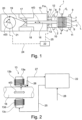
- Fig. 1 shows a piston compressor 1 for compressing a gas, comprising a cylinder 2 running in a horizontal direction and comprising a piston 3 that is movable within the cylinder 2 in the direction of the cylinder 2 or in the longitudinal direction L.
- the piston compressor 1 also comprises a piston rod 16, a packing seal 12, a magnetic bearing 13, a crosshead 17 with a linear guide 18, a push rod 19 and a drive, for example a crank 20 with a drive shaft 21.
- the piston 3 is double-acting in the embodiment shown and comprises sealing or piston rings 4 and a guide ring 5, wherein the piston 3 divides the interior of the cylinder 2 into a first interior 6 and a second interior 7, wherein these two interiors each have an inlet valve 8, 9 and an outlet valve 10, 11.
- the cylinder 2 is connected to a housing 15 via an intermediate piece 14, wherein the packing seal 12 and the magnetic bearing 13 are also arranged in the intermediate piece.
- the magnetic bearing 13 exerts a magnetic force F m on the piston rod 16 at least in the vertical direction.
- a control device 22 detects a state variable Z of the piston compressor 1 via a signal line 24 and a sensor (not shown), for example the displacement path s(t) of the piston in the cylinder 7 as a function of time, the displacement path s(t) of the piston rod 16 and/or a rotation angle ⁇ (t) of the drive shaft 21 as a function of time.
- the control device 22 controls the current in the electromagnet of the magnetic bearing 13 and thereby the forces generated by the magnets. magnetic force exerted on the piston rod 16 via a signal line 25.
- control device 22 can be operated in a control mode in which a state variable Z is measured and the magnetic force F m is changed as a function of the state variable Z.
- feedback can be dispensed with.
- Figure 3 shows an example of such a control mode in which the course of a curve K1 is specified, the curve K1 specifying the relationship of the state variable Z, in the present case the angle of rotation ⁇ of the drive shaft 21, and the magnetic force F m to be generated as a function of the angle of rotation ⁇ .
- the angle of rotation ⁇ is measured with a sensor (not shown) and fed to the control device 22 via the signal line 24.
- the curve K1 can be specified, for example, based on empirical values.
- This embodiment is particularly advantageous if, as in Figure 1 shown, a piston 3 having a guide ring 5 is used, wherein the guide ring 5 rests on the inner surface of the cylinder 2, and wherein the magnetic force F m serves to reduce the contact force of the guide ring 5 on the inner surface of the cylinder 2, in order to thereby reduce in particular wear of the guide ring 5.
- the in Figure 3 The curve K1 shown only shows the course of the magnetic force Fm as a function of the crankshaft angle ⁇ between 0° and 180°.
- the force F m starting from the value at 180°, runs in the opposite direction to the value of F m at the angle of 0°, which value is identical to the value at the angle of 360°.
- a measuring device for example a sensor 26, is provided to measure the position of the piston rod 16 and/or the piston 3 at least in the vertical direction.
- Figure 2 shows an embodiment which measures the position of the piston rod 16 in the vertical direction.
- the sensor 26 is arranged close to the magnetic bearing 13 or even within the magnetic bearing 13, wherein the sensor 26 advantageously measures the distance D between an upper coil core 13a of the magnetic bearing 13 and the surface of the piston rod 16.
- the magnetic bearing 13 advantageously comprises at least an upper coil core 13a with coil 13b and a lower coil core 13c with coil 13d.
- the magnetic bearing 13 can, as in Figure 6 shown, can also be designed as a radial magnetic bearing, with a plurality of electromagnets 13f distributed in the circumferential direction, wherein their coils 13b, 13d can preferably be controlled individually, so that the direction of the magnetic force F m acting on the piston rod 16 can be determined by appropriate control of the coils 13b, 13d.
- the control device 22 is given a setpoint value for the distance D via the setpoint specification 28, whereby the control device 22 controls the coils 13b, 13d with current via the signal line 25 in such a way that the piston rod 16 has a substantially constant, constant distance D with respect to the upper coil core 13a, regardless of the stroke s(t) or the crankshaft angle ⁇ (t).
- the piston rod 16 acts as a magnetic armature of the two coil cores 13a, 13b.
- the magnetic bearing 13 can cause both an upward force and a downward magnetic attraction force on the piston rod 16, so that the position of the piston rod 16 relative to the magnetic bearing 13 can be controlled particularly precisely.
- the piston compressor 1 is thus advantageously operated in such a way that a controllable magnetic force F m is exerted on the piston rod 16, so that a force F m acting at least in the vertical direction, or a relief force F h , is exerted on the piston 3 via the piston rod 16, which counteracts the force of gravity F, wherein the magnetic force F m is controlled or changed depending on a state variable Z such as the distance D, the stroke s(t) or the angle of rotation ⁇ (t).
- a state variable Z such as the distance D, the stroke s(t) or the angle of rotation ⁇ (t).
- Figure 7 shows another embodiment of a piston compressor, which in comparison to the one in Figure 1
- the piston compressor 1 shown is designed with a cylinder 2 or cylinder interior running essentially in a vertical direction, with a piston rod 16 running essentially in a vertical direction, and with a piston 3 movable in this direction.
- Figure 7 a packing seal 12 in which the radial bearing 13 is integrated.
- the radial bearing 13 is supplied with power via the line 25 and is connected to a coolant circuit via the line 27.
- the piston compressor 1 is arranged on a ship with a heeling angle, which is why the cylinder 2 and the piston rod 16 have an inclination angle ⁇ with respect to the vertical V.
- the piston compressor 1 is preferably arranged in the ship in such a way that the cylinder 2 and the piston rod 16 run exactly in the vertical direction or at least approximately in the vertical direction when the sea is absolutely calm.
- the piston compressor 1 could of course also be arranged on land, and the cylinder 2 and the piston rod 16 preferably run exactly in the vertical direction or at least approximately in the vertical direction.
- the angle of inclination ⁇ with respect to the vertical V is measured with a sensor 26 (not shown), wherein the angle of inclination ⁇ is preferably measured as a function of time t.
- the magnetic bearing 13 is controlled via the control device 22 in such a way that a magnetic force F m is exerted on the piston rod 16 and that the piston rod 16 transmits a relief force Fn to the piston 3, so that, due to the acting relief force F h , the position of the piston 3 within the cylinder 2 is influenced, if possible.
- At least one of the following variables is suitable: angle of inclination ⁇ of the cylinder with respect to the vertical V, gap width between the inner cylinder surface and the piston side surface, location of a mutual contact point between the piston and the cylinder.
- the magnetic bearing 13 is advantageously controlled in such a way that the mutual distance between the piston rod 16 and the magnetic bearing 13 and/or the distance between the inner surface of the cylinder and the side surface of the piston, perpendicular to the longitudinal direction L, is kept constant or essentially constant.
- the piston 3 is preferably held in the cylinder 7 without touching the wall.
- the angle of inclination ⁇ (t) between the vertical V and the longitudinal direction L is preferably also measured as a function of time t as the state variable Z. It is particularly advantageous for the magnetic force F m to be controlled by means of a predictive control in a piston compressor arranged on a ship.
- the state variable Z advantageously includes the angle of inclination ⁇ (t) as a function of time t, so that the state variable Z is dependent on time t.
- the state variable Z comprises, in addition to the inclination angle ⁇ (t) as a function of time t, at least one further state variable mentioned herein, so that such a resulting state variable consists of a combination of at least two of the above-mentioned mentioned state variables.
- a resulting state variable could include the state variable Z of the movement of the piston rod perpendicular to the longitudinal direction L, and be combined with the state variable Z of the inclination angle ⁇ (t) as a function of time t, so that with the help of the predictive control and the knowledge of the state variable Z of the inclination angle ⁇ (t) as a function of time t, the expected movement of the piston rod perpendicular to the longitudinal direction L caused by the inclination angle ⁇ (t) at time t + ⁇ t can be calculated in advance, and the magnetic bearing 12 can be controlled with this predictive state variable Zv(t + ⁇ t).
- a predictive state variable Zv(t + ⁇ t) is calculated from the state variable Z(t) as a function of the inclination angle ⁇ (t) for a future time t+ ⁇ t, and the magnetic force F m is controlled at the current time t as a function of the predictive state variable Zv(t + ⁇ t).
- the piston compressor according to the invention comprising the controllable magnetic bearing is particularly advantageously used in combination with a transport ship which is used for transports over the sea.
- the one in Figure 4 The longitudinal section shown shows a known packing seal 12, comprising a plurality of chamber rings 12a in which sealing rings 12b are arranged.
- the packing seal 12 comprises a fastening part 12c designed as a flange, to which all chamber rings 12a are fastened in a manner not shown in detail.
- the packing seal 12 is connected via the fastening part 12c to a cylinder housing 2a of a cylinder 2, with a piston rod 16 running through the packing seal 12.
- the cylinder housing 2a has a recess which corresponds to an outer contour 12d of the packing seal 12, so that the entire packing seal 12 can be inserted into this recess, and if necessary, the entire packing seal 12 can be replaced as a complete unit, preferably after releasing the fastening part 12c from the cylinder housing 2a.
- Figure 5 shows a longitudinal section through a packing seal 12 according to the invention comprising a magnetic bearing 13.
- Figure 6 shows a section of the magnetic bearing 13, which is designed as a radial bearing and comprises, for example, eight coil cores 13a, 13c, whereby the two opposite coil cores 13a, 13c are provided with reference numerals.
- the coil cores 13a, 13c are wound with coils 13b, 13d.
- the end face 13e of the coil core 13a facing the piston rod 16 is shown.
- the packing seal 12 according to Figure 5 preferably comprises two chamber rings 12a in which sealing rings 12b are arranged.
- the packing seal 12 could also have just a single chamber ring 12a or more than two chamber rings 12a with a sealing ring 12b arranged therein.
- the packing seal 12 also comprises two emergency bearings 12f, 12g, each with a bearing surface 12h, 12i. In the event of a power failure of the magnetic bearing 13 or, for example, when the piston compressor is switched off, the piston rod 16 can rest on the emergency bearings 12f, 12g.
- the packing seal 12 advantageously also comprises a holder 12k for a sensor 26, wherein advantageously at least one sensor 26 is arranged at the top, and wherein preferably a plurality of sensors 26 are arranged spaced apart from one another in the circumferential direction.
- the packing seal 12 comprises a fastening part 12c, with which preferably all in Figure 5 shown components and are preferably held together firmly with connecting means not shown, such as screws.
- the packing seal 12 has an outer contour 12d.
- the outer contour 12d of the packing seal 12 according to the invention is similar or identical in dimension to the Figure 4 shown, known packing seal 12, so that in existing piston compressors 1 having the known packing seal 12, the packing seal 12 according to the invention can be used.
- a The piston compressor 1 upgraded with the packing seal 12 according to the invention is also provided with a control device 22, so that existing piston compressors 1 can also be provided with the device according to the invention or existing piston compressors 1 can be operated with the method according to the invention.
- the packing seal 12 comprises, as in Figure 5 shown, in addition, cooling channels 121, which run, for example, within the outer casing 12e and/or within the coil cores 13a, 13c, wherein the cooling channels form part of a cooling circuit in order to cool the magnetic bearing 13 and/or the packing seal 12.
- the cooling circuit is only shown schematically, wherein the supply lines and the discharge lines of the cooling circuit are preferably arranged running through the fastening part 12c in such a way that the fastening part 12c has connections 12m for the cooling circuit that are accessible from the outside, preferably on its front side, and that the cooling circuit inside the packing seal 12 is predetermined and fully configured, so that after the packing seal 12 has been installed, only the external coolant supply from the outside needs to be connected to the fastening part 12c in order to supply the cooling circuit inside the packing seal 12 with coolant.
- the connecting channels arranged within the emergency bearing 12g and connecting the cooling channels 121 to one another in a fluid-conducting manner are not shown.
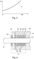
- Figure 8 shows a simplified representation and partially in section of a packing seal 12 with an integrated magnetic bearing 13.
- the packing seal 12 comprises a flange-like fastening part 12c and a cylindrical body part 12p, which are firmly connected to one another via holding means 12o.
- the fastening part 12c is preferably attached to the cylinder housing by means of fastening means 12n. 2a.
- the packing seal 12 comprises at least one sealing ring 12b, and comprises all Figure 5 components shown, which in Figure 8 are not shown in detail.
- piston compressor 1 according to Figure 7 the packing seal 12 is according to Figure 8
- the packing seal 12 could be arranged in a variety of different piston compressors 1, for example in the Figure 1 piston compressor 1 shown.
- the illustrated packing seal 12 for a piston compressor 1 comprises a longitudinal axis L, as well as a flange-shaped fastening part 12c and a cylindrical part 12p following one another in the direction of the longitudinal axis L, wherein in the cylindrical part 12p a magnetic bearing 13 and at least one chamber ring 12a with a sealing ring 12b arranged therein are arranged one after the other in the direction of the longitudinal axis L, wherein the magnetic bearing 13 comprises at least one single controllable electromagnet 13f.
- the magnetic bearing 13 comprises at least two controllable electromagnets 13f, which, as in Figure 6 shown, are arranged opposite one another with respect to the longitudinal axis L in the cylindrical part 12.
- the packing seal comprises at least two emergency bearings 12f, 12g, which are arranged at a distance from one another in the direction of the longitudinal axis L.
- the magnetic bearing 13 is arranged in the direction of the longitudinal axis L between the two emergency bearings 12f, 12g.
- the packing seal also comprises a sensor 26 which is designed to measure the radial position of a piston rod 16 extending through the packing seal with respect to the longitudinal axis L.
- the senor 26 is arranged in the direction of the longitudinal axis L between the two emergency bearings 12f, 12g, wherein the sensor 26 is preferably arranged in the direction of the longitudinal axis L along the magnetic bearing 13.
- the packing seal preferably comprises cooling channels 121, which preferably have connections 12m arranged on the front side of the flange-shaped fastening part 12c.
- the cooling channels 121 preferably run in the direction of the longitudinal axis L along the entire length of the magnetic bearing 13.
- the chamber rings 12a are arranged in the direction of the longitudinal axis L along an end portion L2 of the packing seal 12, wherein the end portion L2 is located at the opposite end of the packing seal with respect to the fastening part 12c.
- the packing seal 12 has a total length L1 in the direction of the longitudinal axis L, and the end section L2 has an end section length L3, wherein the end section length L3 is less than 50% of the total length L1, preferably less than 25%, and particularly preferably less than 10%.
- This design has the advantage that a significant part of the total length L1 is available for the magnetic bearing 13.
- a piston rod 16 running through the packing seal 12 preferably rests against the sealing rings 12b and thus touches them, whereas the piston rod 16 preferably does not touch the packing seal 12 along the remaining total length L1.
- This design has the advantage that within the remaining total length L1 a deflection or movement of the piston rod 16 radially to the longitudinal axis L is possible, wherein the maximum possible movement path is of course limited by the inner cross section of the passage of the packing seal 12 provided for the piston rod 16.
- the piston rod 16 is thus slightly movable in the radial direction relative to the packing seal 12 within the remaining total length L1, so that the position of the piston rod 16 in the radial direction can be corrected particularly well with the aid of the magnetic bearing 13.
- This also makes it particularly advantageous for the position of the piston 3 connected to the piston rod 16 to be corrected in the radial direction relative to the interior of the cylinder 2.
- the sealing ring 12b is radial to the longitudinal direction L in the chamber ring 12a displaceable.
- This design has the advantage that the chamber ring(s) 12a form a type of pivot point relative to which the piston rod 16 can be rotated slightly when the piston rod 16 is displaced in the radial direction by the magnetic bearing 13 in the region of the remaining total length L1, so that the piston 3 connected to the piston rod 16 is preferably displaced in the opposite direction within the cylinder 2.
- This slight displacement of the piston 3 or at least the application of a force acting in the radial direction to the piston 3 preferably takes place at a relatively high frequency, for example at 10, 100 or 1000 Hz, so that the piston 3 is preferably held continuously and preferably in a central position relative to the interior of the cylinder 2.
- the piston compressor comprises a piston which is moved back and forth in the direction of a longitudinal axis within a cylinder, wherein the piston is driven by a crosshead via a piston rod, and comprising a packing seal with a controllable magnetic bearing and at least one chamber ring 12a with a sealing ring 12b arranged therein, wherein the piston rod 16 extends through the packing seal 12, and wherein a controllable magnetic force Fm acting at least perpendicular to the longitudinal axis L is exerted on the piston rod 16 via the controllable magnetic bearing 13.
- a state variable Z of the piston compressor 1 is detected, wherein the magnetic force Fm is controlled as a function of the state variable Z, and wherein a force F h is thereby exerted on the piston 3 via the piston rod 16.
- the state variable Z is measured within the packing seal 12, wherein the controllable magnetic bearing 13 acts via the piston rod 16 to center the position of the piston 3 within the cylinder 7.
- a piston compressor 1 comprising a piston 3 with piston or sealing rings 4 and a guide ring 5.
- the guide ring 5 could be dispensed with.
- the piston 3 could also be designed as a labyrinth piston, wherein this labyrinth piston preferably does not touch the inner wall of the cylinder 2.
Landscapes
- Engineering & Computer Science (AREA)
- Mechanical Engineering (AREA)
- General Engineering & Computer Science (AREA)
- Compressors, Vaccum Pumps And Other Relevant Systems (AREA)
- Compressor (AREA)
- Sealing Devices (AREA)
- Magnetic Bearings And Hydrostatic Bearings (AREA)
- Control Of Positive-Displacement Pumps (AREA)
Description
- Die Erfindung betrifft eine Packungsdichtung für einen Kolbenverdichter sowie ein Verfahren zum Betrieb desselben.
- Das Dokument
US 1526909 offenbart einen Kolbenverdichter mit einer Packungsdichtung. Dieser Kolbenverdichter unterliegt einem relativ grossen Verschleiss, der Kolbenverdichter ist nur mit relativ geringer Drehzahl betreibbar, und ein Tausch der Packungsdichtung ist relativ aufwändig. Das DokumentWO2014/ 139565A1 offenbart einen Kolbenverdichter mit einem horizontal verlaufenden Zylinder in welchem ein in horizontaler Richtung hin und her beweglicher Kolben angeordnet ist. Dieser Kolbenverdichter weist den Nachteil auf, dass die am Kolben angeordneten Führungsringe und/oder Dichtringe einem relativ grossen Verschleiss unterliegen, und dass der Kolbenverdichter nur mit relativ geringer Drehzahl betreibbar ist. Das DokumentDE3805670A1 offenbart einen Kolbenverdichter mit vertikal verlaufendem Zylinder, wobei der Kolben als ein Labyrinthkolben oder als ein mit gefangenen Kolbenringen versehener Kolben ausgestaltet sein kann. Auch dieser Kolbenverdichter weist den Nachteil auf, dass ein Verschleiss auftreten kann. Das DokumentUS4889039 offenbart einen weiteren Kolbenverdichter mit einer Packung, wobei der Kolben als Labyrinthkolben ausgestaltet ist, und wobei die Packung eine Dichtung mit einer Vielzahl von Nuten aufweist, welche ein Abdichten der Kolbenstange gemäss dem Labyrinthprinzip bewirken. Die Kolbenstange und der Kolben werden durch zwei Magnetlager möglichst zentriert gehalten, um ein berührungsloses Bewegen von Kolben und Kolbenstange zu gewährleisten. Das DokumentWO2006/042866 offenbart eine Kolbenstangendichtung umfassend einen Dichtring, dessen Dichtfläche mittels eines Aktuators radial zur Kolbenstange verschiebbar ist. - Aufgabe der Erfindung ist es eine vorteilhaftere Packungsdichtung für einen Kolbenverdichter sowie ein vorteilhafteres Betriebsverfahren eines Kolbenverdichters umfassend die Packungsdichtung auszubilden. Vorzugsweise umfasst der Kolbenverdichter einen Kolben und eine Kolbenstange, die in horizontaler oder in vertikaler Richtung beweglich angeordnet sind.
- Diese Aufgabe wird gelöst mit einer Packungsdichtung für einen Kolbenverdichter aufweisend die Merkmale von Anspruch 1. Die abhängigen Vorrichtungsansprüche betreffen weitere vorteilhafte Ausgestaltungen. Die Aufgabe wird weiter gelöst mit einem Kolbenverdichter gemäss Anspruch 11 umfassend eine in Anspruch 1 definierte Packungsdichtung, und ein Verfahren aufweisend die Merkmale von Anspruch 12. Die abhängigen Verfahrensansprüche betreffen weitere vorteilhafte Verfahrensschritte.
- Die Aufgabe wird insbesondere gelöst mit einer Packungsdichtung für einen Kolbenverdichter, umfassend eine Längsachse sowie in Richtung der Längsachse (L) nacheinander folgend ein Befestigungsteil (12c) und ein zylinderförmiges Teil (12p), wobei im zylinderförmigen Teil (12p) ein Magnetlager und eine Dichtung angeordnet sind, wobei das Magnetlager (13) zumindest einen ansteuerbaren Elektromagneten (13f) umfasst, dadurch gekennzeichnet, dass die Dichtung als Kammerring (12a) mit darin angeordnetem Dichtungsring (12b) ausgestaltet ist, dass der Dichtungsring (12b) radial zur Längsachse (L) im Kammerring (12a) verschiebbar ist, und dass im zylinderförmigen Teil (12p), in Richtung der Längsachse (L) nachfolgend dem Befestigungsteil (12c), das Magnetlager (13) und der Kammerring (12a) nacheinander folgend angeordnet sind.
- Die Aufgabe wird zudem gelöst mit einem Verfahren zum Betrieb eines Kolbenverdichters (1) umfassend einen Kolben (3), der in Richtung einer Längsachse (L) innerhalb eines Zylinders (7) hin und her bewegt wird, wobei der Kolben (3) über eine Kolbenstange (16) angetrieben wird, sowie umfassend eine Packungsdichtung (12) mit einem ansteuerbaren Magnetlager (13) und einer Dichtung, wobei die Kolbenstange (16) durch die Packungsdichtung (12) verläuft, und wobei über das ansteuerbare Magnetlager (13) eine zumindest senkrecht zur Längsachse (L) wirkende, ansteuerbare magnetische Kraft (Fm) auf die Kolbenstange (16) ausgeübt wird, dadurch gekennzeichnet, dass die Kolbenstange (16) in der Dichtung durch einen Kammerring (12a) mit darin angeordnetem Dichtungsring (12b) abgedichtet wird, dass die Kolbenstange (16) zwischen dem Kolben (3) und dem Magnetlager (13) abgedichtet wird, dass die Kolbenstange (16) durch das Magnetlager (13) radial zur Längsachse (L) bewegt wird und dadurch die Auflagekraft des an der Innenoberfläche des Zylinders abgestützten Kolbens reduziert wird, wobei die Kolbenstange (16) am Dichtungsring (12b) anliegt, und der Dichtungsring (12b) radial zur Längsachse (L) bezüglich dem Kammerring (12a) verschoben wird.
- Vorzugsweise ist die Packungsdichtung in einem Kolbenverdichter zum Verdichten eines Gases angeordnet, umfassend einen Zylinder, einen Kolben, eine Kolbenstange, die Packungsdichtung, einen Kreuzkopf, ein Magnetlager sowie einen Antrieb, wobei der Kolben in einer Längsrichtung beweglich innerhalb des Zylinders angeordnet ist, wobei der Kolben über die Kolbenstange mit dem Kreuzkopf verbunden ist, wobei zwischen dem Kolben und dem Kreuzkopf die Packungsdichtung angeordnet ist, durch welche die Kolbenstange verläuft, wobei der Kreuzkopf durch den Antrieb angetrieben ist, wobei zwischen dem Kolben und dem Kreuzkopf das Magnetlager angeordnet ist, und wobei das Magnetlager zumindest senkrecht zur Längsrichtung eine magnetische Kraft auf die Kolbenstange bewirken kann, wobei ein Sensor angeordnet ist zum Erfassen einer Zustandsgrösse des Kolbenverdichters, wobei das Magnetlager als ansteuerbares Magnetlager ausgestaltet ist, und wobei eine Ansteuervorrichtung die vom Magnetlager auf die Kolbenstange bewirkte magnetische Kraft in Abhängigkeit der Zustandsgrösse ansteuert. Der Zylinder verläuft besonders bevorzugt im Wesentlichen in horizontaler Richtung.
- Vorzugsweise ist die Packungsdichtung in einem Kolbenverdichter zum Verdichten eines Gases angeordnet, umfassend einen in Wesentlichen in horizontaler Richtung verlaufenden Zylinder sowie umfassend einen Kolben, eine Kolbenstange, die Packungsdichtung, einen Kreuzkopf sowie einen Antrieb, wobei der Kolben in einer Längsrichtung beweglich innerhalb des Zylinders angeordnet ist, wobei der Kolben über eine Kolbenstange mit dem Kreuzkopf verbunden ist, wobei zwischen dem Kolben und dem Kreuzkopf eine Packungsdichtung angeordnet ist, durch welche die Kolbenstange verläuft, und wobei der Kreuzkopf durch den Antrieb angetrieben ist, wobei zwischen dem Kolben und dem Kreuzkopf zudem ein ansteuerbares Magnetlager angeordnet ist, wobei das Magnetlager zumindest senkrecht zur Längsrichtung eine magnetische Kraft auf die Kolbenstange bewirken kann, und wobei eine Ansteuervorrichtung die vom Magnetlager auf die Kolbenstange bewirkte magnetische Kraft ansteuert.
- Vorzugsweise wird die Packungsdichtung in einem Verfahren zum Betrieb eines Kolbenverdichters verwendet, wobei der Kolbenverdichter einen Kolben umfasst, der in einer Längsrichtung innerhalb eines Zylinders hin und her bewegt wird, wobei der Kolben über eine Kolbenstange angetrieben wird, und wobei eine zumindest senkrecht zur Längsrichtung wirkende, magnetische Kraft auf die Kolbenstange ausgeübt wird, wobei eine Zustandsgrösse des Kolbenverdichters erfasst wird, wobei die magnetische Kraft in Abhängigkeit der Zustandsgrösse angesteuert wird, und wobei dadurch über die Kolbenstange eine Kraft, vorzugsweise eine Entlastungskraft, auf den Kolben bewirkt wird. Besonders bevorzugt verläuft die Längsrichtung im Wesentlichen in horizontaler Richtung.
- Vorzugsweise wird die Packungsdichtung in einem Verfahren zum Betrieb eines Kolbenverdichters verwendet, wobei der Kolbenverdichter einen Kolben umfasst, der in einer Längsrichtung innerhalb eines Zylinders hin und her bewegt wird, wobei die Längsrichtung im Wesentlichen in horizontaler Richtung verläuft, wobei der Kolben über eine Kolbenstange angetrieben wird, wobei eine ansteuerbare, zumindest senkrecht zur Längsrichtung wirkende, magnetische Kraft auf die Kolbenstange ausgeübt wird und dadurch über die Kolbenstange eine Entlastungskraft auf den Kolben bewirkt wird, wobei die magnetische Kraft in Abhängigkeit einer Zustandsgrösse angesteuert wird.
- Die erfindungsgemässe Packungsdichtung für einen Kolbenverdichter umfasst ein ansteuerbares Magnetlager, welches zwischen einem Kolben und einem Kreuzkopf des Kolbenverdichters angeordnet ist, wobei eine Kolbenstange den Kolben mit dem Kreuzkopf verbindet, wobei die Kolbenstange durch das magnetische Magnetlager verläuft, und wobei das Magnetlager zumindest senkrecht zur Verlaufsrichtung der Kolbenstange eine ansteuerbare, magnetische Anziehungskraft auf die Kolbenstange ausübt. Die erfindungsgemässe Packungsdichtung umfasst zudem vorzugsweise zumindest einen Sensor, der mit einer Ansteuervorrichtung verbindbar ist, wobei die Ansteuervorrichtung ausgestaltet ist um im ansteuerbaren Magnetlager angeordnete Elektromagnete mit elektrischem Strom bzw. elektrischer Leistung zu versorgen, wobei die Ansteuervorrichtung den zugeführten Strom bzw. die zugeführte Leistung in Abhängigkeit des vom Sensor gemessenen Wertes moduliert bzw. verändert, um die Lage des Kolbens bezüglich des Zylinders zu beeinflussen, sodass der Kolben innerhalb des Zylinders zumindest zeitweise eine vorteilhafte Lage aufweist. Das ansteuerbare Magnetlager ist vorzugsweise als Radiallager ausgestaltet, umfassend eine Mehrzahl von in Umfangsrichtung verteilt angeordnete, von der Ansteuervorrichtung ansteuerbare Elektromagnete. Das Magnetlager könnte jedoch auch derart ausgestaltet sein, dass die Magnetkraft nur in einer Richtung bzw. in einer Dimension wirkt, beispielsweise indem zwei ansteuerbare Elektromagnete bezüglich der Kolbenstange gegenüberliegend bzw. symmetrisch angeordnet sind, sodass eine von diesen Elektromagneten auf die Kolbenstange bewirkte Magnetkraft nur in einer Dimension wirkt.
- Der Kolbenverdichter umfasst zumindest einen Zylinder sowie jeweils einen innerhalb des Zylinders hin- und her beweglich angeordneten Kolben, wobei der Zylinderinnenraum und somit auch die Bewegung des Kolbens in einer bevorzugten Ausgestaltung in horizontaler Richtung oder im Wesentlichen in horizontaler Richtung verläuft, wobei ein derartiger Kolbenverdichter auch als horizontaler Kolbenverdichter bezeichnet wird. Unter Kolbenverdichter wird hierin vorzugsweise ein Hubkolbenverdichter verstanden. Das Magnetlager übt zumindest senkrecht zur Verlaufsrichtung der Kolbenstange eine ansteuerbare, magnetische Anziehungskraft auf die Kolbenstange aus, und bewirkt somit vorzugsweise eine vertikal nach Oben gerichtete Kraft auf die Kolbenstange, vorzugsweise in einer zur Schwerkraft entgegengesetzten Richtung.
- In einer vorteilhaften Ausgestaltung umfasst der in horizontaler Richtung bewegliche Kolben einen sogenannten Führungsring, welcher an der Innenoberfläche des Zylinders aufliegt. Die vom Magnetlager zumindest in vertikaler Richtung auf die Kolbenstange ausgeübte Anziehungskraft und/oder die auf die Kolbenstange ausgeübte Abstossungskraft hat zur Folge, dass die Auflagekraft eines an der Innenoberfläche des Zylinders abgestützten Kolbens reduziert wird, oder dass der Kolben bzw. der Führungsring die Innenoberfläche des Zylinders nicht mehr berührt, sodass der Kolben bzw. der Führungsring des Kolbens entweder nur mit reduzierter Auflagekraft an der Innenoberfläche des Zylinders aufliegt, und besonders vorteilhaft sich ohne eine Berührung der Innenoberfläche des Zylinders innerhalb des Zylinders hin und her bewegt. Falls ein Kolben einen Führungsring aufweist, so ergibt sich aus der Verwendung des Magnetlagers der Vorteil, dass die Auflagekraft des Führungsrings an der Innenoberfläche und dadurch der Verschleiss des Führungsrings reduziert wird, sodass der Führungsring eine höhere Standzeit bzw. eine höhere Lebensdauer aufweist, bis dieser zu ersetzen ist. Zudem ergibt sich der Vorteil, dass der Kolbenverdichter, falls erwünscht, mit einer höheren Drehzahl betreibbar ist, wobei dabei vorzugsweise kein erhöhter Verschleiss oder keine erhöhte Erwärmung auftritt.
- Besonders vorteilhaft wird die erfindungsgemässe Packungsdichtung in Kombination mit einem Kolben verwendet, der als ein Labyrinthkolben ausgestaltet, wobei ein solcher Labyrinthkolben, wie an sich bekannt, an dessen Oberfläche eine Labyrinthstruktur aufweist, welche zur Abdichtung zwischen Kolben und Innenoberfläche des Zylinders dient. Die vom Magnetlager auf die Kolbenstange bewirkte Anziehungskraft wird dabei vorzugsweise derart angesteuert, dass der sich hin und her bewegende Kolben entlang des gesamten Hubweges die Innenoberfläche des Zylinders nicht berührt, indem das Magnetleger vorzugsweise bestrebt ist den Kolben in einer mittigen Lage bezüglich dem Innenraum des Zylinders zu halten. Die erfindungsgemässe Packungsdichtung ist jedoch auch für Kolbenverdichter umfassend Kolben mit Kolbenringen und gegebenenfalls zusätzlich aufweisend Führungsringe geeignet. Der hierin beschriebene Kolbenverdichter kann beispielsweise nur einen einzigen Kolben mit Kolbenstange und Zylinder aufweisen, oder vorzugsweise eine Mehrzahl von Kolben, Kolbenstangen und Zylindern, wobei in diesem Fall vorzugsweise jede Kolbenstange durch je eine erfindungsgemässe Packungsdichtung verläuft.
- In einer weiteren, bevorzugten Ausgestaltung verläuft der Zylinderinnenraum und somit auch die Bewegung des Kolbens in vertikaler Richtung oder im Wesentlichen in vertikaler Richtung. Das Magnetlager übt zumindest senkrecht zur Verlaufsrichtung der Kolbenstange eine ansteuerbare, magnetische Anziehungskraft auf die Kolbenstange aus, und bewirkt somit eine radial oder im Wesentlichen radial zur Kolbenstange verlaufende Kraft auf die Kolbenstange und den Kolben aus. Die vom Magnetlager zumindest in radialer Richtung auf die Kolbenstange ausgeübte Anziehungskraft und/oder die auf die Kolbenstange ausgeübte Abstossungskraft hat zur Folge, dass die Anlagekraft eines an der Innenoberfläche des Zylinders anliegenden Kolbenrings, und insbesondere eine einseitig Anlagekraft, reduziert wird, oder dass der Kolben bzw. dessen Kolbenring, und insbesondere ein als Labyrinthkolben ausgestalteter Kolben, die Innenoberfläche des Zylinders nicht mehr berührt, sodass der Kolben bzw. der Kolbenring entweder nur mit reduzierter Anlagekraft an der Innenoberfläche des Zylinders anliegt, und besonders vorteilhaft der Labyrinthkolben sich ohne eine Berührung der Innenoberfläche des Zylinders innerhalb des Zylinders hin und her bewegt. Die Verwendung des Magnetlagers ergibt den Vorteil, dass ein Verschleiss des Kolbenrings reduziert wird, sodass der Kolbenkompressor eine höhere Standzeit bzw. eine höhere Lebensdauer aufweist, bis dieser zu warten ist. Zudem besteht die Option den Kolbenverdichter mit einer höheren Drehzahl zu betreiben. Sofern der Kolbenkompressor einen Labyrinthkolben aufweist, so ergibt die Verwendung des Magnetlagers den Vorteil, dass eine Berührung zwischen Labyrinthkolben und Innenoberfläche des Zylinders noch besser vermieden werden kann, da eine allenfalls exzentrische Anordnung des Labyrinthkolbens bezüglich dem Innenraum des Zylinders mit Hilfe des Magnetlagers zumindest teilweise korrigiert werden kann, und der Kolben vorzugsweise im Innenraum des Zylinders bezüglich dessen Längsachse zentriert wird, sodass keine gegenseitige Berührung auftritt. Die Verwendung des Magnetlagers ergibt den zusätzlichen Vorteil, dass der Kolbenkompressor auch mit einer reduzierten Spaltbreite zwischen Labyrinthkolbenaussenfläche und der Innenoberfläche des Zylinders sicher betreibbar ist, ohne dass eine gegenseitige Berührung auftritt. Diese reduzierte Spaltbreite erhöht den Wirkungsgrad des Kolbenkompressors bzw. reduziert den Verlust während der Kompression.
- In einer weiteren, bevorzugten Ausgestaltung weist der Kolbenkompressor zumindest einen Kolben und einen Zylinder auf, und vorzugsweise eine Mehrzahl von Kolben und Zylindern, welche vorzugsweise auf einem gemeinsamen Gestellt angeordnet sind, und welche vorzugsweise von einem gemeinsamen Kurbelwelle angetrieben werden. In einer bevorzugten Ausgestaltung ist ein solcher Kolbenkompressor auf einem Schiff angeordnet, wobei der Zylinder, der Zylinderinnenraum und somit auch die Bewegung des Kolbens bei ruhiger See in vertikaler Richtung oder im Wesentlichen in vertikaler Richtung verlaufen. Eine unruhige oder stürmische See hat zur Folge, dass das Schiff mit zunehmender Wellenhöhe eine zunehmende Roll- oder Stampfbewegung ausführt, was zur Folge hat, dass der gesamte Kolbenkompressor und somit insbesondere auch die Längsrichtung der Kolbenstange eine abhängig vom Wellengang in Funktion der Zeit variable, von der Vertikalen um einen Winkel Beta abweichenden Verlauf aufweist. In einer vorteilhaften Ausgestaltung wird der Winkel Beta, und vorzugsweise der Winkel Beta in Funktion der Zeit, als zusätzliche Zustandsgrösse gemessen.
- Auf einem Schiff wird ein mehrstufiger Kolbenkompressor zum Beispiel zum Verdichten von sich in einem Flüssiggasbehälter ansammelnden Abdampfgas auf einen Druck von 200 bis 500 Bar verwendet, um mit dem komprimierten Gas einen Gasmotor bzw. einen Dieselmotor des Schiffes mit Brennstoff zu versorgen. Ein auf einem Schiff angeordneter Kolbenkompressor wird vorzugsweise derart betrieben, dass die vom Magnetlager zumindest in radialer Richtung auf die Kolbenstange ausgeübte Kraft derart in Funktion der Zustandsgrösse und der zusätzlichen Zustandsgrösse angesteuert wird, dass die Anlagekraft eines an der Innenoberfläche des Zylinders anliegenden Kolbenrings, und insbesondere eine einseitig Anlagekraft, reduziert wird, oder dass der Kolben bzw. dessen Kolbenring, und insbesondere ein als Labyrinthkolben ausgestalteter Kolben, die Innenoberfläche des Zylinders nicht mehr berührt, sodass auf einem Schiff auch bei Wellengang gewährleistet ist, dass der/die Kolben bzw. der/die Kolbenringe des Kolbenkompressors entweder nur mit reduzierter Anlagekraft an der Innenoberfläche des Zylinders anliegt, und besonders vorteilhaft der/die Labyrinthkolben sich ohne eine Berührung der Innenoberfläche des Zylinders innerhalb des Zylinders hin und her bewegten. Die Verwendung des Magnetlagers ergibt den Vorteil, dass auch bei Wellengang ein Verschleiss des Kolbenrings reduziert wird, bzw. dass eine Berührung der Labyrinthstruktur des Labyrinthkolbens mit der Innenwand des Zylinders vermieden wird, insbesondere auch bei geringer Spaltbreite zwischen Kolbenaussendurchmesser und Zylinderinnenwand, sodass ein auf einem Schiff angeordneter Kolbenkompressor eine höhere Standzeit bzw. eine höhere Lebensdauer aufweist, bis dieser zu warten ist. Das Magnetlager wird vorzugsweise derart angesteuert, dass das Magnetlager radial zur Längsachse der Kolbenstange eine dämpfende Wirkung auf die Kolbenstange ausübt, um eine Bewegung der Kolbenstange und des Kolbens in zur Längssachse radialen Richtung zu dämpfen, um beispielsweise die maximale Amplitude auftretender Resonanzschwingungen oder anderer Querschwingungen des Kolbens, beispielsweise verursacht durch Wellengang, zu reduzieren.
- Da die Wellenbewegung beziehungsweise die gemessene und daraus abgeleitete zusätzliche Zustandsgrösse im Vergleich zur Drehzahl des Kolbenkompressors einen relativ langsam ablaufenden Prozess darstellt, und die Periodendauer einer Wellenbewegung des Wassers im Vergleich zur Periodendauer einer Umdrehung des Kolbenkompressors um einen Faktor 10 bis 1000 langsam ist, ist es möglich eine kurzfristige Veränderung der zusätzlichen Zustandsgrösse vorauszuberechnen, und diesen Wert in die Ansteuerung des Magnetlagers einfliessen zu lassen, indem das Magnetlager mit eine vorausschauende Steuerung angesteuert wird, welche die auf Grund des Wellengangs zu erwartende Bewegung des Kolbenkompressors beispielweise für einen Zeitpunkt, der beispielsweise im Bereich zwischen 1 bis 50 Sekunden liegen kann, voraussagt, und das Magnetlager entsprechend ansteuert, sodass bei der Beeinflussung bzw. Ansteuerung der Lage der Kolbenstange bzw. des Kolbens die zu erwartende , durch den Wellengang verursachte Bewegung des Kolbenkompressors mit berücksichtigt wird.
- Die erfindungsgemässe Packungsdichtung in Kombination mit dem Kolbenverdichter weist zudem den Vorteil auf, dass dieser mit einer höheren Drehungszahl beziehungsweise mit einer höheren mittleren Kolbengeschwindigkeit betreibbar ist, da der Kolben bzw. der Führungsring die Zylinderinnenwand entweder gar nicht mehr berührt, oder nur noch mit reduzierter Auflagekraft an der Zylinderinnenwand anliegt. Ein derartiger Betrieb mit höherer Umdrehungszahl ist insbesondere vorteilhaft bei einem Kolbenkompressor mit einem sogenannten trocken laufenden Kolben, das heisst einem Labyrinthkolben, oder einem Kolben mit selbstschmierenden Dichtungsringen, das heisst einem Kolben, dessen Kolben- bzw. Dichtungsringe nicht ölgeschmiert sind, was auch als ein ungeschmierter Kolben bezeichnet wird. Das ansteuerbare Magnetlager kann entweder als tragendes Lager verwendet werden, durch welches der Kolben ohne eine Berührung der Innenoberfläche des Zylinders gehalten wird, oder es kann als Entlastungslager verwendet werden, durch welches die vom Kolben auf die Innenoberfläche des Zylinders bewirkte Kraft reduziert wird, wobei der Kolben in diesem Fall die Innenwand berührt. Das ansteuerbare Magnetlager kann auch einen zentrierende Funktion bei einem im Wesentlichen vertikal verlaufenden Kolben übernehmen, durch welche der Kolben zentriert, und vorzugsweise ohne eine Berührung der Innenoberfläche des Zylinders gehalten wird.
- Das Magnetlager ist in einem Ausführungsbeispiel an einer vorgegebenen Stelle im horizontalen Kolbenverdichter angeordnet, wogegen sich die Lage des Schwerpunkts des Kolben durch die Hin- und Herbewegung während des Betriebs ständig verändert, sodass sich während des Betriebs die Länge des durch die Kolbenstange zwischen dem magnetischen Magnetlager und dem Schwerpunkt des Kolbens gebildeten Hebelarms ständig verändert. Eine zur Stromversorgung des Magnetlagers vorgesehene Ansteuervorrichtung ist daher vorteilhafterweise derart ausgestaltet, dass die vom magnetischen Magnetlager auf die Kolbenstange bewirkte magnetische Kraft in Abhängigkeit der Stellung des Kolbens beziehungsweise in Abhängigkeit der Länge des vorhin genannten Hebelarms angesteuert verändert wird. Vorteilhafterweise wird zumindest eine in vertikaler Richtung wirkende Kraft auf die Kolbenstange ausgeübt. Besonders vorteilhaft ist das Magnetlager als Radiallager ausgestaltet, das, senkrecht zur Längsrichtung der Kolbenstange, eine in zwei Dimensionen ansteuerbare Kraft auf die Kolbenstange ausüben kann, vorzugsweise eine Kraft in vertikaler Richtung und eine Kraft in horizontaler Richtung. Vorteilhafterweise wird ein solches Radiallager derart angesteuert, dass der Kolben während dem Betrieb in jeder seiner möglichen Stellungen die Innenoberfläche des Zylinders nicht berührt, weder eine untere noch eine obere noch eine seitliche Innenfläche des Zylinders.
- Das Magnetlager wird vorzugsweise in Abhängigkeit einer gemessenen Zustandsgrösse angesteuert, insbesondere wenn der Kolben während dem Betrieb die Innenoberfläche des Zylinders nicht berühren soll, wobei die Zustandsgrösse zumindest eine der nachfolgenden Grössen umfasst: Verschiebeweg des Kolbens im Zylinder, Verschiebeweg der Kolbenstange in Verlaufsrichtung der Kolbenstange, Verschiebeweg der Kolbenstange senkrecht zur Verlaufsrichtung der Kolbenstange, sowie Drehwinkel der Antriebswelle. In einer weiteren vorteilhaften Ausgestaltung ist als Zustandsgrösse der Abstand der Kolbenstange bezüglich dem Magnetlager geeignet, zumindest in vertikaler Richtung, und insbesondere die Spaltbreite im Magnetlager zwischen Kolbenstange und Magnetlager.
- Der Sensor zum Erfassen der Zustandsgrösse ist vorteilhafterweise zum Erfassen zumindest einer der nachfolgenden Grössen ausgestaltet: Neigungswinkel β der Längsrichtung gegenüber der Vertikalen, Neigungswinkel β in Funktion der Zeit, Spaltbreite zwischen Zylinderinnenfläche und Kolbenseitenfläche, Ort einer gegenseitigen Berührungsstelle von Kolben und Zylinder.
- Die Packungsdichtung wird vorzugsweise in Kombination mit dem Kolbenkompressor verwendet, wobei die Kolbenstange durch diese Packungsdichtung bzw. deren Dichtungsringe verläuft, um den Zylinderinnenraum gegen Aussen abzudichten, wobei die Packungsdichtung nebst den Dichtungsringen zudem noch das Magnetlager aufweist. Die erfindungsgemässe Packungsdichtung ist besonders vorteilhaft als ein Austauschteil ausgestaltet, sodass die Packungsdichtung gesamthaft, das heisst als eine Einheit, aus dem Kolbenkompressor entfernt und wieder eingebaut oder durch eine neue Packungsdichtung ersetzt werden kann. Besonders vorteilhaft weist die erfindungsgemässe Packungsdichtung dieselben oder im Wesentlichen dieselben Aussenmasse auf wie bisher bekannte Packungsdichtungen ohne Magnetlager, sodass die erfindungsgemässe Packungsdichtung umfassend das Magnetlager zum Einbau in bestehende Kolbenkompressoren verwendet werden kann, um diese nachzurüsten und qualitativ zu verbessern.
- In einer weiteren, vorteilhaften Ausgestaltung umfasst die erfindungsgemässe Packungsdichtung zudem noch Kühlkanäle. Bei einer im Kolbenkompressor montierten erfindungsgemässen Packungsdichtung sind diese Kühlkanäle mit einem Kühlkreislauf verbunden, um das magnetische Magnetlager und/oder die Packungsdichtung zu kühlen.
- Die zur Erläuterung der Ausführungsbeispiele verwendeten Zeichnungen zeigen:
- Fig. 1
- einen schematisch vereinfachten Längsschnitt durch einen Kolbenverdichter;
- Fig. 2
- schematisch eine Regelungsvorrichtung;
- Fig. 3
- ein beispielhafter Verlauf der magnetischen Kraft in Funktion einer Zustandsgrösse, nämlich des Drehwinkels einer Antriebswelle;
- Fig. 4
- einen Längsschnitt durch eine bekannte Packungsdichtung;
- Fig. 5
- einen Längsschnitt durch eine Packungsdichtung gemäss der Erfindung;
- Fig. 6
- ein radiales Magnetlager;
- Fig. 7
- ein geneigt angeordneter Kolbenverdichter, beispielsweise auf einem Schiff mit Wellengang;
- Fig. 8
- eine vereinfachte Darstellung eine Packungsdichtung mit Magnetlager.
- Grundsätzlich sind in den Zeichnungen gleiche Teile mit gleichen Bezugszeichen versehen.
-
Fig. 1 zeigt einen Kolbenverdichter 1 zum Verdichten eines Gases, umfassend einen in horizontaler Richtung verlaufenden Zylinder 2 sowie umfassend einen innerhalb des Zylinders 2 in Verlaufsrichtung des Zylinders 2 bzw. in Längsrichtung L beweglichen Kolben 3. Der Kolbenverdichter 1 umfasst zudem eine Kolbenstange 16, eine Packungsdichtung 12, ein Magnetlager 13, einen Kreuzkopf 17 mit einer Linearführung 18, eine Schubstange 19 sowie einen Antrieb, beispielsweise eine Kurbel 20 mit einer Antriebswelle 21. Der Kolben 3 ist im dargestellten Ausführungsbeispiel doppelwirkend ausgestaltet und umfasst Dichtungs- bzw. Kolbenringe 4 sowie einen Führungsring 5, wobei der Kolben 3 den Innenraum des Zylinders 2 in einen ersten Innenraum 6 sowie einen zweiten Innenraum 7 unterteilt, wobei diese beiden Innenräume je ein Eingangsventil 8, 9 sowie je ein Ausgangsventil 10, 11 aufweisen. Der Zylinder 2 ist über ein Zwischenstück 14 mit einem Gehäuse 15 verbunden, wobei in dem Zwischenstück zudem die Packungsdichtung 12 und das Magnetlager 13 angeordnet sind. Das Magnetlager 13 bewirkt zumindest in vertikaler Richtung eine magnetische Kraft Fm auf die Kolbenstange 16. Eine Ansteuervorrichtung 22 erfasst über eine Signalleitung 24 und einen nicht dargestellten Sensor eine Zustandsgrösse Z des Kolbenkompressors 1, beispielsweise den Verschiebeweg s(t) des Kolbens im Zylinder 7 in Funktion der Zeit, den Verschiebeweg s(t) der Kolbenstange 16 und/oder einen Drehwinkel α(t) der Antriebswelle 21 in Funktion der Zeit. Die Ansteuervorrichtung 22 steuert den Strom in den Elektromagneten des Magnetlagers 13 und dadurch die von den Magneten auf die Kolbenstange 16 bewirkte magnetische Kraft über eine Signalleitung 25 an. - Die Ansteuervorrichtung 22 kann in einer einfachen Ausführungsform in einem Ansteuermodus betrieben werden, bei welchem eine Zustandsgrösse Z gemessen wird, und die magnetische Kraft Fm in Funktion der Zustandsgrösse Z verändert wird. Dabei kann auf eine Rückkoppelung verzichtet werden.
Figur 3 zeigt beispielhaft einen derartigen Ansteuermodus, bei welchem der Verlauf einer Kurve K1 vorgegeben wird, wobei die Kurve K1 den Zusammenhang der Zustandsgrösse Z, im vorliegenden Fall der Drehwinkel α der Antriebswelle 21, sowie die in Funktion des Drehwinkels α zu erzeugende magnetische Kraft Fm vorgibt. Im dargestellten Ausführungsbeispiel entspricht der Winkel α=0° dem unteren Totpunkt und α=180° dem oberen Totpunkt des Kolbens 3 bezüglich dem zweiten Innenraum 7, wobei die magnetische Kraft Fm am unteren Totpunkt am kleinsten ist, weil der durch die Kolbenstange 16 zwischen dem Schwerpunkt S des Kolbens 3 und dem Magnetlager 13 gebildete Hebelarm am kürzesten ist, und wobei die magnetische Kraft Fm am oberen Totpunkt am grössten ist, weil der durch die Kolbenstange 16 zwischen dem Schwerpunkt S des Kolbens 3 und dem Magnetlager 13 gebildete Hebelarm am längsten ist. Der Drehwinkels α wird mit einem nicht dargestellten Sensor gemessen und über die Signalleitung 24 der Ansteuervorrichtung 22 zugeführt. Der Kurvenverlauf K1 kann beispielsweise auf Grund von Erfahrungswerten vorgegeben werden. Diese Ausführungsform ist besonders vorteilhaft, wenn, wie inFigur 1 dargestellt, ein Kolben 3 aufweisend einen Führungsring 5 verwendet wird, wobei der Führungsring 5 an der Innenoberfläche des Zylinders 2 anliegt, und wobei die magnetische Kraft Fm dazu dient die Auflagekraft des Führungsrings 5 an der Innenoberfläche des Zylinders 2 zu reduzieren, um dadurch insbesondere einen Verschleiss des Führungsrings 5 zu reduzieren. Die inFigur 3 dargestellte Kurve K1 zeigt nur den Verlauf der magnetischen Kraft Fm in Funktion des Kurbelwellenwinkels α zwischen 0° und 180°. Im nachfolgenden, nicht dargestellten Abschnitt zwischen 180° und 360°, verläuft die Kraft Fm, ausgehend vom Wert bei 180°, in umgekehrter Richtung bis zum Wert von Fm beim Winkel von 0°, wobei dieser Wert identisch zum Wert beim Winkel von 360°. - In einer weiteren vorteilhaften Ausgestaltung ist eine Messvorrichtung, beispielsweise ein Sensor 26 vorgesehen, um die Lage der Kolbenstange 16 und/oder des Kolbens 3 zumindest in vertikaler Richtung zu messen.
Figur 2 zeigt ein Ausführungsbeispiel, welches die Lage der Kolbenstange 16 in vertikaler Richtung misst. In einer vorteilhaften Ausgestaltung ist der Sensor 26 nahe dem Magnetlager 13 oder sogar innerhalb des Magnetlagers 13 angeordnet, wobei der Sensor 26 vorteilhafterweise die Distanz D zwischen einem oberen Spulenkern 13a des Magnetlagers 13 und der Oberfläche der Kolbenstange 16 misst. Das Magnetlager 13 umfasst vorteilhafterweise zumindest einen oberen Spulenkern 13a mit Spule 13b sowie einen unteren Spulenkern 13c mit Spule 13d. Das Magnetlager 13 kann, wie inFigur 6 dargestellt, auch als radiales Magnetlager ausgestaltet sein, mit einer Mehrzahl von in Umfangsrichtung verteilt angeordneten Elektromagneten 13f, wobei deren Spulen 13b, 13d vorzugsweise einzeln ansteuerbar sind, sodass durch eine entsprechende Ansteuerung der Spulen 13b, 13d die Richtung der auf die Kolbenstange 16 bewirkte magnetische Kraft Fm bestimmt werden kann. - In einem vorteilhaften Betriebsverfahren wird der Ansteuervorrichtung 22 über die Sollwertvorgabe 28 ein Sollwert für die Distanz D vorgegeben, wobei die Ansteuervorrichtung 22 die Spulen 13b, 13d derart über die Signalleitung 25 mit Strom ansteuert, der die Kolbenstange 16 unabhängig von Hub s(t) bzw. vom Kurbelwellenwinkel α(t) eine im Wesentliche gleichbleibende, konstante Distanz D bezüglich dem oberen Spulenkern 13a aufweist. Die Kolbenstange 16 wirkt dabei als magnetischer Anker der beiden Spulenkerne 13a, 13b. Vorzugsweise kann das Magnetlager 13 sowohl eine nach oben gerichtete Kraft als auch eine nach unten gerichtet magnetische Anziehungskraft auf die Kolbenstange 16 bewirken, sodass die Lage der Kolbenstange 16 relativ zum Magnetlager 13 besonders präzise ansteuerbar ist.
- Der Kolbenverdichter 1 wird somit vorteilhafterweise derart betrieben, dass eine ansteuerbare magnetische Kraft Fm auf die Kolbenstange 16 ausgeübt wird, sodass über die Kolbenstange 16 eine zumindest in vertikaler Richtung wirkende Kraft Fm, bzw. eine Entlastungskraft Fh, auf den Kolben 3 bewirkt wird, welcher der Schwerkraft F entgegenwirkt, wobei die magnetische Kraft Fm abhängig von einer Zustandsgrösse Z wie beispielsweise der Distanz D, dem Hub s(t) oder dem Drehwinkel α(t) angesteuert bzw. verändert wird. Die in den
Figuren 1 bis 3 beschriebene Anordnung sowie das beschriebene Verfahren ist auch zum Betrieb bzw. zur Ansteuerung eines Kolbenverdichters mit einem in vertikaler Richtung verlaufenden Zylinder und in vertikaler Richtung beweglichem Kolben geeignet. -
Figur 7 zeigt ein weiteres Ausführungsbeispiel eines Kolbenverdichters, der im Vergleich zu dem inFigur 1 dargestellten Kolbenverdichter 1 mit einem im Wesentlichen in vertikaler Richtung verlaufenden Zylinder 2 bzw. Zylinderinnenraum, mit einer im Wesentlichen in vertikaler Richtung verlaufenden Kolbenstange 16, sowie mit einem in dieser Richtung beweglichen Kolben 3 ausgestaltet ist. Zudem zeigtFigur 7 eine Packungsdichtung 12, in welcher das Radiallager 13 integriert ist. Das Radiallager 13 wird über die Leitung 25 mit Strom versorgt, und ist über die Leitung 27 mit einem Kühlmittelkreislauf verbunden. InFigur 7 ist der Kolbenverdichter 1 auf einem Schiff mit einer Krängung mit Krängungswinkel angeordnet, weshalb der Zylinder 2 und die Kolbenstange 16 gegenüber der Vertikalen V einen Neigungswinkel β aufweisen. Der Kolbenverdichter 1 ist vorzugsweise derart im Schiff angeordnet, dass der Zylinder 2 und die Kolbenstange 16 bei absolut ruhiger See genau in vertikaler Richtung oder zumindest annähernd in vertikaler Richtung verlaufen. Der Kolbenverdichter 1 könnte natürlich auch auf dem Land angeordnet sein, und der Zylinder 2 und die Kolbenstange 16 vorzugsweise genau in vertikaler Richtung oder zumindest annähernd in vertikaler Richtung verlaufen. Vorzugsweise wird der Neigungswinkel β bezüglich der Vertikalen V mit einem nicht dargestellten Sensor 26 gemessen, wobei der Neigungswinkel β vorzugsweise in Funktion der Zeit t gemessen wird. Das Magnetlager 13 wird über die Ansteuervorrichtung 22 derart angesteuert, dass auf die Kolbenstange 16 eine magnetische Kraft Fm bewirkt wird, und dass die Kolbenstange 16 eine Entlastungskraft Fn auf den Kolben 3 überträgt, sodass, bedingt durch die einwirkende Entlastungskraft Fh, die Lage des Kolbens 3 innerhalb des Zylinders 2, sofern möglich, beeinflusst wird. - Als Zustandsgrösse Z zur Ansteuerung des Magnetlagers 13, ist, nebst oder anstelle der bereits erwähnten Zustandsgrössen Z, zumindest eine der nachfolgenden Grössen geeignet: Neigungswinkel β des Zylinders gegenüber der Vertikalen V, Spaltbreite zwischen Zylinderinnenfläche und Kolbenseitenfläche, Ort einer gegenseitigen Berührungsstelle von Kolben und Zylinder.
- Vorteilhafterweise wird das Magnetlager 13 derart angesteuert, dass der gegenseitige Abstand von Kolbenstange 16 und Magnetlager 13 und/oder der Abstand von Zylinderinnenfläche und Kolbenseitenfläche, senkrecht zur Längsrichtung L, konstant oder im Wesentlichen konstant gehalten wird. Vorzugsweise wird der Kolben 3 ohne Wandberührung im Zylinder 7 gehalten. Vorzugsweise wird als Zustandsgrösse Z zudem der zwischen der Vertikalen V und der Längsrichtung L eingenommene Neigungswinkel β(t) in Funktion der Zeit t gemessen. Besonders vorteilhaft wird bei einem auf einem Schiff angeordneten Kolbenverdichter die magnetische Kraft Fm mittels einer vorausschauenden Steuerung angesteuert. Vorteilhafterweise umfasst die Zustandsgrösse Z den Neigungswinkel β(t) in Funktion der Zeit t, sodass die Zustandsgrösse Z von der Zeit t abhängig ist. In einer vorteilhaften Ausgestaltung umfasst die Zustandsgrösse Z nebst dem Neigungswinkel β(t) in Funktion der Zeit t zumindest noch eine weitere, hierin genannte Zustandsgrösse, sodass eine derartige, resultierende Zustandsgrösse aus einer Kombination von zumindest zwei hierin genannten Zustandsgrössen besteht. Beispielsweise könnte eine resultierende Zustandsgrösse die Zustandsgrösse Z der Bewegung der Kolbenstange senkrecht zur Längsrichtung L umfassen, und mit der Zustandsgrösse Z des Neigungswinkel β(t) in Funktion der Zeit t kombiniert werden, sodass mit Hilfe der vorausschauenden Steuerung und der Kenntnis der Zustandsgrösse Z des Neigungswinkel β(t) in Funktion der Zeit t die durch den Neigungswinkel β(t) zum Zeitpunkt t +Δt verursachte, zu erwartende Bewegung der Kolbenstange senkrecht zur Längsrichtung L vorausberechnet werden kann, und das Magnetlager 12 mit dieser vorausschauende Zustandsgrösse Zv(t +Δt) angesteuert werden kann.
- Vorteilhafterweise wird aus der Zustandsgrösse Z(t) in Abhängigkeit des Neigungswinkels β(t) für einen zukünftigen Zeitpunkt t+Δt eine vorausschauende Zustandsgrösse Zv(t +Δt) berechnet, und wird die magnetische Kraft Fm zum aktuellen Zeitpunkt t in Abhängigkeit der vorausschauende Zustandsgrösse Zv(t +Δt) angesteuert.
- Besonders vorteilhaft wird der erfindungsgemässe Kolbenverdichter umfassend das ansteuerbare Magnetlager in Kombination mit einem Transportschiff verwendet, das für Transporte über das Meer eingesetzt wird.
- Der in
Figur 4 dargestellte Längsschnitt zeigt eine an sich bekannte Packungsdichtung 12, umfassend eine Mehrzahl von Kammerringen 12a in welchen Dichtungsringe 12b angeordnet sind. Zudem umfasst die Packungsdichtung 12 ein als Flansch ausgestaltetes Befestigungsteil 12c, an welchem auf nicht im Detail dargestellte Weise, alle Kammerringe 12a befestigt sind. Die Packungsdichtung 12 ist über das Befestigungsteil 12c mit einem Zylindergehäuse 2a eines Zylinders 2 verbunden, wobei eine Kolbenstange 16 durch die Packungsdichtung 12 verläuft. Das Zylindergehäuse 2a weist eine Ausnehmung auf, welche einer Aussenkontur 12d der Packungsdichtung 12 entspricht, sodass die gesamte Packungsdichtung 12 in diese Ausnehmung einführbar ist, und falls erforderlich die gesamte Packungsdichtung 12 vorzugsweise nach dem Lösen des Befestigungsteils 12c vom Zylindergehäuse 2a als gesamte Einheit ersetzt werden kann. -
Figur 5 zeigt einen Längsschnitt durch eine erfindungsgemässe Packungsdichtung 12 umfassend ein Magnetlager 13.Figur 6 zeigt einen Teilabschnitt des Magnetlagers 13, das als Radiallager ausgestaltet ist und beispielsweise acht Spulenkerne 13a, 13c umfasst, wobei die zwei gegenüber liegenden Spulenkerne 13a, 13c mit Bezugszeichen versehen sind. Die Spulenkerne 13a, 13c sind mit Spulen 13b, 13d umwickelt. Zudem ist die der Kolbenstange 16 zugewannt Stirnseite 13e des Spulenkerns 13a dargestellt. Die Packungsdichtung 12 gemässFigur 5 umfasst vorzugsweise zwei Kammerringe 12a in welchen Dichtungsringe 12b angeordnet sind. Die Packungsdichtung 12 könnte auch nur einen einzigen Kammerring 12a oder mehr als zwei Kammerringe 12a mit darin angeordnetem Dichtring 12b aufweisen. Die Packungsdichtung 12 umfasst zudem zwei Notlager 12f, 12g mit je einer Lagerfläche 12h, 12i. Bei einem Stromausfall des Magnetlagers 13 oder zum Beispiel bei abgeschaltetem Kolbenverdichter kann die Kolbenstange 16 auf den Notlagern 12f, 12g aufliegen. Die Packungsdichtung 12 umfasst vorteilhafterweise zudem eine Halterung 12k für einen Sensor 26, wobei vorteilhafterweise zumindest oben ein Sensor 26 angeordnet ist, und wobei vorzugsweise eine Mehrzahl von Sensoren 26 in Umfangsrichtung gegenseitig beabstandet angeordnet sind. Zudem umfasst die Packungsdichtung 12 ein Befestigungsteil 12c, mit welchem vorzugsweise alle inFigur 5 dargestellten Komponenten verbunden und vorzugsweise mit nicht dargestellten Verbindungsmitteln wie Schrauben fest zusammengehalten sind. Die Packungsdichtung 12 weist eine Aussenkontur 12d auf. In einer vorteilhaften Ausgestaltung ist die Aussenkontur 12d der erfindungsgemässen Packungsdichtung 12 ähnlich oder identisch dimensioniert wie die inFigur 4 dargestellte, bekannte Packungsdichtung 12, sodass in bestehenden Kolbenverdichtern 1 aufweisend die bekannte Packungsdichtung 12 die erfindungsgemässe Packungsdichtung 12 eingesetzt werden kann. Vorzugsweise wird ein mit der erfindungsgemässen Packungsdichtung 12 aufgewerteter Kolbenverdichter 1 zudem noch mit einer Ansteuervorrichtung 22 versehen, sodass auch bestehenden Kolbenverdichter 1 mit der erfindungsgemässen Vorrichtung versehen werden können bzw. bestehende Kolbenverdichter 1 mit dem erfindungsgemässen Verfahren betrieben werden können. - In einer weiteren, vorteilhaften Ausgestaltung umfasst die erfindungsgemässe Packungsdichtung 12, wie in
Figur 5 dargestellt, zudem noch Kühlkanäle 121, welche beispielsweise innerhalb des Aussenmantels 12e und/oder innerhalb der Spulenkerne 13a, 13c verlaufen, wobei die Kühlkanäle Teil eines Kühlkreislaufes ausbilden, um das Magnetlager 13 und/oder die Packungsdichtung 12 zu kühlen. Der Kühlkreislauf ist nur schematisch dargestellt, wobei die Zuführleitungen und die Abführleitungen des Kühlkreislaufs vorzugsweise derart durch das Befestigungsteil 12c verlaufend angeordnet sind, sodass das Befestigungsteil 12c von Aussen, vorzugsweise an dessen Stirnseite zugängliche Anschlüsse 12m für den Kühlkreislauf aufweist, und dass der Kühlkreislauf im Innern der Packungsdichtung 12 vorgegeben und fertig konfiguriert ist, sodass nach dem Einbau der Packungsdichtung 12 nur noch die externe Kühlmittelzufuhr von Aussen am Befestigungsteil 12c anzuschliessen ist, um den Kühlreislauf im Innern der Packungsdichtung 12 mit Kühlflüssigkeit zu versorgen. InFigur 5 sind insbesondere die innerhalb das Notlauflagers 12g angeordneten, die Kühlkanäle 121 gegenseitig Fluid leitend verbindenden Verbindungskanäle nicht dargestellt. -
Figur 8 zeigt in einer vereinfachten Darstellung und teilweise im Schnitt eine Packungsdichtung 12 mit integriertem Magnetlager 13. Die Packungsdichtung 12 umfasst ein flanschartig ausgestaltetes Befestigungsteil 12c und ein zylindrisches Körperteil 12p, welche über Haltemittel 12o fest miteinander verbunden sind. Das Befestigungsteil 12c ist mit Hilfe von Befestigungsmitteln 12n vorzugsweise am Zylindergehäuse 2a befestigbar. Die Packungsdichtung 12 umfasst zumindest ein Dichtungsring 12b, und umfasst alle inFigur 5 dargestellten Komponenten, welche inFigur 8 nicht im Detail dargestellt sind. Im Kolbenverdichter 1 gemässFigur 7 ist die Packungsdichtung 12 gemässFigur 8 angeordnet. Die Packungsdichtung 12 könnte in einer Vielzahl unterschiedlicher Kolbenverdichter 1 angeordnet werden, so beispielsweise auch in dem inFigur 1 dargestellten Kolbenverdichter 1. - Die in den
Figuren 5 und8 dargestellte Packungsdichtung 12 für einen Kolbenverdichter 1 umfasst eine Längsachse L, sowie in Richtung der Längsachse L nacheinander folgend ein flanschförmiges Befestigungsteil 12c und ein zylinderförmiges Teil 12p, wobei im zylinderförmigen Teil 12p in Richtung der Längsachse L nacheinander folgend ein Magnetlager 13 und zumindest ein Kammerring 12a mit darin angeordnetem Dichtungsring 12b angeordnet ist, wobei das Magnetlager 13 zumindest ein einziges ansteuerbares Elektromagnet 13f umfasst. - Vorzugsweise umfasst das Magnetlager 13 zumindest zwei ansteuerbare Elektromagnete 13f, welche, wie in
Figur 6 dargestellt, bezüglich der Längsachse L gegenüberliegend im zylinderförmigen Teil 12 angeordnet sind. - Vorzugsweise umfasst die Packungsdichtung zumindest zwei Notlager 12f, 12g, welche in Richtung der Längsachse L gegenseitig beabstandet angeordnet sind.
- Vorzugsweise ist das Magnetlager 13 in Richtung der Längsachse L zwischen den zwei Notlagern 12f, 12g angeordnet.
- Vorzugsweise umfasst die Packungsdichtung zudem einen Sensor 26, welcher ausgestaltet ist zum Messer der radialen Lage einer durch die Packungsdichtung verlaufenden Kolbenstange 16 bezüglich der Längsachse L.
- Vorzugsweise ist der Sensor 26 in Richtung der Längsachse L zwischen den zwei Notlagern 12f, 12g angeordnet, wobei der der Sensor 26 vorzugsweise in Richtung der Längsachse L entlang des Magnetlagers 13 angeordnet ist.
- Die Packungsdichtung umfasst vorzugsweise Kühlkanäle 121, welche vorzugsweise an der Stirnseite des flanschförmigen Befestigungsteil 12c angeordnete Anschlüsse 12m aufweisen. Vorzugsweise verlaufen die Kühlkanäle 121 in Richtung der Längsachse L entlang der gesamten Länge des Magnetlagers 13.
- Vorzugsweise sind die Kammerringe 12a in Richtung der Längsachse L entlang eines Endabschnitts L2 der Packungsdichtung 12 angeordnet, wobei sich der Endabschnitt L2 bezüglich dem Befestigungsteil 12c am entgegengesetzten Ende der Packungsdichtung befindet.
- Vorzugsweise weist die Packungsdichtung 12 in Richtung der Längsachse L eine Gesamtlänge L1 auf, und weist der Endabschnitt L2 eine Endabschnittlänge L3 auf, wobei die Endabschnittlänge L3 weniger als 50% der Gesamtlänge L1 beträgt, vorzugsweise weniger als 25%, und besonders bevorzugt weniger als 10%. Diese Ausgestaltung weist den Vorteil auf, dass ein wesentlicher Teil der Gesamtlänge L1 für das Magnetlager 13 zur Verfügung steht. Eine durch die Packungsdichtung 12 verlaufende Kolbenstange 16 liegt vorzugsweise an den Dichtringen 12b an, und berührt diese somit, wogegen die Kolbenstange 16 entlang der restlichen Gesamtlänge L1 die Packungsdichtung 12 vorzugsweise nicht berührt. Diese Ausgestaltung weist den Vorteil auf, dass innerhalb der restlichen Gesamtlänge L1 eine Auslenkung bzw. Bewegung der Kolbenstange 16 radial zur Längsachse L möglich ist, wobei der maximal mögliche Bewegungsweg natürlich durch den Innenquerschnitt des für die Kolbenstange 16 vorgesehenen Durchgangs der Packungsdichtung 12 begrenzt wird. Im Gegensatz zum Ausführungsbeispiel gemäss
Figur 4 ist die Kolbenstange 16 somit innerhalb der restlichen Gesamtlänge L1 in radialer Richtung geringfügig bezüglich der Packungsdichtung 12 beweglich, sodass die Lage der Kolbenstange 16 in radialer Richtung mit Hilfe des Magnetlagers 13 besonders gut korrigierbar ist. Besonders vorteilhaft ist dadurch auch die Lage des mit der Kolbenstange 16 verbundenen Kolbens 3 bezüglich dem Innenraum des Zylinders 2 zumindest in radialer Richtung korrigierbar. Erfindungsgemäss ist der Dichtungsring 12b radial zur Längsrichtung L im Kammerring 12a verschiebbar. Diese Ausgestaltung weist den Vorteil auf, dass der oder die Kammerringe 12a eine Art Drehpunkt ausbilden, bezüglich dem die Kolbenstange 16 geringfügig drehbar ist, wenn die Kolbenstange 16 durch das Magnetlager 13 im Bereich der restlichen Gesamtlänge L1 in radialer Richtung verschoben wird, sodass der mit der Kolbenstange 16 verbundene Kolben 3 vorzugweise in entgegengesetzter Richtung innerhalb des Zylinders 2 verschoben wird. Dieses geringfügige Verschieben des Kolbens 3 oder zumindest das Aufbringen einer in radialer Richtung wirkenden Kraft auf den Kolben 3 erfolgt vorzugsweise mit einer relativ hohen Frequenz, beispielsweise mit 10, 100 oder 1000 Herz, sodass der Kolben 3 vorzugsweise kontinuierlich und vorzugsweise in einer mittigen Position bezüglich dem Innenraum des Zylinders 2 gehalten wird. - Der Kolbenverdichter umfasst einen Kolben, der in Richtung einer Längsachse innerhalb eines Zylinders hin und her bewegt wird, wobei der Kolben über eine Kolbenstange von einem Kreuzkopf angetrieben wird, und umfassend eine Packungsdichtung mit einem ansteuerbaren Magnetlager und zumindest einem Kammerring 12a mit darin angeordnetem Dichtungsring 12b, wobei die Kolbenstange 16 durch die Packungsdichtung 12 verläuft, und wobei über das ansteuerbare Magnetlager 13 eine zumindest senkrecht zur Längsachse L wirkende, ansteuerbare magnetische Kraft Fm auf die Kolbenstange 16 ausgeübt wird.
- Vorzugsweise wird eine Zustandsgrösse Z des Kolbenverdichters 1 erfasst, wobei die magnetische Kraft Fm in Abhängigkeit der Zustandsgrösse Z angesteuert wird, und wobei dadurch über die Kolbenstange 16 eine Kraft Fh auf den Kolben 3 bewirkt wird.
- Vorzugsweise wird die Zustandsgrösse Z innerhalb der Packungsdichtung 12 gemessen, wobei das ansteuerbare Magnetlager 13 über die Kolbenstange 16 zentrierend auf die Lage des Kolbens 3 innerhalb des Zylinders 7 einwirkt.
- Im Ausführungsbeispiel gemäss
Figur 1 ist ein Kolbenkompressor 1 umfassend einen Kolben 3 mit Kolben- bzw. Dichtringen 4 sowie einem Führungsring 5 dargestellt. Auf den Führungsring 5 könnte verzichtet werden. In einem weiteren, nicht dargestellten Ausführungsbeispiel könnte der Kolben 3 auch als Labyrinthkolben ausgestaltet sein, wobei dieser Labyrinthkolben die Innenwand des Zylinders 2 vorzugsweise nicht berührt.
Claims (15)
- Packungsdichtung (12) für einen Kolbenverdichter, umfassend eine Längsachse (L) sowie in Richtung der Längsachse (L) nacheinander folgend ein Befestigungsteil (12c) und ein zylinderförmiges Teil (12p), wobei im zylinderförmigen Teil (12p) ein Magnetlager (13) und eine Dichtung angeordnet sind, wobei das Magnetlager (13) zumindest einen ansteuerbaren Elektromagneten (13f) umfasst, dadurch gekennzeichnet, dass die Dichtung als Kammerring (12a) mit darin angeordnetem Dichtungsring (12b) ausgestaltet ist, dass der Dichtungsring (12b) radial zur Längsachse (L) im Kammerring (12a) verschiebbar ist, und dass im zylinderförmigen Teil (12p), in Richtung der Längsachse (L) nachfolgend dem Befestigungsteil (12c), das Magnetlager (13) und der Kammerring (12a) nacheinander folgend angeordnet sind.
- Packungsdichtung nach Anspruch 1, dadurch gekennzeichnet, dass das Magnetlager (13) zumindest zwei ansteuerbare Elektromagnete (131) umfasst, welche bezüglich der Längsachse (L) gegenüberliegend im zylinderförmigen Teil (12) angeordnet sind.
- Packungsdichtung nach Anspruch 1 oder 2, umfassend zumindest zwei Notlager (12f, 12g), welche in Richtung der Längsachse (L) gegenseitig beabstandet angeordnet sind.
- Packungsdichtung nach Anspruch 3, dadurch gekennzeichnet, dass das Magnetlager (13) in Richtung der Längsachse (L) zwischen den zwei Notlagern (12f, 12g) angeordnet ist.
- Packungsdichtung nach einem der vorhergehenden Ansprüche, dadurch gekennzeichnet, dass diese zudem einen Sensor (26) umfasst, welcher ausgestaltet ist zum Messen der radialen Lage einer durch die Packungsdichtung verlaufenden Kolbenstange (16) bezüglich der Längsachse (L).
- Packungsdichtung nach Anspruch 5, dadurch gekennzeichnet, dass der Sensor (26) in Richtung der Längsachse (L) zwischen den zwei Notlagern (12f, 12g) angeordnet ist.
- Packungsdichtung nach einem der vorhergehenden Ansprüche, dadurch gekennzeichnet, dass diese Kühlkanäle (121) umfasst, und dass diese Kühlkanäle (121) an der Stirnseite des flanschförmigen Befestigungsteils (12c) angeordnete Anschlüsse (12m) aufweisen.
- Packungsdichtung nach Anspruch 7, dadurch gekennzeichnet, dass die Kühlkanäle (121) in Richtung der Längsachse (L) entlang der gesamten Länge des Magnetlagers (13) verlaufen.
- Packungsdichtung nach einem der vorhergehenden Ansprüche, dadurch gekennzeichnet, dass die Kammerringe (12a), vorzugsweise eine Mehrzahl von Kammerringen (12a), in Richtung der Längsachse (L) entlang eines Endabschnitts (L2) angeordnet sind, wobei sich der Endabschnitt (L2) bezüglich dem Befestigungsteil (12c) am entgegengesetzten Ende der Packungsdichtung befindet.
- Packungsdichtung nach Anspruch 7, dadurch gekennzeichnet, dass die Kühlkanäle (121) innerhalb eines Aussenmantels (12e) der Packungsdichtung (12) und/oder innerhalb eines Spulenkerns (13a, 13c) des Magnetlagers (13) verlaufen.
- Kolbenverdichter umfassend eine Packungsdichtung nach einem der vorhergehenden Ansprüche.
- Verfahren zum Betrieb eines Kolbenverdichters (1) umfassend einen Kolben (3), der in Richtung einer Längsachse (L) innerhalb eines Zylinders (7) hin und her bewegt wird, wobei der Kolben (3) über eine Kolbenstange (16) angetrieben wird, sowie umfassend eine Packungsdichtung (12) mit einem ansteuerbaren Magnetlager (13) und einer Dichtung, wobei die Kolbenstange (16) durch die Packungsdichtung (12) verläuft, und wobei über das ansteuerbare Magnetlager (13) eine zumindest senkrecht zur Längsachse (L) wirkende, ansteuerbare magnetische Kraft (Fm) auf die Kolbenstange (16) ausgeübt wird, dadurch gekennzeichnet, dass die Kolbenstange (16) in der Dichtung durch einen Kammerring (12a) mit darin angeordnetem Dichtungsring (12b) abgedichtet wird, dass die Kolbenstange (16) zwischen dem Kolben (3) und dem Magnetlager (13) abgedichtet wird,
dass die Kolbenstange (16) durch das Magnetlager (13) radial zur Längsachse (L) bewegt wird und dadurch die Auflagekraft des an der Innenoberfläche des Zylinders abgestützten Kolbens reduziert wird, wobei die Kolbenstange (16) am Dichtungsring (12b) anliegt, und der Dichtungsring (12b) radial zur Längsachse (L) bezüglich dem Kammerring (12a) verschoben wird. - Verfahren nach Anspruch 12, dadurch gekennzeichnet, dass eine Zustandsgrösse (Z) des Kolbenverdichters (1) erfasst wird, dass die magnetische Kraft (Fm) in Abhängigkeit der Zustandsgrösse (Z) angesteuert wird, und dass dadurch über die Kolbenstange (16) eine Kraft (Fh) auf den Kolben (3) bewirkt wird.
- Verfahren nach Anspruch 13, dadurch gekennzeichnet, dass die Zustandsgrösse (Z) innerhalb der Packungsdichtung (12) gemessen wird, und dass das ansteuerbare Magnetlager (13) über die Kolbenstange (16) zentrierend auf die Lage des Kolbens (3) innerhalb des Zylinders (7) wirkt.
- Verwendung einer Packungsdichtung nach einem der Ansprüche 1 bis 10 zum Zentrieren eines sich innerhalb eines Zylinders (7) eines Kolbenverdichters in Richtung der Längsachse (L) hin- und her bewegenden Kolbens (3).
Applications Claiming Priority (2)
| Application Number | Priority Date | Filing Date | Title |
|---|---|---|---|
| EP19204408.9A EP3812582A1 (de) | 2019-10-21 | 2019-10-21 | Kolbenverdichter und verfahren zum betrieb desselben |
| PCT/EP2020/079673 WO2021078820A1 (de) | 2019-10-21 | 2020-10-21 | Packungsdichtung für einen kolbenverdichter und verfahren zum betrieb desselben |
Publications (2)
| Publication Number | Publication Date |
|---|---|
| EP4048892A1 EP4048892A1 (de) | 2022-08-31 |
| EP4048892B1 true EP4048892B1 (de) | 2024-11-13 |
Family
ID=68296302
Family Applications (3)
| Application Number | Title | Priority Date | Filing Date |
|---|---|---|---|
| EP19204408.9A Withdrawn EP3812582A1 (de) | 2019-10-21 | 2019-10-21 | Kolbenverdichter und verfahren zum betrieb desselben |
| EP20790173.7A Active EP4048892B1 (de) | 2019-10-21 | 2020-10-21 | Packungsdichtung für einen kolbenverdichter und verfahren zum betrieb desselben |
| EP20807665.3A Active EP4048891B1 (de) | 2019-10-21 | 2020-10-21 | Kolbenverdichter und verfahren zum betrieb desselben |
Family Applications Before (1)
| Application Number | Title | Priority Date | Filing Date |
|---|---|---|---|
| EP19204408.9A Withdrawn EP3812582A1 (de) | 2019-10-21 | 2019-10-21 | Kolbenverdichter und verfahren zum betrieb desselben |
Family Applications After (1)
| Application Number | Title | Priority Date | Filing Date |
|---|---|---|---|
| EP20807665.3A Active EP4048891B1 (de) | 2019-10-21 | 2020-10-21 | Kolbenverdichter und verfahren zum betrieb desselben |
Country Status (6)
| Country | Link |
|---|---|
| US (2) | US12292045B2 (de) |
| EP (3) | EP3812582A1 (de) |
| JP (2) | JP7625592B2 (de) |
| KR (2) | KR102881440B1 (de) |
| CN (2) | CN114787510A (de) |
| WO (2) | WO2021078781A1 (de) |
Families Citing this family (1)
| Publication number | Priority date | Publication date | Assignee | Title |
|---|---|---|---|---|
| US11852108B1 (en) * | 2023-01-31 | 2023-12-26 | Innio Waukesha Gas Engines Inc. | Exhaust purge gas for compressor packing systems and methods |
Family Cites Families (21)
| Publication number | Priority date | Publication date | Assignee | Title |
|---|---|---|---|---|
| US1526909A (en) | 1924-05-14 | 1925-02-17 | Nicolai H Hiller | Compressor |
| FR2110581A5 (de) * | 1970-10-22 | 1972-06-02 | Habermann Helmut | |
| FR2336550A1 (fr) * | 1975-12-24 | 1977-07-22 | Europ Propulsion | Montage d'arbre long, notamment pour turbomachine |
| FR2627236B1 (fr) | 1988-02-12 | 1992-05-29 | Mecanique Magnetique Sa | Compresseur a piston horizontal muni de moyens complementaires de support |
| DE3805670A1 (de) * | 1988-02-24 | 1989-09-07 | Borsig Gmbh | Fuehrungslager zur fuehrung einer kolbenstange |
| JP2741863B2 (ja) | 1988-04-15 | 1998-04-22 | 株式会社日立製作所 | ターボ真空ポンプ |
| US4889039A (en) * | 1988-10-17 | 1989-12-26 | Miller Bernard F | Gas compressor with labyrinth sealing and active magnetic bearings |
| JP2837895B2 (ja) * | 1989-11-15 | 1998-12-16 | 三國重工業株式会社 | 往復動式ガス圧縮機 |
| US5736800A (en) * | 1994-10-18 | 1998-04-07 | Iannello; Victor | Light weight, high performance radial actuator for magnetic bearing systems |
| FR2754570A1 (fr) * | 1996-10-14 | 1998-04-17 | Thome Crepelle | Perfectionnement aux compresseurs a piston a mouvement alternatif rectiligne |
| US5818131A (en) * | 1997-05-13 | 1998-10-06 | Zhang; Wei-Min | Linear motor compressor and its application in cooling system |
| WO2004007982A1 (ja) * | 2002-07-12 | 2004-01-22 | Mitsubishi Denki Kabushiki Kaisha | 磁気軸受スピンドル |
| US7815193B2 (en) | 2004-10-22 | 2010-10-19 | Burckhardt Compression Ag | Dry-running piston rod sealing arrangement, and method for sealing a piston rod using one such arrangement |
| JP6232868B2 (ja) * | 2012-10-23 | 2017-11-22 | 株式会社島津製作所 | モータ駆動装置および真空ポンプ |
| KR20150139863A (ko) | 2013-03-13 | 2015-12-14 | 호우덴 토마쎈 컴프레셔스 비브이 | 수평 피스톤 압축기 |
| US9279420B2 (en) * | 2013-05-31 | 2016-03-08 | Intellectual Property Holdings, Llc | Natural gas compressor |
| WO2015082497A1 (de) * | 2013-12-02 | 2015-06-11 | Burckhardt Compression Ag | Dichtungsanordnung und verfahren zum betrieb derselben |
| CN103994051B (zh) | 2014-05-20 | 2016-01-13 | 西安交通大学 | 一种迷宫压缩机活塞精确定心的磁力导向机构 |
| CN205036531U (zh) * | 2015-09-23 | 2016-02-17 | 北京石油化工学院 | 一种往复式压缩机无油润滑装置 |
| IT201600120314A1 (it) * | 2016-11-28 | 2018-05-28 | Nuovo Pignone Tecnologie Srl | Turbo-compressore e metodo di funzionamento di un turbo-compressore |
| EP3683464B1 (de) * | 2019-01-21 | 2022-03-02 | Ingersoll-Rand Industrial U.S., Inc. | Aktive magnetlagervorrichtung |
-
2019
- 2019-10-21 EP EP19204408.9A patent/EP3812582A1/de not_active Withdrawn
-
2020
- 2020-10-21 CN CN202080073290.6A patent/CN114787510A/zh active Pending
- 2020-10-21 WO PCT/EP2020/079589 patent/WO2021078781A1/de not_active Ceased
- 2020-10-21 CN CN202080073263.9A patent/CN114829771A/zh active Pending
- 2020-10-21 US US17/770,839 patent/US12292045B2/en active Active
- 2020-10-21 KR KR1020227016882A patent/KR102881440B1/ko active Active
- 2020-10-21 JP JP2022523398A patent/JP7625592B2/ja active Active
- 2020-10-21 JP JP2022523399A patent/JP7564200B2/ja active Active
- 2020-10-21 KR KR1020227017080A patent/KR102881441B1/ko active Active
- 2020-10-21 EP EP20790173.7A patent/EP4048892B1/de active Active
- 2020-10-21 EP EP20807665.3A patent/EP4048891B1/de active Active
- 2020-10-21 US US17/770,832 patent/US12188462B2/en active Active
- 2020-10-21 WO PCT/EP2020/079673 patent/WO2021078820A1/de not_active Ceased
Also Published As
| Publication number | Publication date |
|---|---|
| KR102881441B1 (ko) | 2025-11-04 |
| EP4048892A1 (de) | 2022-08-31 |
| JP2023501893A (ja) | 2023-01-20 |
| US12292045B2 (en) | 2025-05-06 |
| KR20220079993A (ko) | 2022-06-14 |
| EP3812582A1 (de) | 2021-04-28 |
| EP4048891A1 (de) | 2022-08-31 |
| KR20220079997A (ko) | 2022-06-14 |
| JP2023501892A (ja) | 2023-01-20 |
| CN114829771A (zh) | 2022-07-29 |
| EP4048891B1 (de) | 2024-11-13 |
| US20220372963A1 (en) | 2022-11-24 |
| JP7625592B2 (ja) | 2025-02-03 |
| KR102881440B1 (ko) | 2025-11-04 |
| WO2021078820A1 (de) | 2021-04-29 |
| WO2021078781A1 (de) | 2021-04-29 |
| JP7564200B2 (ja) | 2024-10-08 |
| US12188462B2 (en) | 2025-01-07 |
| US20220372962A1 (en) | 2022-11-24 |
| CN114787510A (zh) | 2022-07-22 |
Similar Documents
| Publication | Publication Date | Title |
|---|---|---|
| EP0405187B1 (de) | Elektromagnetisch arbeitende Stelleinrichtung | |
| DE10257951A1 (de) | Kolbenkompressor | |
| EP4048892B1 (de) | Packungsdichtung für einen kolbenverdichter und verfahren zum betrieb desselben | |
| EP2889481B1 (de) | Verfahren zur Kalibrierung einer Membranvakuumpumpe sowie Membranvakuumpumpe | |
| DE112007002323T5 (de) | Variabler Turbolader und Verfahren zum Antreiben desselben | |
| EP2503116A1 (de) | Zylinderanordnung, sowie Kolben für eine längsgespülte Hubkolbenbrennkraftmaschine | |
| EP3714162B1 (de) | Verfahren zum betreiben eines kolbenverdichters und kolbenverdichter | |
| DE1403954C3 (de) | Kompressor zum Fördern von Gas | |
| DE68902978T2 (de) | Freikolbenmaschine. | |
| EP2682572B1 (de) | Schmiersystem | |
| EP3601799A1 (de) | Kolbenkompressorventil und verfahren zum betrieb eines kolbenkompressorventils | |
| WO2019063315A1 (de) | Bausatz mit einem nockenwellenversteller | |
| WO2009112500A1 (de) | Kurbeltriebwerk | |
| EP3652417B1 (de) | Verfahren und vorrichtung zum entspannen eines gases mit einer hubkolbenmaschine | |
| EP1167702A1 (de) | Elektromagnetisch betätigbares Gaswechselventil mit pneumatischen Rückstellfedern für eine Kolbenbrennkraftmaschine | |
| WO2011012299A2 (de) | Energieumwandlungsvorrichtung | |
| DE1057388B (de) | Einspritzpumpe mit elektromagnetisch betaetigtem Pumpenkolben | |
| EP0633981B1 (de) | Ölpumpe für hubkolbenmotor | |
| WO2020161210A1 (de) | Verfahren zum betreiben eines linearmotorverdichters sowie linearmotorverdichter | |
| DE2600394A1 (de) | Kompressor, z.b. fuer ein kuehlaggregat | |
| WO2025124852A1 (de) | Linearverdichter | |
| EP2711530A1 (de) | Kolben, sowie Zylinderanordnung für eine längsgespülte Hubkolbenbrennkraftmaschine | |
| DE102012222700A1 (de) | Verstelleinrichtung und Axialkolbenmaschine | |
| AT153723B (de) | Elektrisch angetriebene Flüssigkeitspumpe. | |
| EP2270318A1 (de) | Zylinderanordnung für eine längsgespülte Hubkolbenbrennkraftmaschine |
Legal Events
| Date | Code | Title | Description |
|---|---|---|---|
| STAA | Information on the status of an ep patent application or granted ep patent |
Free format text: STATUS: UNKNOWN |
|
| STAA | Information on the status of an ep patent application or granted ep patent |
Free format text: STATUS: THE INTERNATIONAL PUBLICATION HAS BEEN MADE |
|
| PUAI | Public reference made under article 153(3) epc to a published international application that has entered the european phase |
Free format text: ORIGINAL CODE: 0009012 |
|
| STAA | Information on the status of an ep patent application or granted ep patent |
Free format text: STATUS: REQUEST FOR EXAMINATION WAS MADE |
|
| 17P | Request for examination filed |
Effective date: 20220513 |
|
| AK | Designated contracting states |
Kind code of ref document: A1 Designated state(s): AL AT BE BG CH CY CZ DE DK EE ES FI FR GB GR HR HU IE IS IT LI LT LU LV MC MK MT NL NO PL PT RO RS SE SI SK SM TR |
|
| DAV | Request for validation of the european patent (deleted) | ||
| DAX | Request for extension of the european patent (deleted) | ||
| REG | Reference to a national code |
Ref country code: DE Ref legal event code: R079 Free format text: PREVIOUS MAIN CLASS: F04B0035010000 Ipc: F04B0039040000 Ref country code: DE Ref legal event code: R079 Ref document number: 502020009754 Country of ref document: DE Free format text: PREVIOUS MAIN CLASS: F04B0035010000 Ipc: F04B0039040000 |
|
| GRAP | Despatch of communication of intention to grant a patent |
Free format text: ORIGINAL CODE: EPIDOSNIGR1 |
|
| STAA | Information on the status of an ep patent application or granted ep patent |
Free format text: STATUS: GRANT OF PATENT IS INTENDED |
|
| RIC1 | Information provided on ipc code assigned before grant |
Ipc: F04B 39/12 20060101ALI20240514BHEP Ipc: F04B 35/01 20060101ALI20240514BHEP Ipc: F04B 39/00 20060101ALI20240514BHEP Ipc: F04B 39/04 20060101AFI20240514BHEP |
|
| INTG | Intention to grant announced |
Effective date: 20240603 |
|
| GRAS | Grant fee paid |
Free format text: ORIGINAL CODE: EPIDOSNIGR3 |
|
| GRAA | (expected) grant |
Free format text: ORIGINAL CODE: 0009210 |
|
| STAA | Information on the status of an ep patent application or granted ep patent |
Free format text: STATUS: THE PATENT HAS BEEN GRANTED |
|
| AK | Designated contracting states |
Kind code of ref document: B1 Designated state(s): AL AT BE BG CH CY CZ DE DK EE ES FI FR GB GR HR HU IE IS IT LI LT LU LV MC MK MT NL NO PL PT RO RS SE SI SK SM TR |
|
| REG | Reference to a national code |
Ref country code: GB Ref legal event code: FG4D Free format text: NOT ENGLISH |
|
| REG | Reference to a national code |
Ref country code: CH Ref legal event code: EP |
|
| REG | Reference to a national code |
Ref country code: IE Ref legal event code: FG4D Free format text: LANGUAGE OF EP DOCUMENT: GERMAN |
|
| REG | Reference to a national code |
Ref country code: DE Ref legal event code: R096 Ref document number: 502020009754 Country of ref document: DE |
|
| REG | Reference to a national code |
Ref country code: LT Ref legal event code: MG9D |
|
| REG | Reference to a national code |
Ref country code: NL Ref legal event code: MP Effective date: 20241113 |
|
| PG25 | Lapsed in a contracting state [announced via postgrant information from national office to epo] |
Ref country code: HR Free format text: LAPSE BECAUSE OF FAILURE TO SUBMIT A TRANSLATION OF THE DESCRIPTION OR TO PAY THE FEE WITHIN THE PRESCRIBED TIME-LIMIT Effective date: 20241113 Ref country code: IS Free format text: LAPSE BECAUSE OF FAILURE TO SUBMIT A TRANSLATION OF THE DESCRIPTION OR TO PAY THE FEE WITHIN THE PRESCRIBED TIME-LIMIT Effective date: 20250313 Ref country code: PT Free format text: LAPSE BECAUSE OF FAILURE TO SUBMIT A TRANSLATION OF THE DESCRIPTION OR TO PAY THE FEE WITHIN THE PRESCRIBED TIME-LIMIT Effective date: 20250313 |
|
| PG25 | Lapsed in a contracting state [announced via postgrant information from national office to epo] |
Ref country code: FI Free format text: LAPSE BECAUSE OF FAILURE TO SUBMIT A TRANSLATION OF THE DESCRIPTION OR TO PAY THE FEE WITHIN THE PRESCRIBED TIME-LIMIT Effective date: 20241113 Ref country code: NL Free format text: LAPSE BECAUSE OF FAILURE TO SUBMIT A TRANSLATION OF THE DESCRIPTION OR TO PAY THE FEE WITHIN THE PRESCRIBED TIME-LIMIT Effective date: 20241113 |
|
| PG25 | Lapsed in a contracting state [announced via postgrant information from national office to epo] |
Ref country code: BG Free format text: LAPSE BECAUSE OF FAILURE TO SUBMIT A TRANSLATION OF THE DESCRIPTION OR TO PAY THE FEE WITHIN THE PRESCRIBED TIME-LIMIT Effective date: 20241113 |
|
| PG25 | Lapsed in a contracting state [announced via postgrant information from national office to epo] |
Ref country code: ES Free format text: LAPSE BECAUSE OF FAILURE TO SUBMIT A TRANSLATION OF THE DESCRIPTION OR TO PAY THE FEE WITHIN THE PRESCRIBED TIME-LIMIT Effective date: 20241113 |
|
| PG25 | Lapsed in a contracting state [announced via postgrant information from national office to epo] |
Ref country code: NO Free format text: LAPSE BECAUSE OF FAILURE TO SUBMIT A TRANSLATION OF THE DESCRIPTION OR TO PAY THE FEE WITHIN THE PRESCRIBED TIME-LIMIT Effective date: 20250213 |
|
| PG25 | Lapsed in a contracting state [announced via postgrant information from national office to epo] |
Ref country code: LV Free format text: LAPSE BECAUSE OF FAILURE TO SUBMIT A TRANSLATION OF THE DESCRIPTION OR TO PAY THE FEE WITHIN THE PRESCRIBED TIME-LIMIT Effective date: 20241113 Ref country code: GR Free format text: LAPSE BECAUSE OF FAILURE TO SUBMIT A TRANSLATION OF THE DESCRIPTION OR TO PAY THE FEE WITHIN THE PRESCRIBED TIME-LIMIT Effective date: 20250214 |
|
| PG25 | Lapsed in a contracting state [announced via postgrant information from national office to epo] |
Ref country code: PL Free format text: LAPSE BECAUSE OF FAILURE TO SUBMIT A TRANSLATION OF THE DESCRIPTION OR TO PAY THE FEE WITHIN THE PRESCRIBED TIME-LIMIT Effective date: 20241113 |
|
| PG25 | Lapsed in a contracting state [announced via postgrant information from national office to epo] |
Ref country code: RS Free format text: LAPSE BECAUSE OF FAILURE TO SUBMIT A TRANSLATION OF THE DESCRIPTION OR TO PAY THE FEE WITHIN THE PRESCRIBED TIME-LIMIT Effective date: 20250213 |
|
| PG25 | Lapsed in a contracting state [announced via postgrant information from national office to epo] |
Ref country code: SM Free format text: LAPSE BECAUSE OF FAILURE TO SUBMIT A TRANSLATION OF THE DESCRIPTION OR TO PAY THE FEE WITHIN THE PRESCRIBED TIME-LIMIT Effective date: 20241113 |
|
| PG25 | Lapsed in a contracting state [announced via postgrant information from national office to epo] |
Ref country code: DK Free format text: LAPSE BECAUSE OF FAILURE TO SUBMIT A TRANSLATION OF THE DESCRIPTION OR TO PAY THE FEE WITHIN THE PRESCRIBED TIME-LIMIT Effective date: 20241113 |
|
| PG25 | Lapsed in a contracting state [announced via postgrant information from national office to epo] |
Ref country code: EE Free format text: LAPSE BECAUSE OF FAILURE TO SUBMIT A TRANSLATION OF THE DESCRIPTION OR TO PAY THE FEE WITHIN THE PRESCRIBED TIME-LIMIT Effective date: 20241113 |
|
| PG25 | Lapsed in a contracting state [announced via postgrant information from national office to epo] |
Ref country code: RO Free format text: LAPSE BECAUSE OF FAILURE TO SUBMIT A TRANSLATION OF THE DESCRIPTION OR TO PAY THE FEE WITHIN THE PRESCRIBED TIME-LIMIT Effective date: 20241113 |
|
| PG25 | Lapsed in a contracting state [announced via postgrant information from national office to epo] |
Ref country code: SK Free format text: LAPSE BECAUSE OF FAILURE TO SUBMIT A TRANSLATION OF THE DESCRIPTION OR TO PAY THE FEE WITHIN THE PRESCRIBED TIME-LIMIT Effective date: 20241113 |
|
| PG25 | Lapsed in a contracting state [announced via postgrant information from national office to epo] |
Ref country code: CZ Free format text: LAPSE BECAUSE OF FAILURE TO SUBMIT A TRANSLATION OF THE DESCRIPTION OR TO PAY THE FEE WITHIN THE PRESCRIBED TIME-LIMIT Effective date: 20241113 |
|
| REG | Reference to a national code |
Ref country code: DE Ref legal event code: R097 Ref document number: 502020009754 Country of ref document: DE |
|
| PG25 | Lapsed in a contracting state [announced via postgrant information from national office to epo] |
Ref country code: SE Free format text: LAPSE BECAUSE OF FAILURE TO SUBMIT A TRANSLATION OF THE DESCRIPTION OR TO PAY THE FEE WITHIN THE PRESCRIBED TIME-LIMIT Effective date: 20241113 |
|
| PLBE | No opposition filed within time limit |
Free format text: ORIGINAL CODE: 0009261 |
|
| STAA | Information on the status of an ep patent application or granted ep patent |
Free format text: STATUS: NO OPPOSITION FILED WITHIN TIME LIMIT |
|
| PGFP | Annual fee paid to national office [announced via postgrant information from national office to epo] |
Ref country code: IT Payment date: 20250922 Year of fee payment: 6 |
|
| PGFP | Annual fee paid to national office [announced via postgrant information from national office to epo] |
Ref country code: GB Payment date: 20250828 Year of fee payment: 6 |
|
| PGFP | Annual fee paid to national office [announced via postgrant information from national office to epo] |
Ref country code: FR Payment date: 20250808 Year of fee payment: 6 |
|
| 26N | No opposition filed |
Effective date: 20250814 |
|
| REG | Reference to a national code |
Ref country code: CH Ref legal event code: U11 Free format text: ST27 STATUS EVENT CODE: U-0-0-U10-U11 (AS PROVIDED BY THE NATIONAL OFFICE) Effective date: 20251101 |
|
| PGFP | Annual fee paid to national office [announced via postgrant information from national office to epo] |
Ref country code: DE Payment date: 20250827 Year of fee payment: 6 |
|
| PGFP | Annual fee paid to national office [announced via postgrant information from national office to epo] |
Ref country code: AT Payment date: 20250925 Year of fee payment: 6 |
|
| PGFP | Annual fee paid to national office [announced via postgrant information from national office to epo] |
Ref country code: CH Payment date: 20251101 Year of fee payment: 6 |