EP4049825B1 - Dispositif et procédé de régulation de la température de l'écoulement d'un moule de moulage par injection - Google Patents
Dispositif et procédé de régulation de la température de l'écoulement d'un moule de moulage par injection Download PDFInfo
- Publication number
- EP4049825B1 EP4049825B1 EP22157475.9A EP22157475A EP4049825B1 EP 4049825 B1 EP4049825 B1 EP 4049825B1 EP 22157475 A EP22157475 A EP 22157475A EP 4049825 B1 EP4049825 B1 EP 4049825B1
- Authority
- EP
- European Patent Office
- Prior art keywords
- control
- tempering
- temperature
- throughput
- channels
- Prior art date
- Legal status (The legal status is an assumption and is not a legal conclusion. Google has not performed a legal analysis and makes no representation as to the accuracy of the status listed.)
- Active
Links
Images

Classifications
-
- B—PERFORMING OPERATIONS; TRANSPORTING
- B29—WORKING OF PLASTICS; WORKING OF SUBSTANCES IN A PLASTIC STATE IN GENERAL
- B29C—SHAPING OR JOINING OF PLASTICS; SHAPING OF MATERIAL IN A PLASTIC STATE, NOT OTHERWISE PROVIDED FOR; AFTER-TREATMENT OF THE SHAPED PRODUCTS, e.g. REPAIRING
- B29C45/00—Injection moulding, i.e. forcing the required volume of moulding material through a nozzle into a closed mould; Apparatus therefor
- B29C45/17—Component parts, details or accessories; Auxiliary operations
- B29C45/72—Heating or cooling
- B29C45/73—Heating or cooling of the mould
- B29C45/7306—Control circuits therefor
-
- B—PERFORMING OPERATIONS; TRANSPORTING
- B29—WORKING OF PLASTICS; WORKING OF SUBSTANCES IN A PLASTIC STATE IN GENERAL
- B29C—SHAPING OR JOINING OF PLASTICS; SHAPING OF MATERIAL IN A PLASTIC STATE, NOT OTHERWISE PROVIDED FOR; AFTER-TREATMENT OF THE SHAPED PRODUCTS, e.g. REPAIRING
- B29C2945/00—Indexing scheme relating to injection moulding, i.e. forcing the required volume of moulding material through a nozzle into a closed mould
- B29C2945/76—Measuring, controlling or regulating
- B29C2945/76003—Measured parameter
- B29C2945/7604—Temperature
-
- B—PERFORMING OPERATIONS; TRANSPORTING
- B29—WORKING OF PLASTICS; WORKING OF SUBSTANCES IN A PLASTIC STATE IN GENERAL
- B29C—SHAPING OR JOINING OF PLASTICS; SHAPING OF MATERIAL IN A PLASTIC STATE, NOT OTHERWISE PROVIDED FOR; AFTER-TREATMENT OF THE SHAPED PRODUCTS, e.g. REPAIRING
- B29C2945/00—Indexing scheme relating to injection moulding, i.e. forcing the required volume of moulding material through a nozzle into a closed mould
- B29C2945/76—Measuring, controlling or regulating
- B29C2945/76003—Measured parameter
- B29C2945/76056—Flow rate
-
- B—PERFORMING OPERATIONS; TRANSPORTING
- B29—WORKING OF PLASTICS; WORKING OF SUBSTANCES IN A PLASTIC STATE IN GENERAL
- B29C—SHAPING OR JOINING OF PLASTICS; SHAPING OF MATERIAL IN A PLASTIC STATE, NOT OTHERWISE PROVIDED FOR; AFTER-TREATMENT OF THE SHAPED PRODUCTS, e.g. REPAIRING
- B29C2945/00—Indexing scheme relating to injection moulding, i.e. forcing the required volume of moulding material through a nozzle into a closed mould
- B29C2945/76—Measuring, controlling or regulating
- B29C2945/76177—Location of measurement
- B29C2945/76297—Fluids
- B29C2945/76304—Fluids temperature control fluids
-
- B—PERFORMING OPERATIONS; TRANSPORTING
- B29—WORKING OF PLASTICS; WORKING OF SUBSTANCES IN A PLASTIC STATE IN GENERAL
- B29C—SHAPING OR JOINING OF PLASTICS; SHAPING OF MATERIAL IN A PLASTIC STATE, NOT OTHERWISE PROVIDED FOR; AFTER-TREATMENT OF THE SHAPED PRODUCTS, e.g. REPAIRING
- B29C2945/00—Indexing scheme relating to injection moulding, i.e. forcing the required volume of moulding material through a nozzle into a closed mould
- B29C2945/76—Measuring, controlling or regulating
- B29C2945/76494—Controlled parameter
- B29C2945/76531—Temperature
-
- B—PERFORMING OPERATIONS; TRANSPORTING
- B29—WORKING OF PLASTICS; WORKING OF SUBSTANCES IN A PLASTIC STATE IN GENERAL
- B29C—SHAPING OR JOINING OF PLASTICS; SHAPING OF MATERIAL IN A PLASTIC STATE, NOT OTHERWISE PROVIDED FOR; AFTER-TREATMENT OF THE SHAPED PRODUCTS, e.g. REPAIRING
- B29C2945/00—Indexing scheme relating to injection moulding, i.e. forcing the required volume of moulding material through a nozzle into a closed mould
- B29C2945/76—Measuring, controlling or regulating
- B29C2945/76655—Location of control
- B29C2945/76775—Fluids
- B29C2945/76782—Fluids temperature control fluids
-
- B—PERFORMING OPERATIONS; TRANSPORTING
- B29—WORKING OF PLASTICS; WORKING OF SUBSTANCES IN A PLASTIC STATE IN GENERAL
- B29C—SHAPING OR JOINING OF PLASTICS; SHAPING OF MATERIAL IN A PLASTIC STATE, NOT OTHERWISE PROVIDED FOR; AFTER-TREATMENT OF THE SHAPED PRODUCTS, e.g. REPAIRING
- B29C2945/00—Indexing scheme relating to injection moulding, i.e. forcing the required volume of moulding material through a nozzle into a closed mould
- B29C2945/76—Measuring, controlling or regulating
- B29C2945/76929—Controlling method
- B29C2945/76933—The operating conditions are corrected immediately, during the same phase or cycle
Definitions
- the invention relates to an injection molding machine for processing plastics and other plasticizable masses, such as metallic, ceramic and/or powdery masses, with a device for and a method for controlled flow temperature control of an injection mold on such an injection molding machine according to the preamble of claims 1 and 5 respectively.
- the material to be processed is melted and homogenized in an injection molding unit and then injected into an injection mold. After injection, the injection mold is cooled down in order to cool the injection molded part and eject it after it has hardened before the next injection cycle begins.
- the temperature control of the injection mold is of crucial importance for the quality of the injection molded part produced with it. In particular, it has long been known to monitor the injection mold using temperature sensors and to regulate the amount of tempering medium fed to the injection mold depending on the pressure and temperature.
- temperature control media channels for at least one temperature control medium are provided in the mold, each temperature control media channel being assigned to a zone of the mold, so that the temperature of a zone can be regulated independently of the temperature of another zone.
- Each temperature control media channel has a temperature control media supply line and a temperature control media outlet.
- Each zone of the mold is assigned a temperature sensor for determining the actual temperature of the zone.
- At least one temperature sensor is provided for determining the temperature of the temperature control medium before it enters the mold, and each zone is assigned a means for determining the flow of temperature control medium that passes through the temperature control medium channel.
- each flow line of a temperature control medium channel has a valve and each return line of a temperature control medium channel has another valve.
- a control part regulates a flow rate of the temperature control medium in the respective temperature control medium channel.
- a flow temperature control system for an injection mold is known, which enables reliable and cost-effective monitoring and control of several cooling circuits of an injection mold.
- the cooling circuits each have a proportional flow valve and a flow sensor and a temperature sensor in the return line in order to adjust the individual cooling circuits according to the respective process requirements.
- a method for producing a plastic molded part wherein a plastic material is melted and injected into a mold, wherein the plastic molded part is cooled in the mold by means of a tempering medium, and wherein the finished plastic molded part is subsequently removed.
- the amount of heat that has been released from the plastic molded part to the tempering medium within a predeterminable time interval is determined. This process is repeated over several consecutive time intervals while the molded part is cooling and the heat quantities determined in this way are added up, wherein the total value obtained in this way is used for further purposes.
- the total value can be documented, for example, or when a predeterminable value of the total amount of heat released by the plastic material in the mold or by the molded part to the tempering medium is reached, the demolding process can be started.
- Flow sensors and temperature sensors are arranged in the tempering channels and switching and/or control valves can be provided with which the flow and/or the temperature in the tempering channels or tempering areas can be set or regulated. Regulation of a total flow rate of the tempering medium is not disclosed.
- From the EP 3 309 402 A1 is a method for finding a target delivery capacity of a pump system having at least one pump for conveying a
- a method for conveying a tempering medium through at least one tempering channel of a molding tool by means of the at least one pump and a pump system for conveying a tempering medium through at least one tempering channel of a molding tool is known.
- At least one tempering volume flow through the at least one tempering channel is regulated according to a controlled variable using at least one throttle as an actuator such that the at least one tempering volume flow remains essentially constant
- a delivery flow of the pump system is measured
- the at least one pump is controlled starting from a starting delivery rate independently of the regulation of the at least one tempering volume flow such that a delivery rate of the pump system is reduced to a reduced delivery rate, and then it is checked whether the delivery rate remains essentially constant and, if this is the case, the reduced delivery rate is determined as the target delivery rate or, if this is not the case despite the regulation of the at least one tempering volume flow, the starting delivery rate is determined as the target delivery rate.
- the DE 10 2013 016 773 A1 discloses a method for monitoring a device for supplying tempering media to a tool of an injection molding machine and a corresponding device.
- the device for supplying tempering media has a flow line and a return line, between which at least one tempering line is arranged.
- At least one flow sensor is arranged in each of the at least one tempering line.
- At least one pressure drop in the at least one tempering line is measured and, based on a volume flow measured with the at least one flow sensor and based on the measured pressure drop, at least one hydraulic resistance and/or at least one change in resistance of the at least one tempering line is calculated and the hydraulic resistance and/or the change in resistance is visually displayed. shown.
- a control device regulates a total flow rate of the tempering medium in one or more tempering medium channels using just one valve. This is based on the knowledge that the pump system can be controlled independently of a control of the tempering volume flow so that an optimized value for a target flow rate of the pump system can be found. This means that the control of the pump system can be completely decoupled from a control circuit for the at least one tempering volume flow, which obviously simplifies the control or regulation of the pump system.
- the DE 10 2015 008 371 A1 discloses a tempering device for tempering a molding tool and a corresponding method with at least one signal input, by means of which at least one parameter signal can be fed to a processor, in various embodiments.
- the processor is designed to calculate a characteristic value for achieving a substantially thermally stationary state of the molding tool from at least one tempering parameter, which is the at least one parameter signal or a value derived therefrom, and to pass it on to an output device which is suitable for outputting the characteristic value to an operator and/or to a machine control system.
- the processor acts independently of the machine control system in relation to regulating a flow rate of a tempering medium in a tempering channel.
- EP 2 762 290 A1 discloses a tempering device for a molding tool or components of a molding machine and a method for operating such a device with at least one tempering branch, which is connected to a flow and a return, and a pump system comprising at least one pump for conveying tempering medium in the flow.
- each branch there are sensors for the flow rate and the temperature as well as an adjustable flow rate valve.
- a control or regulating device controls or regulates the temperature of the tempering medium by means of the flow rate valve based on the sensor signals and by means of an adjustable delivery rate of the pump system.
- the present invention is based on the object of providing a device and a method for controlled flow temperature control, which is adapted to the specific temperature control requirement in an energy-efficient manner as far as possible.
- the device has, in addition to a machine control, at least one supply pump for supplying temperature control medium to the injection mold, a feed line via which temperature control medium is fed from the supply pump to the injection mold, a return line via which temperature control medium is discharged from the injection mold at least indirectly to the supply pump, and several temperature control channels which are led through the injection mold.
- the temperature control medium can also initially reach a collecting container such as a tank from the injection mold via the return line and from there be fed back into the temperature control circuit by the supply pump.
- the temperature control channels are in fluid communication with the feed line and the return line.
- At least one flow rate valve is provided in each of the temperature control channels to control and/or regulate the flow rate. Temperature and flow rate are also recorded via temperature sensors and flow rate sensors in the respective temperature control channels. Additional sensors such as For example, flow rate and temperature sensors at other points in the circuit can be provided, as can pressure sensors in the flow and/or return lines.
- the flow rate valves, the temperature sensors and the flow rate sensors are each connected to a control device and/or a common control device that is set up to control and monitor the temperature of the tempering channels. They are also operatively connected to the machine control system. The preferably different temperatures in the tempering channels are controlled by controlling the flow rate of tempering medium using the respective flow rate valves.
- the tempering channels branch off from a common flow line, in which a flow temperature sensor is provided. They end in a common return line.
- the control device controls the flow rate on the one hand, but on the other hand it is also operatively connected to the machine control system to track the delivery rate of the adjustable supply pump, namely to track the flow rate required by the flow rate valves.
- the machine control system is set up to use complex control algorithms, in particular neural networks, to select an energetically optimal control working range in a multi-dimensional multi-variable control system to track the delivery rate of the adjustable supply pump. This means that the injection molding machine with the device for controlled flow temperature control of the injection mold can be operated in an energetically optimal manner, since only as much delivery rate as is actually required is fed into the tempering circuit.
- a tendency of the control system to oscillate can also be effectively suppressed in this way. This leads to a reduction in energy requirements in several respects, as on the one hand flow losses are reduced, but on the other hand only as much flow rate needs to be pumped as is needed at the moment.
- the respective requirement is determined in the individual temperature control channels by the flow rate valves assigned to the individual temperature control channels.
- control device for controlling the flow rate of tempering medium controlled by the flow rate valves is superimposed by another control device that is designed to control the flow rate of the adjustable supply pump.
- This superposition has the advantage that the machine control system, like a second-order observer, only intervenes in the system when the data recorded by the sensors shows that further adjustment of the supply pump to the specific requirement is necessary. This can further increase energy efficiency.
- the supply pump is tracked using complex control algorithms (e.g. using neural networks), since the presence of many (typically 4 to 16) temperature control channels results in a multi-dimensional, multi-variable control system. If the observer on the machine control determines that the quantity control of the supply pump is no longer sufficient to satisfy the control requirements of the individual temperature control channels (e.g. if the quantity control of the pump is constantly running at 100% and the individual temperature control channels are constantly exceeding their target temperature), the higher-level observer on the machine control can also intervene in the control of the flow temperature of the temperature control supply.
- the control working range of the higher-level observation controller is always selected so that the temperature control arrangement works as close to an energetic optimum as possible.
- the flow rate valves in the tempering channels are arranged downstream of the flow through the injection mold, so that the heat flow is only influenced by the flow rate valves after the injection mold. Heat losses due to flow losses at the valve therefore occur after the injection mold, so that the temperature can be more precisely adapted to the respective requirements of the tempering channels.
- the elements of the control device i.e. the control device itself, the flow rate valves, the temperature sensors and the flow rate sensors are connected via an analogue and/or digital real-time connection connected to each other so that a very precise tracking of the temperature to the respective temperature requirements, which vary from temperature control channel to temperature control channel, is advantageously possible.
- the object is also achieved by a method in which the temperature is regulated via flow rate valves provided in each temperature control channel, via which the flow of temperature control medium is regulated.
- the temperature difference between the flow and return of the respective temperature control channel and the flow rate in the respective temperature control channel are recorded, which are used together as a reference variable for regulating the temperature.
- the data for this purpose are preferably calculated into a heat flow in order to enable exact tracking.
- the delivery rate of an adjustable supply pump is adjusted to the flow rate required for temperature control at the flow rate valves.
- an energetically optimal control operating range is selected in a multi-dimensional multi-variable control system for tracking the delivery rate of the adjustable supply pump using complex control algorithms, in particular neural networks.
- this enables a good adaptation to the respective temperature control power requirement for each temperature control channel, while at the same time the supply pump can be brought to an energy-efficient operating point by the observer on the higher-level machine control by specifying the manipulated variable speed and/or the flow pressure and/or the flow temperature, in which the currently required flow rate is made available for all temperature control channels.
- the required demand is known and calculated as a result of the detection by the temperature sensors and the flow rate sensors of the machine control.
- the actual volume flow through the tempering channels is also known and can be added up to a total demand.
- the delivery rate of the supply pump is adjusted to this total demand. This creates energy-efficient operation of the tempering device for an injection mold through a superimposed control.
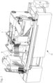
- Figure 1 shows the mold closing unit F of an injection molding machine 10.
- the drive of the mold closing unit can be seen on the right-hand side.
- two mold halves of an injection mold M are arranged between mold carriers of the mold closing unit F.
- the injection molding unit adjoining the mold closing unit F on the left is not shown in the drawing.
- a plasticizable mass is plasticized and homogenized in the injection molding unit so that it can then be injected by the injection molding unit into a mold cavity of the injection mold M. While the plasticizable mass is liquid or at least pasty during injection as a result of the plasticization, it then cools down in the injection mold M. After cooling down, the injection molded part produced in this way is ejected from the injection mold M.
- Tempering i.e. heating and subsequent cooling of the injection mold M is required, which is carried out via a tempering device 18.
- the tempering medium is supplied via the tempering device 18 via the Fig. 1 recognizable lines to the mold halves of the injection mold M.
- a wide variety of materials can be processed with an injection molding machine. As a rule, such a plastic injection molding machine 10 is intended and suitable for processing plastics and other plasticizable masses, such as metallic, ceramic and/or powdery masses.
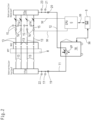
- the device comprises a machine control S. Temperature control medium is supplied to the injection mold M via at least one supply pump VP, which in the exemplary embodiment is arranged in the temperature control device 18.
- the device has at least one feed line 11, via which temperature control medium reaches the injection mold M from the supply pump VP.
- the feed line 11 comprises a pipe distributor 11a in addition to a line.
- a pipe distributor 12a which is however assigned to the return line 12, through which the tempering medium is discharged from the injection mold M at least indirectly to the supply pump VP.
- the tempering medium can be Fig. 2
- the temperature control medium can either be fed directly to the temperature control device 18, but it is also possible to feed the temperature control medium to a temperature control medium container, from which the supply pump VP pumps the temperature control medium back into the temperature control circuit via the feed line 11.
- tempering channels 13 are provided, which are guided through the injection mold M and are in fluid communication with the flow 11 and the return 12 or the corresponding pipe distributors 11a and 12a.
- adjustable flow rate valves 14 are provided in the tempering channels 13 for controlling/regulating the flow rate of tempering medium in the respective tempering channels 13.
- temperature sensors 15 are provided for detecting a temperature in the respective tempering channels 13 after flowing through and thus downstream of the injection mold M.
- flow meters 16 for detecting a flow rate in the respective tempering channels 13.
- the device comprises a control device C, which in Fig. 2 schematically indicated with the adjustable flow rate valves 14, the temperature sensors 15 and the flow meters 16 is connected in a control-technical manner and is set up to control and monitor the temperature, temperature difference to the flow, flow rate and/or dissipated heat output in the tempering channels 13. It is operatively connected to the machine control S.
- This is shown schematically for a tempering channel 13 as an example in Fig. 3
- the regulation of these variables is carried out by means of the flow rate valves 14 by controlling the flow rate of tempering medium in the tempering channels 13, whereby, for example, the target temperature can be quite different from tempering channel 13 to tempering channel 13.
- the flow rate valves 14, the temperature sensors 15 and the flow meters 16 are thus preferably each connected to one and/or a common control device which is designed to control and monitor the temperature of the tempering channels 13.
- Fig. 2 shows that the tempering channels 13 branch off from a common flow line 11 and end in a common return line 12.
- a flow temperature sensor 17 is provided in the flow line 11. If required, a flow meter 19 for the flow line and/or a pressure sensor 22 can also be provided there.
- the control device C is in operative connection with the machine control S to adjust the delivery rate of the adjustable supply pump VP to the demand for the flow rates of tempering medium in the tempering channels 13, which are regulated by the flow rate valves 14.
- Such a structure makes it possible, on the one hand, to "drive" different temperatures from one tempering channel 13 to the next, since the respective flow rate valves 14 control the flow rate of the respective tempering channel 13. supplied flow rate and thus also the dissipated heat flow (dissipated power) can be regulated.
- the temperature difference between the flow, measured at the flow temperature sensor 17, and the temperature sensors 15 in the return line is used for this purpose.
- this information can be passed on to the machine control S or preferably to a further control device C2 provided in the machine control S, which is connected to the temperature control device 18 depending on the known requirements of the temperature control device in order to adapt the flow rate of the supply pump VP to the respective requirements of the temperature control circuits or to track them.
- the further control device C2 thus forms a type of energy consumption controller. This not only enables individual temperature control within the injection mold M, but also ensures energy-efficient adjustment of the flow rate using the adjustable supply pump VP. This means that the energy requirement of the injection molding machine 10 can be adapted to the specific requirements from cycle to cycle and thus reduced.
- the control device C for controlling the flow rate controlled by the flow rate valves 14 is superimposed on the further control device C2 for controlling the delivery rate of the controllable supply pump VP.
- the machine control S or the further control device C2 is thus a second-order observer that can track the delivery rate as needed and in a timely manner as a type of energy consumption controller. This enables good adaptation to the respective temperature control power requirement for each temperature control channel 13, while at the same time the supply pump VP can be brought to an energy-efficient operating point by the observer on the higher-level machine control or the further control device C2 by specifying the manipulated variable speed and/or the flow pressure and/or the flow temperature, in which the delivery rate currently required is made available for all temperature control channels 13.
- the tracking of the supply pump VP is carried out using complex control algorithms (e.g. using neural networks), since the presence of many (typically e.g. 4 to 16) tempering channels 13 in an injection mold M results in a multi-dimensional, multi-variable control system. If the observer on the machine control or the additional control device C2 determines that the quantity control of the supply pump VP is no longer sufficient to satisfy the control requirements of the individual tempering channels 13 (e.g. if the quantity control of the supply pump VP is constantly running at 100% and thus under full load and the individual tempering channels 13 are constantly exceeding their target temperature), the higher-level observer on the machine control or the additional control device C2 can also intervene in the control of the flow temperature of the tempering supply of the subordinate individual tempering channels.
- complex control algorithms e.g. using neural networks
- the control working range of the higher-level observer on the machine control or the additional control device C2 is always selected so that the temperature control arrangement works as close to an energetic optimum as possible.
- the basic principle is that many temperature control channels 13 are provided, each of which is controlled either by a single controller or as in Fig. 2 shown a common control device C independently attempt to regulate their given control task in relation to either volume flow, temperature on the return line (with minimum volume flow to be maintained), temperature difference between flow and return, dissipated heat output (delta T * volume flow) by means of the actuator flow rate valve 14.
- the individual temperature control channels 13 are restricted in their control behavior by the given boundary conditions regarding flow supply and residual pressure in the return line by the (in principle self-sufficient) central temperature control device 18.
- the central temperature control device 18 now has, in addition to the usual variables such as flow temperature and flow pressure, an additional control variable for the pump speed of the supply pump, which is accessible via the control system. VP.
- the interaction between pump speed, resulting supply pressure in interaction with the current total consumption via the individual (consumer) temperature control channels 13 enables the second-order observer on the machine control or the further control device C2 to calculate/regulate an energy-optimal operating point for the entire system, whereby the main control variable is preferably the pump speed of the supply pump VP.
- control device C and higher-level observer in the form of the further control device C2 also has the advantage that any device can be integrated as the temperature control device 18, independently of the manufacturer and the control system.
- the flow rate valves 14 are arranged in the tempering channels 13 downstream of the flow through the injection mold M in order to eliminate the influence of the flow rate valves 14 on the energy balance. If a heat loss is generated at this point, which is preferably also downstream of the temperature sensors 15 and the flow meter 16, when flowing through the flow rate valves 14, this is not included in the control loop. As in Fig. 2 As shown schematically, the temperature sensors 15 are mounted downstream on the tempering channels 13 outside the injection mold M. For example, when controlling the temperature, a minimum flow rate must be maintained on the tempering channel 13 in order not to interrupt the effective connection to the actual tempering channel 13 in the mold.
- a further flow meter 20 as well as a temperature sensor 21 for the return line and a pressure sensor 23 may be provided.
- Other sensors such as flow meters and temperature sensors at other points in the circuit may also be provided.
- the information from these sensors may also be fed to the control device C or the further control device C2 or the machine control S for further use.
- These additional sensors enable an improvement in the stability of the further control device C2 as an energy consumption controller while maintaining the control quality for the individual temperature control channels.
- all control lines between the parts of the sensor system and the control device or the associated actuators such as the adjustable flow rate valves 14 are designed as analog and/or digital real-time connections and are connected to one another, for example via Ethernet. This means that timely, needs-based tracking is possible at any time.
- FIG. 3 An example of the data-technical connection between the parts of the entire temperature control arrangement is shown Fig. 3 schematically for a tempering channel 13 branching off from the pipe distributor 11a and opening into the pipe distributor 12a with flow rate valve 14, flow meter 16 and temperature sensor 15. All of these elements are connected to the control device C via the data and/or control lines 30, 31, 32.
- the control device C is operatively connected to the further control device C2 via the data line 35 and this is operatively connected to the tempering unit 18 via the data line 36.
- the further control device C2 is also operatively connected to the further sensors in the flow 11 and return 12 via the further data and control lines 41, 42, 43, 44, 45, 46.
- the flow temperature control of the injection mold M is operated with the described device in such a way that the temperature is initially controlled in a known manner via flow rate valves 14 provided in each temperature control channel 13, via which the flow of temperature control medium is controlled.
- the device makes use of the temperature difference between the flow 11, recorded by the flow temperature sensor 17, and the return 12 of the respective temperature control channel 13, recorded by the temperature sensors 15 in the return 12, in conjunction with the flow rate recorded by the flow meters 16.
- the control device C can calculate the heat flow, which can be used as a reference variable for controlling the temperature. Since the flow rate is also known by the flow meter 16, the flow rate of the adjustable supply pump VP can also be adapted to the specific requirement, which results from the flow rate controlled by the flow rate valves 14. This enables energy-efficient operation of the temperature control device.
- the actual volume flows known through the temperature control channels 13 can preferably be added up to form a total requirement.
- the delivery rate of the supply pump VP can be adapted to this total requirement in an energy-efficient manner.
Landscapes
- Engineering & Computer Science (AREA)
- Manufacturing & Machinery (AREA)
- Mechanical Engineering (AREA)
- Injection Moulding Of Plastics Or The Like (AREA)
- Moulds For Moulding Plastics Or The Like (AREA)
Claims (6)
- Machine de moulage par injection (10) pour la transformation de matières plastiques et d'autres masses plastifiables, comme des masses métalliques, céramiques et/ou pulvérulentes, avec un dispositif pour le réglage de la température de l'écoulement d'un moule de moulage par injection (M) comportant- une unité de commande de la machine (S),- au moins une pompe d'alimentation (VP) pour l'apport d'un milieu de réglage de la température au moule de moulage par injection (M),- un départ (11) par l'intermédiaire duquel le milieu de réglage de la température provenant de la pompe d'alimentation (VP) arrive au moule de moulage par injection (M),- un retour (12) par l'intermédiaire duquel le milieu de réglage de la température est transféré du moule de moulage par injection (M) au moins indirectement à la pompe d'alimentation (VP),- plusieurs canaux de réglage de la température (13), qui sont prévus à travers le moule de moulage par injection (M) et qui sont en liaison fluidique avec le départ (11) et le retour (12),- plusieurs vannes de débit réglables (14) pour le réglage du débit du médium de réglage de la température dans les canaux de réglage de la température (13) respectifs,- plusieurs capteurs de température (15) pour mesurer la température du milieu de réglage de la température dans les canaux de réglage de la température (13) respectifs,- plusieurs débitmètres (16) pour la mesure du débit du milieu de réglage de la température dans les canaux de réglage de la température respectifs (13),- les vannes de débit réglables (14), les capteurs de température (15) et les débitmètres (16) étant reliés à un circuit de réglage (C) qui est configuré pour régler et surveiller la température du milieu de réglage de la température dans les canaux de réglage de la température (13) et qui est en liaison active avec l'unité de commande de la machine (S), le réglage de la température se produisant grâce à la commande du débit de milieu de réglage de la température dans les canaux de réglage de la température (13),- les canaux de réglage de la température (13) dérivant du départ (11) qui leur est commun et dans lequel un capteur de température de départ (17) est prévu, et- les canaux de réglage de la température (13) aboutissant dans le retour (12) qui leur est commun etcette machine étant caractérisée en ce que le circuit de réglage (C) est en liaison active avec l'unité de commande de la machine (S) pour le suivi du débit de la pompe d'alimentation (VP) réglable selon le besoin en débit réglé par les vannes de débit réglable (14) eten ce que l'unité de commande de la machine (S) est configurée pour sélectionner au moyen d'algorithmes complexes, en particulier de réseaux neuronaux, un domaine de travail de réglage énergétiquement optimal dans un système de réglage à plusieurs grandeurs multidimensionnelles pour le suivi du débit de la pompe d'alimentation (VP) réglable.
- Dispositif selon la revendication 1, caractérisé en ce que sur le circuit de réglage (C) est superposé, pour le réglage du débit réglé par les vannes de réglage de débit (14), un autre circuit de réglage (C2) pour le réglage du débit à la pompe d'alimentation réglable (VP).
- Dispositif selon la revendication 1 ou 2, caractérisé en ce que les vannes de débit (14) sont disposées dans les canaux de réglage de la température en aval de l'écoulement à travers le moule de moulage par injection (M).
- Dispositif selon l'une ou plusieurs des revendications précédentes, caractérisé en ce que le circuit de réglage (C), les vannes de débit (14), les capteurs de température (15) et les débitmètres (16) sont en liaison active par l'intermédiaire d'une liaison en temps réel les uns avec les autres et/ou avec l'unité de commande de la machine (5).
- Procédé de réglage de la température d'un écoulement d'un moule de moulage par injection (M) avec un dispositif d'une machine de moulage par injection (10) selon l'une des revendications 1 à 4, dans lequel le réglage de la température s'effectue au moyen de vannes de réglage de débit (14) prévues dans chaque canal de réglage de la température (13), grâce auxquelles est réglé l'écoulement d'un milieu de réglage de la température à travers le canal de réglage de la température (13) respectif, la différence de température entre le départ (11) et le retour (12) du canal de réglage de la température (13) respectif ainsi que le débit étant mesurés dans le canal de réglage de la température (13) respectif et utilisés ensemble comme valeurs de référence pour le réglage de la température,ce procédé étant caractérisé en ce que le débit d'une pompe d'alimentation (VP) nécessaire pour le réglage de la température est suivi à travers les vannes de débit (14),un domaine de travail de réglage énergétiquement optimal étant sélectionné au moyen d'algorithmes complexes, en particulier de réseaux neuronaux, dans un système de réglage à plusieurs grandeurs multidimensionnelles pour le suivi du débit de la pompe d'alimentation (VP).
- Procédé selon la revendication 5, caractérisé en ce qu'en cas de demande nécessaire pour une réglage de débit volumétrique ou d'un réglage de quantité de chaleur, demande qui est connue par calcul par l'unité de commande de la machine (S) suite à la mesure par les capteurs de température (15) et les débitmètres (16), les débits volumétriques réels ainsi connus s'ajoutent à travers les canaux de réglage de la température (13) en un besoin global auquel le débit de la pompe d'alimentation (VP) s'adapte.
Applications Claiming Priority (1)
| Application Number | Priority Date | Filing Date | Title |
|---|---|---|---|
| DE102021104375.1A DE102021104375A1 (de) | 2021-02-24 | 2021-02-24 | Vorrichtung und Verfahren zur geregelten Durchflusstemperierung einer Spritzgießform |
Publications (3)
| Publication Number | Publication Date |
|---|---|
| EP4049825A1 EP4049825A1 (fr) | 2022-08-31 |
| EP4049825C0 EP4049825C0 (fr) | 2024-12-25 |
| EP4049825B1 true EP4049825B1 (fr) | 2024-12-25 |
Family
ID=80775122
Family Applications (1)
| Application Number | Title | Priority Date | Filing Date |
|---|---|---|---|
| EP22157475.9A Active EP4049825B1 (fr) | 2021-02-24 | 2022-02-18 | Dispositif et procédé de régulation de la température de l'écoulement d'un moule de moulage par injection |
Country Status (2)
| Country | Link |
|---|---|
| EP (1) | EP4049825B1 (fr) |
| DE (1) | DE102021104375A1 (fr) |
Family Cites Families (8)
| Publication number | Priority date | Publication date | Assignee | Title |
|---|---|---|---|---|
| DE102005019890B3 (de) | 2005-04-29 | 2006-11-30 | Dietmar Hofmann | Vorrichtung und Verfahren zur Temperierung von Formwerkzeugen |
| DE102010045900A1 (de) | 2010-09-17 | 2012-03-22 | Kraussmaffei Technologies Gmbh | Verfahren zur Herstellung eines Kunststoff-Formteils |
| EP2602085B1 (fr) | 2011-12-08 | 2015-11-25 | Wenz Kunststoff GmbH & Co. KG | Dispositif et procédé destinés à la régulation du débit d'un outil de moulage par injection |
| AT513042B1 (de) | 2012-12-21 | 2014-01-15 | Engel Austria Gmbh | Vorrichtung zur Temperiermedienversorgung und Verfahren zur Überwachung derselben |
| AT513870B1 (de) * | 2013-02-04 | 2014-12-15 | Engel Austria Gmbh | Verfahren zur Temperierung eines Formwerkzeugs |
| AT515948B1 (de) | 2014-07-03 | 2016-01-15 | Engel Austria Gmbh | Verfahren und Vorrichtung zur Temperierung eines Formwerkzeugs |
| AT517592B1 (de) * | 2015-11-27 | 2017-03-15 | Engel Austria Gmbh | Temperiervorrichtung |
| AT519157B1 (de) | 2016-10-14 | 2018-06-15 | Engel Austria Gmbh | Verfahren zum Auffinden einer Soll-Förderleistung eines Pumpensystems |
-
2021
- 2021-02-24 DE DE102021104375.1A patent/DE102021104375A1/de not_active Withdrawn
-
2022
- 2022-02-18 EP EP22157475.9A patent/EP4049825B1/fr active Active
Also Published As
| Publication number | Publication date |
|---|---|
| EP4049825C0 (fr) | 2024-12-25 |
| DE102021104375A1 (de) | 2022-08-25 |
| EP4049825A1 (fr) | 2022-08-31 |
Similar Documents
| Publication | Publication Date | Title |
|---|---|---|
| AT403856B (de) | Verfahren zum temperieren einer spritzgiessform | |
| DE112008001188B4 (de) | Spritzgussmaschinensystem | |
| EP0909628B1 (fr) | Méthode et dispositif pour le réglage du chauffage du canal d'injection d'un moule à cavités multiples | |
| DE69726366T2 (de) | Form mit schnellem Zyklus auf Anfrage | |
| AT518410B1 (de) | Reguliersystem | |
| EP2762291B1 (fr) | Dispositif et procédé de thermorégulation d'un outil de formage ou d'un composant d'une machine de formage | |
| DE102005019890B3 (de) | Vorrichtung und Verfahren zur Temperierung von Formwerkzeugen | |
| AT520890B1 (de) | Temperiergerät und Verfahren zum Steuern und Regeln eines Temperiergeräts für ein | |
| AT516167B1 (de) | Temperiervorrichtung zum variothermen oder konventionellen Temperieren von Formwerkzeugen | |
| EP4217182B1 (fr) | Procédé et appareil de fabrication additive d'un produit | |
| DE102018108106B4 (de) | Verfahren zum Regeln einer Temperatur einer Spritzgießmaschine und Regelsystem | |
| WO2019025087A1 (fr) | Dispositif et procédé de fabrication d'une pièce en mousse particulaire | |
| EP3698937B1 (fr) | Procédé pour régler le remplissage d'au moins une cavité | |
| DE102007019389A1 (de) | Temperiersystem, Vorrichtung mit Temperiersystem und Verfahren zum Temperieren einer Vorrichtung sowie zur Herstellung der Vorrichtung | |
| EP4049825B1 (fr) | Dispositif et procédé de régulation de la température de l'écoulement d'un moule de moulage par injection | |
| EP4157606B1 (fr) | Dispositif hydraulique et procédé de régulation d'un dispositif hydraulique | |
| EP1212184B1 (fr) | Procede et dispositif pour l'equilibrage de temperature d'outils de formage de presses d'injection | |
| DE102004006162B4 (de) | Verfahren und Vorrichtung zur Temperierung eines Sprietzgießwerkzeugs | |
| DE102023118020A1 (de) | Plastifiziereinheit für eine Formgebungsmaschine | |
| EP2298530B1 (fr) | Dispositif et procédé destinés à tempérer un outil de moulage par injection | |
| WO2018071940A1 (fr) | Procédé et dispositif pour produire des profilés en matière plastique | |
| AT521443B1 (de) | Temperiergerät und Verfahren zum Steuern und Regeln eines Temperiergeräts für ein Verarbeitungsgerät, insbesondere eine Spritzgießmaschine | |
| DE3448047C2 (fr) | ||
| DE102011053125B4 (de) | Vorrichtung zur Kühlung von Werkzeugen von Kunststoffverarbeitungsmaschinen | |
| WO2019011873A1 (fr) | Procédé permettant de réguler la température d'un moule et système de régulation thermique |
Legal Events
| Date | Code | Title | Description |
|---|---|---|---|
| PUAI | Public reference made under article 153(3) epc to a published international application that has entered the european phase |
Free format text: ORIGINAL CODE: 0009012 |
|
| STAA | Information on the status of an ep patent application or granted ep patent |
Free format text: STATUS: THE APPLICATION HAS BEEN PUBLISHED |
|
| AK | Designated contracting states |
Kind code of ref document: A1 Designated state(s): AL AT BE BG CH CY CZ DE DK EE ES FI FR GB GR HR HU IE IS IT LI LT LU LV MC MK MT NL NO PL PT RO RS SE SI SK SM TR |
|
| STAA | Information on the status of an ep patent application or granted ep patent |
Free format text: STATUS: REQUEST FOR EXAMINATION WAS MADE |
|
| 17P | Request for examination filed |
Effective date: 20230228 |
|
| RBV | Designated contracting states (corrected) |
Designated state(s): AL AT BE BG CH CY CZ DE DK EE ES FI FR GB GR HR HU IE IS IT LI LT LU LV MC MK MT NL NO PL PT RO RS SE SI SK SM TR |
|
| GRAP | Despatch of communication of intention to grant a patent |
Free format text: ORIGINAL CODE: EPIDOSNIGR1 |
|
| STAA | Information on the status of an ep patent application or granted ep patent |
Free format text: STATUS: GRANT OF PATENT IS INTENDED |
|
| INTG | Intention to grant announced |
Effective date: 20240729 |
|
| GRAS | Grant fee paid |
Free format text: ORIGINAL CODE: EPIDOSNIGR3 |
|
| GRAA | (expected) grant |
Free format text: ORIGINAL CODE: 0009210 |
|
| STAA | Information on the status of an ep patent application or granted ep patent |
Free format text: STATUS: THE PATENT HAS BEEN GRANTED |
|
| AK | Designated contracting states |
Kind code of ref document: B1 Designated state(s): AL AT BE BG CH CY CZ DE DK EE ES FI FR GB GR HR HU IE IS IT LI LT LU LV MC MK MT NL NO PL PT RO RS SE SI SK SM TR |
|
| REG | Reference to a national code |
Ref country code: GB Ref legal event code: FG4D Free format text: NOT ENGLISH |
|
| REG | Reference to a national code |
Ref country code: CH Ref legal event code: EP |
|
| REG | Reference to a national code |
Ref country code: DE Ref legal event code: R096 Ref document number: 502022002465 Country of ref document: DE |
|
| REG | Reference to a national code |
Ref country code: IE Ref legal event code: FG4D Free format text: LANGUAGE OF EP DOCUMENT: GERMAN |
|
| U01 | Request for unitary effect filed |
Effective date: 20250107 |
|
| U07 | Unitary effect registered |
Designated state(s): AT BE BG DE DK EE FI FR IT LT LU LV MT NL PT RO SE SI Effective date: 20250115 |
|
| U20 | Renewal fee for the european patent with unitary effect paid |
Year of fee payment: 4 Effective date: 20250123 |
|
| PG25 | Lapsed in a contracting state [announced via postgrant information from national office to epo] |
Ref country code: HR Free format text: LAPSE BECAUSE OF FAILURE TO SUBMIT A TRANSLATION OF THE DESCRIPTION OR TO PAY THE FEE WITHIN THE PRESCRIBED TIME-LIMIT Effective date: 20241225 |
|
| PG25 | Lapsed in a contracting state [announced via postgrant information from national office to epo] |
Ref country code: NO Free format text: LAPSE BECAUSE OF FAILURE TO SUBMIT A TRANSLATION OF THE DESCRIPTION OR TO PAY THE FEE WITHIN THE PRESCRIBED TIME-LIMIT Effective date: 20250325 |
|
| PG25 | Lapsed in a contracting state [announced via postgrant information from national office to epo] |
Ref country code: GR Free format text: LAPSE BECAUSE OF FAILURE TO SUBMIT A TRANSLATION OF THE DESCRIPTION OR TO PAY THE FEE WITHIN THE PRESCRIBED TIME-LIMIT Effective date: 20250326 |
|
| PG25 | Lapsed in a contracting state [announced via postgrant information from national office to epo] |
Ref country code: RS Free format text: LAPSE BECAUSE OF FAILURE TO SUBMIT A TRANSLATION OF THE DESCRIPTION OR TO PAY THE FEE WITHIN THE PRESCRIBED TIME-LIMIT Effective date: 20250325 |
|
| PG25 | Lapsed in a contracting state [announced via postgrant information from national office to epo] |
Ref country code: SM Free format text: LAPSE BECAUSE OF FAILURE TO SUBMIT A TRANSLATION OF THE DESCRIPTION OR TO PAY THE FEE WITHIN THE PRESCRIBED TIME-LIMIT Effective date: 20241225 |
|
| PG25 | Lapsed in a contracting state [announced via postgrant information from national office to epo] |
Ref country code: PL Free format text: LAPSE BECAUSE OF FAILURE TO SUBMIT A TRANSLATION OF THE DESCRIPTION OR TO PAY THE FEE WITHIN THE PRESCRIBED TIME-LIMIT Effective date: 20241225 |
|
| PG25 | Lapsed in a contracting state [announced via postgrant information from national office to epo] |
Ref country code: ES Free format text: LAPSE BECAUSE OF FAILURE TO SUBMIT A TRANSLATION OF THE DESCRIPTION OR TO PAY THE FEE WITHIN THE PRESCRIBED TIME-LIMIT Effective date: 20241225 |
|
| PG25 | Lapsed in a contracting state [announced via postgrant information from national office to epo] |
Ref country code: IS Free format text: LAPSE BECAUSE OF FAILURE TO SUBMIT A TRANSLATION OF THE DESCRIPTION OR TO PAY THE FEE WITHIN THE PRESCRIBED TIME-LIMIT Effective date: 20250425 |
|
| PG25 | Lapsed in a contracting state [announced via postgrant information from national office to epo] |
Ref country code: SK Free format text: LAPSE BECAUSE OF FAILURE TO SUBMIT A TRANSLATION OF THE DESCRIPTION OR TO PAY THE FEE WITHIN THE PRESCRIBED TIME-LIMIT Effective date: 20241225 |
|
| PG25 | Lapsed in a contracting state [announced via postgrant information from national office to epo] |
Ref country code: CZ Free format text: LAPSE BECAUSE OF FAILURE TO SUBMIT A TRANSLATION OF THE DESCRIPTION OR TO PAY THE FEE WITHIN THE PRESCRIBED TIME-LIMIT Effective date: 20241225 |
|
| PG25 | Lapsed in a contracting state [announced via postgrant information from national office to epo] |
Ref country code: MC Free format text: LAPSE BECAUSE OF FAILURE TO SUBMIT A TRANSLATION OF THE DESCRIPTION OR TO PAY THE FEE WITHIN THE PRESCRIBED TIME-LIMIT Effective date: 20241225 |
|
| PLBE | No opposition filed within time limit |
Free format text: ORIGINAL CODE: 0009261 |
|
| STAA | Information on the status of an ep patent application or granted ep patent |
Free format text: STATUS: NO OPPOSITION FILED WITHIN TIME LIMIT |
|
| REG | Reference to a national code |
Ref country code: CH Ref legal event code: L10 Free format text: ST27 STATUS EVENT CODE: U-0-0-L10-L00 (AS PROVIDED BY THE NATIONAL OFFICE) Effective date: 20251105 |
|
| 26N | No opposition filed |
Effective date: 20250926 |
|
| PG25 | Lapsed in a contracting state [announced via postgrant information from national office to epo] |
Ref country code: IE Free format text: LAPSE BECAUSE OF NON-PAYMENT OF DUE FEES Effective date: 20250218 |
|
| REG | Reference to a national code |
Ref country code: CH Ref legal event code: U11 Free format text: ST27 STATUS EVENT CODE: U-0-0-U10-U11 (AS PROVIDED BY THE NATIONAL OFFICE) Effective date: 20260301 |
|
| U20 | Renewal fee for the european patent with unitary effect paid |
Year of fee payment: 5 Effective date: 20260212 |
|
| PGFP | Annual fee paid to national office [announced via postgrant information from national office to epo] |
Ref country code: GB Payment date: 20260219 Year of fee payment: 5 |
|
| PGFP | Annual fee paid to national office [announced via postgrant information from national office to epo] |
Ref country code: CH Payment date: 20260301 Year of fee payment: 5 |