EP4049836B1 - Bandanordnungsvorrichtung - Google Patents
Bandanordnungsvorrichtung Download PDFInfo
- Publication number
- EP4049836B1 EP4049836B1 EP22157873.5A EP22157873A EP4049836B1 EP 4049836 B1 EP4049836 B1 EP 4049836B1 EP 22157873 A EP22157873 A EP 22157873A EP 4049836 B1 EP4049836 B1 EP 4049836B1
- Authority
- EP
- European Patent Office
- Prior art keywords
- guide roller
- tape
- support portion
- roller units
- support
- Prior art date
- Legal status (The legal status is an assumption and is not a legal conclusion. Google has not performed a legal analysis and makes no representation as to the accuracy of the status listed.)
- Active
Links
Images



Classifications
-
- B—PERFORMING OPERATIONS; TRANSPORTING
- B29—WORKING OF PLASTICS; WORKING OF SUBSTANCES IN A PLASTIC STATE IN GENERAL
- B29C—SHAPING OR JOINING OF PLASTICS; SHAPING OF MATERIAL IN A PLASTIC STATE, NOT OTHERWISE PROVIDED FOR; AFTER-TREATMENT OF THE SHAPED PRODUCTS, e.g. REPAIRING
- B29C70/00—Shaping composites, i.e. plastics material comprising reinforcements, fillers or preformed parts, e.g. inserts
- B29C70/04—Shaping composites, i.e. plastics material comprising reinforcements, fillers or preformed parts, e.g. inserts comprising reinforcements only, e.g. self-reinforcing plastics
- B29C70/28—Shaping operations therefor
- B29C70/30—Shaping by lay-up, i.e. applying fibres, tape or broadsheet on a mould, former or core; Shaping by spray-up, i.e. spraying of fibres on a mould, former or core
- B29C70/38—Automated lay-up, e.g. using robots, laying filaments according to predetermined patterns
- B29C70/386—Automated tape laying [ATL]
- B29C70/388—Tape placement heads, e.g. component parts, details or accessories
Definitions
- the present disclosure relates to a tape arranging device for arranging tape materials.
- a composite material in which a resin (plastic) is combined with a fiber (fiber reinforced plastics (FRP)) is a material excellent in specific strength and specific rigidity. Therefore, the composite material is used as structural materials and the like in the fields of automobiles, aircrafts, and space.
- the composite material is produced by laminating prepregs, fibers impregnated with a resin, to form a laminate, and then hardening the resin as disclosed, for example, in Japanese Unexamined Patent Application Publication ( JP-A) No. 2011-093276 .
- JP 2020 059145 A discloses a prepreg tape laminating apparatus including a moving unit that relatively moves a laminating head unit with respect to a laminating area.
- the laminating head unit includes a plurality of tape laminated portions arranged in a laminating operation direction.
- the apparatus further comprises an adjustment portion for adjusting the position of the tape laminated portions in the width direction of a prepreg tape.
- AFP automated fiber placement
- the present disclosure relates to a tape arranging device.
- the tape arranging device includes guide roller units and a moving unit. Tape materials are capable of passing through the respective guide roller units. Each of the tape materials are configured with fibers impregnated with resin.
- the moving unit is configured to move the guide roller units and to change a distance between adjacent ones of the guide roller units. The adjacent ones of the guide roller units are adjacent to each other.
- a distance between center lines of adjacent tape materials is referred to as a "tape pitch" in a sheet configured with the tape materials arranged without a gap.
- a width of the tape material itself may also be changed. Therefore, it is desired to develop a technique of arranging tape materials without a gap even when the width of the tape material is changed.
- the present disclosure relates to a tape arranging device capable of arranging tape materials at any tape pitch.
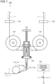
- FIG. 1 is a diagram illustrating a composite material manufacturing apparatus 100 according to the embodiments.
- the composite material manufacturing apparatus 100 includes a feeding device 110, heating devices 120, width adjusting devices 130, a tape arranging device 140, and a central control unit 150.
- an X axis, a Y axis, and a Z axis which perpendicular to each other are defined as shown with respect to the tape arranging device 140.
- a broken line arrow indicates a feeding direction of a tape material T by the feeding device 110.
- the feeding device 110 sends out the tape material T supplied from a stock roller or the like around which the tape material T is wound. In the embodiments, the feeding device 110 sends out seven tape materials T, but the number of tape materials T is not limited to seven.
- the tape material T is configured with prepregs. Prepregs are fibers impregnated with resin.
- the prepreg is used as a material of FRP (a composite material) such as CFRP or GFRP.
- the fibers configuring the tape material T are, for example, any one or more of carbon fibers, glass fibers, boron fibers, aramid fibers, and polyarylate fibers.
- Polyarylate fibers includes, for example, Vectran, which is a registered trademark.
- the resin configuring the tape material T is a thermosetting resin or a thermoplastic resin.
- thermosetting resin is, for example, any one or more of phenol resin (PF), epoxy resin (EP), melamine resin (MF), urea resin (UF), unsaturated polyester resin (UP), alkyd resin, polyurethane (PUR), thermosetting polyimide (PI), benzoxazine, and polybismaleimide (BMI).
- PF phenol resin
- EP epoxy resin
- MF melamine resin
- UF urea resin
- UP unsaturated polyester resin
- PUR thermosetting polyimide
- PI benzoxazine
- BMI polybismaleimide
- the thermoplastic resin is, for example, any one or more of polyphenylene sulfide (PPS), pre-tetrafluoroethylene, polysulfone (PSF), polyether sulfone (PES), amorphous polyarylate (PAR), liquid crystal polymer (LCP), polyether ether ketone (PEEK), thermoplastic polyimide (PI), polyamide imide (PAI), polyamide (PA), nylon, polyacetal (POM), polycarbonate (PC), modified polyphenylene ether (modified PPE), polyethylene terephthalate (PET), polybutylene terephthalate (PBT), cyclic polyolefin (COP), polyethylene (PE), polypropylene (PP), polyvinyl chloride (PVC), polyvinylidene chloride, polystyrene (PS), polyvinyl acetate (PVAc), polyurethane (PUR), ABS resin, AS resin, acrylic resin (PMMA), and polyetherketone ketone (PE
- the feeding device 110 includes a compaction roller 112, downstream support rollers 114a and 114b, and upstream support rollers 116a and 116b.
- the compaction roller 112, the downstream support rollers 114a and 114b, and the upstream support rollers 116a and 116b each have a cylindrical shape.
- the compaction roller 112, the downstream support rollers 114a and 114b, and the upstream support rollers 116a and 116b are arranged such that rotation axes thereof are in an X-axis direction in FIG. 1 .
- FIG. 2 is a perspective view of the tape arranging device 140.
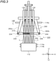
- FIG. 3 is a side view of the tape arranging device 140.
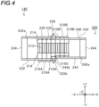
- FIG. 4 is a top view of the tape arranging device 140.
- guide roller units 210 are shown as guide roller units 210A to 210C.
- the guide roller units 210B are disposed on the second support portion 240 so as to be spaced apart from each other by the same distance r on a straight line with the shaft portion 250 as a center.
- the guide roller units 210A are disposed on the first support portion 230 so as to be spaced apart from each other by the same distance r on the straight line with the shaft portion 250 as a center.
- the tape pitch is a minimum tape pitch when the link unit 260 moves the tape materials T to pass through the guide roller units 210 disposed at the second position.
- the width adjustment device 130 adjusts the width of each tape material T according to a desired tape pitch.
- the tape arranging device 140 can easily change the tape pitch while maintaining the number of the tape materials T with a simple structure in which the first support portion 230 and the second support portion 240 are simply rotated. Therefore, the composite material manufacturing apparatus 100 including the tape arranging device 140 can easily mold a structure.
- the composite material manufacturing apparatus 100 including the tape arranging device 140 can also perform steering lamination in which the fibers are laminated while changing directions of the fibers.
- the guide roller unit 210 presses a surface of the tape material in order to change the tape pitch.
- the tape arranging device 140 can change the tape pitch while preventing damage to the tape material T, as compared with a case where the tape arranging device 140 presses the end portion of the tape material T.
- the tape arranging device 140 include the guide roller units 210, the first support portion 230, the second support portion 240, the shaft portion 250, and the link unit 260. Accordingly, the tape arranging device 140 can relatively reduce the moving distance of the tape material T located at a position close to the central tape material T and relatively increase the moving distance of the tape material T located at a position far from the central tape material T with a simple structure in which the first support portion 230 and the second support portion 240 are simply rotated. Therefore, the tape arranging device 140 facilitates control related to the change of the tape pitch. Further, the tape arranging device 140 is lower in cost than that of the comparative example.
- the upstream support roller 116a and the upstream support roller 116b have different positions in the Y-axis direction in FIG. 2 . Therefore, when the tape materials T enter the guide roller units 210, a situation in which the adjacent tape materials T come into contact with each other can be avoided.
- the tape material T has adhesiveness, and when the tape materials T are integrated by contact with each other, there is a concern that the tape materials T may not be bent at the time of lamination. Therefore, the positions of the downstream support roller 114a and the downstream support roller 114b in the Y-axis direction and the Z-axis direction in FIG. 2 are made different from each other. Accordingly, the situation in which the adjacent tape materials T sent out from the guide roller units 210 come into contact with each other and are not bent at the time of lamination can be avoided.
- the guide roller unit 210 may include one roller body 212.
- the guide roller unit 210 with which the tape material T is to be brought into contact is different between a case of increasing the tape pitch and a case of reducing the tape pitch.
- the other roller body 212 is unnecessary because the tape material T is always in contact with the roller body 212 on one side thereof.
- the tape arranging device 140 includes one shaft portion 250 .
- a plurality of shaft portions 250 may be provided. That is, the support portions may be moved into a W shape (or M shape) by the moving unit 220.
- the guide roller unit 210C is supported by the shaft portion 250 as an example.
- the guide roller unit 210C is not an essential component.
- the guide roller unit 210C may be omitted.
- the number of guide roller units 210A may be different from the number of guide roller units 210B.
- downstream support roller 114a and the downstream support roller 114b are provided to be different in positions in the Y-axis direction in FIG. 1 is described as an example.
- the positions of the downstream support roller 114a and the downstream support roller 114b may be the same.
- the downstream support roller 114a and the downstream support roller 114b may be replaced by a single roller.
- the upstream support roller 116a and the upstream support roller 116b are provided to be different in positions in the Y-axis direction in FIG. 1 is described as an example.
- the positions of the upstream support roller 116a and the upstream support roller 116b may be the same.
- the upstream support roller 116a and the upstream support roller 116b may be replaced by a single roller.
- the downstream support rollers 114a and 114b, and the upstream support rollers 116a and 116b are not essential components.
- the downstream support rollers 114a and 114b can be omitted by disposing the compaction roller 112 at a position substantially corresponding to the downstream support rollers 114a and 114b in place of the downstream support rollers 114a and 114b.
- the upstream support rollers 116a and 116b can also be omitted by changing a receiving direction of the tape material T and changing the path of the tape material T.
- the width adjustment device 130 is not an essential component.
- the width adjustment device 130 is not provided, only the tape pitch is adjusted without changing the tape width.
- a plurality of tape materials can be arranged at any tape pitch.
Landscapes
- Engineering & Computer Science (AREA)
- Robotics (AREA)
- Chemical & Material Sciences (AREA)
- Composite Materials (AREA)
- Mechanical Engineering (AREA)
- Moulding By Coating Moulds (AREA)
Claims (8)
- Bandanordnungsvorrichtung (140) aufweisend:Führungsrolleneinheiten (210), durch welche jeweils Bandmaterialien (T) passieren können, wobei jedes der Bandmaterialien mit Fasern, die mit Harz imprägniert sind, konfiguriert ist; undeine Bewegungseinheit (220), die konfiguriert ist, um die Führungsrolleneinheiten (210) in eine Längsrichtung der Bandmaterialien zu bewegen und einen Abstand zwischen angrenzenden der Führungsrolleneinheiten (210) zu ändern, wobei die angrenzenden der Führungsrolleneinheiten (210) aneinander angrenzend sind,wobei die Bewegungseinheit (220) aufweist:einen ersten und einen zweiten Trägerabschnitt (230, 240), die die Führungsrolleneinheiten (210) derart tragen, dass Rotationsachsen der Führungsrolleneinheiten (210) parallel zueinander sind,einen Wellenabschnitt (250), der einen Endabschnitt des ersten Trägerabschnitts (230) und einen Endabschnitt des zweiten Trägerabschnitts (240) rotierbar trägt, undeine Antriebseinheit (260), die konfiguriert ist, um den ersten Trägerabschnitt (230) und den zweiten Trägerabschnitt (240) zu rotieren.
- Bandanordnungsvorrichtung nach Anspruch 1,wobei der erste Trägerabschnitt (230) einen ersten Endabschnitt (232b) und einen dem ersten Endabschnitt (232b) gegenüberliegenden zweiten Endabschnitt (232a) aufweist, der zweite Trägerabschnitt (240) einen dritten Endabschnitt (242b) und einen dem dritten Endabschnitt (242b) gegenüberliegenden vierten Endabschnitt (242a) aufweist,wobei die angrenzenden der Führungsrolleneinheiten (210) erste Führungsrolleneinheiten (210A) und zweite Führungsrolleneinheiten (210B) aufweisen, wobei die ersten Führungsrolleneinheiten (210A) aneinander angrenzend sind, wobei die zweiten Führungsrolleneinheiten (210B) aneinander angrenzend sind,wobei der erste Trägerabschnitt (230) die ersten Führungsrolleneinheiten (210A) derart trägt, dass Rotationsachsen der ersten Führungsrolleneinheiten (210A) parallel zueinander sind,wobei der zweite Trägerabschnitt (240) die zweiten Führungsrolleneinheiten (210B) derart trägt, dass Rotationsachsen der zweiten Führungsrolleneinheiten (210B) parallel zueinander sind,wobei die von dem Wellenabschnitt (250) rotierbar getragenen Endabschnitte des ersten und zweiten Trägerabschnitts (230, 240) der erste Endabschnitt (232b) des ersten Trägerabschnitts (230) und der dritte Endabschnitt (242b) des zweiten Trägerabschnitts (240) sind, undwobei die Antriebseinheit (260) konfiguriert ist, um den ersten Trägerabschnitt (230) und den zweiten Trägerabschnitt (240) in eine Richtung zu rotieren, in welcher der zweite Endabschnitt (232a) des ersten Trägerabschnitts (230) und der vierte Endabschnitt (242a) des zweiten Trägerabschnitts (240) voneinander weg sind, oder in eine Richtung zu rotieren, in welcher der zweite Endabschnitt (232a) des ersten Trägerabschnitts (230) und der vierte Endabschnitt (242a) des zweiten Trägerabschnitts (240) sich einander nähern.
- Bandanordnungsvorrichtung nach Anspruch 1,wobei der erste Trägerabschnitt (230) einen ersten Endabschnitt (232b) und einen dem ersten Endabschnitt (232b) gegenüberliegenden zweiten Endabschnitt (232a) aufweist, wobei der zweite Trägerabschnitt (240) einen dritten Endabschnitt (242b) und einen dem dritten Endabschnitt (242b) gegenüberliegenden vierten Endabschnitt (242a) aufweist,wobei die Führungsrolleneinheiten (210) eine erste Führungsrolleneinheit (210A) und eine zweite Führungsrolleneinheit (210B) aufweisen,wobei der erste Trägerabschnitt (230) die erste Führungsrolleneinheit (210A) trägt,wobei der zweite Trägerabschnitt (240) die zweite Führungsrolleneinheit (210B) trägt,wobei von dem Wellenabschnitt (250) rotierbar getragenen Endabschnitte des ersten und zweiten Trägerabschnitts (230, 240) der erste Endabschnitt (232b) des ersten Trägerabschnitts (230) und der dritte Endabschnitt (242b) des zweiten Trägerabschnitts (240) sind, undwobei die Antriebseinheit (260) konfiguriert ist, um den ersten Trägerabschnitt (230) und den zweiten Trägerabschnitt (240) in eine Richtung zu rotieren, in welcher der zweite Endabschnitt (232a) des ersten Trägerabschnitts (230) und der vierte Endabschnitt (242a) des zweiten Trägerabschnitts (240) voneinander weg sind, oder in eine Richtung zu rotieren, in welcher der zweite Endabschnitt (232a) des ersten Trägerabschnitts (230) und der vierte Endabschnitt (242a) des zweiten Trägerabschnitts (240) sich einander nähern.
- Bandanordnungsvorrichtung nach einem der Ansprüche 1 bis 3,
wobei die Bewegungseinheit (220) konfiguriert ist, um die Führungsrolleneinheiten (210) zu bewegen, um Positionen der angrenzenden der Führungsrolleneinheiten (210) in eine Richtung zu ändern, in welcher die Bandmaterialien (T) die Führungsrolleneinheiten (210) passieren sollen. - Bandanordnungsvorrichtung nach Anspruch 2,
wobei jede der Führungsrolleneinheiten (210) aufweist:ein Paar Rollenkörper (212), undVerbindungsabschnitte (214), die konfiguriert sind, um das Paar Rollenkörper (212) rotierbar zu tragen, derart, dass Rotationsachsen des Paars Rollenkörper (212) zueinander parallel sind, undwobei die Verbindungsabschnitte (214) von dem ersten Trägerabschnitt (230) oder dem zweiten Trägerabschnitt (240) rotierbar getragen werden. - Bandanordnungsvorrichtung nach Anspruch 3,
wobei jede der Führungsrolleneinheiten (210) aufweist:ein Paar Rollenkörper (212), undVerbindungsabschnitte (214), die konfiguriert sind, um das Paar Rollenkörper (212) rotierbar zu tragen, derart, dass Rotationsachsen des Paars Rollenkörper (212) zueinander parallel sind, undwobei die Verbindungsabschnitte (214) von dem ersten Trägerabschnitt (230) oder dem zweiten Trägerabschnitt (240) rotierbar getragen werden. - Bandanordnungsvorrichtung nach Anspruch 5,
wobei die angrenzenden der Führungsrolleneinheiten (210) derart konfiguriert sind, dass die Rotationsachsen der Rollenkörper (212) der ersten Führungsrolleneinheiten (210A) parallel zu den Rotationsachsen der Rollenkörper (212) der zweiten Führungsrolleneinheiten (210B) sind. - Bandanordnungsvorrichtung nach Anspruch 6,
wobei die angrenzenden der Führungsrolleneinheiten (210) derart konfiguriert sind, dass die Rotationsachsen der Rollenkörper (212) der ersten Führungsrolleneinheit (210A) parallel zu den Rotationsachsen der Rollenkörper (212) der zweiten Führungsrolleneinheit (210B) sind.
Applications Claiming Priority (1)
| Application Number | Priority Date | Filing Date | Title |
|---|---|---|---|
| JP2021029124A JP7595484B2 (ja) | 2021-02-25 | 2021-02-25 | テープ配列機構 |
Publications (3)
| Publication Number | Publication Date |
|---|---|
| EP4049836A1 EP4049836A1 (de) | 2022-08-31 |
| EP4049836C0 EP4049836C0 (de) | 2025-02-26 |
| EP4049836B1 true EP4049836B1 (de) | 2025-02-26 |
Family
ID=80447181
Family Applications (1)
| Application Number | Title | Priority Date | Filing Date |
|---|---|---|---|
| EP22157873.5A Active EP4049836B1 (de) | 2021-02-25 | 2022-02-22 | Bandanordnungsvorrichtung |
Country Status (3)
| Country | Link |
|---|---|
| US (1) | US11919257B2 (de) |
| EP (1) | EP4049836B1 (de) |
| JP (1) | JP7595484B2 (de) |
Families Citing this family (6)
| Publication number | Priority date | Publication date | Assignee | Title |
|---|---|---|---|---|
| JP2024047485A (ja) | 2022-09-26 | 2024-04-05 | 株式会社Subaru | テープ送り出し用のローラユニット、繊維積層装置及び複合材成形方法 |
| JP2024047483A (ja) | 2022-09-26 | 2024-04-05 | 株式会社Subaru | テープ送り出し用のローラユニット、繊維積層装置及び複合材成形方法 |
| JP2024047484A (ja) | 2022-09-26 | 2024-04-05 | 株式会社Subaru | プリフォームの製造方法及び複合材成形方法 |
| JP2024128611A (ja) | 2023-03-10 | 2024-09-24 | 株式会社Subaru | 繊維積層装置及び複合材成形方法 |
| CN116766631B (zh) * | 2023-08-22 | 2023-11-03 | 太原理工大学 | 一种适应多宽度预浸带的双向铺带机械手及铺带方法 |
| JP2025101682A (ja) | 2023-12-25 | 2025-07-07 | 株式会社Subaru | 繊維の幅調整装置及び複合材成形方法 |
Family Cites Families (7)
| Publication number | Priority date | Publication date | Assignee | Title |
|---|---|---|---|---|
| DE102008016989A1 (de) | 2007-04-02 | 2008-10-09 | Cetex Institut für Textil- und Verarbeitungsmaschinen gemeinnützige GmbH | Verfahren und Vorrichtung zur partiellen Verstärkung einer Warenbahn |
| US8986482B2 (en) | 2008-07-08 | 2015-03-24 | The Boeing Company | Method and apparatus for producing composite structures |
| JP2011093276A (ja) | 2009-11-02 | 2011-05-12 | Toyota Motor Corp | フィラメントワインディングシステム、圧力容器の製造システム、圧力容器の製造方法 |
| JP6194909B2 (ja) * | 2015-03-10 | 2017-09-13 | トヨタ自動車株式会社 | フィラメントワインディング装置 |
| JP2017209902A (ja) | 2016-05-26 | 2017-11-30 | トヨタ自動車株式会社 | フィラメントワインディング装置 |
| CN112004660B (zh) | 2018-10-05 | 2023-06-06 | 福井县 | 薄层带自动层叠方法和装置 |
| JP6935621B2 (ja) | 2018-10-05 | 2021-09-15 | 福井県 | プリプレグテープの積層装置及び積層方法 |
-
2021
- 2021-02-25 JP JP2021029124A patent/JP7595484B2/ja active Active
-
2022
- 2022-02-11 US US17/669,870 patent/US11919257B2/en active Active
- 2022-02-22 EP EP22157873.5A patent/EP4049836B1/de active Active
Also Published As
| Publication number | Publication date |
|---|---|
| JP7595484B2 (ja) | 2024-12-06 |
| US11919257B2 (en) | 2024-03-05 |
| EP4049836C0 (de) | 2025-02-26 |
| EP4049836A1 (de) | 2022-08-31 |
| JP2022130133A (ja) | 2022-09-06 |
| US20220266545A1 (en) | 2022-08-25 |
Similar Documents
| Publication | Publication Date | Title |
|---|---|---|
| EP4049836A1 (de) | Bandanordnungsvorrichtung | |
| US11597168B2 (en) | Thin-layer tape automated lamination method and device | |
| KR101755015B1 (ko) | 헤드 유닛의 이동과, 형성 가능한 플라스틱 재료의 텐션 및 온도를 제어하는 트랜스포머 | |
| CN111479673B (zh) | 生产线和用于生产由纤维增强塑料制成的产品的方法 | |
| JP4874335B2 (ja) | Tfpプロセスによって所望表面形状を有する繊維構造プレフォームを製造する為の装置 | |
| WO2017150186A1 (ja) | 3次元プリンティング装置及び3次元プリンティング方法 | |
| KR20170085368A (ko) | 형성 가능한 플라스틱 재료로 이루어진 소재의 토출을 제어하는 헤드 유닛 및 헤드 서플라이 유닛 | |
| KR20160128004A (ko) | 형성 가능한 플라스틱 재료를 위한 3d 입체물 제조 로봇 | |
| JP4981801B2 (ja) | コンポジット部品のためのtfpプロセスによりファイバープリフォームを製造するための装置のための案内装置 | |
| CN102555230A (zh) | 树脂输送、施加和灌注系统与整体式铺层系统和使用方法 | |
| US12521945B2 (en) | Roller unit for feeding tapes, fiber placement apparatus and method of molding composite material | |
| US11141936B2 (en) | Fiber width adjusting apparatus, fiber width adjusting method, and composite forming method | |
| JP7526555B2 (ja) | プリプレグ積層装置及び複合材成形方法 | |
| US12194692B2 (en) | Fiber arranging device, method of arranging fibers and method of molding composite material | |
| CN107709645B (zh) | 纤维层叠体、纤维层叠体的制造方法以及纤维强化复合材料 | |
| EP3597414B1 (de) | Vorrichtungen und verfahren zur herstellung einer verbundstruktur und zur reaktion auf eine platzierungskraft | |
| JP4873879B2 (ja) | 多軸多層補強シートの製造方法及び製造装置 | |
| KR101957732B1 (ko) | 섬유강화플라스틱 소재 테이프를 이용한 프리폼 제조 장치 | |
| JP7495803B2 (ja) | 複合材製造装置 | |
| US20240100785A1 (en) | Roller unit for feeding tapes, fiber placement apparatus and method of molding composite material | |
| US20150130109A1 (en) | Method and device for producing a textile preform | |
| US11230072B2 (en) | Apparatuses for fabricating a composite structure and reacting to a placement force | |
| JP7547742B2 (ja) | 繊維強化基材の製造方法、繊維強化基材およびシャッター羽根の製造方法 | |
| CN110723271B (zh) | 用于制作复合结构并且对放置力起反作用的设备和方法 | |
| US20240198612A1 (en) | Forming device and forming method |
Legal Events
| Date | Code | Title | Description |
|---|---|---|---|
| PUAI | Public reference made under article 153(3) epc to a published international application that has entered the european phase |
Free format text: ORIGINAL CODE: 0009012 |
|
| STAA | Information on the status of an ep patent application or granted ep patent |
Free format text: STATUS: THE APPLICATION HAS BEEN PUBLISHED |
|
| AK | Designated contracting states |
Kind code of ref document: A1 Designated state(s): AL AT BE BG CH CY CZ DE DK EE ES FI FR GB GR HR HU IE IS IT LI LT LU LV MC MK MT NL NO PL PT RO RS SE SI SK SM TR |
|
| STAA | Information on the status of an ep patent application or granted ep patent |
Free format text: STATUS: REQUEST FOR EXAMINATION WAS MADE |
|
| 17P | Request for examination filed |
Effective date: 20230227 |
|
| RBV | Designated contracting states (corrected) |
Designated state(s): AL AT BE BG CH CY CZ DE DK EE ES FI FR GB GR HR HU IE IS IT LI LT LU LV MC MK MT NL NO PL PT RO RS SE SI SK SM TR |
|
| STAA | Information on the status of an ep patent application or granted ep patent |
Free format text: STATUS: EXAMINATION IS IN PROGRESS |
|
| 17Q | First examination report despatched |
Effective date: 20231122 |
|
| GRAP | Despatch of communication of intention to grant a patent |
Free format text: ORIGINAL CODE: EPIDOSNIGR1 |
|
| STAA | Information on the status of an ep patent application or granted ep patent |
Free format text: STATUS: GRANT OF PATENT IS INTENDED |
|
| INTG | Intention to grant announced |
Effective date: 20240917 |
|
| GRAS | Grant fee paid |
Free format text: ORIGINAL CODE: EPIDOSNIGR3 |
|
| GRAA | (expected) grant |
Free format text: ORIGINAL CODE: 0009210 |
|
| STAA | Information on the status of an ep patent application or granted ep patent |
Free format text: STATUS: THE PATENT HAS BEEN GRANTED |
|
| AK | Designated contracting states |
Kind code of ref document: B1 Designated state(s): AL AT BE BG CH CY CZ DE DK EE ES FI FR GB GR HR HU IE IS IT LI LT LU LV MC MK MT NL NO PL PT RO RS SE SI SK SM TR |
|
| REG | Reference to a national code |
Ref country code: GB Ref legal event code: FG4D |
|
| REG | Reference to a national code |
Ref country code: CH Ref legal event code: EP |
|
| REG | Reference to a national code |
Ref country code: DE Ref legal event code: R096 Ref document number: 602022010967 Country of ref document: DE |
|
| REG | Reference to a national code |
Ref country code: IE Ref legal event code: FG4D |
|
| U01 | Request for unitary effect filed |
Effective date: 20250226 |
|
| U07 | Unitary effect registered |
Designated state(s): AT BE BG DE DK EE FI FR IT LT LU LV MT NL PT RO SE SI Effective date: 20250306 |
|
| PG25 | Lapsed in a contracting state [announced via postgrant information from national office to epo] |
Ref country code: RS Free format text: LAPSE BECAUSE OF FAILURE TO SUBMIT A TRANSLATION OF THE DESCRIPTION OR TO PAY THE FEE WITHIN THE PRESCRIBED TIME-LIMIT Effective date: 20250526 |
|
| PG25 | Lapsed in a contracting state [announced via postgrant information from national office to epo] |
Ref country code: PL Free format text: LAPSE BECAUSE OF FAILURE TO SUBMIT A TRANSLATION OF THE DESCRIPTION OR TO PAY THE FEE WITHIN THE PRESCRIBED TIME-LIMIT Effective date: 20250226 |
|
| PG25 | Lapsed in a contracting state [announced via postgrant information from national office to epo] |
Ref country code: ES Free format text: LAPSE BECAUSE OF FAILURE TO SUBMIT A TRANSLATION OF THE DESCRIPTION OR TO PAY THE FEE WITHIN THE PRESCRIBED TIME-LIMIT Effective date: 20250226 |
|
| PG25 | Lapsed in a contracting state [announced via postgrant information from national office to epo] |
Ref country code: NO Free format text: LAPSE BECAUSE OF FAILURE TO SUBMIT A TRANSLATION OF THE DESCRIPTION OR TO PAY THE FEE WITHIN THE PRESCRIBED TIME-LIMIT Effective date: 20250526 Ref country code: IS Free format text: LAPSE BECAUSE OF FAILURE TO SUBMIT A TRANSLATION OF THE DESCRIPTION OR TO PAY THE FEE WITHIN THE PRESCRIBED TIME-LIMIT Effective date: 20250626 |
|
| PG25 | Lapsed in a contracting state [announced via postgrant information from national office to epo] |
Ref country code: HR Free format text: LAPSE BECAUSE OF FAILURE TO SUBMIT A TRANSLATION OF THE DESCRIPTION OR TO PAY THE FEE WITHIN THE PRESCRIBED TIME-LIMIT Effective date: 20250226 |
|
| PG25 | Lapsed in a contracting state [announced via postgrant information from national office to epo] |
Ref country code: GR Free format text: LAPSE BECAUSE OF FAILURE TO SUBMIT A TRANSLATION OF THE DESCRIPTION OR TO PAY THE FEE WITHIN THE PRESCRIBED TIME-LIMIT Effective date: 20250527 |
|
| PG25 | Lapsed in a contracting state [announced via postgrant information from national office to epo] |
Ref country code: SM Free format text: LAPSE BECAUSE OF FAILURE TO SUBMIT A TRANSLATION OF THE DESCRIPTION OR TO PAY THE FEE WITHIN THE PRESCRIBED TIME-LIMIT Effective date: 20250226 |
|
| PG25 | Lapsed in a contracting state [announced via postgrant information from national office to epo] |
Ref country code: CZ Free format text: LAPSE BECAUSE OF FAILURE TO SUBMIT A TRANSLATION OF THE DESCRIPTION OR TO PAY THE FEE WITHIN THE PRESCRIBED TIME-LIMIT Effective date: 20250226 |
|
| PG25 | Lapsed in a contracting state [announced via postgrant information from national office to epo] |
Ref country code: SK Free format text: LAPSE BECAUSE OF FAILURE TO SUBMIT A TRANSLATION OF THE DESCRIPTION OR TO PAY THE FEE WITHIN THE PRESCRIBED TIME-LIMIT Effective date: 20250226 |
|
| PLBE | No opposition filed within time limit |
Free format text: ORIGINAL CODE: 0009261 |
|
| STAA | Information on the status of an ep patent application or granted ep patent |
Free format text: STATUS: NO OPPOSITION FILED WITHIN TIME LIMIT |
|
| 26N | No opposition filed |
Effective date: 20251127 |
|
| U20 | Renewal fee for the european patent with unitary effect paid |
Year of fee payment: 5 Effective date: 20260106 |