EP4049870A1 - Kipper, der mit einer planenvorrichtung ausgestattet ist - Google Patents
Kipper, der mit einer planenvorrichtung ausgestattet ist Download PDFInfo
- Publication number
- EP4049870A1 EP4049870A1 EP22157868.5A EP22157868A EP4049870A1 EP 4049870 A1 EP4049870 A1 EP 4049870A1 EP 22157868 A EP22157868 A EP 22157868A EP 4049870 A1 EP4049870 A1 EP 4049870A1
- Authority
- EP
- European Patent Office
- Prior art keywords
- tarpaulin
- bucket
- carriage
- longitudinal
- branches
- Prior art date
- Legal status (The legal status is an assumption and is not a legal conclusion. Google has not performed a legal analysis and makes no representation as to the accuracy of the status listed.)
- Withdrawn
Links
- 238000005096 rolling process Methods 0.000 claims description 9
- 244000000231 Sesamum indicum Species 0.000 description 5
- 235000003434 Sesamum indicum Nutrition 0.000 description 5
- 238000007373 indentation Methods 0.000 description 3
- 240000008042 Zea mays Species 0.000 description 1
- 230000000295 complement effect Effects 0.000 description 1
Images


Classifications
-
- B—PERFORMING OPERATIONS; TRANSPORTING
- B60—VEHICLES IN GENERAL
- B60J—WINDOWS, WINDSCREENS, NON-FIXED ROOFS, DOORS, OR SIMILAR DEVICES FOR VEHICLES; REMOVABLE EXTERNAL PROTECTIVE COVERINGS SPECIALLY ADAPTED FOR VEHICLES
- B60J7/00—Non-fixed roofs; Roofs with movable panels, e.g. rotary sunroofs
- B60J7/02—Non-fixed roofs; Roofs with movable panels, e.g. rotary sunroofs of sliding type, e.g. comprising guide shoes
- B60J7/06—Non-fixed roofs; Roofs with movable panels, e.g. rotary sunroofs of sliding type, e.g. comprising guide shoes with non-rigid element or elements
- B60J7/061—Non-fixed roofs; Roofs with movable panels, e.g. rotary sunroofs of sliding type, e.g. comprising guide shoes with non-rigid element or elements sliding and folding
- B60J7/062—Non-fixed roofs; Roofs with movable panels, e.g. rotary sunroofs of sliding type, e.g. comprising guide shoes with non-rigid element or elements sliding and folding for utility vehicles
Definitions
- the present invention relates to a skip equipped with a covering device.
- a skip generally has a parallelepipedal shape having a bottom and side walls which are perpendicular in pairs. Skips can be opened at their top and then require a tarpaulin system to protect the contents of the skip.
- a dumpster opens via its rear wall in the normal forward position of the dumpster, but can also open via one of the longitudinal walls, also called sides.
- the longitudinal tailboard can tilt outwards in order to open the dumpster.
- the skip can open both on its rear wall and on one of its longitudinal sides, we speak of a twin tipper.
- a tarpaulin moving device for a two-sided skip which comprises a tarpaulin drive bar as well as a movable guide rail and a fixed guide rail.
- the fixed guide rail is secured to the fixed sideboard while the mobile guide rail is secured to the tilting sideboard.
- the tarpaulin drive bar enables a tarp to be driven between a position where it completely uncovers the upper opening of the dumpster and a position in which it completely covers the upper opening of the dumpster.
- the tarpaulin is supported by a plurality of rods in the form of arches. Sliding elements are attached to the rods and have a shape complementary to the mobile guide rail, which allows the tarpaulin to be guided towards its deployed position.
- the tarpaulin is not guided on the side of the tilting side panel.
- This lack of guidance of the tarpaulin on the side of the tilting sideboard and the use of arch-shaped bars means that most of the mass of the device is supported by the guide rail carried by the sideboard opposite the tilting sideboard . This poses problems of mechanical strength of the device.
- the Applicant Company has therefore sought a solution to these problems in order to obtain a tarpaulin system making it possible to open the tipping side of a two-way tipper with the tarp in the deployed position covering the upper opening of the tipper while presenting a good mechanical behavior of the system.
- the Applicant Company has therefore developed a skip equipped with a tarpaulin system with asymmetrical guidance, the guidance of the tarpaulin being ensured on the side of the tilting side board by a wheel rolling on the upper edge of the side board and the tarp being supported by a plurality of scissors, which makes it possible not to weigh the mass of the system solely on the guide rail carried by the longitudinal sideboard opposite the tilting sideboard.
- the present invention relates to a container for the transport of goods, of parallelepiped shape open at its upper part, comprising a bottom with four side walls, namely two longitudinal side walls if the direction of advance is considered.
- the scissor frame may comprise a succession of parallelograms hinged together at a central point and is extended at each end by the two branches of a half-parallelogram.
- the branches of the parallelograms of the scissor frame can be arranged in the same plane.
- the central pivot points of the scissor frame can be raised relative to the side pivot points, giving the tarp a generally domed shape.
- the push cart can then present an inverted V shape to match the dome shape of the tarp.
- the branches of the half-parallelogram facing the upper transverse edge of the bucket can be fixed at each of their ends to a carriage capable of sliding on a support arranged on said upper transverse edge
- the branches of the half-parallelogram facing the carriage push can be fixed at each of their ends on a carriage able to slide on the push carriage, the sliding carriages associated with the upper transverse border and those associated with the push carriage being mounted to allow the simultaneous approach of all the branches of the scissor frame for the deployment of the tarpaulin, as well as their simultaneous spacing for the folding of the tarpaulin along the upper transverse edge.
- the control of the deployment and the bringing together of the branches of the scissor frame can be carried out by a system with cylinders, such as, for example, a system with hydraulic cylinders, a system with electric cylinders or a system with pneumatic cylinders.
- a system with cylinders such as, for example, a system with hydraulic cylinders, a system with electric cylinders or a system with pneumatic cylinders.
- each sliding carriage associated with the upper transverse border can be mounted a jack of said jack system.
- the pushing carriage may comprise, in the vicinity of at least one of its ends, a wheel capable of rolling on the corresponding upper longitudinal edge of the bucket.
- a longitudinal groove can be made in the vicinity of the upper longitudinal edge of the bucket opposite the tilting side wall, and the push carriage can then comprise, correspondingly, a wheel capable of sliding in said groove.
- the box 1 Open at its upper part, the box 1 is delimited by a rectangular flat bottom 2 and by four side walls perpendicular to the bottom 2, namely a front transverse wall 3, a rear transverse wall 4, and two longitudinal walls 5 and 6 (5 designating the right longitudinal wall and 6, the left longitudinal wall, which can also be called an opening side wall).
- the front transverse wall 3 is delimited on each of its vertical edges by a right vertical post 7 and a left vertical post 8.
- the rear transverse wall 4 is delimited on each of its vertical edges by a vertical post 9 and 10 respectively (9 designating the right rear post and 10, the left rear post).
- the two posts 7 and 9 are joined by the straight longitudinal wall 5, which is fixed and has on the outside in the vicinity of its upper edge, a longitudinal groove 11 whose role is indicated below.
- Each of the posts 8 and 10 comprises, at its upper part, in return towards the interior space of the bucket, a horizontal bar respectively 12 and 13 whose role is indicated below.
- the two posts 7 and 9 are joined by the left longitudinal wall 6, which is articulated at the bottom 2 along its lower longitudinal edge by hinges 14.
- the wall 6 has, along its upper edge 15 and from the angle with the transverse edge, an indentation 16, 17 respectively (16 designating the front indentation and 17 designating the rear indentation) so that in position closed ( Picture 8 ), the upper longitudinal edge 15 is located in alignment with the upper edges of the bars 12 and 13 respectively.
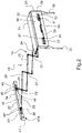
- the horizontal scissor frame 19 comprises a succession of three identical parallelograms 24, 25, 26, articulated at each of their vertices, with a common articulation 27, on the one hand, between the parallelogram front end 24 and the central parallelogram 25, and, on the other hand, between the central parallelogram 25 and the rear end parallelogram 26.
- the joints 28 of the two parallelograms 24 and 26 opposite the respective joints 27 are extended by the aforementioned branches 21 and 23 respectively, which each represent half-parallelograms.
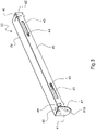
- the front member 20 consists of a vertical plate 29 intended to be placed transversely to overhang the front transverse edge of the opening of the bucket 1.
- This plate 29 extends downward along each of its side edges by an elongated tab 30 for attachment to a respective post.
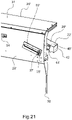
- the plate 29 is folded back, along its upper longitudinal edge, by a horizontal plate 31, called cap, the role of which is indicated below.
- the plate 29 carries towards the rear, projecting, a horizontal plate 32 which comes to be located under the cap 31, delimiting with the latter a space for receiving the tarpaulin B in the folded position ( Figure 8 ).
- openings 33 are each arranged in the vicinity of a side edge of the plate 29. Between the two openings 33 and on the outer wall (front wall) of the plate 29 is applied a plate 34 whose role is indicated below.
- each of the openings 33 is mounted a sliding carriage 35 which, at the rear, is connected to the corresponding branch of the front member 20 and which carries, projecting, a roller 36 with a vertical axis capable of rolling on the internal wall of the plate 29 above and below the respective oblong opening 33.
- the sliding carriage 35 carries projecting, in the same way as at the rear, a roller 37 of vertical axis able to roll on the external wall of the plate 29 above and below the respective oblong opening 33.
- the bodies of two cylinders 38 each able to move a rolling carriage 35 to cause it to slide in its corresponding oblong opening, the carriages 35 being able to be controlled to move away from one another. other in a position of maximum opening of the branches 21, folding on itself the scissor frame 19 ( Picture 8 ), or to approach each other in a position of minimum opening of the branches 21, deploying the scissor frame 19 ( Figure 1 for example).
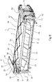
- the rear member 22 for fixing the two rear end branches 23 of the frame 19 consists of a push carriage comprising an elongated body delimited by a horizontal upper wall 39 of rectangular shape, by a front vertical transverse wall 40 connected by its upper edge to the rear edge of the wall 39, as well as a right vertical side wall 41 and a left vertical side wall 42, each being connected both to the horizontal upper edge of the wall 39 and to the vertical side edge of the wall 40.
- carriages 44 are each adapted to slide in an opening 43, each being connected, at the front, to a corresponding branch of the scissor frame 19. This sliding at the rear is, the same way as at the front, guided by vertical axis rollers 45.
- a device 46 capable of rolling on the corresponding upper longitudinal edge of the box 1, which has an inverted V profile on which rolling takes place.
- the associated device 46 which has, in the example shown, a diabolo-shaped roller for the device 46 on the left vertical wall 42 side and two rollers each in the shape of a diabolo for the device 46 on the right vertical wall 41 side.
- the straight vertical wall 41 is extended downwards by a triangular part 41a whose point is directed downwards. against this part 41a is fixed internally a horizontal axis around which is mounted a rotating roller 47, able to roll in the rail 11 ( Figures 10 to 12 ).
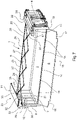
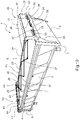
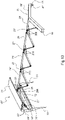
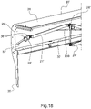
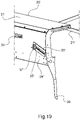
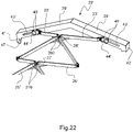
- FIG. 13 to 22 it can be seen that an alternative embodiment of the covering device has been shown in which the horizontal scissor frame 19 and the rear member 22 have been modified.
- the elements not modified with respect to the first embodiment carry the same reference numerals, and the modified elements the same reference numerals followed by “'”.
- Frame 19' is no longer flat but joints 27 and 28 are arranged in a plane lying above the other joints.
- Support rods 270 and 280 are placed below hinges 27' and 28' respectively. These support rods interconnect successive branches of neighboring parallelograms in order to follow the movement of the joints 27' and 28'.
- member 22' is also modified to have a general V shape.
- the oblong openings 33' and 43' are no longer horizontal but are inclined to be parallel to the corresponding average line of inclination of the member 22'.
Landscapes
- Engineering & Computer Science (AREA)
- Mechanical Engineering (AREA)
- Tents Or Canopies (AREA)
- Packaging Of Special Articles (AREA)
- Loading Or Unloading Of Vehicles (AREA)
Applications Claiming Priority (1)
| Application Number | Priority Date | Filing Date | Title |
|---|---|---|---|
| FR2101806A FR3120029B1 (fr) | 2021-02-24 | 2021-02-24 | Benne equipee d’un dispositif de bâchage |
Publications (1)
| Publication Number | Publication Date |
|---|---|
| EP4049870A1 true EP4049870A1 (de) | 2022-08-31 |
Family
ID=75278258
Family Applications (1)
| Application Number | Title | Priority Date | Filing Date |
|---|---|---|---|
| EP22157868.5A Withdrawn EP4049870A1 (de) | 2021-02-24 | 2022-02-22 | Kipper, der mit einer planenvorrichtung ausgestattet ist |
Country Status (2)
| Country | Link |
|---|---|
| EP (1) | EP4049870A1 (de) |
| FR (1) | FR3120029B1 (de) |
Citations (4)
| Publication number | Priority date | Publication date | Assignee | Title |
|---|---|---|---|---|
| JPS53102532A (en) * | 1976-09-25 | 1978-09-06 | Fumio Suzuki | Automatical hanger of seat for luggage carrier of truck |
| WO2004037581A1 (es) * | 2002-10-24 | 2004-05-06 | Ingenieria Diseño Y Analisis, S.L. | Bastidor extensible para lonas y toldos |
| FR2902379A1 (fr) | 2006-06-16 | 2007-12-21 | Equip Vehicules Ind E V I | Dispositif de deplacement de bache et benne avec un tel dispositif |
| FR3027568A1 (fr) | 2014-10-22 | 2016-04-29 | Equipements Vehicules Ind - E V I | Dispositif de deplacement de bache pour benne de vehicule utilitaire et benne munie d'un tel dispositif. |
-
2021
- 2021-02-24 FR FR2101806A patent/FR3120029B1/fr not_active Expired - Fee Related
-
2022
- 2022-02-22 EP EP22157868.5A patent/EP4049870A1/de not_active Withdrawn
Patent Citations (4)
| Publication number | Priority date | Publication date | Assignee | Title |
|---|---|---|---|---|
| JPS53102532A (en) * | 1976-09-25 | 1978-09-06 | Fumio Suzuki | Automatical hanger of seat for luggage carrier of truck |
| WO2004037581A1 (es) * | 2002-10-24 | 2004-05-06 | Ingenieria Diseño Y Analisis, S.L. | Bastidor extensible para lonas y toldos |
| FR2902379A1 (fr) | 2006-06-16 | 2007-12-21 | Equip Vehicules Ind E V I | Dispositif de deplacement de bache et benne avec un tel dispositif |
| FR3027568A1 (fr) | 2014-10-22 | 2016-04-29 | Equipements Vehicules Ind - E V I | Dispositif de deplacement de bache pour benne de vehicule utilitaire et benne munie d'un tel dispositif. |
Also Published As
| Publication number | Publication date |
|---|---|
| FR3120029B1 (fr) | 2024-08-09 |
| FR3120029A1 (fr) | 2022-08-26 |
Similar Documents
| Publication | Publication Date | Title |
|---|---|---|
| EP1215107B1 (de) | Kraftfahrzeug mit verlängbaren Ladepritschen | |
| FR2707236A1 (fr) | Agencement d'un capot arrière ou analogue sur un cadre de carrosserie d'un véhicule. | |
| FR2636219A1 (fr) | Agencement de meuble dans une construction et vehicule, tel que caravane, comprenant un meuble mobile | |
| EP3107747B1 (de) | Überdachungskonstruktion, insbesondere für eine ladeplattform, wie eine pritsche eines lastwagens, eine pritsche eines anhängers oder dergleichen, sowie überdachung mit solch einer struktur | |
| EP0584026A1 (de) | Kupplungseinheit zwischen zwei aufeinander folgenden Waggons und einem gemeinsamen Drehgestell | |
| CA2340016A1 (fr) | Structure arriere de support et de positionnement pour un ensemble routier articule de transport de voitures | |
| EP0586318B1 (de) | Umstellbarer, doppelter Boden für Kraftfahrzeuge in einer Transporteinheit | |
| EP4049870A1 (de) | Kipper, der mit einer planenvorrichtung ausgestattet ist | |
| EP3090927A1 (de) | Transportstruktur, die mit einer vertikalen schiebetür ausgestattet ist | |
| EP1775160B1 (de) | Verdeckaufbau für eine Fläche, insbesondere eine Ladefläche | |
| EP1765624B1 (de) | Öffnungsabdeckung eines kraftfahrzeugs, und fahrzeug mit einer solchen öffnungsabdeckung | |
| EP0741052B1 (de) | Gestell zur Abdeckung eines Nutzfahrzeuges mit einer bewegbaren Runge | |
| FR2493273A1 (fr) | Caisse de manutention et de stockage s'ouvrant en double porte sur sa face frontale | |
| FR2710019A1 (fr) | Caisse à parois latérales relevables pour véhicule de transport routier et véhicule équipé d'une telle caisse. | |
| FR3013272A1 (fr) | Abri roulant d'un nouveau type | |
| FR2653715A1 (fr) | Caisse a parois laterales relevables pour vehicule de transport routier et vehicule equipe d'une telle caisse. | |
| EP1093971A1 (de) | Lastenträger für ein Kraftfahrzeug und Kraftfahrzeug mit solchem Träger | |
| FR2940937A1 (fr) | Dispositif de support destine a faciliter le chargement d'un caisson ou d'un plateau sur une plate-forme | |
| FR2880842A1 (fr) | Porte laterale coulissante de vehicule automobile pourvue d'un marchepied embarque sur des moyens de support mobiles. | |
| WO2005080107A1 (fr) | Vehicule a toit decouvrable et hayon arriere | |
| EP1564053A1 (de) | Faltbares Hardtop für Fahrzeug | |
| EP1690715A1 (de) | Cabriolet-Fahrzeug, welches als Pick-Up konfiguriert werden kann | |
| EP1769961A2 (de) | In dem Kofferraum abstellbare Leichtbau-Dachstruktur | |
| NL8802795A (nl) | Afsluitbare laadbak. | |
| CH684693A5 (fr) | Rampe pour le chargement et le déchargement du plateau d'un véhicule de transport de marchandises. |
Legal Events
| Date | Code | Title | Description |
|---|---|---|---|
| PUAI | Public reference made under article 153(3) epc to a published international application that has entered the european phase |
Free format text: ORIGINAL CODE: 0009012 |
|
| STAA | Information on the status of an ep patent application or granted ep patent |
Free format text: STATUS: THE APPLICATION HAS BEEN PUBLISHED |
|
| AK | Designated contracting states |
Kind code of ref document: A1 Designated state(s): AL AT BE BG CH CY CZ DE DK EE ES FI FR GB GR HR HU IE IS IT LI LT LU LV MC MK MT NL NO PL PT RO RS SE SI SK SM TR |
|
| STAA | Information on the status of an ep patent application or granted ep patent |
Free format text: STATUS: REQUEST FOR EXAMINATION WAS MADE |
|
| 17P | Request for examination filed |
Effective date: 20221215 |
|
| RBV | Designated contracting states (corrected) |
Designated state(s): AL AT BE BG CH CY CZ DE DK EE ES FI FR GB GR HR HU IE IS IT LI LT LU LV MC MK MT NL NO PL PT RO RS SE SI SK SM TR |
|
| GRAP | Despatch of communication of intention to grant a patent |
Free format text: ORIGINAL CODE: EPIDOSNIGR1 |
|
| RIC1 | Information provided on ipc code assigned before grant |
Ipc: B60J 7/06 20060101AFI20230406BHEP |
|
| STAA | Information on the status of an ep patent application or granted ep patent |
Free format text: STATUS: GRANT OF PATENT IS INTENDED |
|
| INTG | Intention to grant announced |
Effective date: 20230511 |
|
| STAA | Information on the status of an ep patent application or granted ep patent |
Free format text: STATUS: THE APPLICATION IS DEEMED TO BE WITHDRAWN |
|
| 18D | Application deemed to be withdrawn |
Effective date: 20230922 |