EP4049882B1 - Procédé de surveillance de tension, procédé de surveillance de tension, et véhicule électrique - Google Patents
Procédé de surveillance de tension, procédé de surveillance de tension, et véhicule électrique Download PDFInfo
- Publication number
- EP4049882B1 EP4049882B1 EP22159017.7A EP22159017A EP4049882B1 EP 4049882 B1 EP4049882 B1 EP 4049882B1 EP 22159017 A EP22159017 A EP 22159017A EP 4049882 B1 EP4049882 B1 EP 4049882B1
- Authority
- EP
- European Patent Office
- Prior art keywords
- module
- voltage
- output voltage
- power conversion
- adc
- Prior art date
- Legal status (The legal status is an assumption and is not a legal conclusion. Google has not performed a legal analysis and makes no representation as to the accuracy of the status listed.)
- Active
Links
Images

Classifications
-
- B—PERFORMING OPERATIONS; TRANSPORTING
- B60—VEHICLES IN GENERAL
- B60L—PROPULSION OF ELECTRICALLY-PROPELLED VEHICLES; SUPPLYING ELECTRIC POWER FOR AUXILIARY EQUIPMENT OF ELECTRICALLY-PROPELLED VEHICLES; ELECTRODYNAMIC BRAKE SYSTEMS FOR VEHICLES IN GENERAL; MAGNETIC SUSPENSION OR LEVITATION FOR VEHICLES; MONITORING OPERATING VARIABLES OF ELECTRICALLY-PROPELLED VEHICLES; ELECTRIC SAFETY DEVICES FOR ELECTRICALLY-PROPELLED VEHICLES
- B60L58/00—Methods or circuit arrangements for monitoring or controlling batteries or fuel cells, specially adapted for electric vehicles
- B60L58/10—Methods or circuit arrangements for monitoring or controlling batteries or fuel cells, specially adapted for electric vehicles for monitoring or controlling batteries
- B60L58/12—Methods or circuit arrangements for monitoring or controlling batteries or fuel cells, specially adapted for electric vehicles for monitoring or controlling batteries responding to state of charge [SoC]
- B60L58/13—Maintaining the SoC within a determined range
-
- B—PERFORMING OPERATIONS; TRANSPORTING
- B60—VEHICLES IN GENERAL
- B60L—PROPULSION OF ELECTRICALLY-PROPELLED VEHICLES; SUPPLYING ELECTRIC POWER FOR AUXILIARY EQUIPMENT OF ELECTRICALLY-PROPELLED VEHICLES; ELECTRODYNAMIC BRAKE SYSTEMS FOR VEHICLES IN GENERAL; MAGNETIC SUSPENSION OR LEVITATION FOR VEHICLES; MONITORING OPERATING VARIABLES OF ELECTRICALLY-PROPELLED VEHICLES; ELECTRIC SAFETY DEVICES FOR ELECTRICALLY-PROPELLED VEHICLES
- B60L3/00—Electric devices on electrically-propelled vehicles for safety purposes; Monitoring operating variables, e.g. speed, deceleration or energy consumption
- B60L3/0023—Detecting, eliminating, remedying or compensating for drive train abnormalities, e.g. failures within the drive train
- B60L3/003—Detecting, eliminating, remedying or compensating for drive train abnormalities, e.g. failures within the drive train relating to inverters
-
- B—PERFORMING OPERATIONS; TRANSPORTING
- B60—VEHICLES IN GENERAL
- B60L—PROPULSION OF ELECTRICALLY-PROPELLED VEHICLES; SUPPLYING ELECTRIC POWER FOR AUXILIARY EQUIPMENT OF ELECTRICALLY-PROPELLED VEHICLES; ELECTRODYNAMIC BRAKE SYSTEMS FOR VEHICLES IN GENERAL; MAGNETIC SUSPENSION OR LEVITATION FOR VEHICLES; MONITORING OPERATING VARIABLES OF ELECTRICALLY-PROPELLED VEHICLES; ELECTRIC SAFETY DEVICES FOR ELECTRICALLY-PROPELLED VEHICLES
- B60L3/00—Electric devices on electrically-propelled vehicles for safety purposes; Monitoring operating variables, e.g. speed, deceleration or energy consumption
- B60L3/0023—Detecting, eliminating, remedying or compensating for drive train abnormalities, e.g. failures within the drive train
- B60L3/0046—Detecting, eliminating, remedying or compensating for drive train abnormalities, e.g. failures within the drive train relating to electric energy storage systems, e.g. batteries or capacitors
-
- B—PERFORMING OPERATIONS; TRANSPORTING
- B60—VEHICLES IN GENERAL
- B60L—PROPULSION OF ELECTRICALLY-PROPELLED VEHICLES; SUPPLYING ELECTRIC POWER FOR AUXILIARY EQUIPMENT OF ELECTRICALLY-PROPELLED VEHICLES; ELECTRODYNAMIC BRAKE SYSTEMS FOR VEHICLES IN GENERAL; MAGNETIC SUSPENSION OR LEVITATION FOR VEHICLES; MONITORING OPERATING VARIABLES OF ELECTRICALLY-PROPELLED VEHICLES; ELECTRIC SAFETY DEVICES FOR ELECTRICALLY-PROPELLED VEHICLES
- B60L3/00—Electric devices on electrically-propelled vehicles for safety purposes; Monitoring operating variables, e.g. speed, deceleration or energy consumption
- B60L3/04—Cutting off the power supply under fault conditions
-
- G—PHYSICS
- G01—MEASURING; TESTING
- G01R—MEASURING ELECTRIC VARIABLES; MEASURING MAGNETIC VARIABLES
- G01R19/00—Arrangements for measuring currents or voltages or for indicating presence or sign thereof
- G01R19/165—Indicating that current or voltage is either above or below a predetermined value or within or outside a predetermined range of values
- G01R19/16504—Indicating that current or voltage is either above or below a predetermined value or within or outside a predetermined range of values characterised by the components employed
-
- G—PHYSICS
- G01—MEASURING; TESTING
- G01R—MEASURING ELECTRIC VARIABLES; MEASURING MAGNETIC VARIABLES
- G01R19/00—Arrangements for measuring currents or voltages or for indicating presence or sign thereof
- G01R19/165—Indicating that current or voltage is either above or below a predetermined value or within or outside a predetermined range of values
- G01R19/16533—Indicating that current or voltage is either above or below a predetermined value or within or outside a predetermined range of values characterised by the application
- G01R19/16538—Indicating that current or voltage is either above or below a predetermined value or within or outside a predetermined range of values characterised by the application in AC or DC supplies
-
- G—PHYSICS
- G01—MEASURING; TESTING
- G01R—MEASURING ELECTRIC VARIABLES; MEASURING MAGNETIC VARIABLES
- G01R31/00—Arrangements for testing electric properties; Arrangements for locating electric faults; Arrangements for electrical testing characterised by what is being tested not provided for elsewhere
- G01R31/36—Arrangements for testing, measuring or monitoring the electrical condition of accumulators or electric batteries, e.g. capacity or state of charge [SoC]
- G01R31/382—Arrangements for monitoring battery or accumulator variables, e.g. SoC
- G01R31/3835—Arrangements for monitoring battery or accumulator variables, e.g. SoC involving only voltage measurements
-
- G—PHYSICS
- G01—MEASURING; TESTING
- G01R—MEASURING ELECTRIC VARIABLES; MEASURING MAGNETIC VARIABLES
- G01R31/00—Arrangements for testing electric properties; Arrangements for locating electric faults; Arrangements for electrical testing characterised by what is being tested not provided for elsewhere
- G01R31/40—Testing power supplies
-
- B—PERFORMING OPERATIONS; TRANSPORTING
- B60—VEHICLES IN GENERAL
- B60L—PROPULSION OF ELECTRICALLY-PROPELLED VEHICLES; SUPPLYING ELECTRIC POWER FOR AUXILIARY EQUIPMENT OF ELECTRICALLY-PROPELLED VEHICLES; ELECTRODYNAMIC BRAKE SYSTEMS FOR VEHICLES IN GENERAL; MAGNETIC SUSPENSION OR LEVITATION FOR VEHICLES; MONITORING OPERATING VARIABLES OF ELECTRICALLY-PROPELLED VEHICLES; ELECTRIC SAFETY DEVICES FOR ELECTRICALLY-PROPELLED VEHICLES
- B60L2240/00—Control parameters of input or output; Target parameters
- B60L2240/40—Drive Train control parameters
- B60L2240/52—Drive Train control parameters related to converters
- B60L2240/527—Voltage
-
- B—PERFORMING OPERATIONS; TRANSPORTING
- B60—VEHICLES IN GENERAL
- B60L—PROPULSION OF ELECTRICALLY-PROPELLED VEHICLES; SUPPLYING ELECTRIC POWER FOR AUXILIARY EQUIPMENT OF ELECTRICALLY-PROPELLED VEHICLES; ELECTRODYNAMIC BRAKE SYSTEMS FOR VEHICLES IN GENERAL; MAGNETIC SUSPENSION OR LEVITATION FOR VEHICLES; MONITORING OPERATING VARIABLES OF ELECTRICALLY-PROPELLED VEHICLES; ELECTRIC SAFETY DEVICES FOR ELECTRICALLY-PROPELLED VEHICLES
- B60L2240/00—Control parameters of input or output; Target parameters
- B60L2240/40—Drive Train control parameters
- B60L2240/54—Drive Train control parameters related to batteries
- B60L2240/547—Voltage
-
- G—PHYSICS
- G01—MEASURING; TESTING
- G01R—MEASURING ELECTRIC VARIABLES; MEASURING MAGNETIC VARIABLES
- G01R19/00—Arrangements for measuring currents or voltages or for indicating presence or sign thereof
- G01R19/165—Indicating that current or voltage is either above or below a predetermined value or within or outside a predetermined range of values
- G01R19/16566—Circuits and arrangements for comparing voltage or current with one or several thresholds and for indicating the result not covered by subgroups G01R19/16504, G01R19/16528, G01R19/16533
- G01R19/16576—Circuits and arrangements for comparing voltage or current with one or several thresholds and for indicating the result not covered by subgroups G01R19/16504, G01R19/16528, G01R19/16533 comparing DC or AC voltage with one threshold
Definitions
- This application relates to the field of electric vehicle technologies, and in particular, to a voltage monitoring method, a voltage monitoring apparatus, and an electric vehicle.
- a power supply as one of core components of each part of an electric vehicle, is vital for functional safety of the parts.
- Power supply exceptions include overvoltage, undervoltage, drifts, oscillation, and spikes. When one of the exceptions occurs, fast diagnosis and protection need to be performed. Otherwise, a cascading failure may easily occur, violating safety goals.
- a diagnostic mechanism in D.2.6.2 Voltage or current control (output) in ISO 26262-5 Annex D may be used, to monitor an output voltage of a power supply in real time.
- the mechanism can reach diagnostic coverage of 99% for a single-point fault metric of the power supply, thereby reaching a level of ASIL D.
- US2007223262A1 relates to multiple inverter system with single controller and related operating method.
- US2012280644A1 relates to inverter and a method for controlling an electric machine.
- US2013151181A1 relates to determining a battery chemistry for a battery in a peripheral device.
- US9234943B2 relates to method and system for battery current measurement calibration.
- An objective of this application is to provide a voltage monitoring method, a voltage monitoring apparatus, and an electric vehicle, to enable a power conversion module to reach a level of ASIL D.
- the voltage monitoring apparatus includes a power conversion module and a microcontroller electrically connected to the power conversion module.
- the power conversion module is configured to output a voltage.
- the microcontroller includes an ADC module, a monitoring module, and an IO module.
- the ADC module is configured to obtain an output voltage of the power conversion module, and determine whether the output voltage encounters an exception.
- the monitoring module is configured to: when the output voltage encounters an exception, output a control signal through the IO module.
- the power conversion module is further configured to stop outputting a voltage based on the control signal.
- diagnostic coverage can reach 99% for an SPFM of the output voltage of the power conversion module, thereby reaching a corresponding level of ASIL D.
- the microcontroller and its peripheral resources are used for implementation, integration can be improved, and BOM costs of an electric vehicle can be reduced, helping control costs of the entire vehicle.
- the exception includes overvoltage and undervoltage.
- the output voltage When the output voltage is higher than an upper voltage threshold, the output voltage encounters overvoltage.
- the output voltage When the output voltage is lower than a lower voltage threshold, the output voltage encounters undervoltage.
- the upper voltage threshold is greater than the lower voltage threshold.
- the microcontroller further includes a self-checking module, a PWM module, and a low-pass filter circuit.
- the self-checking module is configured to control a duty cycle of a voltage of the PWM module during power-on, so that the PWM module outputs an expected voltage.
- the expected voltage is transmitted to the ADC module after passing through the low-pass filter circuit, to diagnose whether the ADC module encounters an exception. It should be understood that through cooperation between structures such as the self-checking module, the PWM module, and the low-pass filter circuit, diagnostic coverage can reach 90% for an LFM, thereby reaching the corresponding level of ASIL D and guaranteeing functional safety for the power conversion module.
- the monitoring module is further configured to: when the output voltage encounters an exception, identify a power conversion module that encounters an exception, to correspondingly output the control signal. Therefore, the voltage monitoring apparatus can monitor output voltages of the plurality of power conversion modules. When an exception occurs, it is ensured that the electric vehicle enters a controllable safe state, guaranteeing personal safety for driving participants.
- the microcontroller further includes an external circuit, the external circuit is electrically connected between the ADC module and the power conversion module, and the output voltage is transmitted to the ADC module after passing through the external circuit.
- the external circuit is a bleeder circuit, to divide the output voltage of the power conversion module.
- the ADC module triggers an interrupt based on the expected voltage
- the monitoring module is configured to output the control signal to the power conversion module through the IO module during the interrupt, so that the power conversion module stops outputting a voltage, and the ADC module learns through monitoring that the output voltage encounters an exception.
- the ADC module is further configured to obtain a range of the output voltage during power-on, and the self-checking module is further configured to diagnose, based on the range of the output voltage, whether the ADC module fails.
- the ADC module has a comparator function, to monitor whether the output voltage encounters an exception, and to obtain the range of the output voltage during power-on. With the comparator function, the ADC module can directly perform fast comparison for the output voltage without switching between modes.
- the voltage monitoring apparatus is applied to an on-board charger or a motor control unit.
- the external circuit is a part of the microcontroller, whereas in some other implementations, the external circuit is located outside the microcontroller.
- This application further provides an electric vehicle, including the foregoing voltage monitoring apparatus.
- This application further provides a voltage monitoring method, applied to an electric vehicle.
- the method includes: An ADC module obtains an output voltage of a power conversion module. When the ADC module determines that the output voltage encounters an exception, a monitoring module outputs a control signal to the power conversion module through an IO module, where the exception includes overvoltage or undervoltage. Based on the control signal, the power conversion module is controlled to stop outputting a voltage. It should be understood that with the voltage monitoring method, diagnostic coverage can reach 99% for an SPFM of the output voltage of the power conversion module, thereby reaching a corresponding level of ASIL D. In addition, because a microcontroller and its peripheral resources are used for implementation, integration can be improved, and BOM costs of an electric vehicle can be reduced, helping control costs of the entire vehicle.
- the exception includes overvoltage and undervoltage.
- the output voltage When the output voltage is higher than an upper voltage threshold, the output voltage encounters overvoltage.
- the output voltage When the output voltage is lower than a lower voltage threshold, the output voltage encounters undervoltage.
- the upper voltage threshold is greater than the lower voltage threshold.
- the microcontroller further includes a self-checking module, a PWM module, and a low-pass filter circuit.
- the self-checking module is configured to control a duty cycle of a voltage of the PWM module during power-on, so that the PWM module outputs an expected voltage.
- the expected voltage is transmitted to the ADC module after passing through the low-pass filter circuit, to diagnose whether the ADC module encounters an exception. It should be understood that through cooperation between structures such as the self-checking module, the PWM module, and the low-pass filter circuit, diagnostic coverage can reach 90% for an LFM, thereby reaching the corresponding level of ASIL D and guaranteeing functional safety for the power conversion module.
- the method further includes: The monitoring module identifies a power conversion module that encounters an exception, to correspondingly output the control signal.
- the method before the ADC module obtains the output voltage of the power conversion module, the method further includes: A bleeder circuit divides and transmits the output voltage to the ADC module.
- the method further includes: The ADC module obtains a range of the output voltage during power-on; and the self-checking module diagnoses, based on the range of the output voltage, whether the ADC module and the bleeder circuit fail.
- the method further includes: A self-checking module controls a duty cycle of a voltage of a PWM module during power-on, so that the PWM module sends an expected voltage to the ADC module.
- the ADC module determines, based on the expected voltage, that the output voltage encounters an exception.
- the monitoring module outputs the control signal through the IO module. Based on the control signal, the power conversion module is controlled to stop outputting a voltage. Based on this, it can be ensured that diagnostic coverage can reach 90% or higher for an LFM, thereby meeting a requirement of the corresponding level of ASIL D and guaranteeing functional safety for the power conversion module.
- the microcontroller and its related peripheral resources are used, so that diagnostic coverage reaches 99% or higher for the SPFM of the voltage monitoring apparatus and 90% or higher for the LFM of the voltage monitoring apparatus, and a corresponding safety level can reach ASIL D, thereby ensuring driving safety for the electric vehicle.
- ASILs Automotive Safety Integration Levels
- Hardware architecture metrics include SPFM (Single-Point Fault Metric), LFM (Latent-Fault Metric), and PMHF (Probabilistic Metric for random Hardware Failures).
- Corresponding ASILs include ASIL A, ASIL B, ASIL C, and ASIL D. Table 1 ASIL B ASIL C ASIL D SPFM ⁇ 90% ⁇ 97% ⁇ 99% LFM ⁇ 60% ⁇ 80% ⁇ 90% PMHF ⁇ 10 -7 h -1 (100 FIT) ⁇ 10 -8 h -1 (100 FIT) ⁇ 10 -8 h -1 (10 FIT)
- Table 1 shows relationships between the ASILs and the SPFM, LFM, and PMHF. As shown in Table 1, different ASILs have different requirements for values of the SPFM, LFM, and PMHF. For example, ASIL D requires that diagnostic coverage reach 99% for the SPFM and 90% for the LFM, and less than 10 FIT for the PMHF.
- an output voltage of a power conversion module needs to be monitored in real time, to determine whether the power conversion module fails.
- some measures need to be taken, to ensure that the entire electric vehicle or parts of the electric vehicle can enter a controllable safe state, to guarantee personal safety for driving participants.
- a safe state of an electric-driven system may be stopping outputting torque.
- a safety mechanism is usually added to an existing electric vehicle in a manner of adding a peripheral circuit.
- a circuit for implementing overvoltage diagnosis may be added, a circuit for implementing undervoltage diagnosis may be added, and a circuit for implementing overvoltage and undervoltage diagnosis and self-checking may be correspondingly added. In this way, by using these peripheral circuits, the output voltage of the power conversion module can be monitored.
- the implementations of this application provide a voltage monitoring method, a voltage monitoring apparatus, and an electric vehicle using the voltage monitoring apparatus.
- Both the voltage monitoring method and the voltage monitoring apparatus may be used to monitor an output voltage of a power conversion module, to meet a requirement of a level of ASIL D and ensure functional safety for an electric vehicle.
- Monitoring of the output voltage is mainly implemented by a microcontroller and its peripheral resources, thereby improving integration, reducing BOM costs of the electric vehicle, and helping control costs of the entire vehicle.
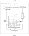
- the voltage monitoring apparatus 10 includes a power conversion module 12 and a microcontroller 14.
- the microcontroller 14 is electrically connected to the power conversion module 12 and may monitor an output voltage of the power conversion module 12. Based on this, when the output voltage of the power conversion module 12 encounters an exception such as overvoltage or undervoltage, the microcontroller 14 may control the power conversion module 12 to stop outputting, to ensure functional safety for the power conversion module 12. It should be understood that based on the voltage monitoring apparatus 10 provided in the implementations, the microcontroller 14 can reach diagnostic coverage of 99% for an SPFM of the output voltage, thereby reaching a corresponding level of ASIL D.
- the microcontroller 14 may further perform a self-check operation during power-on in the voltage monitoring apparatus 10 provided in the implementations of this application, to ensure proper implementation of functions of the microcontroller 14. Based on this, the microcontroller 14 can ensure effective monitoring of the output voltage of the power conversion module 12 during driving, thereby reducing potential driving risks.
- the voltage monitoring apparatus 10 may perform one self-check within one driving cycle. Based on this, it is ensured that functions of the voltage monitoring apparatus 10 can be properly implemented during driving, thereby ensuring functional safety.
- One driving cycle may be a cycle of an electric vehicle from power-on, then driving, to power-off.
- the related self-check operation performed by the voltage monitoring apparatus 10 during power-on may be understood as pre-driving safety mechanism checking of an electric vehicle.
- the power conversion module 12 has an input terminal (not shown in the figure) and an output terminal (not shown in the figure). An input voltage is input from the input terminal and converted by the power conversion module 12. The output terminal may correspondingly output the output voltage obtained through conversion. It should be understood that a source of the input voltage may be a 12 V low-voltage battery input, or a high-voltage battery input, or an input from another power conversion module 12. This is not limited in this application.
- one power conversion module 12 is mainly used as an example for description in the implementations of this application.
- the technical solutions in the implementations of this application may also be applicable to a case in which there are two or more power conversion modules 12.
- the output voltage of the power conversion module 12 is within a specified threshold interval in a normal case. Based on this, the output voltage may be transmitted to other parts of the electric vehicle, so that the other parts implement corresponding functions. For example, the output voltage may enable a motor to implement a function of outputting torque. When the output voltage is outside the threshold interval, it indicates that the output voltage encounters an exception of overvoltage or undervoltage. In this case, the microcontroller 14 may perform a corresponding operation, to ensure that a part of the electric vehicle or the entire electric vehicle can enter a safe state.
- the threshold interval is between the upper voltage threshold and the lower voltage threshold.
- the output voltage is between the upper voltage threshold and the lower voltage threshold.
- the microcontroller 14 further includes a monitoring module 22, an ADC module 24, and an IO module 26.
- the monitoring module 22 is electrically connected to the ADC module 24 and the IO module 26, separately.
- the ADC module 24 may obtain the output voltage of the power conversion module 12 by using a sampling channel. Through cooperation with an external circuit 28, the ADC module 24 may perform fast comparison for the output voltage. Based on a result of the fast comparison, whether the output voltage encounters an exception such as overvoltage or undervoltage can be determined.
- the external circuit 28 may be a bleeder circuit or the like.
- the ADC module 24 includes, for example, a sampling channel Chlx and a sampling channel Chly. It should be understood that the ADC module 24 may further include other sampling channels. This is not limited.
- the external circuit 28 may be a part of the microcontroller 14, whereas in some other implementations, the external circuit 28 may be located outside the microcontroller 14, and be relatively independent of the microcontroller 14.
- overvoltage monitoring is mainly used as an example for description in the implementations of this application, and this is not limited.
- the voltage monitoring apparatus 10 in the implementations may alternatively be applicable to undervoltage monitoring.
- the monitoring module 22 in the microcontroller 14 may include an overvoltage monitoring module, which is configured to monitor overvoltage for the output voltage.
- the monitoring module 22 may include an undervoltage monitoring module, which is configured to monitor undervoltage for the output voltage.
- the ADC module 24 may have a normal mode and a fast compare mode. In normal mode, the ADC module 24 may implement functions such as analog -to-digital conversion. In fast compare mode, the ADC module 24 may perform fast comparison for the output voltage, to determine whether the output voltage encounters an exception such as overvoltage or undervoltage. It should be understood that the ADC module 24 may switch between the normal mode and the fast compare mode based on a use requirement and an application scenario.
- the ADC module 24 may have a comparator function. With the comparator function, the ADC module 24 can directly perform fast comparison for the output voltage without switching between the modes. For example, when the output voltage encounters overvoltage, the ADC module 24 may identify the overvoltage by using the comparator function and trigger an interrupt, so that the monitoring module 22 executes a related program.
- the power conversion module 12 further has a controlled terminal, and the controlled terminal may be electrically connected to the IO module 26. Based on this, when the output voltage of the power conversion module 12 encounters an exception, the microcontroller 14 may send a control signal to a corresponding power conversion module 12 through the IO module 26. The control signal may be used to control the power conversion module 12 to stop outputting.
- the controlled terminal of the power conversion module 12 may further receive an enable signal.
- the power conversion module 12 can output the output voltage based on the enable signal.
- the enable signal is not received or the enable signal is disabled by the control signal, the power conversion module 12 does not output the output voltage.
- the ADC module 24 triggers an interrupt.
- the monitoring module 22 may identify a source of the overvoltage, and send the control signal through the IO module 26. Further, the control signal may disable an enable signal of the corresponding power conversion module 12 and make the power conversion module 12 correspondingly stop outputting, to ensure that the electric vehicle enters a controllable safe state, and guarantee personal safety for driving participants.
- an interrupt processing may alternatively not be performed
- the voltage monitoring apparatus 10 in the implementations monitors the output voltage by using the microcontroller 14, existing peripheral circuits in use such as an external overvoltage monitoring circuit and a self-checking circuit can be cancelled when functional safety is enabled to reach the level of ASIL D. Because these peripheral circuits are cancelled, the voltage monitoring apparatus 10 in the implementations can have higher integration and a circuit board whose area becomes smaller, and BOM costs of the voltage monitoring apparatus 10 can also be reduced.
- the voltage monitoring apparatus 10 provided in the implementations of this application further implements a self-check function, to reach diagnostic coverage of 90% for the LFM.
- the ADC module 24 may diagnose, during power-on, a range of the output voltage transmitted to a corresponding sampling channel, to identify, through diagnosis, a failure of the external circuit 28 and a failure of the ADC module 24.
- the power-on process may be, for example, a process in which a driving participant turns a key to start an electric vehicle.
- the power-on process may alternatively be, for example, a process in which a driving participant starts an electric vehicle by using a smart car key.
- the smart car key may be, for example, a mobile phone with a corresponding car key function.
- the ADC module 24 may diagnose the range of the output voltage of the power conversion module 12. Based on a result of the diagnosis, it can be determined whether the external circuit 28, the ADC module 24, and the corresponding sampling channel operate properly. For example, after the range of the output voltage is diagnosed, a corresponding diagnosis result exceeds a normal range of the output voltage when the external circuit 28 or the ADC module 24 fails, and is within the normal range of the output voltage when the external circuit 28 and the ADC module 24 operate properly.
- the microcontroller 14 further includes a self-checking module 30, a PWM (Pulse Width Modulation) module 32, and a low-pass filter circuit 34.
- the self-checking module 30 is electrically connected to the PWM module 32, to control output of the PWM module 32.
- the PWM module 32 may also be electrically connected to the low-pass filter circuit 34 and the ADC module 24 sequentially. It should be understood that based on control of a duty cycle of the PWM module 32 by the self-checking module 30, the PWM module 32 sends an expected voltage. The expected voltage is transmitted to a corresponding sampling channel of the ADC module 24 after being filtered by the low-pass filter circuit 34, to diagnose whether the sampling channel can operate properly.
- the expected voltage may be greater than the upper voltage threshold. Based on the expected voltage, a fast comparison function of the corresponding sampling channel of the ADC module 24 for overvoltage can be detected. In some other implementations, the expected voltage may be less than the lower voltage threshold. Based on the expected voltage, a fast comparison function of the corresponding sampling channel of the ADC module 24 for undervoltage can be detected.
- an example in which the expected voltage is greater than the upper voltage threshold and the monitoring module 22 is an overvoltage monitoring module is used to describe that the sampling channel Chly of the ADC module 24 may respond to the expected voltage from the PWM module 32 when the ADC module 24 operates properly.
- the overvoltage monitoring module may output the control signal through the IO module 26, to control a corresponding power conversion module 12 to stop outputting.
- the self-checking module 22 may correspondingly detect that an output voltage of the power conversion module 12 encounters undervoltage. Based on this self-check process, it can be determined that structures of the monitoring apparatus operate properly, thereby guaranteeing functional safety for the electric vehicle and reducing potential driving risks.
- an example in which the expected voltage is less than the lower voltage threshold and the monitoring module 22 is an undervoltage monitoring module is used to describe that the sampling channel Chly of the ADC module 24 may respond to the expected voltage from the PWM module 32 when the ADC module 24 operates properly.
- the undervoltage monitoring module may output the control signal through the IO module 26, to control a corresponding power conversion module 12 to stop outputting. Because the power conversion module 12 stops outputting, the monitoring module 22 correspondingly detects that an output voltage of the power conversion module 12 encounters undervoltage.
- software used by the voltage monitoring apparatus 10 is developed according to related process requirements in ISO 26262.
- the software is deployed in the microcontroller 14 with a lockstep core, to enable a corresponding chip safety mechanism. Therefore, in the power-on process, diagnostic coverage of the microcontroller 14 can reach 90% or higher for the LFM, thereby reaching the corresponding level of ASIL D.
- the voltage monitoring apparatus 10 may be an on-board charger or a motor control unit. This is not limited.
- the electric-driven system may further include structures such as a motor.
- the microcontroller 14 may be disposed in the voltage monitoring apparatus 10 in a form of a chip. It should be understood that in the voltage monitoring apparatuses in the implementations of this application, a form in which the microcontroller 14 is presented is not limited.
- An implementation of this application further provides a voltage monitoring method. Similar to the voltage monitoring apparatuses 10 in the foregoing implementations, the voltage monitoring method may be applied to an electric vehicle, to monitor an output voltage of a power conversion module 12.
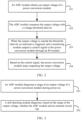
- the voltage monitoring method includes but is not limited to the following steps.
- An ADC module obtains an output voltage of a power conversion module.
- the ADC module may be further electrically connected to an external circuit such as a bleeder circuit.
- the output voltage of the power conversion module is divided by the bleeder circuit and then sent to a corresponding sampling channel of the ADC module.
- the ADC module compares the output voltage with a voltage threshold interval.
- the ADC module may have a normal mode and a fast compare mode.
- normal mode the ADC module may implement functions such as analog-to-digital conversion.
- fast compare mode the ADC module may perform fast comparison for the output voltage, to determine whether the output voltage encounters an exception of overvoltage or undervoltage. It should be understood that the mode of the ADC module may be switched based on a use requirement.
- the ADC module may have a comparator function. With the comparator function, the ADC module can directly perform fast comparison for the output voltage without switching between the modes. For example, when the output voltage encounters overvoltage, the ADC module may identify overvoltage by using the comparator function and trigger an interrupt, so that a monitoring module executes a related program.
- the monitoring module When the output voltage is outside the threshold interval, the monitoring module outputs a control signal to the power conversion module through the IO module.
- the threshold interval is between the upper voltage threshold and the lower voltage threshold. It should be understood that when the power conversion module operates properly, the output voltage of the power conversion module is between the upper voltage threshold and the lower voltage threshold, whereas when the power conversion module encounters an exception, the output voltage of the power conversion module falls outside the threshold interval. For example, when the output voltage is greater than the upper voltage threshold, it indicates that the corresponding output voltage encounters an exception of overvoltage, or when the output voltage is less than the lower voltage threshold, it indicates that the corresponding output voltage encounters an exception of undervoltage. It should be understood that when the output voltage encounters overvoltage, interrupt processing is performed, whereas when the output voltage encounters undervoltage, interrupt processing may not be performed.
- the power conversion module Based on the control signal, the power conversion module stops outputting the output voltage.
- overvoltage monitoring is mainly used as an example for description, and this is not limited.
- the voltage monitoring method in the implementations may also be applied to undervoltage monitoring, and this is not limited.
- the power conversion module may receive an enable signal.
- the power conversion module can output the output voltage based on the enable signal.
- the enable signal is not received, the power conversion module does not output the output voltage.
- the control signal output through the IO module may disable the enable signal, to make the corresponding power conversion module stop outputting.
- the ADC module triggers an interrupt.
- the monitoring module may identify a source of the overvoltage, and send the control signal through the IO module.
- the control signal may disable an enable signal of the corresponding power conversion module and make the power conversion module correspondingly stop outputting, to ensure that an electric vehicle enters a controllable safe state, and guarantee personal safety for driving participants.
- a related safety measure is implemented by using related peripheral resources of a microcontroller.
- functional safety of the corresponding power conversion module can reach a level of ASIL D, and existing peripheral circuits in use such as an external overvoltage monitoring circuit and a self-checking circuit can be cancelled, thereby improving integration and reducing BOM costs of a voltage monitoring apparatus.
- the voltage monitoring method provided in this implementation of this application may further include but is not limited to the following steps.
- the ADC module diagnoses a range of the output voltage of the power conversion module during power-on.
- diagnosis of the range of the output voltage may be implemented by the ADC module in normal mode.
- a self-checking module diagnoses, based on the range of the output voltage, whether the ADC module and the external circuit fail.
- the external circuit, the ADC module, and the corresponding sampling channel of the ADC module fail can be diagnosed during power-on based on the diagnosis of the range of the output voltage. For example, after the range of the output voltage is diagnosed, a corresponding diagnosis result exceeds a normal range of the output voltage when the external circuit or the ADC module fails, and is within the normal range of the output voltage when the external circuit and the ADC module operate properly.
- the voltage monitoring method provided in this implementation of this application may further include but is not limited to the following steps.
- a PWM module sends an expected voltage to the ADC module during power-on.
- the PWM module can be enabled to send an expected voltage with a corresponding duty cycle.
- the ADC module has a normal mode and a fast compare mode.
- the ADC module switches from the normal mode to the fast compare mode through software control, to diagnose the fast comparison function of the ADC module.
- the ADC module may have the comparator function.
- the comparator function of the ADC module can be diagnosed based on the expected voltage.
- the expected voltage may be greater than the upper voltage threshold. Based on the expected voltage, a fast comparison function of the corresponding sampling channel of the ADC module for overvoltage can be detected. In some other implementations, the expected voltage may be less than the lower voltage threshold. Based on the expected voltage, a fast comparison function of the corresponding sampling channel of the ADC module for undervoltage can be detected.
- the monitoring module outputs the control signal to the power conversion module through the IO module.
- an example in which the expected voltage is greater than the upper voltage threshold is used to describe that a sampling channel Chly of the ADC module may respond to the expected voltage from the PWM module when the ADC module operates properly.
- the monitoring module may output the control signal through the IO module.
- the power conversion module Based on the control signal, the power conversion module stops outputting the output voltage.
- control signal may make a corresponding power conversion module stop outputting, and the monitoring module may correspondingly detect that the output voltage of the power conversion module encounters undervoltage. Based on this process, it can be determined that structures of the monitoring apparatus operate properly, thereby guaranteeing functional safety for the electric vehicle and reducing potential driving risks.
- an example in which the expected voltage is less than the lower voltage threshold is used to describe that the sampling channel Chly of the ADC module may respond to the expected voltage from the PWM module when the ADC module operates properly.
- an undervoltage monitoring module may output the control signal through the IO module, to control a corresponding power conversion module to stop outputting. Because the power conversion module stops outputting, the monitoring module correspondingly detects that an output voltage of the power conversion module encounters undervoltage.
Landscapes
- Engineering & Computer Science (AREA)
- Power Engineering (AREA)
- General Physics & Mathematics (AREA)
- Physics & Mathematics (AREA)
- Mechanical Engineering (AREA)
- Transportation (AREA)
- Life Sciences & Earth Sciences (AREA)
- Sustainable Energy (AREA)
- Sustainable Development (AREA)
- Electric Propulsion And Braking For Vehicles (AREA)
- Dc-Dc Converters (AREA)
- Testing Electric Properties And Detecting Electric Faults (AREA)
- Protection Of Static Devices (AREA)
Claims (13)
- Appareil de surveillance de tension (10), susceptible d'être utilisé dans un véhicule électrique, l'appareil de surveillance de tension comprenant un module de conversion de puissance (12) et un microcontrôleur (14) connecté électriquement au module de conversion de puissance ;le module de conversion de puissance étant configuré pour délivrer une tension ;le microcontrôleur comprenant un module de conversion analogique-numérique, ADC, (24), un module de surveillance (22) et un module IO (26),le module ADC étant configuré pour obtenir une tension de sortie du module de conversion de puissance et déterminer si la tension de sortie rencontre ou non une exception ; etle module de surveillance étant configuré pour : lorsque la tension de sortie rencontre une exception, délivrer un signal de commande via le module IO ; etle module de conversion de puissance étant configuré en outre pour cesser de délivrer la tension sur la base du signal de commande ;l'exception comprenant une surtension et une sous-tension ; lorsque la tension de sortie est plus élevée qu'un seuil supérieur de tension, la tension de sortie rencontrant une surtension ; lorsque la tension de sortie est inférieure à un seuil inférieur de tension, la tension de sortie rencontrant une sous-tension ; et le seuil supérieur de tension étant plus grand que le seuil inférieur de tension ;caractérisé en ce quele microcontrôleur comprend en outre un module d'auto-contrôle (30), un module PWM (32) et un circuit filtre passe-bas (34) ; etle module d'auto-contrôle est configuré pour commander un rapport cyclique d'une tension du module PWM durant la mise sous tension, de sorte que le module PWM délivre une tension attendue, la tension attendue étant transmise au module ADC après avoir traversé le circuit filtre passe-bas, afin de diagnostiquer si le module ADC rencontre ou non une exception.
- Appareil de surveillance de tension selon la revendication 1, dans lequel une pluralité de modules de conversion de puissance sont présents, et le module de surveillance est configuré en outre pour : lorsque la tension de sortie rencontre une exception, identifier un module de conversion de puissance qui rencontre une exception, afin de délivrer corrélativement le signal de commande.
- Appareil de surveillance de tension selon la revendication 1 ou 2, dans lequel le microcontrôleur comprend en outre un circuit externe (28), le circuit externe est connecté électriquement entre le module ADC et le module de conversion de puissance, et la tension de sortie est transmise au module ADC après avoir traversé le circuit externe.
- Appareil de surveillance de tension selon la revendication 3, dans lequel le circuit externe est un circuit diviseur de tension.
- Appareil de surveillance de tension selon l'une quelconque des revendications 1 à 4, dans lequel le module ADC déclenche une interruption sur la base de la tension attendue, et le module de surveillance est configuré pour délivrer le signal de commande au module de conversion de puissance via le module IO durant l'interruption, de sorte que le module de conversion de puissance cesse de délivrer une tension, et le module ADC apprend, grâce à la surveillance, que la tension de sortie rencontre une exception.
- Appareil de surveillance de tension selon la revendication 6, dans lequel le module ADC est configuré en outre pour obtenir une plage de la tension de sortie au cours de la mise sous tension, et le module d'auto-contrôle est configuré en outre pour diagnostiquer, sur la base de la plage de la tension de sortie, si le module ADC connaît ou non une défaillance.
- Appareil de surveillance de tension selon la revendication 6, dans lequel le module ADC est pourvu d'une fonction de comparaison pour surveiller si la tension de sortie rencontre ou non une exception et pour obtenir la plage de la tension de sortie au cours de la mise sous tension.
- Véhicule électrique, comprenant l'appareil de surveillance de tension selon l'une quelconque des revendications 1 à 7.
- Procédé de surveillance de tension, appliqué à un véhicule électrique, le procédé de surveillance de tension comprenant :l'obtention (101), par un module ADC, d'une tension de sortie d'un module de conversion de puissance ;lorsque le module ADC détermine que la tension de sortie rencontre une exception, la délivrance (102, 103), par un module de surveillance, d'un signal de commande au module de conversion de puissance via un module IO, l'exception comprenant une surtension ou une sous-tension ; etla commande (103, 104), sur la base du signal de commande, au module de conversion de puissance de cesser de délivrer la tension ;l'exception comprenant une surtension et une sous-tension ; lorsque la tension de sortie est plus élevée qu'un seuil supérieur de tension, la tension de sortie rencontrant une surtension ; lorsque la tension de sortie est inférieure à un seuil inférieur de tension, la tension de sortie rencontrant une sous-tension ; et le seuil supérieur de tension étant plus grand que le seuil inférieur de tension ;le procédé étant caractérisé en ce qu'il comprend en outre :la commande, par un module d'auto-contrôle, d'un rapport cyclique d'une tension d'un module PWM au cours de la mise sous tension, de sorte que le module PWM délivre une tension attendue, etla transmission, par le module d'auto-contrôle, de la tension attendue au module ADC après qu'elle a traversé le circuit filtre passe-bas, afin de diagnostiquer si le module ADC rencontre ou non une exception.
- Procédé de surveillance de tension selon la revendication 9, dans lequel une pluralité de modules de conversion de puissance sont présents, et le procédé comprenant en outre :
l'identification, par le module de surveillance, d'un module de conversion de puissance qui rencontre une exception, afin de délivrer corrélativement le signal de commande. - Procédé de surveillance de tension selon la revendication 9 ou 10, comprenant en outre, avant l'obtention, par un module ADC, d'une tension de sortie d'un module de conversion de puissance : la division, par un circuit diviseur de tension, de la tension de sortie et la transmission de la tension de sortie au module ADC.
- Procédé de surveillance de tension selon la revendication 11, le procédé comprenant en outre :l'obtention, par le module ADC, d'une plage de la tension de sortie au cours de la mise sous tension ; etle diagnostic, par le module d'auto-contrôle sur la base de la plage de la tension de sortie, si le module ADC et le circuit diviseur de tension connaissent ou non une défaillance.
- Procédé de surveillance de tension selon la revendication 11, le procédé comprenant en outre :la commande, par un module d'auto-contrôle, d'un rapport cyclique d'une tension d'un module PWM au cours de la mise sous tension, de sorte que le module PWM envoie une tension attendue au module ADC ;la détermination, par le module ADC sur la base de la tension attendue, que la tension de sortie rencontre une exception ;la délivrance, par le module de surveillance, du signal de commande via la module IO ; etla commande, sur la base du signal de commande, au module de conversion de puissance de cesser de délivrer une tension.
Applications Claiming Priority (1)
| Application Number | Priority Date | Filing Date | Title |
|---|---|---|---|
| CN202110223125.0A CN114290901A (zh) | 2021-02-26 | 2021-02-26 | 电压监控方法、电压监控装置及电动汽车 |
Publications (3)
| Publication Number | Publication Date |
|---|---|
| EP4049882A2 EP4049882A2 (fr) | 2022-08-31 |
| EP4049882A3 EP4049882A3 (fr) | 2022-11-23 |
| EP4049882B1 true EP4049882B1 (fr) | 2023-11-01 |
Family
ID=80624037
Family Applications (1)
| Application Number | Title | Priority Date | Filing Date |
|---|---|---|---|
| EP22159017.7A Active EP4049882B1 (fr) | 2021-02-26 | 2022-02-25 | Procédé de surveillance de tension, procédé de surveillance de tension, et véhicule électrique |
Country Status (4)
| Country | Link |
|---|---|
| US (1) | US20220203864A1 (fr) |
| EP (1) | EP4049882B1 (fr) |
| JP (1) | JP2022132179A (fr) |
| CN (1) | CN114290901A (fr) |
Families Citing this family (6)
| Publication number | Priority date | Publication date | Assignee | Title |
|---|---|---|---|---|
| US12265104B2 (en) * | 2022-06-17 | 2025-04-01 | Changxin Memory Technologies, Inc. | Voltage detection circuit and voltage detection method |
| EP4361651B1 (fr) * | 2022-10-28 | 2025-02-19 | Preh GmbH | Dispositif de commande doté d'une surveillance fonctionnelle de la détection de l'état de commutation d'au moins un élément de commutation actionnable associé, utilisation et procédé associés |
| CN115639399A (zh) * | 2022-11-21 | 2023-01-24 | 江铃汽车股份有限公司 | 一种电压异常检测系统及保护方法 |
| US11801754B1 (en) * | 2022-12-15 | 2023-10-31 | Mercedes-Benz Group AG | System, device, and/or process for determining motor driver safety state for electric vehicle |
| EP4632399A1 (fr) * | 2024-04-12 | 2025-10-15 | Preh GmbH | Dispositif de commande doté d'une surveillance fonctionnelle de la détection d'état de commutation, utilisation et procédé associés |
| WO2026065721A1 (fr) * | 2024-09-25 | 2026-04-02 | 惠州亿纬锂能股份有限公司 | Circuit de détection de tension et procédé de détection de tension |
Family Cites Families (12)
| Publication number | Priority date | Publication date | Assignee | Title |
|---|---|---|---|---|
| US3800198A (en) * | 1971-08-16 | 1974-03-26 | Gen Electric | Protection means for preventing overvoltage and undervoltage conditions in power circuits |
| US7277304B2 (en) * | 2005-09-23 | 2007-10-02 | Gm Global Technology Operations, Inc. | Multiple inverter system with single controller and related operating method |
| JP5681210B2 (ja) * | 2010-12-07 | 2015-03-04 | 日立オートモティブシステムズ株式会社 | 電力変換装置 |
| US8432118B2 (en) * | 2011-05-02 | 2013-04-30 | Deere & Company | Inverter and a method for controlling an electric machine |
| US9407098B2 (en) * | 2011-12-12 | 2016-08-02 | Apple Inc. | Determining a battery chemistry for a battery in a peripheral device |
| US9234943B2 (en) * | 2011-12-16 | 2016-01-12 | Lear Corporation | Method and system for battery current measurement calibration |
| JP6400610B2 (ja) * | 2014-02-06 | 2018-10-03 | 日立オートモティブシステムズ株式会社 | 負荷駆動回路 |
| CN205113224U (zh) * | 2015-11-05 | 2016-03-30 | 中国船舶重工集团公司第七一六研究所 | 一种车载模块输入电源监控装置 |
| CN105911353B (zh) * | 2016-04-15 | 2018-09-14 | 广州汽车集团股份有限公司 | 汽车绝缘电阻检测电路及其绝缘电阻检测方法 |
| JP6766506B2 (ja) * | 2016-08-02 | 2020-10-14 | 株式会社オートネットワーク技術研究所 | 異常検出装置及び車載用電源装置 |
| JP7070388B2 (ja) * | 2018-12-17 | 2022-05-18 | トヨタ自動車株式会社 | 充電システム |
| CN112234690A (zh) * | 2020-12-15 | 2021-01-15 | 鹏城实验室 | 电源保护电路、设备以及方法 |
-
2021
- 2021-02-26 CN CN202110223125.0A patent/CN114290901A/zh active Pending
-
2022
- 2022-02-25 US US17/680,775 patent/US20220203864A1/en not_active Abandoned
- 2022-02-25 JP JP2022027758A patent/JP2022132179A/ja active Pending
- 2022-02-25 EP EP22159017.7A patent/EP4049882B1/fr active Active
Also Published As
| Publication number | Publication date |
|---|---|
| EP4049882A2 (fr) | 2022-08-31 |
| JP2022132179A (ja) | 2022-09-07 |
| US20220203864A1 (en) | 2022-06-30 |
| EP4049882A3 (fr) | 2022-11-23 |
| CN114290901A (zh) | 2022-04-08 |
Similar Documents
| Publication | Publication Date | Title |
|---|---|---|
| EP4049882B1 (fr) | Procédé de surveillance de tension, procédé de surveillance de tension, et véhicule électrique | |
| US20250080031A1 (en) | Motor control system and vehicle with same | |
| US9651625B2 (en) | Battery monitoring apparatus and battery monitoring system | |
| JP5853099B2 (ja) | 電池制御装置 | |
| EP3958466B1 (fr) | Circuit de déclenchement et dispositif de fusible électronique le comprenant | |
| US10532724B2 (en) | Method for operating a parking brake and control unit for operating a parking brake | |
| US11888388B2 (en) | Electric compressor control device | |
| JP2003512711A (ja) | 燃料電池の電気出力と絶縁電気回路網との切換え接続を制御するための方法および装置 | |
| JP6983991B2 (ja) | 電池制御装置 | |
| JP2010279146A (ja) | 複数組電池の電圧監視装置 | |
| US11979095B2 (en) | Discharge control circuit and power conversion device | |
| JP2013521437A (ja) | 電流回路を作動するためのエンジン制御装置およびエンジン制御方法 | |
| EP2783904A2 (fr) | Système de véhicule | |
| US12176502B2 (en) | Battery apparatus and diagnosing method of heater | |
| CN112350276A (zh) | 电机的驱动控制系统及其控制方法、电机控制器以及车辆 | |
| CN112703650B (zh) | 具有冗余电源的机动车辆控制单元和相应的机动车辆 | |
| EP3627686B1 (fr) | Dispositif de pilotage de moteur | |
| CN115133620A (zh) | 供电电路及其控制方法、装置及介质 | |
| KR101204512B1 (ko) | 전기구동 이동체의 릴레이 오류 및 릴레이 제어오류 검출 시스템 및 방법 | |
| JP7487750B2 (ja) | 車載システム及び車両 | |
| US12221086B2 (en) | Power supply system | |
| KR102799269B1 (ko) | 차량의 인버터용 고장 진단 장치 및 방법 | |
| US12162364B2 (en) | Vehicle comprising a standby power supply device and method for operating same | |
| JP2025183840A (ja) | 電源監視装置 | |
| EP4485742A1 (fr) | Système de gestion de batterie, bloc-batterie et procédé de commande de dispositif de commutation |
Legal Events
| Date | Code | Title | Description |
|---|---|---|---|
| PUAI | Public reference made under article 153(3) epc to a published international application that has entered the european phase |
Free format text: ORIGINAL CODE: 0009012 |
|
| STAA | Information on the status of an ep patent application or granted ep patent |
Free format text: STATUS: THE APPLICATION HAS BEEN PUBLISHED |
|
| AK | Designated contracting states |
Kind code of ref document: A2 Designated state(s): AL AT BE BG CH CY CZ DE DK EE ES FI FR GB GR HR HU IE IS IT LI LT LU LV MC MK MT NL NO PL PT RO RS SE SI SK SM TR |
|
| PUAL | Search report despatched |
Free format text: ORIGINAL CODE: 0009013 |
|
| AK | Designated contracting states |
Kind code of ref document: A3 Designated state(s): AL AT BE BG CH CY CZ DE DK EE ES FI FR GB GR HR HU IE IS IT LI LT LU LV MC MK MT NL NO PL PT RO RS SE SI SK SM TR |
|
| RIC1 | Information provided on ipc code assigned before grant |
Ipc: B60L 3/04 20060101ALI20221020BHEP Ipc: B60L 3/00 20190101AFI20221020BHEP |
|
| STAA | Information on the status of an ep patent application or granted ep patent |
Free format text: STATUS: REQUEST FOR EXAMINATION WAS MADE |
|
| 17P | Request for examination filed |
Effective date: 20230324 |
|
| RBV | Designated contracting states (corrected) |
Designated state(s): AL AT BE BG CH CY CZ DE DK EE ES FI FR GB GR HR HU IE IS IT LI LT LU LV MC MK MT NL NO PL PT RO RS SE SI SK SM TR |
|
| GRAP | Despatch of communication of intention to grant a patent |
Free format text: ORIGINAL CODE: EPIDOSNIGR1 |
|
| STAA | Information on the status of an ep patent application or granted ep patent |
Free format text: STATUS: GRANT OF PATENT IS INTENDED |
|
| INTG | Intention to grant announced |
Effective date: 20230607 |
|
| RIN1 | Information on inventor provided before grant (corrected) |
Inventor name: ZHANG, XING Inventor name: ZHAO, YUNWU Inventor name: KONG, XUEJUAN |
|
| P01 | Opt-out of the competence of the unified patent court (upc) registered |
Effective date: 20230727 |
|
| GRAS | Grant fee paid |
Free format text: ORIGINAL CODE: EPIDOSNIGR3 |
|
| GRAA | (expected) grant |
Free format text: ORIGINAL CODE: 0009210 |
|
| STAA | Information on the status of an ep patent application or granted ep patent |
Free format text: STATUS: THE PATENT HAS BEEN GRANTED |
|
| AK | Designated contracting states |
Kind code of ref document: B1 Designated state(s): AL AT BE BG CH CY CZ DE DK EE ES FI FR GB GR HR HU IE IS IT LI LT LU LV MC MK MT NL NO PL PT RO RS SE SI SK SM TR |
|
| REG | Reference to a national code |
Ref country code: GB Ref legal event code: FG4D |
|
| REG | Reference to a national code |
Ref country code: CH Ref legal event code: EP |
|
| REG | Reference to a national code |
Ref country code: IE Ref legal event code: FG4D |
|
| REG | Reference to a national code |
Ref country code: DE Ref legal event code: R096 Ref document number: 602022000809 Country of ref document: DE |
|
| REG | Reference to a national code |
Ref country code: LT Ref legal event code: MG9D |
|
| REG | Reference to a national code |
Ref country code: NL Ref legal event code: MP Effective date: 20231101 |
|
| PG25 | Lapsed in a contracting state [announced via postgrant information from national office to epo] |
Ref country code: GR Free format text: LAPSE BECAUSE OF FAILURE TO SUBMIT A TRANSLATION OF THE DESCRIPTION OR TO PAY THE FEE WITHIN THE PRESCRIBED TIME-LIMIT Effective date: 20240202 |
|
| PG25 | Lapsed in a contracting state [announced via postgrant information from national office to epo] |
Ref country code: IS Free format text: LAPSE BECAUSE OF FAILURE TO SUBMIT A TRANSLATION OF THE DESCRIPTION OR TO PAY THE FEE WITHIN THE PRESCRIBED TIME-LIMIT Effective date: 20240301 |
|
| PG25 | Lapsed in a contracting state [announced via postgrant information from national office to epo] |
Ref country code: LT Free format text: LAPSE BECAUSE OF FAILURE TO SUBMIT A TRANSLATION OF THE DESCRIPTION OR TO PAY THE FEE WITHIN THE PRESCRIBED TIME-LIMIT Effective date: 20231101 |
|
| REG | Reference to a national code |
Ref country code: AT Ref legal event code: MK05 Ref document number: 1626845 Country of ref document: AT Kind code of ref document: T Effective date: 20231101 |
|
| PG25 | Lapsed in a contracting state [announced via postgrant information from national office to epo] |
Ref country code: NL Free format text: LAPSE BECAUSE OF FAILURE TO SUBMIT A TRANSLATION OF THE DESCRIPTION OR TO PAY THE FEE WITHIN THE PRESCRIBED TIME-LIMIT Effective date: 20231101 |
|
| PG25 | Lapsed in a contracting state [announced via postgrant information from national office to epo] |
Ref country code: AT Free format text: LAPSE BECAUSE OF FAILURE TO SUBMIT A TRANSLATION OF THE DESCRIPTION OR TO PAY THE FEE WITHIN THE PRESCRIBED TIME-LIMIT Effective date: 20231101 |
|
| PG25 | Lapsed in a contracting state [announced via postgrant information from national office to epo] |
Ref country code: ES Free format text: LAPSE BECAUSE OF FAILURE TO SUBMIT A TRANSLATION OF THE DESCRIPTION OR TO PAY THE FEE WITHIN THE PRESCRIBED TIME-LIMIT Effective date: 20231101 |
|
| PG25 | Lapsed in a contracting state [announced via postgrant information from national office to epo] |
Ref country code: NL Free format text: LAPSE BECAUSE OF FAILURE TO SUBMIT A TRANSLATION OF THE DESCRIPTION OR TO PAY THE FEE WITHIN THE PRESCRIBED TIME-LIMIT Effective date: 20231101 Ref country code: LT Free format text: LAPSE BECAUSE OF FAILURE TO SUBMIT A TRANSLATION OF THE DESCRIPTION OR TO PAY THE FEE WITHIN THE PRESCRIBED TIME-LIMIT Effective date: 20231101 Ref country code: IS Free format text: LAPSE BECAUSE OF FAILURE TO SUBMIT A TRANSLATION OF THE DESCRIPTION OR TO PAY THE FEE WITHIN THE PRESCRIBED TIME-LIMIT Effective date: 20240301 Ref country code: GR Free format text: LAPSE BECAUSE OF FAILURE TO SUBMIT A TRANSLATION OF THE DESCRIPTION OR TO PAY THE FEE WITHIN THE PRESCRIBED TIME-LIMIT Effective date: 20240202 Ref country code: ES Free format text: LAPSE BECAUSE OF FAILURE TO SUBMIT A TRANSLATION OF THE DESCRIPTION OR TO PAY THE FEE WITHIN THE PRESCRIBED TIME-LIMIT Effective date: 20231101 Ref country code: BG Free format text: LAPSE BECAUSE OF FAILURE TO SUBMIT A TRANSLATION OF THE DESCRIPTION OR TO PAY THE FEE WITHIN THE PRESCRIBED TIME-LIMIT Effective date: 20240201 Ref country code: AT Free format text: LAPSE BECAUSE OF FAILURE TO SUBMIT A TRANSLATION OF THE DESCRIPTION OR TO PAY THE FEE WITHIN THE PRESCRIBED TIME-LIMIT Effective date: 20231101 Ref country code: PT Free format text: LAPSE BECAUSE OF FAILURE TO SUBMIT A TRANSLATION OF THE DESCRIPTION OR TO PAY THE FEE WITHIN THE PRESCRIBED TIME-LIMIT Effective date: 20240301 |
|
| PG25 | Lapsed in a contracting state [announced via postgrant information from national office to epo] |
Ref country code: SE Free format text: LAPSE BECAUSE OF FAILURE TO SUBMIT A TRANSLATION OF THE DESCRIPTION OR TO PAY THE FEE WITHIN THE PRESCRIBED TIME-LIMIT Effective date: 20231101 Ref country code: RS Free format text: LAPSE BECAUSE OF FAILURE TO SUBMIT A TRANSLATION OF THE DESCRIPTION OR TO PAY THE FEE WITHIN THE PRESCRIBED TIME-LIMIT Effective date: 20231101 Ref country code: PL Free format text: LAPSE BECAUSE OF FAILURE TO SUBMIT A TRANSLATION OF THE DESCRIPTION OR TO PAY THE FEE WITHIN THE PRESCRIBED TIME-LIMIT Effective date: 20231101 Ref country code: NO Free format text: LAPSE BECAUSE OF FAILURE TO SUBMIT A TRANSLATION OF THE DESCRIPTION OR TO PAY THE FEE WITHIN THE PRESCRIBED TIME-LIMIT Effective date: 20240201 Ref country code: LV Free format text: LAPSE BECAUSE OF FAILURE TO SUBMIT A TRANSLATION OF THE DESCRIPTION OR TO PAY THE FEE WITHIN THE PRESCRIBED TIME-LIMIT Effective date: 20231101 Ref country code: HR Free format text: LAPSE BECAUSE OF FAILURE TO SUBMIT A TRANSLATION OF THE DESCRIPTION OR TO PAY THE FEE WITHIN THE PRESCRIBED TIME-LIMIT Effective date: 20231101 |
|
| PG25 | Lapsed in a contracting state [announced via postgrant information from national office to epo] |
Ref country code: DK Free format text: LAPSE BECAUSE OF FAILURE TO SUBMIT A TRANSLATION OF THE DESCRIPTION OR TO PAY THE FEE WITHIN THE PRESCRIBED TIME-LIMIT Effective date: 20231101 |
|
| PG25 | Lapsed in a contracting state [announced via postgrant information from national office to epo] |
Ref country code: CZ Free format text: LAPSE BECAUSE OF FAILURE TO SUBMIT A TRANSLATION OF THE DESCRIPTION OR TO PAY THE FEE WITHIN THE PRESCRIBED TIME-LIMIT Effective date: 20231101 |
|
| PG25 | Lapsed in a contracting state [announced via postgrant information from national office to epo] |
Ref country code: SK Free format text: LAPSE BECAUSE OF FAILURE TO SUBMIT A TRANSLATION OF THE DESCRIPTION OR TO PAY THE FEE WITHIN THE PRESCRIBED TIME-LIMIT Effective date: 20231101 |
|
| PG25 | Lapsed in a contracting state [announced via postgrant information from national office to epo] |
Ref country code: SM Free format text: LAPSE BECAUSE OF FAILURE TO SUBMIT A TRANSLATION OF THE DESCRIPTION OR TO PAY THE FEE WITHIN THE PRESCRIBED TIME-LIMIT Effective date: 20231101 Ref country code: SK Free format text: LAPSE BECAUSE OF FAILURE TO SUBMIT A TRANSLATION OF THE DESCRIPTION OR TO PAY THE FEE WITHIN THE PRESCRIBED TIME-LIMIT Effective date: 20231101 Ref country code: IT Free format text: LAPSE BECAUSE OF FAILURE TO SUBMIT A TRANSLATION OF THE DESCRIPTION OR TO PAY THE FEE WITHIN THE PRESCRIBED TIME-LIMIT Effective date: 20231101 Ref country code: EE Free format text: LAPSE BECAUSE OF FAILURE TO SUBMIT A TRANSLATION OF THE DESCRIPTION OR TO PAY THE FEE WITHIN THE PRESCRIBED TIME-LIMIT Effective date: 20231101 Ref country code: DK Free format text: LAPSE BECAUSE OF FAILURE TO SUBMIT A TRANSLATION OF THE DESCRIPTION OR TO PAY THE FEE WITHIN THE PRESCRIBED TIME-LIMIT Effective date: 20231101 Ref country code: CZ Free format text: LAPSE BECAUSE OF FAILURE TO SUBMIT A TRANSLATION OF THE DESCRIPTION OR TO PAY THE FEE WITHIN THE PRESCRIBED TIME-LIMIT Effective date: 20231101 |
|
| REG | Reference to a national code |
Ref country code: DE Ref legal event code: R097 Ref document number: 602022000809 Country of ref document: DE |
|
| PLBE | No opposition filed within time limit |
Free format text: ORIGINAL CODE: 0009261 |
|
| STAA | Information on the status of an ep patent application or granted ep patent |
Free format text: STATUS: NO OPPOSITION FILED WITHIN TIME LIMIT |
|
| PG25 | Lapsed in a contracting state [announced via postgrant information from national office to epo] |
Ref country code: MC Free format text: LAPSE BECAUSE OF FAILURE TO SUBMIT A TRANSLATION OF THE DESCRIPTION OR TO PAY THE FEE WITHIN THE PRESCRIBED TIME-LIMIT Effective date: 20231101 |
|
| 26N | No opposition filed |
Effective date: 20240802 |
|
| PG25 | Lapsed in a contracting state [announced via postgrant information from national office to epo] |
Ref country code: LU Free format text: LAPSE BECAUSE OF NON-PAYMENT OF DUE FEES Effective date: 20240225 |
|
| PG25 | Lapsed in a contracting state [announced via postgrant information from national office to epo] |
Ref country code: SI Free format text: LAPSE BECAUSE OF FAILURE TO SUBMIT A TRANSLATION OF THE DESCRIPTION OR TO PAY THE FEE WITHIN THE PRESCRIBED TIME-LIMIT Effective date: 20231101 |
|
| PG25 | Lapsed in a contracting state [announced via postgrant information from national office to epo] |
Ref country code: SI Free format text: LAPSE BECAUSE OF FAILURE TO SUBMIT A TRANSLATION OF THE DESCRIPTION OR TO PAY THE FEE WITHIN THE PRESCRIBED TIME-LIMIT Effective date: 20231101 Ref country code: LU Free format text: LAPSE BECAUSE OF NON-PAYMENT OF DUE FEES Effective date: 20240225 |
|
| REG | Reference to a national code |
Ref country code: BE Ref legal event code: MM Effective date: 20240229 |
|
| PG25 | Lapsed in a contracting state [announced via postgrant information from national office to epo] |
Ref country code: BE Free format text: LAPSE BECAUSE OF NON-PAYMENT OF DUE FEES Effective date: 20240229 |
|
| PG25 | Lapsed in a contracting state [announced via postgrant information from national office to epo] |
Ref country code: IE Free format text: LAPSE BECAUSE OF NON-PAYMENT OF DUE FEES Effective date: 20240225 |
|
| PG25 | Lapsed in a contracting state [announced via postgrant information from national office to epo] |
Ref country code: IE Free format text: LAPSE BECAUSE OF NON-PAYMENT OF DUE FEES Effective date: 20240225 Ref country code: BE Free format text: LAPSE BECAUSE OF NON-PAYMENT OF DUE FEES Effective date: 20240229 |
|
| PG25 | Lapsed in a contracting state [announced via postgrant information from national office to epo] |
Ref country code: RO Free format text: LAPSE BECAUSE OF FAILURE TO SUBMIT A TRANSLATION OF THE DESCRIPTION OR TO PAY THE FEE WITHIN THE PRESCRIBED TIME-LIMIT Effective date: 20231101 |
|
| PG25 | Lapsed in a contracting state [announced via postgrant information from national office to epo] |
Ref country code: CY Free format text: LAPSE BECAUSE OF FAILURE TO SUBMIT A TRANSLATION OF THE DESCRIPTION OR TO PAY THE FEE WITHIN THE PRESCRIBED TIME-LIMIT; INVALID AB INITIO Effective date: 20220225 |
|
| REG | Reference to a national code |
Ref country code: CH Ref legal event code: PL |
|
| PG25 | Lapsed in a contracting state [announced via postgrant information from national office to epo] |
Ref country code: FI Free format text: LAPSE BECAUSE OF FAILURE TO SUBMIT A TRANSLATION OF THE DESCRIPTION OR TO PAY THE FEE WITHIN THE PRESCRIBED TIME-LIMIT Effective date: 20231101 |
|
| PG25 | Lapsed in a contracting state [announced via postgrant information from national office to epo] |
Ref country code: CH Free format text: LAPSE BECAUSE OF NON-PAYMENT OF DUE FEES Effective date: 20250228 |
|
| PG25 | Lapsed in a contracting state [announced via postgrant information from national office to epo] |
Ref country code: TR Free format text: LAPSE BECAUSE OF FAILURE TO SUBMIT A TRANSLATION OF THE DESCRIPTION OR TO PAY THE FEE WITHIN THE PRESCRIBED TIME-LIMIT Effective date: 20231101 |
|
| PGFP | Annual fee paid to national office [announced via postgrant information from national office to epo] |
Ref country code: FR Payment date: 20251231 Year of fee payment: 5 |
|
| PGFP | Annual fee paid to national office [announced via postgrant information from national office to epo] |
Ref country code: GB Payment date: 20260106 Year of fee payment: 5 |
|
| PGFP | Annual fee paid to national office [announced via postgrant information from national office to epo] |
Ref country code: DE Payment date: 20260102 Year of fee payment: 5 |