EP4049936B1 - System mit einem beweglichen schlitten und verfahren zur anwendung eines solchen systems mit beweglichem schlitten - Google Patents
System mit einem beweglichen schlitten und verfahren zur anwendung eines solchen systems mit beweglichem schlitten Download PDFInfo
- Publication number
- EP4049936B1 EP4049936B1 EP22159033.4A EP22159033A EP4049936B1 EP 4049936 B1 EP4049936 B1 EP 4049936B1 EP 22159033 A EP22159033 A EP 22159033A EP 4049936 B1 EP4049936 B1 EP 4049936B1
- Authority
- EP
- European Patent Office
- Prior art keywords
- movable module
- module
- mobile
- mobile module
- fork
- Prior art date
- Legal status (The legal status is an assumption and is not a legal conclusion. Google has not performed a legal analysis and makes no representation as to the accuracy of the status listed.)
- Active
Links
Images



Classifications
-
- B—PERFORMING OPERATIONS; TRANSPORTING
- B64—AIRCRAFT; AVIATION; COSMONAUTICS
- B64F—GROUND OR AIRCRAFT-CARRIER-DECK INSTALLATIONS SPECIALLY ADAPTED FOR USE IN CONNECTION WITH AIRCRAFT; DESIGNING, MANUFACTURING, ASSEMBLING, CLEANING, MAINTAINING OR REPAIRING AIRCRAFT, NOT OTHERWISE PROVIDED FOR; HANDLING, TRANSPORTING, TESTING OR INSPECTING AIRCRAFT COMPONENTS, NOT OTHERWISE PROVIDED FOR
- B64F5/00—Designing, manufacturing, assembling, cleaning, maintaining or repairing aircraft, not otherwise provided for; Handling, transporting, testing or inspecting aircraft components, not otherwise provided for
- B64F5/50—Handling or transporting aircraft components
-
- B—PERFORMING OPERATIONS; TRANSPORTING
- B64—AIRCRAFT; AVIATION; COSMONAUTICS
- B64F—GROUND OR AIRCRAFT-CARRIER-DECK INSTALLATIONS SPECIALLY ADAPTED FOR USE IN CONNECTION WITH AIRCRAFT; DESIGNING, MANUFACTURING, ASSEMBLING, CLEANING, MAINTAINING OR REPAIRING AIRCRAFT, NOT OTHERWISE PROVIDED FOR; HANDLING, TRANSPORTING, TESTING OR INSPECTING AIRCRAFT COMPONENTS, NOT OTHERWISE PROVIDED FOR
- B64F5/00—Designing, manufacturing, assembling, cleaning, maintaining or repairing aircraft, not otherwise provided for; Handling, transporting, testing or inspecting aircraft components, not otherwise provided for
- B64F5/10—Manufacturing or assembling aircraft, e.g. jigs therefor
-
- F—MECHANICAL ENGINEERING; LIGHTING; HEATING; WEAPONS; BLASTING
- F01—MACHINES OR ENGINES IN GENERAL; ENGINE PLANTS IN GENERAL; STEAM ENGINES
- F01D—NON-POSITIVE DISPLACEMENT MACHINES OR ENGINES, e.g. STEAM TURBINES
- F01D5/00—Blades; Blade-carrying members; Heating, heat-insulating, cooling or antivibration means on the blades or the members
- F01D5/005—Repairing methods or devices
-
- F—MECHANICAL ENGINEERING; LIGHTING; HEATING; WEAPONS; BLASTING
- F01—MACHINES OR ENGINES IN GENERAL; ENGINE PLANTS IN GENERAL; STEAM ENGINES
- F01D—NON-POSITIVE DISPLACEMENT MACHINES OR ENGINES, e.g. STEAM TURBINES
- F01D25/00—Component parts, details, or accessories, not provided for in, or of interest apart from, other groups
- F01D25/28—Supporting or mounting arrangements, e.g. for turbine casing
- F01D25/285—Temporary support structures, e.g. for testing, assembling, installing, repairing; Assembly methods using such structures
-
- F—MECHANICAL ENGINEERING; LIGHTING; HEATING; WEAPONS; BLASTING
- F05—INDEXING SCHEMES RELATING TO ENGINES OR PUMPS IN VARIOUS SUBCLASSES OF CLASSES F01-F04
- F05D—INDEXING SCHEME FOR ASPECTS RELATING TO NON-POSITIVE-DISPLACEMENT MACHINES OR ENGINES, GAS-TURBINES OR JET-PROPULSION PLANTS
- F05D2230/00—Manufacture
- F05D2230/72—Maintenance
-
- F—MECHANICAL ENGINEERING; LIGHTING; HEATING; WEAPONS; BLASTING
- F05—INDEXING SCHEMES RELATING TO ENGINES OR PUMPS IN VARIOUS SUBCLASSES OF CLASSES F01-F04
- F05D—INDEXING SCHEME FOR ASPECTS RELATING TO NON-POSITIVE-DISPLACEMENT MACHINES OR ENGINES, GAS-TURBINES OR JET-PROPULSION PLANTS
- F05D2230/00—Manufacture
- F05D2230/80—Repairing, retrofitting or upgrading methods
Definitions
- the invention relates to a movable carriage system for an aircraft element such as an aircraft engine.
- the invention also relates to a method of implementing a mobile carriage system for such an aircraft element.
- Aircraft engines are equipment that are very frequently assembled and dismantled, particularly for maintenance operations. These operations require suitable handling systems.
- transport frames for aircraft engines capable of being used in all phases of the engine's life, in particular assembly, transport, lifting, maintenance, storage or even installation and installation. drop off on plane.
- transport frames are known comprising a cradle capable of receiving a motor and a rolling base receiving said cradle, in particular for the rolling and road or air transport phases.
- the document DE10 2015 214667 A1 relates to a system for assembling and disassembling an aircraft engine and includes two movable modules.
- the invention aims to overcome all of these drawbacks.
- the invention aims to propose a mobile trolley system adapted to be able to move an aircraft element of large size (several meters in length and several meters in width and/or diameter) and of significant mass, which can in particular go up to 20 tonnes (20,000 kg) or more.
- the invention also aims to propose such a mobile trolley system itself having a reduced footprint.
- the invention also aims to provide such a mobile trolley system providing perfect safety of use.
- the invention also aims to propose a method of implementing such a safe mobile trolley system which is easy to produce and saves significant time.
- the mobile trolley system is characterized in that the first mobile module and the second mobile module are adapted to be able to be controlled and moved independently of each other and simultaneously in a coordinated manner with each other when they are secured to each other at using at least one connecting arm, and the lifting device of each mobile module being adapted to be able to move the aircraft element vertically and by an inclination relative to a lifting plane orthogonal to said vertical direction.
- each lifting device makes it possible to load, transport, lift and also precisely position an aircraft element in height.
- the forks can load the aircraft component through a transport frame.
- a mobile trolley system according to the invention thus allows the handling, in particular the movement on the ground and the lifting, of such an aircraft element without requiring any particular adaptation or accessories generally used to adapt to each situation and in particular to all transport frames and aircraft engines of various dimensions, while having a reduced footprint, each mobile module can also be controlled and moved independently of each other or in a coordinated manner when they are secured together using at least one connecting arm allowing a reliable mechanical and physical communication connection between said first mobile module and said second mobile module.
- the mobile cart system comprises at least one connecting arm comprising a communication cable adapted to allow data transmission between the first mobile module and the second mobile module.
- each mobile module is also generally the axis along which each mobile module according to the invention has the largest overall dimension.
- the width of a mobile module according to the invention is a dimension of the latter along a horizontal axis, called transverse axis, orthogonal to said longitudinal axis.
- a forward orientation and a rearward orientation can be defined along said longitudinal axis, the system according to the invention having a main direction, called forward direction, of advancement along said longitudinal axis, the system according to the invention being however adapted to be able to move in both directions along said longitudinal axis.
- one of the longitudinal ends of each mobile module is designated the front end, the other opposite longitudinal end being designated the rear end.
- the term vertical direction means any direction orthogonal to a main movement plane of said ground system in the longitudinal and transverse directions. Therefore, in embodiments, the transverse direction of each fork can be a horizontal direction.
- the mobile carriage system is adapted to receive said aircraft element such as a aircraft engine between the first mobile module and the second mobile module.
- said aircraft element capable of being manipulated and moved (on the ground or by lifting) by a trolley system according to the invention is intended to be placed between the first mobile module and the second mobile module.
- it when it concerns an aircraft engine, it can be arranged so that the longitudinal axis of said aircraft engine is oriented parallel or perpendicular to the longitudinal axis of each of the mobile modules.
- Each connecting arm can be permanently fixed by one of its longitudinal ends to one of said first mobile module or said second mobile module, the other free longitudinal end of said connecting arm being only fixed to the other of said first mobile module or said second mobile module when the first mobile module and the second mobile module are associated in order to cooperate with one another during the manipulation or movement of said aircraft element. It is also possible to provide for each connecting arm to be assembled at the same time with the first mobile module and the second mobile module when these are associated in order to cooperate with each other, that is to say without that each connecting arm is permanently fixed to the first mobile module or to the second mobile module.
- each connecting arm extends in a transverse direction, orthogonal to said longitudinal direction of said mobile module. This corresponds in particular to at least the configuration of each link arm when the first mobile module and the second mobile module cooperate with each other in order to manipulate and/or move an aircraft element.
- each link arm can for example be telescopic and/or pivotable so as to be able to extend in a direction parallel to the longitudinal direction of said mobile module to which it is fixed.
- each connecting arm can have the shape of a bar, a rod or even a profile.
- Each bar or rod may have a circular or polygonal cross section.
- such a bar is formed of at least one material chosen from the group consisting of composite materials, metallic materials, polymer materials and ceramic materials. It may in particular be a hollow metal bar, a bar of rectangular cross section (flat bar or profile).
- each link arm has one end fixed to at least one mobile module.
- a system according to the invention comprises two link arms, a first link arm being fixed to the chassis of said first mobile module and a second connecting arm being fixed to the chassis of said second mobile module.
- each connecting arm can be assembled to said first mobile module and to said second mobile module by any type of non-zero connection, and in particular by any type of connection comprising at least three degrees of connection in translation. In this way, this allows the transmission of forces between each link arm and at least one of said first mobile module and second mobile module along the three axes of translation.
- each connecting arm is linked to at least one of said first mobile module and second mobile module (via at least one fixing end) by a connection chosen from the group formed by complete connections (without any degree of freedom, also called embeddings), pivot connections (whose axis is orthogonal to the direction in which the connecting arm extends) and ball joints (central point connections which can be compared to three pivot connections with perpendicular axes).
- each link arm is linked to at least one of said first mobile module and second mobile module by a pivot link.
- each connecting arm has a stiffness and a resistance in compression and/or in traction and/or in shear capable of increasing the stiffness of the mobile carriage system according to the invention with respect to movements in translation or rotation of the first mobile module and the second mobile module relative to each other.
- each connecting arm is adapted to present a tensile resistance and/or a compressive resistance at least between two points of the chassis of each mobile module to which it is fixed.
- Said connecting arms make it possible to secure the two mobile modules together and in particular to maintain a constant spacing between them, in particular by avoiding their separation under the weight of the aircraft element. They therefore make it possible to maintain a fixed relative positioning of one in relation to the other.
- At least the first mobile module may comprise, on the one hand, a connection cable configured to be connected to the second mobile module, and on the other hand, a means of managing the storage and deployment of the cable link.
- the connecting cable makes it possible to maintain the spacing between the two mobile modules while providing a greater space between the two mobile modules.
- the mobile cart system has greater adaptability and makes it possible to load larger aircraft elements.
- the chassis of each mobile module is equipped with at least two motorized wheels.
- each wheel can be orientable up to 360° relative to the longitudinal axis, in particular orientable at an angle of up to 270° relative to the longitudinal axis (corresponding to the 0° direction -180°).
- each mobile module is omnidirectional allowing the mobile trolley system according to the invention to be able to move in all directions.
- Each mobile module includes a power source.
- each mobile module comprises at least one electrical energy accumulator, for example an electric battery (rechargeable or not).
- Each mobile module can be controlled alone, that is to say independently of the other mobile module, in particular when no aircraft element is loaded on said mobile, or in a coordinated manner with the other mobile module , in particular when manipulating an aircraft element using the system according to the invention.
- each lifting device comprises at least one lifting cylinder.
- Each lifting cylinder can be hydraulic or electric.
- each lifting device comprises two lifting cylinders and vertical uprights.
- Each lifting device can for example be a crossed scissor lifting device operated using said lifting cylinders. Any other type of lifting device can also be used.
- each mobile module may comprise a rail which extends longitudinally, each fork being fixed to a rail via a fixing device, each fork and each fixing device are mounted to slide in translation along the rail. Adjusting the spacing between the forks gives great flexibility to the mobile trolley system by allowing it to load any size aircraft component.
- each fork may include at least one support pad and a system for adjusting the spatial orientation of the support pad along at least one axis.
- the pads and the adjustment system make it possible to adjust the position of the support face in order to ensure better loading of the aircraft element.
- said system includes a locking device for each fork.
- said system comprises a device for locking each fork of said first mobile module with said second mobile module and a device for locking each fork of said second mobile module with said first mobile module.
- These may be forks that lock between them (via their free ends) or forks whose free end locks to a locking element provided on the other mobile module (separate from that to which said fork is attached).
- said system further comprises an additional device for adjusting the height of the forks making it possible to offer additional play along the vertical axis, in particular during operations of installation and/or removal of an element of 'aircraft.
- each rail fixing device may comprise a stop rocker which is actuated using a stop lever. The stop rocker offers a certain additional clearance for adjusting the position of the forks along the vertical axis, which is particularly useful during installation and/or removal of the aircraft element.
- each mobile module comprises at least two cylinders, called flexibility cylinders, each flexibility cylinder being associated with at least one carrier ball plate so as to allow at least one translation of said aircraft element in a plane horizontal, substantially orthogonal to said vertical direction, relative to each mobile module.
- each flexibility cylinder is associated with at least one carrier ball plate so as to allow at least one translation of said aircraft element in a plane horizontal, substantially orthogonal to said vertical direction, relative to each mobile module.
- This allows, once each flexibility cylinder has been deployed, to release the load formed by the aircraft element (and a transport frame of said aircraft element, if applicable), giving the impression of floating as if on a cushion. air, by allowing a reduced number of operators to manually exert forces on said aircraft element (and on a transport frame if applicable) in order to align a fixing device of said aircraft element to said aircraft (for example holes in the plates of an aircraft engine with pins in an aircraft mast).
- Each flexibility cylinder can be hydraulic or electric.
- Each flexibility cylinder also makes it possible to adjust the attitude and
- each ball plate can also be achieved by using another support system in place of each ball plate, for example an air cushion (layer of air under pressure) or using a hydrostatic bearing or a hydrodynamic bearing.
- an air cushion layer of air under pressure
- a hydrostatic bearing or a hydrodynamic bearing.
- each lifting device comprises three flexibility cylinders, two cylinders being arranged at each of the longitudinal ends of said mobile module and the third cylinder being disposed at a central portion of the chassis of said mobile module.
- a mobile trolley system according to the invention is adapted to be able to move any type of bulky element, in particular an aircraft element such as an aircraft engine, a landing gear or even a part of the fuselage.
- a mobile trolley system according to the invention is adapted to be able to move said aircraft element using a transport frame receiving said aircraft element, a mobile trolley system according to the invention then being adapted to move the assembly formed by a transport frame and an aircraft element, for example an aircraft engine.
- a mobile trolley system according to the invention is adapted to be able to cooperate with any type of aircraft engine transport frame.
- each flexibility cylinder is deployed so as to allow at least one translation of said element aircraft in a horizontal plane, substantially orthogonal to said vertical direction, relative to each mobile module.
- each fork of said first mobile module is locked with said second mobile module and each fork is locked of said second mobile module with said first mobile module.
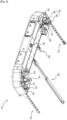
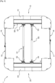
- the mobile cart system 1 illustrated in figures 1 to 8 comprises a first mobile module 10 and a second mobile module 20.
- Each mobile module 10, 20 extends mainly along a longitudinal axis and comprises a chassis 12, 22 equipped with wheels as well as a lifting device 55 adapted to be able to move a aircraft element such as an aircraft engine in at least one vertical direction.
- the first mobile module 10 and the second mobile module 20 are adapted to be able to be controlled in a coordinated manner with each other.
- Each mobile module 10, 20 can be controlled by an operator via a wireless remote control.
- the first mobile module and the second mobile module can be controlled independently of each other or simultaneously, in particular when manipulating an aircraft element using the system according to the invention. That is to say that each mobile module 10, 20 can be controlled alone, independently of the other mobile module (in particular when no aircraft element is loaded on said mobile, but for example for the movement from the mobile module towards the aircraft element to be handled or towards a storage area after handling).
- Each mobile module 10, 20 is energy independent, each mobile module can for example include at least one electric battery.
- the mobile carriage system 1 comprises at least one connecting arm 16, 17 adapted to be able to secure together the chassis of the first module and the chassis of the second module.
- each mobile module comprises a link arm, the first mobile module 10 comprising a first link arm 16 and the second mobile module 20 comprising a second link arm 17.
- the connecting arms 16, 17 make it possible to secure the two mobile modules 10, 20 together by maintaining a constant spacing between the two mobile modules 10, 20, and in particular to avoid their separation while avoiding their coming together. They also make it possible to maintain a fixed relative positioning of one relative to the other as can be seen in the Figure 3 .
- An engine 80 and a transport frame 90 on which the engine rests (or another aircraft element) can be arranged between the first mobile module 10 and the second mobile module 20 as shown in Fig. figure 4 .
- the aircraft element to be manipulated, an aircraft engine 80 in the embodiment shown, is intended to be placed between the first mobile module 10 and the second mobile module 20 of the mobile carriage system.
- the aircraft engine is arranged so that the longitudinal axis of the aircraft engine is oriented parallel to the longitudinal axis of each of the mobile modules 10, 20.
- the orientation of the aircraft engine loaded on the system is different from that illustrated, and for example perpendicular to the longitudinal axis of each of the mobile modules 10, 20.
- each connecting arm 16, 17, 18, 19 extends in a substantially transverse direction, orthogonal to said longitudinal direction of each mobile module 10, 20, each connecting arm 16, 17, 18, 19 being linked to the chassis of the first mobile module 10 or to the chassis of the second module 20 by a pivot connection authorizing rotation around a vertical axis, orthogonal to the direction in which said connecting arm extends.
- the first mobile module 10 comprises two link arms 16, 18.
- the second mobile module 20 comprises two link arms 17, 19.
- the link arm 16 of the first mobile module 10 is fixed to the link arm 19 of the second module 20 by a mechanical connection making it possible to adjust the total length formed by the two connecting arms.
- connection connecting the connecting arms together, after adjustment of the total length, is a complete connection, the two connecting arms assembled two by two each behaving in the same way as a single bar or rod.
- one of the two modules preferably functions as “master”.
- At least one connecting arm 18, 19 comprises a communication cable 70 adapted to allow communication and data transmission between the first mobile module 10 and the second mobile module 20.
- Each communication cable 70 can be arranged inside of the connecting arm (in the case where the connecting arm is formed of a hollow bar for example) or attached to it, for example inside a chute 72 itself fixed along the arm 18 link ( figure 1 ).
- the distal end of the communication cable 72 of the connecting arm 18 is connected to a storage connector 74.
- the connecting arm 16 also includes a chute 73 inside which a communication cable is predisposed (not visible).
- the connecting arm 16 also has several connectors 76 connected to the communication cable arranged inside the chute 73.
- a communication cable of the connecting arm connection 19 of the second mobile module 20 can be connected to the connector 76 whose end will be the closest, depending on the desired adjustment of the distance (spacing) between the two mobile modules 10 and 20.
- each wheel unit 30 comprises two motorized wheels 35, 36, 33, 34.
- the wheels are mounted on a spreader bar 34, 37 so as to allow uniform distribution of the loads between them.
- the coordinated and synchronized rotation in the opposite direction of the wheels 35, 36, 33, 34 allows the autorotation of the wheel unit 30.
- each mobile module 10, 20 also includes two idler wheels 42, 44 ( figure 2 ).
- each mobile module is adapted to be able to be moved in all directions.
- the mobile trolley system comprising the first mobile module and the second mobile module secured together is adapted to be able to be moved in all directions.
- the system and each module can be moved axially (longitudinally or laterally in one direction). transverse) forward or backward, but also by performing an autorotation around a predetermined axis of rotation.
- the system can include safety encoders making it possible to control the relative position of each mobile module (in particular their spacing and the angle they form relative to each other) and thus control them together.
- Each lifting device is adapted to be able to move an aircraft element vertically and by an inclination relative to a lifting plane orthogonal to said vertical direction (displacement in pitch and/or roll independently or combined with movement according to a vertical direction) by combining the coordinated movement of the lifting actuators.
- Each lifting device includes at least one lifting cylinder (hydraulic or electric). In the embodiment of a mobile cart system shown in figures 1 to 8 , it is a crossed scissor lifting device operated using two lifting cylinders. The crossed scissor lifts are visible at the Figure 11 .
- Each lifting device 55 of each mobile module 10, 20 comprises at least one fork 50, 51 extending in a transverse direction.
- each mobile module 10, 20 comprises a fork 50, 51 and a device for locking the fork of the other mobile module.
- the first mobile module 10 comprises a fork 50 fixed to a rail 58 via a first fixing device 53, as well as a second fixing device 57 of a locking “male” receiving end 56 adapted to receive the end of a fork 51 of the second mobile module 20.
- the second mobile module 20 comprises a fork 51 fixed to a rail via a first fixing device 52, as well as a second fixing device 54 of a locking "male" receiving end adapted to receive the “female” end 59 of the fork 50 of the first mobile module 10.
- the rail 58 extends longitudinally on an internal face of the chassis of a mobile module.
- Each fork and each fixing device can slide in translation along said rail 58 of the first mobile module or an identical rail (not shown) of the second mobile module. Locking could also alternatively be carried out between the respective ends of four forks (two by two).
- the connecting arms 16, 17, 18, 19 that is to say in particular in the configuration of moving or manipulating an element aircraft
- the connecting arms and the forks extend in directions substantially parallel to each other.
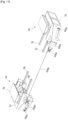
- the connecting arm arranged in front or behind the mobile modules 10, 20 is replaced by at least one connection cable 1000.
- at least one mobile module 10, 20 comprises at least one connection cable 1000 which is arranged in front of the mobile trolley system 1. It should be noted that for reasons of clarity the connecting arm 16, 17 arranged at the rear of each module 10, 20 is not shown.
- each mobile module 10, 20 comprises a connection cable 1000 configured to be connected to the other mobile module 10, 20.
- each mobile module 10, 20 which comprises a connection cable 1000 can include a means of managing the storage and deployment of the connection cable 1000.
- each mobile module 10, 20 may include a reel 1001.
- the reel 1001 has locking means making it possible to maintain the constant spacing between the two mobile modules 10, 20.
- the reel 1001 is housed in the chassis 12, 22 of each mobile module 10, 20.
- the chassis 12, 22 has a gaping opening which allows the connection cable 1000 to exit or enter into the housing of the reel 1001.
- each module 10, 20 may include a pulley 1002 to facilitate the winding and unwinding of the connecting cable 1000.
- the pulley 1002 is offset relative to the chassis 12, 22 of each mobile module 10, 20.
- a larger space is generated between the mobile modules 10, 20 in order to load larger aircraft elements.
- each mobile module 10, 20 may comprise an offset arm 1003 which carries the pulley 1002 at its free end.
- the offset arm 1003 is coupled to the chassis using a pivot connection. The offset arm 1003 can thus be folded to improve the compactness of the mobile trolley system 1 or deployed when loading an aircraft element in order to adapt to the dimensions of the aircraft element.
- the pulley 1002 can also be rotatably mounted relative to the offset arm 1003. This ensures adjustment of the spacing of the two mobile modules 10, 20 relative to the aircraft element to be loaded.
- Each module 10, 20 comprises a locking means for a connecting cable 1000 whose reel 1001 is located in the other module 10, 20.
- the locking means is arranged on the pulley 1002.
- the locking means can be constituted by a pinout.
- connection cable 1000 housed in a first mobile module is attached to the second mobile module. If each mobile module 10, 20 includes a connection cable 1000, the two connection cables 1000 are attached between the two mobile modules.
- the distance between the two mobile modules 10, 20 adjusted by controlling one or both mobile modules. The distance is adjusted according to the dimensions of the aircraft element and/or its transport frame. Then, the locking means of each reel 1001 is engaged in order to maintain the spacing between the two modules 10, 20 constant.
- each module 10, 20 is also coupled together.
- the spacing between the two mobile modules is adjusted while the forks 50, 51 are inserted into the sleeves 900 of the transport frame 90.
- the mobile trolley system according to the embodiment shown in figures 1 to 8 can thus be adapted to all sizes of engines and transport frames depending on the spacing between the first mobile module and the second mobile module, the spacing of the forks (parallel to each other), the position of the forks on each mobile module and the height of the forks. These adjustments also make it possible to manage the position of the center of gravity of the load represented by the aircraft element.
- Each fork can be at least partly retractable so as to be able to adjust its length.
- Each fork can extend and fold telescopically, for example.
- Each lifting device of the mobile cart system can also allow a second level of adjustment of the position of the forks according to the vertical.
- each fork is in a position corresponding to the lowest position of the forks and the usual position for picking up a load using the forks. In this position the distance between the upper face of each fork and an upper face of the lifting device is maximum. This position has the advantage of allowing a load to be picked up using the forks as close to the ground as possible when necessary.
- each fixing device 53, 57 to the rail 58 also includes a stop rocker 101 which can be actuated using a stop lever 102.
- the lifting device is actuated so as to raise the forks until reaching a predetermined position illustrated in figure 5 on which the stop lever 102 has been moved in order to modify the position of the stop rocker 101, one end of which rests on a part 101a, called fork cam, so as to allow the fixing device 53 to move vertically along a slide 104 until reaching a low stop position shown in Figure 6 reached after descent of the lifting device as illustrated by arrow 106 in Figure 6 .
- a locking lever 105 can be tilted (see figure 7 after tilting this locking lever 105) and allow the forks to be lifted in this position upwards as illustrated by arrow 107 on the figure 7 . This makes it possible to offer a certain additional play along the vertical axis which is particularly useful and appreciable during the installation and/or removal of the aircraft element.
- each fork 50, 51 can extend longitudinally to a free end 500.
- each fork 50, 51 extends between a stirrup part 501 and its free end 500.
- the forks 50, 51 can be made by mechanically welded assembly with mortise-tenons oriented so as to avoid heavy welding.
- each fork 50, 51 is pivotally mounted to the fixing device 53, 57. This allows the deployment and folding of the forks 50, 51 parallel to the chassis 12, 22 of the mobile module 10, 20.
- the forks 50, 51 are deployed for the purpose of supporting an aircraft element 80 and folded for storage and movement of the mobile trolley system 1.
- the stirrup part 501 makes it possible to couple the fork 50, 51 to the fixing device 53, 57.
- Each module 10, 20 comprises a coupling part 502 on which the stirrup part 501 is pivotally mounted.
- the coupling part 502 is mounted on the fixing device 53, 57 of each module 10, 20.
- the articulation which constitutes the stirrup part 501 and the coupling part 502 allows the folding and deployment of the forks 50, 51.
- each fork 50, 51 is configured to be positioned cantilevered, for example, in a sheath 900 of the transport frame 90. Indeed, once the fork 50, 51 is introduced into the sheath 900, the free end 500 bears on a lower wall of the sheath 900. At the same time, at the inlet 901 of the sheath 900, the body of the fork 50, 51 bears on an upper wall of the sheath 900.
- the carriage system mobile has four identical forks 50, 51.
- each fork 50, 51 of two mobile modules 10, 20 are not butted together, in particular, each fork 50, 51 arcs butts between the two support points that the fork 50, 51 takes on the sheath 900 in which said fork 50, 51 is introduced.
- each fork 50, 51 comprises at least one support pad 503.
- the support pad 503 ensures better grip when loading the aircraft element.
- each support pad 503 may include a system for adjusting the spatial orientation of the support pad 503 along at least one axis.
- the support pad 503 orientable along at least one axis improves the support of the aircraft element, for example, through a sheath 900 of the transport frame 90. It is thus possible to orient the pad support 503 depending on the support surface of the fork 50, 51 and to prevent support on an inadequate surface such as an edge.
- the support pad 503 can be pivotally mounted on an axis 504 with limited clearance.
- the axis 504 is perpendicular to the longitudinal direction of the forks 50, 51.
- each fork 50, 51 comprises two support pads 503.
- a first support pad 503 is arranged at the free end of the fork 500.
- the first support pad 503 is arranged on the lower face of the fork 50, 51.
- a second support shoe 503 is arranged at a determined distance from the first support shoe 503.
- the second support shoe 503 can be arranged at a distance between 500 mm and 1000 mm of the first support pad 503.
- the second support pad 503 is provided on the upper face of the fork 50, 51.
- the first support pad 503 bears on the lower wall of the sheath 900 then that the second support pad 503 bears on the upper wall of the sheath 900 at the inlet 901 thereof.
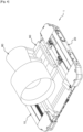
- the fork 50, 51 each mobile module 10, 20 of figures 9 and 10 are coupled to the fixing devices 53, 57 in the same way as the forks 50, 51 of the figures 1 to 8 .
- couple the mode of realization of the figures 9 and 10 and the method of carrying out the Figure 11 makes it possible to generate more available space between the two mobile modules 10, 20 in order to adapt to larger aircraft elements or transport frames 90.
- the methods of carrying out the figures 9, 10 And 11 are also compatible with the embodiments of the figures 1 to 8 .
- Each mobile module 10, 20 comprises three flexibility cylinders 61, 62, 63.
- Two flexibility cylinders 61, 63 are arranged at each of the longitudinal ends of the chassis of the first mobile module 10 and the third cylinder 62 is arranged at the level of a central portion of the chassis 12 of the first mobile module 10.
- Each flexibility cylinder 61, 62, 63 can be hydraulic or electric.
- Each flexibility cylinder can be associated with a carrier ball plate so as to allow, for example, a travel in a substantially horizontal plane of approximately 50 mm.
- each flexibility cylinder also makes it possible to adjust the attitude and inclination of each mobile module.
- the mobile carriage system comprises a rolling plate 110 placed on and in contact with the balls of a ball plate 112 arranged opposite each lifting cylinder 114.
- a centering cylinder 117 is associated with this device and also includes a centering block 116 adapted to be able to move in a centering cone 115.
- the locking axis makes it possible to completely block or control the authorized range of movement of the ball plate 112 on the rolling plate 110. This axis is controlled by a gear motor with angle gear.
- the centering cone 115 matches the shape of the centering block 116, thus blocking any relative movement between the ball plate 112 and the rolling plate 110.
- the centering block 116 descends in the centering cone 115 and the range of movement authorized in the plane increases.
- the system can also include force sensors making it possible to ensure that the mobile trolley system is not overloaded and/or to control, for example, the application forces between the engine and the aircraft.
- each mobile module can have at least two lifting rings, in particular three lifting rings distributed at the longitudinal ends and in the center, in order to be able to move it easily using an overhead crane. . It is also possible to move each mobile module 10, 20 with a forklift.
- the mobile trolley system according to the embodiment shown in figures 1 to 8 has for example dimensions such that it has a length of around 6.40 meters, a width of around 3.55 meters and a height of around 0.80 meters when the first mobile module and the second mobile module are arranged side by side (without connecting arms between them and with their forks not deployed) according to their length.
- the lifting device can also be used after the flexibility cylinders have been deployed.
- each of the flexibility cylinders 61, 62, 63 comes into contact with the ground.
- the motorized wheels 35, 36, 33, 24 can be blocked, in particular prior to the deployment of the flexibility cylinders 61, 62, 63.
- each fork 50 of the first mobile module is locked with the second mobile module and each fork 51 of the second mobile module is locked with the first mobile module.
- the locking of the forks can in particular be automatic, for example via a system with springs thanks to which the locking of the forks is automatic as soon as a mass (that is to say that of an aircraft element and a possible transport frame) is supported by the forks so as not to require manual intervention by an operator, nor electrical control.
Landscapes
- Engineering & Computer Science (AREA)
- Transportation (AREA)
- Manufacturing & Machinery (AREA)
- Aviation & Aerospace Engineering (AREA)
- Mechanical Engineering (AREA)
- General Engineering & Computer Science (AREA)
- Handcart (AREA)
- Transmission Devices (AREA)
Claims (15)
- Beweglich Schlittensystem (1) zum Bewegen eines Flugzeugelements (80), die ein Flugzeugmotor ist, das System umfassend:- ein erstes bewegliches Modul (10) und ein zweites bewegliches Modul (20), wobei sich jedes bewegliche Modul (10, 20) hauptsächlich entlang einer Längsachse erstreckt und Folgendes umfasst:dadurch gekennzeichnet, dass das erste bewegliche Modul (10) und das zweite bewegliche Modul (20) angepasst sind, um unabhängig voneinander und gleichzeitig koordiniert miteinander gesteuert und bewegt werden zu können, wenn sie mittels mindestens eines Verbindungsarms (16, 17, 18, 19) verbunden werden zu können, und wobei die Hebevorrichtung (55) von jedem beweglichen Modul (10, 20) angepasst ist, um das Flugzeugelement (80) vertikal und durch eine Neigung in Bezug auf eine Hebeebene orthogonal zu der vertikalen Richtung bewegen zu können.o einen Rahmen (12, 22), der mit mindestens drei Rädern (32, 33, 35, 36, 42, 44) ausgestattet ist,o eine Hebevorrichtung (55), die angepasst ist, um das Flugzeugelement (80) mindestens in einer vertikalen Richtung bewegen zu können, die Hebevorrichtung (55) von jedem beweglichen Modul (10, 20) umfassend mindestens eine Gabel (50, 51), die sich in einer Querrichtung erstreckt, die orthogonal zu der Längsachse von jedem Modul (10, 20) ist,o mindestens einen Verbindungsarm (16, 17, 18, 19), der angepasst ist, um den Rahmen des ersten Moduls und den Rahmen des zweiten Moduls fest miteinander verbinden zu können,
- System nach Anspruch 1, wobei jedes bewegliche Modul (10, 20) eine Schiene (58) umfasst, die sich in Längsrichtung erstreckt, wobei die Gabel (50, 51) von jedem beweglichen Modul (10, 20) über eine Befestigungsvorrichtung (52, 53) an der Schiene (58) des beweglichen Moduls (10, 20) befestigt ist, wobei die Gabel (50, 51) und die Befestigungsvorrichtung (52, 53) translatorisch verschiebbar entlang der Schiene (58) an jedem beweglichen Modul (10, 20) montiert sind.
- System nach Anspruch 2, wobei jede Befestigungsvorrichtung (53, 57) an der Schiene (58) auch eine Anschlagkippeinrichtung (101) umfasst, die mittels eines Anschlaghebels (102) betätigt wird.
- System nach einem der Ansprüche 1 bis 3, wobei jede Gabel (50, 51) mindestens eine Auflagekufe (503) umfasst.
- System nach Anspruch 4, wobei jede Auflagekufe (503) ein Einstellsystem der räumlichen Ausrichtung der Auflagekufe (503) entlang mindestens einer Achse umfasst.
- System nach einem der Ansprüche 1 bis 5, wobei jedes bewegliche Modul (10, 20) mindestens zwei Zylinder (61, 62, 63), sogenannte Flexibilitätszylinder, umfasst, wobei jeder Flexibilitätszylinder mit mindestens einer Tragkugelplatte (112) assoziiert ist, um mindestens eine Translation des Flugzeugelements in einer horizontalen Ebene, im Wesentlichen orthogonal zu der vertikalen Richtung, in Bezug auf jedes bewegliche Modul zu ermöglichen.
- System nach einem der Ansprüche 1 bis 6, wobei die Hebevorrichtung (55) eine Kreuzschere umfasst, die mittels zwei Hebezylindern betätigt wird.
- System nach einem der Ansprüche 1 bis 7, wobei die Hebevorrichtung (55) mindestens einen Hebezylinder umfasst.
- System nach einem der Ansprüche 1 bis 8, wobei mindestens das erste bewegliche Modul (10) Folgendes umfasst:- ein Verbindungskabel (1000), das konfiguriert ist, um mit dem zweiten mobilen Modul (20) verbunden zu werden, und- eine Handhabungseinrichtung der Aufbewahrung und des Einsatzes des Verbindungskabels (1000).
- System nach einem der Ansprüche 1 bis 9, wobei der Verbindungsarm (16, 17, 18, 19) mindestens eines mobilen Moduls (10, 20) ein Kommunikationskabel (70) umfasst, das angepasst ist, um eine Datenübertragung zwischen dem ersten mobilen Modul und dem zweiten mobilen Modul zu ermöglichen, und sich jeder Verbindungsarm (16, 17) in einer Querrichtung erstreckt, die orthogonal zu der Längsrichtung des mobilen Moduls ist.
- System nach einem der Ansprüche 1 bis 10, wobei jeder Verbindungsarm (16, 17) durch eine Schwenkverbindung mit mindestens einem von dem ersten beweglichen Modul (10) und dem zweiten beweglichen Modul (20) verbunden ist.
- System nach einem der Ansprüche 1 bis 11, das zwei Verbindungsarme (16, 17, 18, 19) umfasst, wobei ein erster Verbindungsarm (16) an dem Rahmen des ersten beweglichen Moduls (10) befestigt ist und ein zweiter Verbindungsarm (17) an dem Rahmen des zweiten beweglichen Moduls (20) befestigt ist.
- System nach einem der Ansprüche 1 bis 12, wobei der Rahmen (12, 22) von jedem mobilen Modul (10, 20) mit mindestens zwei angetriebenen Rädern (32, 33, 35, 36) ausgestattet ist.
- Verfahren zum Einsetzen eines Systems nach einem der Ansprüche 1 bis 13,
wobei in dem Verfahren:- das erste bewegliche Modul (10) gesteuert wird, um mindestens eine Gabel (50) des ersten beweglichen Moduls in Gabeln eines Transportgestells einzuführen, wobei das Transportgestell angepasst ist, um das Flugzeugelement (80) aufnehmen zu können, dann- das zweite bewegliche Modul (20) gesteuert wird, um mindestens eine Gabel (51) des zweiten beweglichen Moduls in die Gabeln des Transportgestells einzuführen,- der Rahmen des ersten Moduls und der Rahmen des zweiten beweglichen Moduls mittels mindestens eines Verbindungsarms (16, 17, 18, 19) fest miteinander verbunden werden, dann- das erste bewegliche Modul und das zweite bewegliche Modul auf untereinander koordinierte Weise gesteuert werden,- das Flugzeugelement (80) mittels der Hebevorrichtung von jedem beweglichen Modul mindestens in einer vertikalen Richtung bewegt wird. - Verfahren nach Anspruch 14, wobei nach Bewegen des Flugzeugelements (80) mindestens in einer vertikalen Richtung mittels der Hebevorrichtung Zylinder (61, 62, 63) zur Flexibilität einer Hebevorrichtung von jedem beweglichen Modul (10, 20) ausgefahren werden.
Applications Claiming Priority (1)
| Application Number | Priority Date | Filing Date | Title |
|---|---|---|---|
| FR2101924A FR3120230B1 (fr) | 2021-02-26 | 2021-02-26 | Système de chariot mobile et procédé de mise en œuvre d’un système de chariot mobile |
Publications (2)
| Publication Number | Publication Date |
|---|---|
| EP4049936A1 EP4049936A1 (de) | 2022-08-31 |
| EP4049936B1 true EP4049936B1 (de) | 2024-06-26 |
Family
ID=75690469
Family Applications (1)
| Application Number | Title | Priority Date | Filing Date |
|---|---|---|---|
| EP22159033.4A Active EP4049936B1 (de) | 2021-02-26 | 2022-02-25 | System mit einem beweglichen schlitten und verfahren zur anwendung eines solchen systems mit beweglichem schlitten |
Country Status (6)
| Country | Link |
|---|---|
| US (1) | US11713139B2 (de) |
| EP (1) | EP4049936B1 (de) |
| CN (1) | CN115042993A (de) |
| ES (1) | ES2989035T3 (de) |
| FR (1) | FR3120230B1 (de) |
| PT (1) | PT4049936T (de) |
Families Citing this family (4)
| Publication number | Priority date | Publication date | Assignee | Title |
|---|---|---|---|---|
| CN116198741B (zh) * | 2023-02-28 | 2024-09-03 | 中航成飞民用飞机有限责任公司 | 飞机门框壁板在不开敞区域的上架装置及其定位方法 |
| CN116588344B (zh) * | 2023-06-16 | 2025-08-12 | 湖南航天宏图无人机系统有限公司 | 一种多旋翼无人机机臂的安装定位夹具 |
| CN118701458A (zh) * | 2024-07-08 | 2024-09-27 | 中集运载科技有限公司 | 多模块组装的物流框架箱 |
| CN118992114B (zh) * | 2024-09-12 | 2025-03-25 | 哈尔滨远驰航空装备有限公司 | 一种直升机观瞄系统拆装用的托架装置 |
Family Cites Families (13)
| Publication number | Priority date | Publication date | Assignee | Title |
|---|---|---|---|---|
| DE9203607U1 (de) * | 1992-03-15 | 1992-07-23 | Franke GmbH, 21220 Seevetal | Allseitig rangierbares, gleisloses Flurfördergerät mit teleskopierbarem Trägergestell |
| US6170141B1 (en) * | 1998-09-25 | 2001-01-09 | Stanley Aviation Corporation | Shipping system for jet aircraft engine and method of installing and removing jet aircraft engine |
| FR2848528A1 (fr) * | 2002-12-12 | 2004-06-18 | Alkan Sa | Procede et appareillage pour le montage des trains d'atterrissage sur des aeronefs |
| US20070110552A1 (en) * | 2005-11-15 | 2007-05-17 | Groves Oliver J | Aircraft landing gear loader |
| US7913390B2 (en) * | 2006-02-16 | 2011-03-29 | The Boeing Company | Transport tool |
| GB2480673B (en) * | 2010-05-28 | 2014-10-29 | Belron Hungary Kft Zug Branch | Pallet container |
| DE102015214667B4 (de) * | 2015-07-31 | 2020-11-19 | MTU Aero Engines AG | Montagesystem zum Montieren, Demontieren und/oder Warten einer Gasturbine |
| CN207389588U (zh) * | 2017-04-17 | 2018-05-22 | 闵好年 | 一种模块化飞机综合维护平台 |
| DE102018115455A1 (de) * | 2018-06-27 | 2020-01-02 | HYDRO Holding KG | Vorrichtung zum Ein- und Ausbau von Flugzeugfahrwerken |
| CN109131932B (zh) * | 2018-08-09 | 2022-02-22 | 中国飞机强度研究所 | 飞机姿态调整装置及落震试验系统 |
| US10472095B1 (en) * | 2018-09-07 | 2019-11-12 | The Boeing Company | Mobile fixture apparatuses and methods |
| CN209193464U (zh) * | 2018-11-03 | 2019-08-02 | 上海威克特航空地面设备有限公司 | 一种飞机主起落架拆装托架装置 |
| CN110002002B (zh) * | 2019-04-24 | 2024-01-16 | 新乡市永安机械设备有限公司 | 一种直升飞机用折叠托架 |
-
2021
- 2021-02-26 FR FR2101924A patent/FR3120230B1/fr active Active
-
2022
- 2022-02-25 EP EP22159033.4A patent/EP4049936B1/de active Active
- 2022-02-25 CN CN202210176841.2A patent/CN115042993A/zh active Pending
- 2022-02-25 PT PT221590334T patent/PT4049936T/pt unknown
- 2022-02-25 ES ES22159033T patent/ES2989035T3/es active Active
- 2022-02-25 US US17/681,679 patent/US11713139B2/en active Active
Also Published As
| Publication number | Publication date |
|---|---|
| FR3120230A1 (fr) | 2022-09-02 |
| US20220388688A1 (en) | 2022-12-08 |
| US11713139B2 (en) | 2023-08-01 |
| FR3120230B1 (fr) | 2024-03-01 |
| CN115042993A (zh) | 2022-09-13 |
| PT4049936T (pt) | 2024-09-05 |
| EP4049936A1 (de) | 2022-08-31 |
| ES2989035T3 (es) | 2024-11-25 |
Similar Documents
| Publication | Publication Date | Title |
|---|---|---|
| EP4049936B1 (de) | System mit einem beweglichen schlitten und verfahren zur anwendung eines solchen systems mit beweglichem schlitten | |
| EP0147246B1 (de) | Transportgestell für Turbomaschine | |
| EP3455156B1 (de) | Bewegliche basis und verfahren zum transport einer ausrüstung | |
| FR2891245A1 (fr) | Procede de montage d'un moteur d'aeronef sur une structure rigide d'un mat d'accrochage du moteur | |
| EP3347526A2 (de) | Bohrmaschine | |
| EP1677065B1 (de) | Mobiles Waffensystem für Kraftwagen | |
| FR3058987A1 (fr) | Organe et chariot pour la depose, le transport, et la maintenance, d'une turbomachine | |
| CA2067439C (fr) | Nacelle heliportee et procede de remplacement d'un manchon sur un cable aerien | |
| EP3949925B1 (de) | Abnehmbares elektrisches antriebssystem für ein rollendes objekt, gleichzeitiges und kombiniertes greifen und entfernen der räder in längsrichtung | |
| WO2023067005A1 (fr) | Dispositif de manutention et de transfert d'un moteur d'aeronef, systeme et procédé d'arrimage associé | |
| EP4157188B1 (de) | Abnehmbares elektronisches antriebssystem für ein rollendes objekt mit automatischer richtungsblockierung | |
| EP3070203B1 (de) | Be-, entlade- und aufsetzsystem einer schienenweiche auf ein bahngleis | |
| EP2993266B1 (de) | System und verfahren zum transport einer ausrüstung | |
| FR3015915B1 (fr) | Chassis de vehicule omnidirectionnel comportant des corps de chassis deplacables l'un par rapport a l'autre | |
| FR3058392A1 (fr) | Chariot et procede de transport d'un moteur d'aeronef | |
| EP0589792B1 (de) | Handhabungseinrichtung für Rohrbündel von Wärmetauschern | |
| FR3132907A1 (fr) | Portique de levage et procede de montage associe | |
| FR2504904A1 (fr) | Procede de manutention et d'installation d'un materiel aux fins de sa mise en oeuvre apres transport et installation sur son site d'utilisation | |
| FR2645521A1 (fr) | Plate-forme elevatrice mobile constituant un support pour une camera | |
| FR3041091A1 (fr) | Dispositif de transport d'une torpille depuis un chariot d'acheminement vers un tube de lancement | |
| FR2848200A1 (fr) | Dispositif de manutention d'une charge | |
| EP4157187A1 (de) | Abnehmbares elektrisches antriebssystem für ein rollobjekt mit mitteln zum kombinierten und gleichzeitigen greifen und heben | |
| WO2025068663A1 (fr) | Dispositif de manutention d'un élément d'un aéronef et ensemble de manutention doté d'un tel dispositif | |
| FR3079828A1 (fr) | Outil de levage et de transport d'un equipement au sol | |
| FR2683517A1 (fr) | Plate-forme elevatrice a paires de bras articules. |
Legal Events
| Date | Code | Title | Description |
|---|---|---|---|
| PUAI | Public reference made under article 153(3) epc to a published international application that has entered the european phase |
Free format text: ORIGINAL CODE: 0009012 |
|
| STAA | Information on the status of an ep patent application or granted ep patent |
Free format text: STATUS: THE APPLICATION HAS BEEN PUBLISHED |
|
| AK | Designated contracting states |
Kind code of ref document: A1 Designated state(s): AL AT BE BG CH CY CZ DE DK EE ES FI FR GB GR HR HU IE IS IT LI LT LU LV MC MK MT NL NO PL PT RO RS SE SI SK SM TR |
|
| STAA | Information on the status of an ep patent application or granted ep patent |
Free format text: STATUS: REQUEST FOR EXAMINATION WAS MADE |
|
| 17P | Request for examination filed |
Effective date: 20230223 |
|
| RBV | Designated contracting states (corrected) |
Designated state(s): AL AT BE BG CH CY CZ DE DK EE ES FI FR GB GR HR HU IE IS IT LI LT LU LV MC MK MT NL NO PL PT RO RS SE SI SK SM TR |
|
| P01 | Opt-out of the competence of the unified patent court (upc) registered |
Effective date: 20230530 |
|
| GRAP | Despatch of communication of intention to grant a patent |
Free format text: ORIGINAL CODE: EPIDOSNIGR1 |
|
| STAA | Information on the status of an ep patent application or granted ep patent |
Free format text: STATUS: GRANT OF PATENT IS INTENDED |
|
| RIC1 | Information provided on ipc code assigned before grant |
Ipc: F01D 5/00 20060101ALI20240111BHEP Ipc: F01D 25/28 20060101ALI20240111BHEP Ipc: B64F 5/50 20170101AFI20240111BHEP |
|
| INTG | Intention to grant announced |
Effective date: 20240202 |
|
| GRAS | Grant fee paid |
Free format text: ORIGINAL CODE: EPIDOSNIGR3 |
|
| GRAA | (expected) grant |
Free format text: ORIGINAL CODE: 0009210 |
|
| STAA | Information on the status of an ep patent application or granted ep patent |
Free format text: STATUS: THE PATENT HAS BEEN GRANTED |
|
| AK | Designated contracting states |
Kind code of ref document: B1 Designated state(s): AL AT BE BG CH CY CZ DE DK EE ES FI FR GB GR HR HU IE IS IT LI LT LU LV MC MK MT NL NO PL PT RO RS SE SI SK SM TR |
|
| REG | Reference to a national code |
Ref country code: GB Ref legal event code: FG4D Free format text: NOT ENGLISH |
|
| REG | Reference to a national code |
Ref country code: CH Ref legal event code: EP |
|
| REG | Reference to a national code |
Ref country code: DE Ref legal event code: R096 Ref document number: 602022004080 Country of ref document: DE |
|
| REG | Reference to a national code |
Ref country code: PT Ref legal event code: SC4A Ref document number: 4049936 Country of ref document: PT Date of ref document: 20240905 Kind code of ref document: T Free format text: AVAILABILITY OF NATIONAL TRANSLATION Effective date: 20240830 |
|
| REG | Reference to a national code |
Ref country code: NL Ref legal event code: FP |
|
| PG25 | Lapsed in a contracting state [announced via postgrant information from national office to epo] |
Ref country code: BG Free format text: LAPSE BECAUSE OF FAILURE TO SUBMIT A TRANSLATION OF THE DESCRIPTION OR TO PAY THE FEE WITHIN THE PRESCRIBED TIME-LIMIT Effective date: 20240626 |
|
| PG25 | Lapsed in a contracting state [announced via postgrant information from national office to epo] |
Ref country code: HR Free format text: LAPSE BECAUSE OF FAILURE TO SUBMIT A TRANSLATION OF THE DESCRIPTION OR TO PAY THE FEE WITHIN THE PRESCRIBED TIME-LIMIT Effective date: 20240626 Ref country code: FI Free format text: LAPSE BECAUSE OF FAILURE TO SUBMIT A TRANSLATION OF THE DESCRIPTION OR TO PAY THE FEE WITHIN THE PRESCRIBED TIME-LIMIT Effective date: 20240626 |
|
| REG | Reference to a national code |
Ref country code: LT Ref legal event code: MG9D |
|
| PG25 | Lapsed in a contracting state [announced via postgrant information from national office to epo] |
Ref country code: GR Free format text: LAPSE BECAUSE OF FAILURE TO SUBMIT A TRANSLATION OF THE DESCRIPTION OR TO PAY THE FEE WITHIN THE PRESCRIBED TIME-LIMIT Effective date: 20240927 |
|
| PG25 | Lapsed in a contracting state [announced via postgrant information from national office to epo] |
Ref country code: LV Free format text: LAPSE BECAUSE OF FAILURE TO SUBMIT A TRANSLATION OF THE DESCRIPTION OR TO PAY THE FEE WITHIN THE PRESCRIBED TIME-LIMIT Effective date: 20240626 |
|
| PG25 | Lapsed in a contracting state [announced via postgrant information from national office to epo] |
Ref country code: NO Free format text: LAPSE BECAUSE OF FAILURE TO SUBMIT A TRANSLATION OF THE DESCRIPTION OR TO PAY THE FEE WITHIN THE PRESCRIBED TIME-LIMIT Effective date: 20240926 Ref country code: LV Free format text: LAPSE BECAUSE OF FAILURE TO SUBMIT A TRANSLATION OF THE DESCRIPTION OR TO PAY THE FEE WITHIN THE PRESCRIBED TIME-LIMIT Effective date: 20240626 Ref country code: HR Free format text: LAPSE BECAUSE OF FAILURE TO SUBMIT A TRANSLATION OF THE DESCRIPTION OR TO PAY THE FEE WITHIN THE PRESCRIBED TIME-LIMIT Effective date: 20240626 Ref country code: GR Free format text: LAPSE BECAUSE OF FAILURE TO SUBMIT A TRANSLATION OF THE DESCRIPTION OR TO PAY THE FEE WITHIN THE PRESCRIBED TIME-LIMIT Effective date: 20240927 Ref country code: FI Free format text: LAPSE BECAUSE OF FAILURE TO SUBMIT A TRANSLATION OF THE DESCRIPTION OR TO PAY THE FEE WITHIN THE PRESCRIBED TIME-LIMIT Effective date: 20240626 Ref country code: BG Free format text: LAPSE BECAUSE OF FAILURE TO SUBMIT A TRANSLATION OF THE DESCRIPTION OR TO PAY THE FEE WITHIN THE PRESCRIBED TIME-LIMIT Effective date: 20240626 Ref country code: RS Free format text: LAPSE BECAUSE OF FAILURE TO SUBMIT A TRANSLATION OF THE DESCRIPTION OR TO PAY THE FEE WITHIN THE PRESCRIBED TIME-LIMIT Effective date: 20240926 |
|
| REG | Reference to a national code |
Ref country code: AT Ref legal event code: MK05 Ref document number: 1697528 Country of ref document: AT Kind code of ref document: T Effective date: 20240626 |
|
| REG | Reference to a national code |
Ref country code: ES Ref legal event code: FG2A Ref document number: 2989035 Country of ref document: ES Kind code of ref document: T3 Effective date: 20241125 |
|
| PG25 | Lapsed in a contracting state [announced via postgrant information from national office to epo] |
Ref country code: PL Free format text: LAPSE BECAUSE OF FAILURE TO SUBMIT A TRANSLATION OF THE DESCRIPTION OR TO PAY THE FEE WITHIN THE PRESCRIBED TIME-LIMIT Effective date: 20240626 |
|
| PG25 | Lapsed in a contracting state [announced via postgrant information from national office to epo] |
Ref country code: EE Free format text: LAPSE BECAUSE OF FAILURE TO SUBMIT A TRANSLATION OF THE DESCRIPTION OR TO PAY THE FEE WITHIN THE PRESCRIBED TIME-LIMIT Effective date: 20240626 |
|
| PG25 | Lapsed in a contracting state [announced via postgrant information from national office to epo] |
Ref country code: IS Free format text: LAPSE BECAUSE OF FAILURE TO SUBMIT A TRANSLATION OF THE DESCRIPTION OR TO PAY THE FEE WITHIN THE PRESCRIBED TIME-LIMIT Effective date: 20241026 Ref country code: AT Free format text: LAPSE BECAUSE OF FAILURE TO SUBMIT A TRANSLATION OF THE DESCRIPTION OR TO PAY THE FEE WITHIN THE PRESCRIBED TIME-LIMIT Effective date: 20240626 |
|
| PG25 | Lapsed in a contracting state [announced via postgrant information from national office to epo] |
Ref country code: CZ Free format text: LAPSE BECAUSE OF FAILURE TO SUBMIT A TRANSLATION OF THE DESCRIPTION OR TO PAY THE FEE WITHIN THE PRESCRIBED TIME-LIMIT Effective date: 20240626 |
|
| PG25 | Lapsed in a contracting state [announced via postgrant information from national office to epo] |
Ref country code: RO Free format text: LAPSE BECAUSE OF FAILURE TO SUBMIT A TRANSLATION OF THE DESCRIPTION OR TO PAY THE FEE WITHIN THE PRESCRIBED TIME-LIMIT Effective date: 20240626 Ref country code: SK Free format text: LAPSE BECAUSE OF FAILURE TO SUBMIT A TRANSLATION OF THE DESCRIPTION OR TO PAY THE FEE WITHIN THE PRESCRIBED TIME-LIMIT Effective date: 20240626 |
|
| PG25 | Lapsed in a contracting state [announced via postgrant information from national office to epo] |
Ref country code: SM Free format text: LAPSE BECAUSE OF FAILURE TO SUBMIT A TRANSLATION OF THE DESCRIPTION OR TO PAY THE FEE WITHIN THE PRESCRIBED TIME-LIMIT Effective date: 20240626 |
|
| PG25 | Lapsed in a contracting state [announced via postgrant information from national office to epo] |
Ref country code: SM Free format text: LAPSE BECAUSE OF FAILURE TO SUBMIT A TRANSLATION OF THE DESCRIPTION OR TO PAY THE FEE WITHIN THE PRESCRIBED TIME-LIMIT Effective date: 20240626 Ref country code: SK Free format text: LAPSE BECAUSE OF FAILURE TO SUBMIT A TRANSLATION OF THE DESCRIPTION OR TO PAY THE FEE WITHIN THE PRESCRIBED TIME-LIMIT Effective date: 20240626 Ref country code: RO Free format text: LAPSE BECAUSE OF FAILURE TO SUBMIT A TRANSLATION OF THE DESCRIPTION OR TO PAY THE FEE WITHIN THE PRESCRIBED TIME-LIMIT Effective date: 20240626 Ref country code: PL Free format text: LAPSE BECAUSE OF FAILURE TO SUBMIT A TRANSLATION OF THE DESCRIPTION OR TO PAY THE FEE WITHIN THE PRESCRIBED TIME-LIMIT Effective date: 20240626 Ref country code: IS Free format text: LAPSE BECAUSE OF FAILURE TO SUBMIT A TRANSLATION OF THE DESCRIPTION OR TO PAY THE FEE WITHIN THE PRESCRIBED TIME-LIMIT Effective date: 20241026 Ref country code: EE Free format text: LAPSE BECAUSE OF FAILURE TO SUBMIT A TRANSLATION OF THE DESCRIPTION OR TO PAY THE FEE WITHIN THE PRESCRIBED TIME-LIMIT Effective date: 20240626 Ref country code: CZ Free format text: LAPSE BECAUSE OF FAILURE TO SUBMIT A TRANSLATION OF THE DESCRIPTION OR TO PAY THE FEE WITHIN THE PRESCRIBED TIME-LIMIT Effective date: 20240626 Ref country code: AT Free format text: LAPSE BECAUSE OF FAILURE TO SUBMIT A TRANSLATION OF THE DESCRIPTION OR TO PAY THE FEE WITHIN THE PRESCRIBED TIME-LIMIT Effective date: 20240626 |
|
| REG | Reference to a national code |
Ref country code: DE Ref legal event code: R097 Ref document number: 602022004080 Country of ref document: DE |
|
| PG25 | Lapsed in a contracting state [announced via postgrant information from national office to epo] |
Ref country code: DK Free format text: LAPSE BECAUSE OF FAILURE TO SUBMIT A TRANSLATION OF THE DESCRIPTION OR TO PAY THE FEE WITHIN THE PRESCRIBED TIME-LIMIT Effective date: 20240626 |
|
| PLBE | No opposition filed within time limit |
Free format text: ORIGINAL CODE: 0009261 |
|
| STAA | Information on the status of an ep patent application or granted ep patent |
Free format text: STATUS: NO OPPOSITION FILED WITHIN TIME LIMIT |
|
| 26N | No opposition filed |
Effective date: 20250327 |
|
| PGFP | Annual fee paid to national office [announced via postgrant information from national office to epo] |
Ref country code: ES Payment date: 20250331 Year of fee payment: 4 |
|
| PG25 | Lapsed in a contracting state [announced via postgrant information from national office to epo] |
Ref country code: SE Free format text: LAPSE BECAUSE OF FAILURE TO SUBMIT A TRANSLATION OF THE DESCRIPTION OR TO PAY THE FEE WITHIN THE PRESCRIBED TIME-LIMIT Effective date: 20240626 |
|
| PG25 | Lapsed in a contracting state [announced via postgrant information from national office to epo] |
Ref country code: MC Free format text: LAPSE BECAUSE OF FAILURE TO SUBMIT A TRANSLATION OF THE DESCRIPTION OR TO PAY THE FEE WITHIN THE PRESCRIBED TIME-LIMIT Effective date: 20240626 |
|
| PG25 | Lapsed in a contracting state [announced via postgrant information from national office to epo] |
Ref country code: LU Free format text: LAPSE BECAUSE OF NON-PAYMENT OF DUE FEES Effective date: 20250225 |
|
| REG | Reference to a national code |
Ref country code: BE Ref legal event code: MM Effective date: 20250228 |
|
| PG25 | Lapsed in a contracting state [announced via postgrant information from national office to epo] |
Ref country code: BE Free format text: LAPSE BECAUSE OF NON-PAYMENT OF DUE FEES Effective date: 20250228 |
|
| REG | Reference to a national code |
Ref country code: CH Ref legal event code: U11 Free format text: ST27 STATUS EVENT CODE: U-0-0-U10-U11 (AS PROVIDED BY THE NATIONAL OFFICE) Effective date: 20260303 |
|
| PGFP | Annual fee paid to national office [announced via postgrant information from national office to epo] |
Ref country code: NL Payment date: 20260227 Year of fee payment: 5 |
|
| PGFP | Annual fee paid to national office [announced via postgrant information from national office to epo] |
Ref country code: GB Payment date: 20260227 Year of fee payment: 5 |
|
| PGFP | Annual fee paid to national office [announced via postgrant information from national office to epo] |
Ref country code: IE Payment date: 20260227 Year of fee payment: 5 Ref country code: DE Payment date: 20260227 Year of fee payment: 5 |
|
| PGFP | Annual fee paid to national office [announced via postgrant information from national office to epo] |
Ref country code: IT Payment date: 20260227 Year of fee payment: 5 |
|
| PGFP | Annual fee paid to national office [announced via postgrant information from national office to epo] |
Ref country code: FR Payment date: 20260227 Year of fee payment: 5 |
|
| PGFP | Annual fee paid to national office [announced via postgrant information from national office to epo] |
Ref country code: TR Payment date: 20260225 Year of fee payment: 5 |
|
| PGFP | Annual fee paid to national office [announced via postgrant information from national office to epo] |
Ref country code: CH Payment date: 20260303 Year of fee payment: 5 Ref country code: PT Payment date: 20260224 Year of fee payment: 5 |
|
| PGFP | Annual fee paid to national office [announced via postgrant information from national office to epo] |
Ref country code: MT Payment date: 20260225 Year of fee payment: 5 |