EP4049965A1 - Récipient à ampoules avec dispositif d'ouvertures d'ampoules intégré - Google Patents
Récipient à ampoules avec dispositif d'ouvertures d'ampoules intégré Download PDFInfo
- Publication number
- EP4049965A1 EP4049965A1 EP21159306.6A EP21159306A EP4049965A1 EP 4049965 A1 EP4049965 A1 EP 4049965A1 EP 21159306 A EP21159306 A EP 21159306A EP 4049965 A1 EP4049965 A1 EP 4049965A1
- Authority
- EP
- European Patent Office
- Prior art keywords
- ampoule
- container
- receptacle
- plug
- tip
- Prior art date
- Legal status (The legal status is an assumption and is not a legal conclusion. Google has not performed a legal analysis and makes no representation as to the accuracy of the status listed.)
- Pending
Links
Images

Classifications
-
- B—PERFORMING OPERATIONS; TRANSPORTING
- B67—OPENING, CLOSING OR CLEANING BOTTLES, JARS OR SIMILAR CONTAINERS; LIQUID HANDLING
- B67B—APPLYING CLOSURE MEMBERS TO BOTTLES JARS, OR SIMILAR CONTAINERS; OPENING CLOSED CONTAINERS
- B67B7/00—Hand- or power-operated devices for opening closed containers
- B67B7/92—Hand- or power-operated devices for opening closed containers by breaking, e.g. for ampoules
-
- B—PERFORMING OPERATIONS; TRANSPORTING
- B65—CONVEYING; PACKING; STORING; HANDLING THIN OR FILAMENTARY MATERIAL
- B65D—CONTAINERS FOR STORAGE OR TRANSPORT OF ARTICLES OR MATERIALS, e.g. BAGS, BARRELS, BOTTLES, BOXES, CANS, CARTONS, CRATES, DRUMS, JARS, TANKS, HOPPERS, FORWARDING CONTAINERS; ACCESSORIES, CLOSURES, OR FITTINGS THEREFOR; PACKAGING ELEMENTS; PACKAGES
- B65D85/00—Containers, packaging elements or packages, specially adapted for particular articles or materials
- B65D85/30—Containers, packaging elements or packages, specially adapted for particular articles or materials for articles particularly sensitive to damage by shock or pressure
- B65D85/42—Containers, packaging elements or packages, specially adapted for particular articles or materials for articles particularly sensitive to damage by shock or pressure for ampoules; for lamp bulbs; for electronic valves or tubes
Definitions
- the present invention relates to a device comprising an ampoule breaker with a tubular socket in which a breaking edge for separating an ampoule tip of an ampoule from its ampoule body is formed.
- Such a device is already known from the Community design patent 007438494.
- This is an ampoule holder with an integrated ampoule breaker that acts as an applicator.
- Ampoules especially those made of tubular glass, are used in chemistry, pharmacy and cosmetics. Ampoules are preferably used for powders or liquids that should ideally only be opened in portions and must be stored under airtight conditions until they are used.
- Ampoules have a predetermined breaking point below the ampoule tip, which can also be used to break off the ampoule tip and thus open the ampoule by hand if necessary without tools.
- this is not the preferred opening variant, since opening an ampoule creates glass edges and the process thus poses a risk of injury.
- Ampoule breakers are used to ensure the safest and most controlled opening possible.
- the ampoule tip in the ampoule crusher positioned in such a way that a breaking edge comes to rest at the predetermined breaking point and the ampoule tip is separated by lateral pressure on the ampoule body.
- Ampoule crushers without a housing, which are only placed around the predetermined breaking point, are also previously known.
- the traditional reusable ampoule breakers are designed to solve only the problem of opening the ampoule, while the location of the ampoule tip is often a problem.
- disposal options do not always have to be available. In such a case, the problem of temporarily storing a potentially sharp-edged and fragile glass object then arises.
- single-use solutions address the problem in which the ampoule breaker is disposed of together with the ampoule tip located in it after the ampoule has been opened. Although the aspect of safe interim storage of the ampoule tip until its disposal was addressed here, the solution comes at the price of a constant supply of ampoule breakers, which you now have to have in stock.
- most ampoule crushers have in common that they are available as a stand-alone tool and must be carried separately.
- the present invention is based on the object of providing a solution in which the ampoule breaker is assigned both a possibility for storing ampoules and for storing broken off ampule tips in such a way that after controlled breaking off by means of the ampule breaker, ampoule tips can be interim storage can be disposed of without contact.
- such a device comprises an ampoule breaker with a tubular plug-in receptacle in which a breaking edge is formed for separating an ampoule tip of an ampoule from its ampoule body, the ampoule breaker being integrated in one piece in an ampoule container for storing one or more closed ampoules and wherein the plug-in receptacle opens into a lid of the ampoule container.
- a device according to the invention consists of two parts, namely an ampoule container with an integrated ampoule breaker and a lid. If, with the lid on, an ampoule is inserted into the ampoule breaker and opened, the container can be turned upside down to be on the safe side, so that the ampoule tip falls out of the plug-in receptacle and into the lid.
- the sharp-edged and fragile ampoule tip can be temporarily stored in the lid without contact and the ampoule tip can be disposed of contact-free directly from the lid by tilting the ampoule container during which the lid is pulled off.
- the device thus provides a combination of an ampoule container and an ampoule crusher, so that ampoules stored in the ampoule container can be opened at any time directly and without additional tools.
- the severed ampoule tip can be stored in the cap without having to touch it again after breaking off.
- the ampoule container can have at least one first bulkhead in its lid, which forms a receiving compartment open on one side for receiving at least one ampoule tip severed from an ampoule in the lid.
- a receiving compartment can be opposite the open side of the plug-in receptacle of the ampoule breaker, so that the severed ampoule tip remains in this receiving compartment and does not fall around in the device in an uncontrolled manner.
- the device has a tubular plug-in receptacle in a compartment of the ampoule container, the compartment preferably being separated by at least one second bulkhead in the ampoule container.
- This bulkhead can serve to close off the interior of the ampoule container from the outside. Together with the outer wall, the bulkhead forms a space in which the tubular socket of the ampoule crusher can be located.
- the attachment of a bulkhead additionally protects the individual components of the ampoule crusher, some of which are designed to be movable, by supporting them and being able to limit their potential play to a necessary level. This means that the ampoule tip cannot become wedged between the flanks and damage them if excessive lateral tension is exerted.
- the bulkhead and outer wall will hold the ampoule breaker in position as a whole and will not be torn out of position by any excessive application of force as the surrounding walls can hold it in position from all sides.
- the second partition wall of the plug-in receptacle can be in alignment with the first partition wall of the cover when the cover is placed on as intended.
- the interaction of the two walls can ensure that the broken ampoule tip cannot get into the interior of the ampoule container in an uncontrolled manner. It makes sense here, but is not absolutely necessary for the first and second bulkheads to complement one another to form a continuous wall.
- the cover can be shaped to be twist-proof, ie it can only be placed on the ampoule container in one orientation.
- This design of the lid can prevent the receiving compartment in the lid from coming to rest on the side facing away from the ampoule breaker. In such a case, the broken ampoule tip would get into the interior of the ampoule container in an uncontrolled manner, since the receiving compartment is not aligned with the second bulkhead of the ampoule container. If the lid however, can only engage in a specific position on the ampoule container, the receiving compartment will always come to rest over the ampoule breaker.
- the cover can be rotationally symmetrical in shape and have a plurality of first bulkheads, one of which is arranged in all closed positions of the ampoule container such that the plug-in receptacle opens into a receiving compartment formed by this first bulkhead.
- This configuration of the lid guarantees that the ampoule tip always ends up in one of the compartments formed in the lid.
- the lid of an ampoule container with a square vertical cross-section can be put on in four possible positions without any problems, without a specific side configuration having to be preferred. In the case of a generally rectangular vertical cross-section, there would be two positions, which can be extended to regular, point-symmetrical figures in general.
- the lid may, with some advantage, be connected to the ampoule container via a folding hinge.
- a connection of the ampoule container to the lid can ensure that the orientation of the lid relative to the ampoule container always remains the same and the receiving compartment automatically comes to rest in the orientation of the second bulkhead.
- This construction can manage with a single, first bulkhead. In addition, it reduces the number of individual parts of the device.
- the plug-in receptacle is accessible from outside the ampoule container, preferably from its bottom side. This enables an ampoule removed from the ampoule case to be opened in the upright position of the ampoule case. In addition, this orientation allows the tip of the ampoule to be guided into the lid.
- the plug-in receptacle is slotted at least in sections, forming at least two flanks. This makes it easier the positioning of the ampoule tip in the ampoule breaker, as this makes the flanks flexible and allows them to avoid the ampoule body.
- flanks of the plug-in receptacle can be designed under prestress. This allows both the ampoule tip to snap easily into the ampoule breaker and the breaking edge to be precisely positioned at the predetermined breaking point of the ampoule. Furthermore, after the ampoule tip has been separated, it is held in the plug-in receptacle and is not lost during the opening process if it is stored upright.
- ampoule compartments can be formed in the ampoule container, each of which can accommodate at least one ampoule, preferably with a press fit.
- the ampoule compartments can ensure that the individual ampoules cannot collide with one another. On the one hand, this prevents mechanical noises when transporting several ampoules in the ampoule container, and on the other hand, the ampoule elements can be used for shock absorption. In the event that the ampoule container tips over or falls, the ampoules can be protected from breakage.
- the ampoule compartments can serve to keep the interior of the ampoule container tidy by keeping certain spaces free for the ampoules and thus making optimal use of the interior.
- the ampoule compartments can have elastic clamping elements for receiving at least one ampoule in a non-positive manner. This keeps the ampoules in their respective positions in the ampule case. This can prevent a number of ampoules from sliding out of a tilted ampoule container in an uncontrolled manner.
- the ampoule compartments of the ampoule container can also be formed by means of a separating element, which is preferably detachably connected to the ampoule container.
- the ampoule compartments can be considered wear parts. If, for example, the clamping elements assigned to the separating elements can no longer fulfill their purpose due to signs of wear and tear, they can be replaced by using a new separating element. It can also be useful to make the separating elements from a different material than the ampoule container. In this case, inserting the removable separating elements can represent a simple production solution.
- the plug-in receptacle can be assigned a window that is accessible from outside the ampoule container for checking the position and/or for pushing out a severed ampoule tip.
- a window that is accessible from outside the ampoule container for checking the position and/or for pushing out a severed ampoule tip.
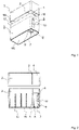
- figure 1 shows an ampoule breaker 5, which is integrated into an ampoule container 3, in which glass ampoules can be accommodated and stored.
- the ampoule breaker 5 is accessible for the ampoule tip from the bottom 15 of the ampoule container 3 .
- the window 10 serves to visually check the position of the ampoule tip in the ampoule crusher 5 and allows the broken ampoule tip to be pushed out again with your finger if it gets stuck in the ampoule crusher 5 .
- the flanks 8 help to position the tip of the ampoule in the ampoule breaker 5, so that a breaking edge 7 formed on the flanks 8 comes to rest on a predetermined breaking point of the ampoule.
- the ampoule container 3 is assigned a cover 1 which has a latching element 16 as a closure element which interacts with a counter-latching element 17 of the ampoule container 3 .
- a storage compartment 4 is provided in the cover 1 and is sealed off from the rest of the interior of the cover 1 by a first bulkhead 2 .
- this receiving compartment 4 comes to rest above the ampoule crusher 5 .
- the device is closed, it is used to transfer a broken ampoule tip into the receiving compartment 4 with a tilting movement of the device from the ampoule breaker 5 into the cover 1 .
- the first bulkhead 2 does not reach into the latching element 16 of the lid 1 so that the device can be closed by the lid 1 latching with the ampoule container 3 .
- the cover 1 can be stripped off and the ampoule tip can be disposed of contactlessly from the receiving compartment 4.
- the first bulkhead 2 in the cover 1 prevents the broken-off ampoule tip from slipping between the ampoules still held in the ampoule container 3 .
- figure 2 shows a cross-section of the device, with the position of a rail element 14 in the interior of the ampoule container 3 being indicated.
- the rail elements are used to position one in the figure 2 not shown separating element 12, which for positioning the individual in the ampoule container 3 to be recorded ampoules is used.
- the figure 2 a tubular plug-in receptacle 6 of the ampoule breaker 5 for receiving the ampoule tip in the ampoule breaker 5. This opens out laterally into the window 10, through which the position of the ampoule tip in the plug-in receptacle 6 can be checked on the one hand and on the other hand with a finger in either direction can be pushed out of the socket 6 or in the direction of the cover 1 in this.
- a second bulkhead 9 is provided, which is arranged in the ampoule container 3 in such a way that it is aligned with the first bulkhead 2 when the lid 1 is opened in the intended manner located on the ampoule container 3.
- the bulkheads 2 and 9 do not have to be continuous or complement each other to form a continuous wall. It is sufficient here if the broken-off ampoule tip is prevented from falling out of the receiving compartment 4 .
- FIG. 3 shows the view of the interior of the ampoule container 3 from above.
- the interior of the ampoule container 3 contains, on the one hand, the ampoule crusher 5 and, on the other hand, a separating element 12 with elastic clamping elements 13 is positioned in the rail elements 14 .
- This separating element 12 divides the interior of the ampoule container 3 into ampoule compartments 11.
- the clamping elements 13 protrude into the ampoule compartments 11 and are thus able to hold ampoules inserted into the ampoule compartments 11 in position.
- the elastic clamping elements are pushed aside while the ampoules are being inserted and build up a pretension which presses the respective ampule against the opposite wall due to the resulting spring force. The resulting static friction prevents the ampoules from falling out.
- the separating element 12 with the clamping elements 13 can be inserted by simply sliding it into the rail elements 14 and removed in the opposite direction, so that the ampoule container 13 can be removed when the separating element 12 can be easily cleaned. It is also readily possible to replace the separating element 12 with a spare part.
- a device in which an ampoule crusher is integrated into an ampoule container is thus described above.
- the lid of the ampoule container has a receptacle for the temporary storage and disposal of a severed ampoule tip.
Landscapes
- Engineering & Computer Science (AREA)
- Mechanical Engineering (AREA)
- Devices For Opening Bottles Or Cans (AREA)
Priority Applications (1)
| Application Number | Priority Date | Filing Date | Title |
|---|---|---|---|
| EP21159306.6A EP4049965A1 (fr) | 2021-02-25 | 2021-02-25 | Récipient à ampoules avec dispositif d'ouvertures d'ampoules intégré |
Applications Claiming Priority (1)
| Application Number | Priority Date | Filing Date | Title |
|---|---|---|---|
| EP21159306.6A EP4049965A1 (fr) | 2021-02-25 | 2021-02-25 | Récipient à ampoules avec dispositif d'ouvertures d'ampoules intégré |
Publications (1)
| Publication Number | Publication Date |
|---|---|
| EP4049965A1 true EP4049965A1 (fr) | 2022-08-31 |
Family
ID=74758655
Family Applications (1)
| Application Number | Title | Priority Date | Filing Date |
|---|---|---|---|
| EP21159306.6A Pending EP4049965A1 (fr) | 2021-02-25 | 2021-02-25 | Récipient à ampoules avec dispositif d'ouvertures d'ampoules intégré |
Country Status (1)
| Country | Link |
|---|---|
| EP (1) | EP4049965A1 (fr) |
Citations (4)
| Publication number | Priority date | Publication date | Assignee | Title |
|---|---|---|---|---|
| DE1920115U (de) * | 1963-11-23 | 1965-07-22 | Hans Klausnitz | Ampullenoeffner. |
| US3640437A (en) * | 1968-12-27 | 1972-02-08 | Merieux Inst | Package for ampoules containing lyophilized products |
| ITMI20081398A1 (it) * | 2008-07-29 | 2010-01-30 | Gpp Ind Grafiche S P A | Scatola per fiale di vetro o simili |
| EP2404864B1 (fr) * | 2010-07-07 | 2017-04-12 | Heraeus Medical GmbH | Brise-ampoule |
-
2021
- 2021-02-25 EP EP21159306.6A patent/EP4049965A1/fr active Pending
Patent Citations (4)
| Publication number | Priority date | Publication date | Assignee | Title |
|---|---|---|---|---|
| DE1920115U (de) * | 1963-11-23 | 1965-07-22 | Hans Klausnitz | Ampullenoeffner. |
| US3640437A (en) * | 1968-12-27 | 1972-02-08 | Merieux Inst | Package for ampoules containing lyophilized products |
| ITMI20081398A1 (it) * | 2008-07-29 | 2010-01-30 | Gpp Ind Grafiche S P A | Scatola per fiale di vetro o simili |
| EP2404864B1 (fr) * | 2010-07-07 | 2017-04-12 | Heraeus Medical GmbH | Brise-ampoule |
Similar Documents
| Publication | Publication Date | Title |
|---|---|---|
| DE102012013927B4 (de) | Verpackungsschachtel mit einer Vielzahl von Einzel-Schachteln | |
| DE2027006C3 (de) | Verpackung für chirurgische Instrumente | |
| EP0105455A1 (fr) | Récipient pour stocker une pile d'images | |
| EP0476343A2 (fr) | Boîte pour jeux de tournevis | |
| DE2813040B2 (de) | Behälter für Kapseln oder Ampullen | |
| EP0105456A2 (fr) | Réceptacle pour une pile de photographies | |
| DE2113434B2 (de) | Behaelter zur aufnahme und einzelnen ausgabe von schreibstiftminen | |
| DE602004005226T2 (de) | Tablettenspender | |
| DE3342489C2 (de) | Vorrichtung zur tiefkalten Lagerung von biologischen oder pharmazeutischen Proben | |
| DE202016100466U1 (de) | Elektrische Anschlussvorrichtung | |
| DE3735301A1 (de) | Pillenteiler | |
| EP3501756A1 (fr) | Fermeture pour un coffre | |
| EP3385182B1 (fr) | Emballage pour un produit à emballer | |
| EP4049965A1 (fr) | Récipient à ampoules avec dispositif d'ouvertures d'ampoules intégré | |
| EP0083563A1 (fr) | Tiroir pour le rangement ordonné de petites pièces | |
| DE1766996C3 (de) | Haltevorrichtung für kleine, mit Zylinderflächen versehene Gegenstände, insbesondere zahnärztliche Bohrer | |
| DE29809737U1 (de) | Sanitätskoffer | |
| DE10230519A1 (de) | Transportbehälter für zylindrische pharmazeutische Behältnisse wie Vials, Ampullen oder ähnliche | |
| DE3046226C2 (de) | Verkaufsständer für Schreib-, Zeichen- oder Malgeräte | |
| EP0457056B1 (fr) | Capuchon de protection de la partie oculaire d'un miroir d'angle dans un véhicule de combat | |
| DE1115638B (de) | Dose fuer Tabletten, Dragees od. dgl. | |
| DE20311478U1 (de) | Vorrichtung zum stoffschlüssigen Verbinden einer Kunststofffolie mit einem kastenförmigen Transportbehälter aus Kunststoff | |
| EP2987516B1 (fr) | Magasin pour au moins une aiguille d'injection sous-cutanee | |
| DE3737049C2 (de) | Funkgerät, insbesondere Funktelefon | |
| DE29705732U1 (de) | Behälter zur Aufbewahrung und selektiven Ausgabe von Gegenständen |
Legal Events
| Date | Code | Title | Description |
|---|---|---|---|
| PUAI | Public reference made under article 153(3) epc to a published international application that has entered the european phase |
Free format text: ORIGINAL CODE: 0009012 |
|
| STAA | Information on the status of an ep patent application or granted ep patent |
Free format text: STATUS: REQUEST FOR EXAMINATION WAS MADE |
|
| 17P | Request for examination filed |
Effective date: 20220209 |
|
| AK | Designated contracting states |
Kind code of ref document: A1 Designated state(s): AL AT BE BG CH CY CZ DE DK EE ES FI FR GB GR HR HU IE IS IT LI LT LU LV MC MK MT NL NO PL PT RO RS SE SI SK SM TR |