EP4050141A1 - Kettfadeneinsatz und gewirkte kettenstruktur für gestricktes netz und damit ausgerüstete ballennetzumwickung - Google Patents
Kettfadeneinsatz und gewirkte kettenstruktur für gestricktes netz und damit ausgerüstete ballennetzumwickung Download PDFInfo
- Publication number
- EP4050141A1 EP4050141A1 EP20914088.8A EP20914088A EP4050141A1 EP 4050141 A1 EP4050141 A1 EP 4050141A1 EP 20914088 A EP20914088 A EP 20914088A EP 4050141 A1 EP4050141 A1 EP 4050141A1
- Authority
- EP
- European Patent Office
- Prior art keywords
- warp
- chain
- knitted
- net
- denier
- Prior art date
- Legal status (The legal status is an assumption and is not a legal conclusion. Google has not performed a legal analysis and makes no representation as to the accuracy of the status listed.)
- Granted
Links
Images


Classifications
-
- D—TEXTILES; PAPER
- D04—BRAIDING; LACE-MAKING; KNITTING; TRIMMINGS; NON-WOVEN FABRICS
- D04B—KNITTING
- D04B21/00—Warp knitting processes for the production of fabrics or articles not dependent on the use of particular machines; Fabrics or articles defined by such processes
- D04B21/10—Open-work fabrics
-
- A—HUMAN NECESSITIES
- A01—AGRICULTURE; FORESTRY; ANIMAL HUSBANDRY; HUNTING; TRAPPING; FISHING
- A01F—PROCESSING OF HARVESTED PRODUCE; HAY OR STRAW PRESSES; DEVICES FOR STORING AGRICULTURAL OR HORTICULTURAL PRODUCE
- A01F1/00—Stationary apparatus or hand tools for forming or binding straw, hay or the like into bundles
- A01F1/04—Fastening or tying devices
-
- A—HUMAN NECESSITIES
- A01—AGRICULTURE; FORESTRY; ANIMAL HUSBANDRY; HUNTING; TRAPPING; FISHING
- A01F—PROCESSING OF HARVESTED PRODUCE; HAY OR STRAW PRESSES; DEVICES FOR STORING AGRICULTURAL OR HORTICULTURAL PRODUCE
- A01F15/00—Baling presses for straw, hay or the like
- A01F15/07—Rotobalers, i.e. machines for forming cylindrical bales by winding and pressing
- A01F15/071—Wrapping devices
- A01F15/0715—Wrapping the bale in the press chamber before opening said chamber
-
- D—TEXTILES; PAPER
- D04—BRAIDING; LACE-MAKING; KNITTING; TRIMMINGS; NON-WOVEN FABRICS
- D04B—KNITTING
- D04B21/00—Warp knitting processes for the production of fabrics or articles not dependent on the use of particular machines; Fabrics or articles defined by such processes
- D04B21/06—Patterned fabrics or articles
-
- A—HUMAN NECESSITIES
- A01—AGRICULTURE; FORESTRY; ANIMAL HUSBANDRY; HUNTING; TRAPPING; FISHING
- A01F—PROCESSING OF HARVESTED PRODUCE; HAY OR STRAW PRESSES; DEVICES FOR STORING AGRICULTURAL OR HORTICULTURAL PRODUCE
- A01F15/00—Baling presses for straw, hay or the like
- A01F15/07—Rotobalers, i.e. machines for forming cylindrical bales by winding and pressing
- A01F15/071—Wrapping devices
- A01F2015/0745—Special features of the wrapping material for wrapping the bale
-
- D—TEXTILES; PAPER
- D10—INDEXING SCHEME ASSOCIATED WITH SUBLASSES OF SECTION D, RELATING TO TEXTILES
- D10B—INDEXING SCHEME ASSOCIATED WITH SUBLASSES OF SECTION D, RELATING TO TEXTILES
- D10B2403/00—Details of fabric structure established in the fabric forming process
- D10B2403/02—Cross-sectional features
- D10B2403/024—Fabric incorporating additional compounds
- D10B2403/0241—Fabric incorporating additional compounds enhancing mechanical properties
- D10B2403/02411—Fabric incorporating additional compounds enhancing mechanical properties with a single array of unbent yarn, e.g. unidirectional reinforcement fabrics
-
- D—TEXTILES; PAPER
- D10—INDEXING SCHEME ASSOCIATED WITH SUBLASSES OF SECTION D, RELATING TO TEXTILES
- D10B—INDEXING SCHEME ASSOCIATED WITH SUBLASSES OF SECTION D, RELATING TO TEXTILES
- D10B2505/00—Industrial
- D10B2505/10—Packaging, e.g. bags
-
- D—TEXTILES; PAPER
- D10—INDEXING SCHEME ASSOCIATED WITH SUBLASSES OF SECTION D, RELATING TO TEXTILES
- D10B—INDEXING SCHEME ASSOCIATED WITH SUBLASSES OF SECTION D, RELATING TO TEXTILES
- D10B2507/00—Sport; Military
- D10B2507/02—Nets
Definitions
- the present invention relates to a knitted net structure, in particular to a warp insertion and warp chain knitted chain structure for knitted net, and a bale net wrap using the same.
- the bale net wrap is mainly used for bundling and packaging forage, straw and the like.
- the bale net wrap is a kind of knotless net, which is named for bundling straw and forage, and may also be referred to as a wrapping net. It is knitted by a warp knitting machine with high production efficiency.
- the bale net is characterized by large mesh, and has the functional requirement of a certain bearing strength.
- the specific structure of the existing baling net includes a plurality of warp chains 1 parallel along a warp direction.
- Each warp chain 1 consists of a plurality of groups of warp-knitted loop links 2 connected in series. Insertion wefts 3 are provided between two adjacent warp chains 1 along a weft direction to form a net structure. Because of the warp-knitted structure, there are looping structures between the loop links 2 in each warp chain 1 and between the insertion weft 3 and the loop link 2. Therefore, there is no knot in the whole net structure, forming a knotless mesh.
- the bundling function of the baling net it is required to have a certain strength along the wrap direction.
- the existing baling net and the baling nets involved in patents CN202131464U , CN206512385U and CN206376082U the external force after bundling straw, forage and the like is mainly born by the warp chains 1. Therefore, in order to enhance the bearing capacity of the baling net, the bearing capacity of the warp chains 1 should be increased as much as possible.
- each warp chain 1 it is formed by looping a bundle of looping fibers 4.
- the bundle of looping fibers 4 may be a single filament or formed by arranging and combining a plurality of filaments in parallel.
- loop links 2 the structure in the dashed box in FIG. 1
- the looping fibers 4 after looping are bent (as shown in FIG. 1 ), so that the strength is lower than that of the original plain and straight fiber.
- the fineness (denier) of each warp chain 1 is three times that of the bundle of looping fibers 4, but its strength is three times less than that of the bundle of looping fibers 4.
- each wrap chain 1 In order to improve the bearing capacity of each wrap chain 1, two methods may be adopted. One is to improve the strength of each bundle of looping fibers 4. The other is to improve the toughness of looping fibers 4 and reduce the weakening of the strength of looping fibers 4 caused by bending into loops during warp knitting. In the prior art, the improvement of fiber strength has a certain technical bottleneck, and the weakening of fiber strength caused by looping during warp knitting cannot be avoided.
- knitted net yarns are warp-knitted to form net body wefts and net body warps. It further includes knitting insertion yarns, the direction of the knitting insertion yarns is the same as that of the net body wefts and/or net body warps, and the length of the net body warps and/or net body wefts is less than or equal to the length of the corresponding knitting insertion yarns.
- the purpose of providing the knitting insertion yarns is to use the knitting insertion yarns to adapt to the size of the bale after the net body is broken, so as to effectively realize the function of wrapping the bale again.
- the bale is prevented from scattering after the wefts and warps are broken.
- the insertion yarns need to be used to prevent the bale from scattering, which requires that the strength of the insertion yarns is higher than that of the wefts or warps, that is, insertion yarns with higher strength need to be used, so that it will inevitably and greatly increases the weight and production cost of the baling net. Obviously, it cannot solve the problem of weakened fiber strength caused by looping during warp knitting.
- the present invention is directed to provide a warp-inserted warp chain knitted chain structure for a knitted net and a baling net using the same.
- the warp chain knitted chain structure is formed by combining two parts, i.e., a warp-knitted chain and an insertion warp plainly and straightly inserted into the warp-knitted chain, the warp-knitted chain is formed by serially connecting loop links formed through warp knitting of looping fibers, and the ratio of the denier A of the looping fibers to the denier C of the insertion warp is less than or equal to 2.33.
- the plain and straight insertion warp and the warp-knitted chain are used to jointly bear the load born by the warp chain, the insertion warp fibers do not have the problems of bending and weakened strength, and the strength of the knitted chain is improved, thus improving the overall strength of the baling net with the warp-inserted warp chain knitted chain structure.
- the warp-inserted warp chain knitted chain structure for the knitted net provided by the present invention is formed by combining two parts, i.e., a warp-knitted chain and an insertion warp plainly and straightly inserted into the warp-knitted chain, the warp-knitted chain is formed by serially connecting loop links formed through warp knitting of looping fibers, the denier of the warp-knitted chain is 3 times the denier A of the looping fibers, and the ratio of the denier A of the looping fibers to the denier C of the insertion warp is less than or equal to 2.33.
- the denier A of the looping fibers is not more than 0.2917B
- the denier C of the insertion warp is not less than 0.125B.
- the total denier of fibers of the warp-inserted warp chain knitted chain structure is 1200D
- the denier A of the looping fibers (4) is not more than 350D
- the denier C of the insertion warp (5) is not less than 150D.
- the insertion warp is a single fiber filament or is formed by combining two or more sub-insertion warp fiber filaments
- the looping fiber is a single fiber filament or is formed by combining two or more fiber filaments.
- the insertion warp is alternately threaded up and down in the loop links in the warp-knitted chain.
- connecting knots spaced along a length direction of warp chains are further provided between the warp-knitted chain and the insertion warp.
- connecting knots are connecting loops formed through warp knitting between the insertion warp and the loop links of the warp-knitted chain.
- one connecting knot is provided in the warp-knitted chain at an interval of at least one loop link.
- a baling net provided by the present invention includes a plurality of parallel warp chains and insertion wefts provided between two adjacent warp chains. All or part of the warp chains of the baling net have the warp-inserted warp chain knitted chain structure for knitted net.
- the insertion wefts are wavily connected to the loop links of two adjacent warp chains.
- the present invention provides a warp-inserted warp chain knitted chain structure for knitted net, aiming at solving the technical problem of reducing the weakening of the fiber strength caused by looping during warp knitting, and constructing a baling net with a novel knitted chain structure.
- the warp-inserted warp chain knitted chain structure is formed by combining two parts, i.e., a warp-knitted chain L and an insertion warp 5 plainly and straightly inserted into the warp-knitted chain L.
- the warp-knitted chain L is formed by serially connecting loop links 2 formed through warp knitting of looping fibers 4.
- the denier of the warp-knitted chain L is 3 times the denier A of the looping fibers 4.
- the ratio of the denier A of the looping fibers 4 to the denier C of the insertion warp 5 is less than or equal to 2.33.
- the warp-knitted chain L is formed by serially connecting open or closed loop links 2 formed through warp knitting of looping fibers 4;
- the insertion warp 5 may be a single fiber filament or may be formed by combining two or more sub-insertion warp fiber filaments; and
- the looping fiber 4 may be a single fiber filament or may be formed by combining two or more fiber filaments.
- the plain and straight insertion warp and the warp-knitted chain are used to jointly bear the load born by the warp chain, the insertion warp does not have the problems of bending and weakened strength, and the strength of the knitted chain is improved, thus improving the overall strength of the baling net with the warp-inserted warp chain knitted chain structure.
- the warp chain 1 in FIG. 1 is redesigned into the warp chain 1 in FIG. 2 .
- the fibers of the redesigned warp chain 1 consist of two parts. One part is referred to as looping fibers 4 for forming loops 2, and the other part is referred to as insertion warp fibers, insertion warp 5 for short, and are not looped but are inserted into loop links 2 formed by the looping fibers 4.
- the insertion warp fibers inserted into the loop links 2 are in a plain and straight state and are not bent, so that the strength of the insertion warp fibers in the warp chain 1 will not be weakened.
- the warp chain 1 in the present invention still has looping fibers 4.
- the insertion warp 5 is added to form the warp chain 1.
- m is a positive integer more than or equal to 1.
- the looping fiber 4 consists of n fibers.
- the denier of the fibers are A1, A2,... A n respectively.
- n is a positive integer.
- the sum of A1, A2,... A n is A, which is not more than 0.2917B.
- the insertion warp 5 consists of m sub-insertion warp fiber filaments.
- the finenesses (denier) of the sub-insertion warp fibers are C1, C2,... C m respectively.
- m is a positive integer.
- the sum of C1, C2,... Cm is C, which is not less than 0.125B.
- the finer looping fibers 4 realize the structure of the warp-knitted chain L in the single warp chain 1. That is, fewer fibers need to be bent, and thus the strength of fewer fibers is weakened; and more fibers are used as the insertion warps 5, thus maximizing the total strength of the warp chains 1.
- the total denier of fibers of a single warp chain 1 is 1200D (D is the unit of fiber fineness: denier).
- the denier A of the looping fiber 4 is not more than 350D
- the total denier C of the insertion warp 5 is not less than 150D
- the ratio of the denier of the looping fiber and the denier of the insertion warp fiber is especially suitable for the baling net, which takes into account the performance and cost-effectiveness of the baling net.
- A/C ratio less than or equal to 2.33 is a balance point between performance and price in the actual production process.
- A/C ratio becomes smaller and smaller, the economic benefit becomes greater and greater. Therefore, A/C less than or equal to 2.33 is a key technical point in the present invention.
- connecting knots 6 spaced along a length direction of warp chains are further provided between the warp-knitted chain L and the insertion warp 5.
- the use of the connecting knots 6 avoids the relative movement between the insertion warp 5 and the loop links 2 in the warp direction, and improves the stability of the warp chain knitted chain and the baling net.
- the connecting knots 6 are connecting loops formed between the insertion warp 5 and the loop links 2 of the warp-knitted chain L by adopting a warp knitting method.
- One connecting knot 6 is provided in the warp-knitted chain L at an interval of at least one loop link 2.
- the more times the insertion warp 5 is bent and knotted the greater the material consumption of the insertion warp 5 and the worse the economic benefit.
- the connection stability between the warp chain 1 and the insertion warp 5 is worse.
- the fewer times the insertion warp 5 is bent and knotted the smaller the material consumption of the insertion warp 5 and the better the economic benefit.
- the plain and straight insertion warp 5 and the warp-knitted chain L jointly bear the load born by the warp chain 1.
- the "plain and straight" of the insertion warp 5 is relative to the bent knitted chain structure of the looping fibers 4.
- Appropriate bending formed by that the insertion structure of the insertion warp 5 in a direction perpendicular to the knitted net surface makes the insertion warp 5 alternately threaded up and down in the loop links 2 in the vertical direction also belongs to the scope of the meaning of "plain and straight" in the present invention.
- the warp-inserted warp chain knitted chain structure for the knitted net provided by the present invention can be used for the knitted net with a common open or closed loop knitted chain structure. In the present invention, it is particularly applicable to the existing baling net shown in FIG. 1 .
- the present invention further relates to a baling net with a novel knitted chain structure.
- the baling net includes a plurality of parallel warp chains 1 and insertion wefts 3 provided between every two warp chains 1. All or part of the warp chains 1 of the baling net have the warp-inserted warp chain knitted chain structure for the knitted net.
- the structure of the insertion wefts 3 is the same as that of the existing baling net.
- the insertion wefts 3 are wavily connected to the loop links 2 of two adjacent warp chains 1.
- Each warp chain 1 of the baling net can adopt the warp-inserted warp chain knitted chain structure for the knitted net, or the warp-inserted warp chain knitted chain structure for the knitted net can be adopted in the spaced warp chains 1 as required.
- the specific application is flexible according to the design needs. The present invention will be further described below in combination with the examples.
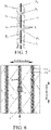
- FIG. 4 illustrates a partial structural diagram of a baling net with one insertion warp 5 in each warp chain 1.
- Reference numeral 1 represents the warp chain
- reference numeral 2 represents a loop link
- reference numeral 3 represents an insertion weft
- reference numeral 4 represents a looping fiber
- reference numeral 5 represents the insertion warp
- reference numeral L represents a warp-knitted chain.
- the warp chain 1 is characterized in that it consists of two parts. One part is the warp-knitted chain L formed by serially connecting the loop links 2 (one loop link is shown in the dashed box in FIG. 4 ), and the other part is the insertion warp 5 inserted into the warp-knitted chain L.
- the structure of the warp-knitted chain L consists of common warp-knitted open or closed loops.
- one insertion warp 5 is continuously threaded in the warp-knitted chain L. Drawing the insertion warp 5 along the warp direction can realize movement relative to the warp-knitted chain L.
- the movement range of the insertion warps 5 in the weft direction does not exceed the area of the loop links 2.
- the vertical direction For the position relationship between the insertion warp 5 and the direction perpendicular to the surface of the baling net (hereinafter referred to as the vertical direction), four loop links X 1 , X 2 , X 3 and X 4 on one warp chain 1 are intercepted from FIG. 4 , and the cross-over points with the insertion warp 5 are P 1 , P 2 , P 3 and P 4 respectively, as shown in FIG. 5 .
- the insertion warp 5 At the cross-over point P 1 , the insertion warp 5 is located above the looping fiber 4 of the loop link X 1 .
- the insertion warp 5 is located below the looping fiber 4 of the loop link X 2 .
- the insertion warp 5 is located above the looping fiber 4 of the loop link X 3 .
- the insertion warp 5 is located below the looping fiber 4 of the loop link X 4 . That is, on the whole warp chain 1, the insertion warp 5 and the looping fiber 4 are spaced and respectively alternated up and down, and the insertion warp 5 is limited in the loop link 2 in the vertical direction.
- the insertion warp 5 may also be inserted into the warp-knitted chain L alternately up and down at an interval of a plurality of loop links 2 as required.
- the total denier of fibers of a single warp chain 1 is 1200D
- the denier A of the looping fiber 4 is less than or equal to 350D
- the denier C of the insertion warp 5 is more than or equal to 150D
- the denier of the insertion warp 5 in different warp chains 1 is equal, or the denier of the insertion warp 5 in different warp chains 1 is not equal, and the baling net structure thus formed is a proprietary structure in the present invention.
- FIG. 6 illustrates a partial structural diagram of a baling net with two insertion warps 5 in each warp chain 1.
- Reference numeral 1 represents the warp chain
- reference numeral 2 represents a loop link
- reference numeral 3 represents an insertion weft
- reference numeral 4 represents a looping fiber
- reference numeral 5 represents the insertion warp
- reference numeral 5-1 represents a first sub-insertion warp
- a reference numeral 5-2 represents a second sub-insertion warp
- reference numeral L represents a warp-knitted chain.
- the warp chain 1 also consists of two parts. One part is the warp-knitted chain L formed by serially connecting the loop links 2 (one loop link is shown in the dashed box in FIG. 6 ), and the other part is the insertion warp 5 inserted into the warp-knitted chain L.
- the insertion warp 5 includes the first sub-insertion warp 5-1 and the second sub-insertion warp 5-2.
- the structure of the warp-knitted chain L in this example is exactly the same as that of the warp-knitted chain L in Example 1.
- the insertion warp 5 consists of two fibers, which may also be referred to as sub-insertion warps.
- the first sub-insertion warp 5-1 and the second sub-insertion warp 5-2 replace the insertion warp 5 in Embodiment 1.
- the functions, fixing methods and the like of the first sub-insertion warp 5-1 and the second sub-insertion warp 5-2 are the same as those of the insertion warp 5 in Example 1.
- the total denier of fibers of a single warp chain 1 is 1200D
- the denier of the looping fiber 4 is A
- A is less than or equal to 350D
- the sum of Cl and C2 is more than or equal to 150D, that is, C1+C2 ⁇ 150D
- the denier C1 of the first sub-insertion warp 5-1 is equal to the denier C2 of the second sub-insertion warp 5-2, that is, the two sub-insertion warps are the same in fineness; or the denier C1 of the first sub-insertion warp 5-1 and the denier C2 of the second sub-insertion warp 5-2 are not equal, that is, the two sub-insertion warps are different in fineness.
- the denier C1 of the first sub-insertion warp 5-1 and the denier C2 of the second sub-insertion warp 5-2 are not equal, the denier C1 and the denier C2 may be combined in any way, and the baling net structure thus formed by inserting the sub-insertion warps into the warp-knitted chain L is a proprietary structure of the baling net provided by the present invention.
- the denier of the first sub-insertion warps 5-1 in different warp chains 1 is equal or not equal
- the denier of the second sub-insertion warps 5-2 in different warp chains 1 is equal or not equal
- the baling net structure thus formed is a proprietary structure of the baling net provided by the present invention.
- the insertion warp 5 may consist of two or more sub-insertion warps.
- the insertion warp 5 consists of three sub-insertion warps, that is, the insertion warp 5 consists of a first sub-insertion warp 5-1, a second sub-insertion warp 5-2 and a third sub-insertion warp 5-3. That is, the number m of sub-insertion warps is a positive integer more than or equal to 1.
- the baling net structure thus formed by inserting the sub-insertion warps into the warp-knitted chain L is also a proprietary structure of the baling net provided by the present invention.
- the number m of sub-insertion warps is more than or equal to 3
- the denier of m sub-insertion warps is the same or different
- the baling net structure thus formed by inserting the sub-insertion warps into one warp-knitted chain L is a proprietary structure of the baling net provided by the present invention.
- the baling net structure thus formed is a proprietary structure of the baling net provided by the present invention.
- FIG. 8 illustrates a partial structural diagram of a baling net with one insertion warp 5 in each warp chain 1 and with connecting knots 6 at an interval of a plurality of loop links in a warp direction.
- Reference numeral 1 represents the warp chain
- reference numeral 2 represents a loop link
- reference numeral 3 represents an insertion weft
- reference numeral 4 represents a looping fiber
- reference numeral 5 represents the insertion warp
- reference numeral 6 represents a connecting knot
- reference numeral L represents a warp-knitted chain.
- the warp chain 1 also consists of two parts. One part is the warp-knitted chain L formed by serially connecting the loop links 2 (one loop link is shown in the dashed box in FIG.
- the connecting knots 6 are between the insertion warp 5 and the loop links 2, so that the insertion warp 5 is bound with the loop links 2 at the connecting knots 6 to prevent the relative movement of the insertion warp 5 in the warp-knitted chain L.
- the structure of the warp-knitted chain L is exactly the same as that of the warp-knitted chain L in Example 1 and Example 2.
- the connecting knots 6 are connecting loops formed through warp knitting between the insertion warp 5 and the loop links 2.
- the baling net structure thus formed is a proprietary structure of the baling net provided by the present invention.
- the baling net structure thus formed is a proprietary structure of the baling net provided by the present invention.
- the baling net structure thus formed is a proprietary structure of the baling net provided by the present invention.
- the baling net structure thus formed is a proprietary structure of the baling net provided by the present invention.
- FIG. 11 illustrates a partial structural diagram of a baling net with two insertion warps 5 in each warp chain 1 and with connecting knots 6 at an interval of a plurality of loop links in a warp direction.
- Reference numeral 1 represents the warp chain
- reference numeral 2 represents a loop link
- reference numeral 3 represents an insertion weft
- reference numeral 4 represents a looping fiber
- reference numeral 5 represents the insertion warp
- reference numeral 5-1 represents a first sub-insertion warp
- reference numeral 5-2 represents a second sub-insertion warp
- reference numeral 6 represents a connecting knot
- reference numeral L represents a warp-knitted chain.
- the warp chain 1 also consists of two parts.
- One part is the warp-knitted chain L formed by serially connecting the loop links 2 (one loop link is shown in the dashed box in FIG. 11 ), and the other part is the insertion warp 5 inserted into the warp-knitted chain L.
- the connecting knots 6 are between the first sub-insertion warp 5-1 and the second sub-insertion warp 5-2 and the loop links 2, so that the first sub-insertion warp 5-1 and the second sub-insertion warp 5-2 are bound with the loop links 2 at the connecting knots 6 to prevent the relative movement of the first sub-insertion warp 5-1 and the second sub-insertion warp 5-2 in the warp-knitted chain L.
- the insertion warp 5 consists of the first sub-insertion warp 5-1 and the second sub-insertion warp 5-2.
- the first sub-insertion warp 5-1 and the second sub-insertion warp 5-2 replace the insertion warp 5 in Example 3.
- the functions, fixing methods and the like of the first sub-insertion warp 5-1 and the second sub-insertion warp 5-2 in this example are the same as those of the insertion warp 5 in Example 3.
- the connecting knots 6 are connecting loops formed through warp knitting between the first sub-insertion warp 5-1 and the second sub-insertion warp 5-2 and the loop links 2.
- the baling net structure thus formed is a proprietary structure of the baling net provided by the present invention.
- the baling net structure thus formed is a proprietary structure of the baling net provided by the present invention.
- the baling net structure thus formed is a proprietary structure of the baling net provided by the present invention.
- the connecting knot 6 on one warp chain 1 there is one connecting knot 6 at an interval of more than three loop links 2 on the first sub-insertion warp 5-1 and the second sub-insertion warp 5-2, such as four, five, six..., and the baling net structure thus formed is a proprietary structure of the baling net provided by the present invention.
- the insertion warp 5 in Example 4 may also consist of more than three, four, five... insertion warps in addition to two insertion warps.
- the first sub-insertion warp 5-1, the second sub-insertion warp 5-2 and the third sub-insertion warp 5-3 form the insertion warp 5, and there is one connecting knot 6 at an interval of respectively one loop link 2 (see FIG. 14 ), two loop links 2 (see FIG. 15 ), three loop links 2 (see FIG. 16 ), and a plurality of, such as four, five, six...loop links 2.
- the structures with more than three sub-insertion warps and having an interval of more than three loop links 2 will not be enumerated one by one. All combinations of more than three sub-insertion warps and the interval of more than three loop links 2 still belong to the embodiments of the present invention, and the baling net structures thus formed are proprietary structures of the baling net provided by the present invention.
- the warp-inserted warp chain knitted chain structure is formed by combining two parts, i.e., a warp-knitted chain and an insertion warp plainly and straightly inserted into the warp-knitted chain, the warp-knitted chain is formed by serially connecting loop links formed through warp knitting of looping fibers, the denier of the warp-knitted chain is 3 times the denier A of the looping fibers, and the ratio of the denier A of the looping fibers to the denier C of the insertion warp is less than or equal to 2.33.
- the plain and straight insertion warp and the warp-knitted chain are used to jointly bear the load born by the warp chain, the insertion warp does not have the problems of bending and weakened strength, and the strength of the knitted chain is improved, thus improving the overall strength of the baling net with the warp-inserted warp chain knitted chain structure.
- the overall strength of the knitted chain can be maximized to consider the performance and price of the baling net at the same time by optimizing the ratio of the denier of the looping fibers to the denier of the insertion warp fibers.
- the use of the connecting knots avoids the relative movement between the insertion warp and the loops in the warp direction, and improves the stability of the warp chain knitted chain and the baling net.
Landscapes
- Engineering & Computer Science (AREA)
- Textile Engineering (AREA)
- Life Sciences & Earth Sciences (AREA)
- Environmental Sciences (AREA)
- Knitting Of Fabric (AREA)
- Braiding, Manufacturing Of Bobbin-Net Or Lace, And Manufacturing Of Nets By Knotting (AREA)
Applications Claiming Priority (2)
| Application Number | Priority Date | Filing Date | Title |
|---|---|---|---|
| CN202010029976.7A CN111101283A (zh) | 2020-01-13 | 2020-01-13 | 一种编织网用衬经经向链编链结构及应用其的捆草网 |
| PCT/CN2020/092204 WO2021143002A1 (zh) | 2020-01-13 | 2020-05-26 | 一种编织网用衬经经向链编链结构及应用其的捆草网 |
Publications (4)
| Publication Number | Publication Date |
|---|---|
| EP4050141A1 true EP4050141A1 (de) | 2022-08-31 |
| EP4050141A4 EP4050141A4 (de) | 2022-12-21 |
| EP4050141C0 EP4050141C0 (de) | 2025-01-01 |
| EP4050141B1 EP4050141B1 (de) | 2025-01-01 |
Family
ID=70426069
Family Applications (1)
| Application Number | Title | Priority Date | Filing Date |
|---|---|---|---|
| EP20914088.8A Active EP4050141B1 (de) | 2020-01-13 | 2020-05-26 | Gewirkte kettmaschenstruktur mit kettfadeneinlage für ein gewirktes verpackungsnetz, und damit ausgerüstetes ballennetz |
Country Status (5)
| Country | Link |
|---|---|
| US (1) | US20230002942A1 (de) |
| EP (1) | EP4050141B1 (de) |
| CN (1) | CN111101283A (de) |
| AU (1) | AU2020423394B2 (de) |
| WO (1) | WO2021143002A1 (de) |
Families Citing this family (6)
| Publication number | Priority date | Publication date | Assignee | Title |
|---|---|---|---|---|
| CN111101283A (zh) * | 2020-01-13 | 2020-05-05 | 常州市鑫辉网具有限公司 | 一种编织网用衬经经向链编链结构及应用其的捆草网 |
| JP7306526B1 (ja) * | 2022-04-08 | 2023-07-11 | カール マイヤー ストール アールアンドディー ゲーエムベーハー | 経編地の編成方法及び経編機 |
| CN115474482B (zh) * | 2022-08-30 | 2023-08-01 | 常州市鑫辉网具有限公司 | 一种编织网 |
| JP2025187868A (ja) * | 2024-06-14 | 2025-12-25 | 株式会社アシックス | 繊維構造体および繊維構造体の製造方法 |
| CN118600632B (zh) * | 2024-06-18 | 2025-12-12 | 华峰化学股份有限公司 | 一种单层弹性材料及其应用 |
| CN119433803B (zh) * | 2024-12-06 | 2026-02-10 | 常州市鑫辉网具有限公司 | 一种非编织捆缚网及网卷 |
Family Cites Families (24)
| Publication number | Priority date | Publication date | Assignee | Title |
|---|---|---|---|---|
| US2691286A (en) * | 1953-08-31 | 1954-10-12 | Gilbert N Cooper | Warp-knitted fabric |
| CS184152B1 (en) * | 1976-03-16 | 1978-08-31 | Ervin Faulhaber | Knitted or knit-bonded fabric and apparatus for manufacturing the same |
| DD217553B3 (de) * | 1983-02-28 | 1992-12-24 | Malimo Maschinenbau Gmbh Chemn | Verfahren und vorrichtung zum herstellen einer textilbahn |
| US4841749A (en) * | 1985-10-04 | 1989-06-27 | Burlington Industries, Inc. | Warp-knit, weft-inserted fabric with multiple substrate layers and method of producing same |
| DE3672982D1 (de) * | 1985-12-05 | 1990-08-30 | Sakae Lace Kk | Kettengewirkte spitzen. |
| US5104714A (en) * | 1989-11-30 | 1992-04-14 | Tama Plastic Industry | Elastic plastic netting made of oriented strands |
| DE69120803D1 (de) * | 1991-04-30 | 1996-08-14 | Cintel S A S Di Fontana Paola | Elastisches Abstützelement oder Riemen zum Wattieren für Möbelstücke oder Wagensessel |
| CN1046560C (zh) * | 1994-04-21 | 1999-11-17 | 发事达株式会社 | 一种由链式纱和衬垫纱构成的复合纱 |
| US5795835A (en) * | 1995-08-28 | 1998-08-18 | The Tensar Corporation | Bonded composite knitted structural textiles |
| GB2390856A (en) * | 2002-07-16 | 2004-01-21 | Alcare Co Ltd | Warp-knit stretch fabric for medical use |
| JP2004353104A (ja) * | 2003-05-27 | 2004-12-16 | Kci Warp Knit Kk | 編物 |
| ES2617277T3 (es) * | 2011-05-20 | 2017-06-16 | Tama Plastic Industry | Red con indicador de alargamiento y procedimiento para determinar el alargamiento de una red |
| CN202131464U (zh) | 2011-06-29 | 2012-02-01 | 瑞安市嘉诚塑业有限公司 | 捆草网 |
| KR101154902B1 (ko) * | 2011-12-28 | 2012-06-13 | 김진숙 | 포장 결속용 망원단 |
| KR101459111B1 (ko) * | 2014-01-15 | 2014-11-13 | 김진숙 | 올풀림 방지나 좌우 전폭 유지가 가능한 망원단 및 포장결속용 망원단 |
| CN205295657U (zh) | 2015-11-18 | 2016-06-08 | 浙江长兴易佳网业有限公司 | 一种捆草网 |
| DE102016125601A1 (de) * | 2016-12-23 | 2018-06-28 | Karatzis S.A. Industrial & Hotelier Enterprises | Netz mit Unterstützungsfaden |
| CN206512385U (zh) | 2017-01-12 | 2017-09-22 | 周巨德 | 一种稳固型捆草网 |
| CN206376082U (zh) | 2017-01-12 | 2017-08-04 | 衡水华洋纺织新材料有限公司 | 捆草网 |
| CN106995975A (zh) * | 2017-05-18 | 2017-08-01 | 江苏理工学院 | 一种新型经编绝缘材料、该材料的制备方法及应用 |
| CN209537756U (zh) * | 2019-02-13 | 2019-10-25 | 广州市天海花边有限公司 | 一种轻薄强弹面料的花边组织结构 |
| CN110318153B (zh) * | 2019-08-08 | 2024-03-22 | 常州市鑫辉网具有限公司 | 一种编织捆草网经编机 |
| CN211645570U (zh) * | 2020-01-13 | 2020-10-09 | 常州市鑫辉网具有限公司 | 一种编织网用衬经经向链编链结构及应用其的捆草网 |
| CN111101283A (zh) * | 2020-01-13 | 2020-05-05 | 常州市鑫辉网具有限公司 | 一种编织网用衬经经向链编链结构及应用其的捆草网 |
-
2020
- 2020-01-13 CN CN202010029976.7A patent/CN111101283A/zh active Pending
- 2020-05-26 WO PCT/CN2020/092204 patent/WO2021143002A1/zh not_active Ceased
- 2020-05-26 AU AU2020423394A patent/AU2020423394B2/en active Active
- 2020-05-26 US US17/780,438 patent/US20230002942A1/en not_active Abandoned
- 2020-05-26 EP EP20914088.8A patent/EP4050141B1/de active Active
Also Published As
| Publication number | Publication date |
|---|---|
| WO2021143002A1 (zh) | 2021-07-22 |
| US20230002942A1 (en) | 2023-01-05 |
| CN111101283A (zh) | 2020-05-05 |
| EP4050141C0 (de) | 2025-01-01 |
| AU2020423394B2 (en) | 2024-01-04 |
| EP4050141B1 (de) | 2025-01-01 |
| EP4050141A4 (de) | 2022-12-21 |
| AU2020423394A1 (en) | 2022-07-14 |
Similar Documents
| Publication | Publication Date | Title |
|---|---|---|
| EP4050141B1 (de) | Gewirkte kettmaschenstruktur mit kettfadeneinlage für ein gewirktes verpackungsnetz, und damit ausgerüstetes ballennetz | |
| US10100462B2 (en) | Synthetic-fiber rope | |
| JP2013139295A (ja) | 包装結束用網生地 | |
| CN115474482B (zh) | 一种编织网 | |
| CN211645570U (zh) | 一种编织网用衬经经向链编链结构及应用其的捆草网 | |
| US2996905A (en) | Net without knots | |
| US20080277952A1 (en) | Textile sling combining multiple types of fibers and method of manufacturing same | |
| US4785613A (en) | Grasscatcher bag fabric | |
| KR102326563B1 (ko) | 농산물 저장 톤백 제작용 직물 및 그 톤백 | |
| CN202626543U (zh) | 一种直线编织的绞捻无结网 | |
| CN201358453Y (zh) | 一种高强经编土工格栅 | |
| JP2934527B2 (ja) | 土木・建築用メッシュシート | |
| KR102501926B1 (ko) | 굴을 채취 및 보관하기 위한 그물 | |
| CN220079346U (zh) | 针织面料 | |
| US20060185400A1 (en) | Mesh bag | |
| RU2133789C1 (ru) | Основовязаный филейный трикотаж | |
| CN220132487U (zh) | 弹力针织布 | |
| CN220952355U (zh) | 柔软弹性针织布 | |
| CN220887880U (zh) | 一种防脱散织带 | |
| CN221778067U (zh) | 针织网眼面料 | |
| CN219637460U (zh) | 透气针织坯布 | |
| CN222182687U (zh) | 针织面料 | |
| CN219930412U (zh) | 弹力面料 | |
| JP4824488B2 (ja) | メッシュシート | |
| CN2910977Y (zh) | 输送带防撕裂网 |
Legal Events
| Date | Code | Title | Description |
|---|---|---|---|
| STAA | Information on the status of an ep patent application or granted ep patent |
Free format text: STATUS: THE INTERNATIONAL PUBLICATION HAS BEEN MADE |
|
| PUAI | Public reference made under article 153(3) epc to a published international application that has entered the european phase |
Free format text: ORIGINAL CODE: 0009012 |
|
| STAA | Information on the status of an ep patent application or granted ep patent |
Free format text: STATUS: REQUEST FOR EXAMINATION WAS MADE |
|
| 17P | Request for examination filed |
Effective date: 20220525 |
|
| AK | Designated contracting states |
Kind code of ref document: A1 Designated state(s): AL AT BE BG CH CY CZ DE DK EE ES FI FR GB GR HR HU IE IS IT LI LT LU LV MC MK MT NL NO PL PT RO RS SE SI SK SM TR |
|
| REG | Reference to a national code |
Ref country code: DE Ref legal event code: R079 Free format text: PREVIOUS MAIN CLASS: D04B0021060000 Ipc: D04B0021100000 Ref document number: 602020044328 Country of ref document: DE |
|
| A4 | Supplementary search report drawn up and despatched |
Effective date: 20221121 |
|
| RIC1 | Information provided on ipc code assigned before grant |
Ipc: A41F 1/04 20060101ALN20221115BHEP Ipc: D04B 21/10 20060101AFI20221115BHEP |
|
| DAV | Request for validation of the european patent (deleted) | ||
| DAX | Request for extension of the european patent (deleted) | ||
| GRAP | Despatch of communication of intention to grant a patent |
Free format text: ORIGINAL CODE: EPIDOSNIGR1 |
|
| STAA | Information on the status of an ep patent application or granted ep patent |
Free format text: STATUS: GRANT OF PATENT IS INTENDED |
|
| RIC1 | Information provided on ipc code assigned before grant |
Ipc: A41F 1/04 20060101ALN20240703BHEP Ipc: D04B 21/10 20060101AFI20240703BHEP |
|
| INTG | Intention to grant announced |
Effective date: 20240725 |
|
| GRAS | Grant fee paid |
Free format text: ORIGINAL CODE: EPIDOSNIGR3 |
|
| GRAA | (expected) grant |
Free format text: ORIGINAL CODE: 0009210 |
|
| STAA | Information on the status of an ep patent application or granted ep patent |
Free format text: STATUS: THE PATENT HAS BEEN GRANTED |
|
| AK | Designated contracting states |
Kind code of ref document: B1 Designated state(s): AL AT BE BG CH CY CZ DE DK EE ES FI FR GB GR HR HU IE IS IT LI LT LU LV MC MK MT NL NO PL PT RO RS SE SI SK SM TR |
|
| REG | Reference to a national code |
Ref country code: GB Ref legal event code: FG4D |
|
| REG | Reference to a national code |
Ref country code: CH Ref legal event code: EP |
|
| REG | Reference to a national code |
Ref country code: DE Ref legal event code: R096 Ref document number: 602020044328 Country of ref document: DE |
|
| REG | Reference to a national code |
Ref country code: IE Ref legal event code: FG4D |
|
| U01 | Request for unitary effect filed |
Effective date: 20250116 |
|
| U07 | Unitary effect registered |
Designated state(s): AT BE BG DE DK EE FI FR IT LT LU LV MT NL PT RO SE SI Effective date: 20250123 |
|
| U20 | Renewal fee for the european patent with unitary effect paid |
Year of fee payment: 6 Effective date: 20250425 |
|
| PG25 | Lapsed in a contracting state [announced via postgrant information from national office to epo] |
Ref country code: PL Free format text: LAPSE BECAUSE OF FAILURE TO SUBMIT A TRANSLATION OF THE DESCRIPTION OR TO PAY THE FEE WITHIN THE PRESCRIBED TIME-LIMIT Effective date: 20250101 |
|
| PG25 | Lapsed in a contracting state [announced via postgrant information from national office to epo] |
Ref country code: ES Free format text: LAPSE BECAUSE OF FAILURE TO SUBMIT A TRANSLATION OF THE DESCRIPTION OR TO PAY THE FEE WITHIN THE PRESCRIBED TIME-LIMIT Effective date: 20250101 |
|
| PG25 | Lapsed in a contracting state [announced via postgrant information from national office to epo] |
Ref country code: NO Free format text: LAPSE BECAUSE OF FAILURE TO SUBMIT A TRANSLATION OF THE DESCRIPTION OR TO PAY THE FEE WITHIN THE PRESCRIBED TIME-LIMIT Effective date: 20250401 Ref country code: IS Free format text: LAPSE BECAUSE OF FAILURE TO SUBMIT A TRANSLATION OF THE DESCRIPTION OR TO PAY THE FEE WITHIN THE PRESCRIBED TIME-LIMIT Effective date: 20250501 |
|
| PG25 | Lapsed in a contracting state [announced via postgrant information from national office to epo] |
Ref country code: HR Free format text: LAPSE BECAUSE OF FAILURE TO SUBMIT A TRANSLATION OF THE DESCRIPTION OR TO PAY THE FEE WITHIN THE PRESCRIBED TIME-LIMIT Effective date: 20250101 |
|
| PG25 | Lapsed in a contracting state [announced via postgrant information from national office to epo] |
Ref country code: GR Free format text: LAPSE BECAUSE OF FAILURE TO SUBMIT A TRANSLATION OF THE DESCRIPTION OR TO PAY THE FEE WITHIN THE PRESCRIBED TIME-LIMIT Effective date: 20250402 |
|
| PG25 | Lapsed in a contracting state [announced via postgrant information from national office to epo] |
Ref country code: CZ Free format text: LAPSE BECAUSE OF FAILURE TO SUBMIT A TRANSLATION OF THE DESCRIPTION OR TO PAY THE FEE WITHIN THE PRESCRIBED TIME-LIMIT Effective date: 20250101 |
|
| PG25 | Lapsed in a contracting state [announced via postgrant information from national office to epo] |
Ref country code: SM Free format text: LAPSE BECAUSE OF FAILURE TO SUBMIT A TRANSLATION OF THE DESCRIPTION OR TO PAY THE FEE WITHIN THE PRESCRIBED TIME-LIMIT Effective date: 20250101 |
|
| PG25 | Lapsed in a contracting state [announced via postgrant information from national office to epo] |
Ref country code: SK Free format text: LAPSE BECAUSE OF FAILURE TO SUBMIT A TRANSLATION OF THE DESCRIPTION OR TO PAY THE FEE WITHIN THE PRESCRIBED TIME-LIMIT Effective date: 20250101 |
|
| PLBE | No opposition filed within time limit |
Free format text: ORIGINAL CODE: 0009261 |
|
| STAA | Information on the status of an ep patent application or granted ep patent |
Free format text: STATUS: NO OPPOSITION FILED WITHIN TIME LIMIT |
|
| REG | Reference to a national code |
Ref country code: CH Ref legal event code: L10 Free format text: ST27 STATUS EVENT CODE: U-0-0-L10-L00 (AS PROVIDED BY THE NATIONAL OFFICE) Effective date: 20251112 |
|
| 26N | No opposition filed |
Effective date: 20251002 |
|
| REG | Reference to a national code |
Ref country code: CH Ref legal event code: H13 Free format text: ST27 STATUS EVENT CODE: U-0-0-H10-H13 (AS PROVIDED BY THE NATIONAL OFFICE) Effective date: 20251223 |
|
| PG25 | Lapsed in a contracting state [announced via postgrant information from national office to epo] |
Ref country code: CH Free format text: LAPSE BECAUSE OF NON-PAYMENT OF DUE FEES Effective date: 20250531 |
|
| GBPC | Gb: european patent ceased through non-payment of renewal fee |
Effective date: 20250526 |
|
| PG25 | Lapsed in a contracting state [announced via postgrant information from national office to epo] |
Ref country code: MC Free format text: LAPSE BECAUSE OF FAILURE TO SUBMIT A TRANSLATION OF THE DESCRIPTION OR TO PAY THE FEE WITHIN THE PRESCRIBED TIME-LIMIT Effective date: 20250101 |
|
| PG25 | Lapsed in a contracting state [announced via postgrant information from national office to epo] |
Ref country code: GB Free format text: LAPSE BECAUSE OF NON-PAYMENT OF DUE FEES Effective date: 20250526 |
|
| PG25 | Lapsed in a contracting state [announced via postgrant information from national office to epo] |
Ref country code: IE Free format text: LAPSE BECAUSE OF NON-PAYMENT OF DUE FEES Effective date: 20250526 |