EP4050176A1 - Procédé de fabrication d'une traversée à travers un revêtement de toiture - Google Patents
Procédé de fabrication d'une traversée à travers un revêtement de toiture Download PDFInfo
- Publication number
- EP4050176A1 EP4050176A1 EP22158754.6A EP22158754A EP4050176A1 EP 4050176 A1 EP4050176 A1 EP 4050176A1 EP 22158754 A EP22158754 A EP 22158754A EP 4050176 A1 EP4050176 A1 EP 4050176A1
- Authority
- EP
- European Patent Office
- Prior art keywords
- mat
- plate
- induction element
- bushing
- induction
- Prior art date
- Legal status (The legal status is an assumption and is not a legal conclusion. Google has not performed a legal analysis and makes no representation as to the accuracy of the status listed.)
- Granted
Links
Images

Classifications
-
- E—FIXED CONSTRUCTIONS
- E04—BUILDING
- E04D—ROOF COVERINGS; SKY-LIGHTS; GUTTERS; ROOF-WORKING TOOLS
- E04D13/00—Special arrangements or devices in connection with roof coverings; Protection against birds; Roof drainage ; Sky-lights
- E04D13/14—Junctions of roof sheathings to chimneys or other parts extending above the roof
- E04D13/1407—Junctions of roof sheathings to chimneys or other parts extending above the roof for flat roofs
-
- E—FIXED CONSTRUCTIONS
- E04—BUILDING
- E04D—ROOF COVERINGS; SKY-LIGHTS; GUTTERS; ROOF-WORKING TOOLS
- E04D13/00—Special arrangements or devices in connection with roof coverings; Protection against birds; Roof drainage ; Sky-lights
- E04D13/14—Junctions of roof sheathings to chimneys or other parts extending above the roof
-
- E—FIXED CONSTRUCTIONS
- E04—BUILDING
- E04D—ROOF COVERINGS; SKY-LIGHTS; GUTTERS; ROOF-WORKING TOOLS
- E04D5/00—Roof covering by making use of flexible material, e.g. supplied in roll form
- E04D5/14—Fastening means therefor
- E04D5/149—Fastening means therefor fastening by welding
-
- F—MECHANICAL ENGINEERING; LIGHTING; HEATING; WEAPONS; BLASTING
- F16—ENGINEERING ELEMENTS AND UNITS; GENERAL MEASURES FOR PRODUCING AND MAINTAINING EFFECTIVE FUNCTIONING OF MACHINES OR INSTALLATIONS; THERMAL INSULATION IN GENERAL
- F16L—PIPES; JOINTS OR FITTINGS FOR PIPES; SUPPORTS FOR PIPES, CABLES OR PROTECTIVE TUBING; MEANS FOR THERMAL INSULATION IN GENERAL
- F16L5/00—Devices for use where pipes, cables or protective tubing pass through walls or partitions
- F16L5/02—Sealing
- F16L5/022—Sealing by welding
-
- B—PERFORMING OPERATIONS; TRANSPORTING
- B29—WORKING OF PLASTICS; WORKING OF SUBSTANCES IN A PLASTIC STATE IN GENERAL
- B29C—SHAPING OR JOINING OF PLASTICS; SHAPING OF MATERIAL IN A PLASTIC STATE, NOT OTHERWISE PROVIDED FOR; AFTER-TREATMENT OF THE SHAPED PRODUCTS, e.g. REPAIRING
- B29C45/00—Injection moulding, i.e. forcing the required volume of moulding material through a nozzle into a closed mould; Apparatus therefor
- B29C45/14—Injection moulding, i.e. forcing the required volume of moulding material through a nozzle into a closed mould; Apparatus therefor incorporating preformed parts or layers, e.g. injection moulding around inserts or for coating articles
- B29C45/14311—Injection moulding, i.e. forcing the required volume of moulding material through a nozzle into a closed mould; Apparatus therefor incorporating preformed parts or layers, e.g. injection moulding around inserts or for coating articles using means for bonding the coating to the articles
- B29C2045/14327—Injection moulding, i.e. forcing the required volume of moulding material through a nozzle into a closed mould; Apparatus therefor incorporating preformed parts or layers, e.g. injection moulding around inserts or for coating articles using means for bonding the coating to the articles anchoring by forcing the material to pass through a hole in the article
-
- B—PERFORMING OPERATIONS; TRANSPORTING
- B29—WORKING OF PLASTICS; WORKING OF SUBSTANCES IN A PLASTIC STATE IN GENERAL
- B29C—SHAPING OR JOINING OF PLASTICS; SHAPING OF MATERIAL IN A PLASTIC STATE, NOT OTHERWISE PROVIDED FOR; AFTER-TREATMENT OF THE SHAPED PRODUCTS, e.g. REPAIRING
- B29C45/00—Injection moulding, i.e. forcing the required volume of moulding material through a nozzle into a closed mould; Apparatus therefor
- B29C45/14—Injection moulding, i.e. forcing the required volume of moulding material through a nozzle into a closed mould; Apparatus therefor incorporating preformed parts or layers, e.g. injection moulding around inserts or for coating articles
- B29C45/14311—Injection moulding, i.e. forcing the required volume of moulding material through a nozzle into a closed mould; Apparatus therefor incorporating preformed parts or layers, e.g. injection moulding around inserts or for coating articles using means for bonding the coating to the articles
Definitions
- the invention relates to a method for producing a lead-through through a roof covering with a plate and a mat which forms a connection with the roof covering.
- the present invention deals with a new type of sealing technology for the various penetrations on roofs, preferably on flat roofs.
- roofs There are various elements on the roofs that have to be carried out through the covering/sealing and sealed as permanently as possible. These include ventilation ducts, lightning rods, water drains, spouts, emergency drains and, increasingly new, so-called fall protection.
- Bitumen flat roof seals are strips of bitumen, PVC, PP and various types of these materials. The webs are welded or glued together. Bitumen is still the most widely used.
- the bushing elements used are mostly made of PP. These must be permanently and tightly connected to the laid membrane, usually bitumen. This is done with gas burners or by means of a hot air gun, which touches the underside of the plate of the lead-through element and the top of the bitumen membrane heat near the melting point. The heated surfaces are then joined together. When heating, it is almost impossible to avoid the formation of harmful vapors that can endanger the employee. Further risks lie in the processing itself. Holes form when the material is heated through, while other areas may already have cooled down again and thus endanger the intimate, permanent tightness.
- Shrink hoses are preferably used here today, which are heated again all around and over the length with a gas burner/hot air dryer. The quality and reliability depend here again on the conscientiousness and experience of the employee. Damage can often only be determined in the long term and is associated with considerable cost risks. Often the heat-shrink tubing is dispensed with and the passage is coated with bitumen or tar and sealed with it. Again, the result is more coincidence than quality.
- the bitumen membrane previously applied by lamination is connected to the bitumen membrane by welding with the gas burner.
- the pipe-bitumen mat previously only connected by heat can detach from the pipe again.
- the quality of the connection and thus the tightness of an entire flat roof is essentially only dependent on the experience, the craftsmanship and the precise work of the roofer. Therefore, this is an extremely critical process that can easily lead to hidden defects and significant damage, since a leaking roof is often only recognized late due to structural damage caused by water penetrating and the leaks are sometimes difficult to detect and only with great effort.
- the object of the present invention is to create roof ducts that are much easier to handle and do their sealing function much better.
- the task is solved by assigning an induction element to the plate and/or the mat.
- Bitumen to bitumen bonding is a widely used process.
- the solution according to the invention is the connection of PP with a piece of bitumen membrane produced in the injection molding process.
- the process reliability is also a great monetary advantage, since an average damage to a flat roof that is discovered too late can easily cost more than EUR 100,000 due to secondary damage to insulation, plaster, floor coverings, electrical installation, etc.
- the tightness is to be generated by means of a highly elastic and prestressed object and the lead-through element by means of a molded seal (seal).
- Molded seals can be made from silicone, TPE or EPDM and similar materials.
- the diameter of the sealing element should be smaller than that of the passage and the object that is passed through, in order to ensure pre-stressing. Furthermore, it is considered advantageous to determine the seat of the seal on the bushing by means of a positive fit in the axial direction. Incomplete assembly is immediately clear and recognizable. Furthermore, the positioning is permanently secured by the form fit.
- Sealing lips are recommended in the upper part of the seal that seals against the element that is passed through.
- the sealing lips mold themselves to the surface of the element, even with minor surface defects.
- the seal can be coated on the inside or on all sides with a lubricant.
- a substance that diffuses to the surface can be added to the material from which the seal is made. Silicone oils or waxes are possible here.
- the elastic prestressing of the seal in conjunction with the sealing lips applied according to the invention, ensure a permanent, secure seal even when the elements to be sealed relax or the seal moves on the pipe due to a storm or external influence.
- the proposed materials such as silicone and TPU are UV stable and remain elastic even at minus temperatures.
- the bushings are large and somewhat unwieldy due to the sharpened bitumen mat.
- the chosen shape enables good stackability, so that more parts, e.g. 5 pieces, can be packed in a box without any problems.
- the area of the overmoulding can be reduced by at least 50% compared to the lamination.
- the component lead-through with bitumen mat
- the component is significantly smaller with the same adhesion surface on the roofing membrane. This in turn improves handling considerably.
- an induction element is assigned to the plate and/or the mat in order to produce a leadthrough through a roof covering with a plate and a mat, which forms a connection with the roof covering.
- This induction element has im
- the main task is to heat the mat and/or the roof covering in such a way that both can form an intimate bond with one another.
- plate and mat as well as the induction element are jointly connected to one another in an injection molding tool. This means that the mat and induction element are placed in the mould. Plastic mass is then introduced into the mold in such a way that the plate is formed on the mat, with the induction element located between the plate and the mat being pressed into the plate.
- the induction element preferably has openings into which the material of the mat can flow. If the mat is made of bitumen, this material is bitumen.
- a grid or second plate is assigned to the passage on the other side of the mat and induction element, so that the mat and induction element are caught between the grid and plate.
- An induction device with a coil, power regulator and timer is selected to heat the induction element. It is particularly advantageous if a data memory is integrated into the induction device, which stores the power and time parameters defined for different materials to be connected and for different surface sizes to be connected, which can be called up. About the process data power and time is found monitoring also takes place. For example, states are conceivable in which the necessary performance cannot be achieved, for example if the distance between the induction device and the induction element is too large or too small. In one case the induction element is not sufficiently heated, in the other case it is heated too much. The stored data should compensate for this.
- a location recording should also be provided on the induction device, so that it is ensured that all units to be welded on the roof have also been processed.
- GPS location recording
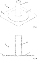
- a first exemplary embodiment of a bushing P has a pipe section 1 on which a plate 2 is formed.
- This plate 2 sits on a mat 3, which is an approximately rectangular piece of bitumen sheeting in the embodiment shown.
- This mat 3 is to be intimately connected to the plate 2 of the implementation P, so that when this implementation P is subsequently used, the mat 3 can be connected in a simple way to a roof covering not shown in detail, which, for example, can be used in a connection of bitumen with the mat bitumen of the roof covering is done by simply heating it up using a gas burner.
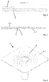
- the operation of the present invention is as follows: The production of the pipe section 1 together with the plate 2 should take place in an injection molding machine. According to the invention, the mat 3 is inserted into this injection mold before the material for the pipe section 1 and the plate 2 is introduced, and then the material for the pipe section 1 and the plate 2 is introduced. Due to the high mass temperature of the injected plastic, the bitumen mat 3 is melted, so that an intimate connection between plate 2 and mat 3 is created, as is shown in figure 3 is indicated.
- a sub-plate 8 is assigned to the plate 2, with the corresponding material for the two plates 2 and 8 openings 4 in a mat 3.3. flows through.
- the lower plate 8 is provided with a flattening 9 on the outside.
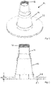
- the present invention is also suitable for feedthroughs P4, which in turn are suitable for an object, for example a pipeline, to be passed through them.
- the passage P4 has a conically narrowing guide 10, onto which a plate 2.2 and a lower plate 8.1 are formed.
- Plate 2.2 and lower plate 8.1 keep a distance a, in which a mat, not shown in detail, can be inserted, with a figure 7 shown connection possibility between the plates 2.2 and 8.1 is preferred.
- a sealing element 11 is clipped onto the guide 10, in the interior of which sealing rings 12 are provided, which in the position of use, for example, closely enclose a pipe and thus seal it. Protection is also sought separately for this sealing element 11 .
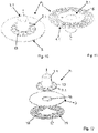
- FIG. 10 Another implementation of the invention P5 has according to the Figures 10 and 11 a pipe section 1.1, to which the mat 3 is assigned, with the pipe section 1.1 reaching through the mat 3 approximately in the middle and on the other hand the mat 3 is connected to a plate 2.1, preferably in one piece, with this plate 2.1 reaching under the mat 3.
- a grid 13 is formed on the pipe section 1.
- an induction element 15 which is circular in the present exemplary embodiment and has openings 16.
- the production of this implementation P5 is based on figure 12 explained in more detail, but this is only one embodiment.
- the mat 3 and the induction element 15 are placed in a corresponding mold of an injection mold in the corresponding mold cavity.
- the induction element 15 has corresponding centering holes 17, via which the induction element 15 is adjusted in shape.
- the injection process of the plastic mass for the plate 2.1, the pipe section 1.1 and the grid 13 now takes place, with the mass for the grid 13 and the pipe section 1.1 flowing through the central opening 18 of the mat 3.
- pipe section 1.1, mat 3, grid 13 and plate 2.1 are connected to form a unit that can be placed, for example, over a corresponding opening in a flat roof of a building on the roofing membrane located there, for example made of bitumen.
- an induction device (not shown in detail) is placed on the mat 3, which heats up the induction element 15 so that both the mat 3, which is preferably also made of bitumen, is melted and the roof sheeting is heated until it is melted. so that both connect through the openings 16 through intimately with each other.
- the weight of the induction device is selected or that of the induction device
- the pressure exerted is set so that the surfaces to be connected are securely pressed together.
Landscapes
- Engineering & Computer Science (AREA)
- Architecture (AREA)
- Civil Engineering (AREA)
- Structural Engineering (AREA)
- General Engineering & Computer Science (AREA)
- Mechanical Engineering (AREA)
- Tents Or Canopies (AREA)
- Lining Or Joining Of Plastics Or The Like (AREA)
Applications Claiming Priority (1)
| Application Number | Priority Date | Filing Date | Title |
|---|---|---|---|
| DE102021104470 | 2021-02-25 |
Publications (2)
| Publication Number | Publication Date |
|---|---|
| EP4050176A1 true EP4050176A1 (fr) | 2022-08-31 |
| EP4050176B1 EP4050176B1 (fr) | 2025-09-24 |
Family
ID=80461605
Family Applications (1)
| Application Number | Title | Priority Date | Filing Date |
|---|---|---|---|
| EP22158754.6A Active EP4050176B1 (fr) | 2021-02-25 | 2022-02-25 | Procédé de fabrication d'une traversée à travers un revêtement de toiture |
Country Status (2)
| Country | Link |
|---|---|
| EP (1) | EP4050176B1 (fr) |
| DE (1) | DE102022104536A1 (fr) |
Families Citing this family (1)
| Publication number | Priority date | Publication date | Assignee | Title |
|---|---|---|---|---|
| DE102023109553A1 (de) | 2023-04-17 | 2024-10-17 | Dennis Krasemann | Wanddurchführung für Blitzableiter |
Citations (3)
| Publication number | Priority date | Publication date | Assignee | Title |
|---|---|---|---|---|
| DE19634453A1 (de) * | 1996-08-26 | 1998-03-12 | Sfs Ind Holding Ag | Anordnung zur Befestigung von Abdeck- und/oder Abdichtungsbahnen |
| US20120233958A1 (en) * | 2011-03-15 | 2012-09-20 | Brian Cecil Stearns | Roof mount assembly |
| WO2015082680A1 (fr) * | 2013-12-05 | 2015-06-11 | De Boer Waterproofing Solutions Nv | Procédé pour imperméabiliser une couverture de toit |
-
2022
- 2022-02-25 EP EP22158754.6A patent/EP4050176B1/fr active Active
- 2022-02-25 DE DE102022104536.6A patent/DE102022104536A1/de active Pending
Patent Citations (3)
| Publication number | Priority date | Publication date | Assignee | Title |
|---|---|---|---|---|
| DE19634453A1 (de) * | 1996-08-26 | 1998-03-12 | Sfs Ind Holding Ag | Anordnung zur Befestigung von Abdeck- und/oder Abdichtungsbahnen |
| US20120233958A1 (en) * | 2011-03-15 | 2012-09-20 | Brian Cecil Stearns | Roof mount assembly |
| WO2015082680A1 (fr) * | 2013-12-05 | 2015-06-11 | De Boer Waterproofing Solutions Nv | Procédé pour imperméabiliser une couverture de toit |
Also Published As
| Publication number | Publication date |
|---|---|
| EP4050176B1 (fr) | 2025-09-24 |
| DE102022104536A1 (de) | 2022-08-25 |
Similar Documents
| Publication | Publication Date | Title |
|---|---|---|
| DE69004195T2 (de) | Doppelwandsystem für einen Wasserbehälter. | |
| DE1658883A1 (de) | Verfahren zum Befestigen einer Deck- oder Isolationsfolie | |
| DE102012217874A1 (de) | Vorrichtung zur Führung eines Fluids | |
| EP4050176A1 (fr) | Procédé de fabrication d'une traversée à travers un revêtement de toiture | |
| DE3527440C1 (de) | Verfahren zur Herstellung einer fluessigkeits- und gasdichten Verbindung zwischen Kunststoffrohren und Verbindungsstuecken | |
| DE60214838T2 (de) | Verfahren zur verbindung von vorgefertigten, wärmeisolierten rohren, die verbindung an sich und ein rohrteil, das die besagte verbindung enthält | |
| EP3428355B1 (fr) | Dispositif de vidange avec un écoulement à collier d'étanchéité et procédé de fabrication d'un dispositif de vidange | |
| AT523833B1 (de) | Rohrdurchführung durch ein Bauwerks-Trennelement | |
| CH675850A5 (fr) | ||
| DE19504139C2 (de) | Verfahren zur Abdichtung des Überganges zwischen einer Anschlußleitung und PE-Rohren und Anschlußdichtung | |
| DE3733237A1 (de) | Mantelrohrdurchfuehrung durch das mauerwerk von haus- u. dgl. waenden | |
| DE20015281U1 (de) | Einfassung für eine Abdichtungsbahn | |
| DE102004061743A1 (de) | Dichtungsmaterialien und Verschlußverfahren | |
| DE4139629A1 (de) | Abdichtvorrichtung fuer fugen zwischen bauteilen | |
| DE102013219558A1 (de) | Vorrichtung zur Führung eines Fluids | |
| DE2935782A1 (de) | Eckwinkel fuer profile. | |
| DE29712770U1 (de) | Eckteil für Übergänge zwischen unterschiedlich geneigten Flächen oder Bauteilen von Bauwerken | |
| DE69100542T3 (de) | Muffenrohr aus Kunststoff sowie Herstellungsverfahren dafür. | |
| DE2740291A1 (de) | Verfahren und vorrichtung zum verbinden von kunststoffkoerpern mit bindemittelhaltigen formteilen aus beispielsweise beton oder zement | |
| EP3372885A1 (fr) | Élement d'étanchéité | |
| EP2273206A2 (fr) | Eléments plat | |
| DE102004020758A1 (de) | Schelle aus thermisch schweißfähigem Material | |
| DE4430040C2 (de) | Einbauelement zur Anordnung in Bodenschichten mit einem durchströmbaren Gehäuse | |
| DE102007026729A1 (de) | Vorrichtung zur Durchführung einer Rohrleitung oder dergleichen durch ein Dach | |
| DE102020124563A1 (de) | Wurzelsicheres Leitungsschutzrohr für Versorgungsleitungen |
Legal Events
| Date | Code | Title | Description |
|---|---|---|---|
| PUAI | Public reference made under article 153(3) epc to a published international application that has entered the european phase |
Free format text: ORIGINAL CODE: 0009012 |
|
| STAA | Information on the status of an ep patent application or granted ep patent |
Free format text: STATUS: THE APPLICATION HAS BEEN PUBLISHED |
|
| AK | Designated contracting states |
Kind code of ref document: A1 Designated state(s): AL AT BE BG CH CY CZ DE DK EE ES FI FR GB GR HR HU IE IS IT LI LT LU LV MC MK MT NL NO PL PT RO RS SE SI SK SM TR |
|
| STAA | Information on the status of an ep patent application or granted ep patent |
Free format text: STATUS: REQUEST FOR EXAMINATION WAS MADE |
|
| 17P | Request for examination filed |
Effective date: 20221018 |
|
| RBV | Designated contracting states (corrected) |
Designated state(s): AL AT BE BG CH CY CZ DE DK EE ES FI FR GB GR HR HU IE IS IT LI LT LU LV MC MK MT NL NO PL PT RO RS SE SI SK SM TR |
|
| GRAP | Despatch of communication of intention to grant a patent |
Free format text: ORIGINAL CODE: EPIDOSNIGR1 |
|
| STAA | Information on the status of an ep patent application or granted ep patent |
Free format text: STATUS: GRANT OF PATENT IS INTENDED |
|
| INTG | Intention to grant announced |
Effective date: 20250415 |
|
| GRAS | Grant fee paid |
Free format text: ORIGINAL CODE: EPIDOSNIGR3 |
|
| GRAA | (expected) grant |
Free format text: ORIGINAL CODE: 0009210 |
|
| STAA | Information on the status of an ep patent application or granted ep patent |
Free format text: STATUS: THE PATENT HAS BEEN GRANTED |
|
| AK | Designated contracting states |
Kind code of ref document: B1 Designated state(s): AL AT BE BG CH CY CZ DE DK EE ES FI FR GB GR HR HU IE IS IT LI LT LU LV MC MK MT NL NO PL PT RO RS SE SI SK SM TR |
|
| REG | Reference to a national code |
Ref country code: GB Ref legal event code: FG4D Free format text: NOT ENGLISH |
|
| REG | Reference to a national code |
Ref country code: CH Ref legal event code: EP |
|
| REG | Reference to a national code |
Ref country code: DE Ref legal event code: R096 Ref document number: 502022005538 Country of ref document: DE |
|
| REG | Reference to a national code |
Ref country code: IE Ref legal event code: FG4D Free format text: LANGUAGE OF EP DOCUMENT: GERMAN |
|
| PG25 | Lapsed in a contracting state [announced via postgrant information from national office to epo] |
Ref country code: NO Free format text: LAPSE BECAUSE OF FAILURE TO SUBMIT A TRANSLATION OF THE DESCRIPTION OR TO PAY THE FEE WITHIN THE PRESCRIBED TIME-LIMIT Effective date: 20251224 |
|
| REG | Reference to a national code |
Ref country code: LT Ref legal event code: MG9D |
|
| PG25 | Lapsed in a contracting state [announced via postgrant information from national office to epo] |
Ref country code: FI Free format text: LAPSE BECAUSE OF FAILURE TO SUBMIT A TRANSLATION OF THE DESCRIPTION OR TO PAY THE FEE WITHIN THE PRESCRIBED TIME-LIMIT Effective date: 20250924 |
|
| PG25 | Lapsed in a contracting state [announced via postgrant information from national office to epo] |
Ref country code: HR Free format text: LAPSE BECAUSE OF FAILURE TO SUBMIT A TRANSLATION OF THE DESCRIPTION OR TO PAY THE FEE WITHIN THE PRESCRIBED TIME-LIMIT Effective date: 20250924 |
|
| PG25 | Lapsed in a contracting state [announced via postgrant information from national office to epo] |
Ref country code: GR Free format text: LAPSE BECAUSE OF FAILURE TO SUBMIT A TRANSLATION OF THE DESCRIPTION OR TO PAY THE FEE WITHIN THE PRESCRIBED TIME-LIMIT Effective date: 20251225 |
|
| PG25 | Lapsed in a contracting state [announced via postgrant information from national office to epo] |
Ref country code: SE Free format text: LAPSE BECAUSE OF FAILURE TO SUBMIT A TRANSLATION OF THE DESCRIPTION OR TO PAY THE FEE WITHIN THE PRESCRIBED TIME-LIMIT Effective date: 20250924 |
|
| PG25 | Lapsed in a contracting state [announced via postgrant information from national office to epo] |
Ref country code: LV Free format text: LAPSE BECAUSE OF FAILURE TO SUBMIT A TRANSLATION OF THE DESCRIPTION OR TO PAY THE FEE WITHIN THE PRESCRIBED TIME-LIMIT Effective date: 20250924 |
|
| PG25 | Lapsed in a contracting state [announced via postgrant information from national office to epo] |
Ref country code: BG Free format text: LAPSE BECAUSE OF FAILURE TO SUBMIT A TRANSLATION OF THE DESCRIPTION OR TO PAY THE FEE WITHIN THE PRESCRIBED TIME-LIMIT Effective date: 20250924 |
|
| PG25 | Lapsed in a contracting state [announced via postgrant information from national office to epo] |
Ref country code: RS Free format text: LAPSE BECAUSE OF FAILURE TO SUBMIT A TRANSLATION OF THE DESCRIPTION OR TO PAY THE FEE WITHIN THE PRESCRIBED TIME-LIMIT Effective date: 20251224 |
|
| REG | Reference to a national code |
Ref country code: NL Ref legal event code: MP Effective date: 20250924 |
|
| PG25 | Lapsed in a contracting state [announced via postgrant information from national office to epo] |
Ref country code: NL Free format text: LAPSE BECAUSE OF FAILURE TO SUBMIT A TRANSLATION OF THE DESCRIPTION OR TO PAY THE FEE WITHIN THE PRESCRIBED TIME-LIMIT Effective date: 20250924 |
|
| PG25 | Lapsed in a contracting state [announced via postgrant information from national office to epo] |
Ref country code: SM Free format text: LAPSE BECAUSE OF FAILURE TO SUBMIT A TRANSLATION OF THE DESCRIPTION OR TO PAY THE FEE WITHIN THE PRESCRIBED TIME-LIMIT Effective date: 20250924 |
|
| PG25 | Lapsed in a contracting state [announced via postgrant information from national office to epo] |
Ref country code: ES Free format text: LAPSE BECAUSE OF FAILURE TO SUBMIT A TRANSLATION OF THE DESCRIPTION OR TO PAY THE FEE WITHIN THE PRESCRIBED TIME-LIMIT Effective date: 20250924 |
|
| PGFP | Annual fee paid to national office [announced via postgrant information from national office to epo] |
Ref country code: AT Payment date: 20260301 Year of fee payment: 5 |
|
| PG25 | Lapsed in a contracting state [announced via postgrant information from national office to epo] |
Ref country code: IT Free format text: LAPSE BECAUSE OF FAILURE TO SUBMIT A TRANSLATION OF THE DESCRIPTION OR TO PAY THE FEE WITHIN THE PRESCRIBED TIME-LIMIT Effective date: 20250924 |
|
| PG25 | Lapsed in a contracting state [announced via postgrant information from national office to epo] |
Ref country code: IS Free format text: LAPSE BECAUSE OF FAILURE TO SUBMIT A TRANSLATION OF THE DESCRIPTION OR TO PAY THE FEE WITHIN THE PRESCRIBED TIME-LIMIT Effective date: 20260124 |
|
| PG25 | Lapsed in a contracting state [announced via postgrant information from national office to epo] |
Ref country code: CZ Free format text: LAPSE BECAUSE OF FAILURE TO SUBMIT A TRANSLATION OF THE DESCRIPTION OR TO PAY THE FEE WITHIN THE PRESCRIBED TIME-LIMIT Effective date: 20250924 Ref country code: PT Free format text: LAPSE BECAUSE OF FAILURE TO SUBMIT A TRANSLATION OF THE DESCRIPTION OR TO PAY THE FEE WITHIN THE PRESCRIBED TIME-LIMIT Effective date: 20260126 |
|
| PG25 | Lapsed in a contracting state [announced via postgrant information from national office to epo] |
Ref country code: PL Free format text: LAPSE BECAUSE OF FAILURE TO SUBMIT A TRANSLATION OF THE DESCRIPTION OR TO PAY THE FEE WITHIN THE PRESCRIBED TIME-LIMIT Effective date: 20250924 |
|
| PG25 | Lapsed in a contracting state [announced via postgrant information from national office to epo] |
Ref country code: EE Free format text: LAPSE BECAUSE OF FAILURE TO SUBMIT A TRANSLATION OF THE DESCRIPTION OR TO PAY THE FEE WITHIN THE PRESCRIBED TIME-LIMIT Effective date: 20250924 Ref country code: SK Free format text: LAPSE BECAUSE OF FAILURE TO SUBMIT A TRANSLATION OF THE DESCRIPTION OR TO PAY THE FEE WITHIN THE PRESCRIBED TIME-LIMIT Effective date: 20250924 |