EP4050178B1 - Wandverkleidungssystem - Google Patents
Wandverkleidungssystem Download PDFInfo
- Publication number
- EP4050178B1 EP4050178B1 EP21210252.9A EP21210252A EP4050178B1 EP 4050178 B1 EP4050178 B1 EP 4050178B1 EP 21210252 A EP21210252 A EP 21210252A EP 4050178 B1 EP4050178 B1 EP 4050178B1
- Authority
- EP
- European Patent Office
- Prior art keywords
- leg
- metal profile
- metal
- profile
- wall cladding
- Prior art date
- Legal status (The legal status is an assumption and is not a legal conclusion. Google has not performed a legal analysis and makes no representation as to the accuracy of the status listed.)
- Active
Links
Images


Classifications
-
- E—FIXED CONSTRUCTIONS
- E04—BUILDING
- E04F—FINISHING WORK ON BUILDINGS, e.g. STAIRS, FLOORS
- E04F13/00—Coverings or linings, e.g. for walls or ceilings
- E04F13/07—Coverings or linings, e.g. for walls or ceilings composed of covering or lining elements; Sub-structures therefor; Fastening means therefor
- E04F13/08—Coverings or linings, e.g. for walls or ceilings composed of covering or lining elements; Sub-structures therefor; Fastening means therefor composed of a plurality of similar covering or lining elements
- E04F13/0801—Separate fastening elements
- E04F13/0803—Separate fastening elements with load-supporting elongated furring elements between wall and covering elements
- E04F13/081—Separate fastening elements with load-supporting elongated furring elements between wall and covering elements with additional fastening elements between furring elements and covering elements
- E04F13/0821—Separate fastening elements with load-supporting elongated furring elements between wall and covering elements with additional fastening elements between furring elements and covering elements the additional fastening elements located in-between two adjacent covering elements
- E04F13/0826—Separate fastening elements with load-supporting elongated furring elements between wall and covering elements with additional fastening elements between furring elements and covering elements the additional fastening elements located in-between two adjacent covering elements engaging side grooves running along the whole length of the covering elements
-
- E—FIXED CONSTRUCTIONS
- E04—BUILDING
- E04F—FINISHING WORK ON BUILDINGS, e.g. STAIRS, FLOORS
- E04F13/00—Coverings or linings, e.g. for walls or ceilings
- E04F13/07—Coverings or linings, e.g. for walls or ceilings composed of covering or lining elements; Sub-structures therefor; Fastening means therefor
- E04F13/08—Coverings or linings, e.g. for walls or ceilings composed of covering or lining elements; Sub-structures therefor; Fastening means therefor composed of a plurality of similar covering or lining elements
- E04F13/0889—Coverings or linings, e.g. for walls or ceilings composed of covering or lining elements; Sub-structures therefor; Fastening means therefor composed of a plurality of similar covering or lining elements characterised by the joints between neighbouring elements, e.g. with joint fillings or with tongue and groove connections
- E04F13/0891—Coverings or linings, e.g. for walls or ceilings composed of covering or lining elements; Sub-structures therefor; Fastening means therefor composed of a plurality of similar covering or lining elements characterised by the joints between neighbouring elements, e.g. with joint fillings or with tongue and groove connections with joint fillings
-
- E—FIXED CONSTRUCTIONS
- E04—BUILDING
- E04F—FINISHING WORK ON BUILDINGS, e.g. STAIRS, FLOORS
- E04F2201/00—Joining sheets or plates or panels
- E04F2201/02—Non-undercut connections, e.g. tongue and groove connections
- E04F2201/023—Non-undercut connections, e.g. tongue and groove connections with a continuous tongue or groove
Definitions
- the invention relates to a wall cladding system, a facade wall provided with a wall cladding system, and a set of parts.
- a wall cladding system is attached to a facade wall.
- structural walls can be clad with a wall cladding system.
- This wall cladding system provides for instance for the aesthetic design of the wall, and gives the building a particular appearance where often one or more materials are central in the eventual appearance of the building. In this context, wood is a frequently used material.
- Wall cladding systems must comply with defined standards, which have constantly become more stringent over the years. Which is why constantly achieving these standards continues to be a challenge.
- An important standard for a wall cladding system is the fire reaction of the wall cladding system, as for instance laid down in NBN EN 13501-1, for which Single Burning Item (SBI) tests according to standard ('norm') EN 13823 are necessary.
- SBI Single Burning Item
- 'norm' Standard
- a defined fire reaction class is awarded to the tested wall cladding system.
- Most wall cladding systems are in fire reaction classes D - F.
- Wood is a relatively combustible material compared with alternative materials such as plastic or metal. That is why wall cladding systems that comprise wood are known for their disadvantageous fire reaction. In particular, this has as a consequence that wood is rarely used in larger constructions and/or in commercial and industrial buildings. Therefore, for such wall cladding systems wood is used that has undergone a fire-retardant treatment. However, fire-retardant impregnation of wood only provides for a limited delay of the fire reaction, as the fire retardants rapidly disappear from the wood in the event of fire.
- a known solution for improving the fire reaction is to impregnate the wood with fire-retardant salts. These fire-retardant salts ensure that a non-metal profile can be exposed to a fire longer before igniting itself. Impregnating wood, however, raises the cost price of the non-metal wall cladding considerably. It is a relatively expensive, and not always environmentally friendly treatment of the wood. Some manners of impregnating are, on top of that, only a temporary solution, for wood that has been impregnated in such a manner may leach, whereby the fire-retardant salts will have been extracted from the wood almost completely after a number of years. After this, the leached wood is as combustible again as before the impregnation process, with a disadvantageous fire reaction as a consequence.
- Document FR 2433087 discloses a system for fixation of panels to a wall, having a profile to which the panels can be attached.
- the profile comprises a T-shape branch for receiving the panels, and has a transverse wedge-shaped arm through which a screw for fastening the profile to the wall can be received.
- Document WO 89/03462 discloses a device for facing a wall structure wherein panel elements are connected to a fastening sections.
- the fastening sections have branches that can be received in grooves in the elements, and an inclined branch for fastening to the wall structure.
- Document BE1026656B1 discloses an attachment profile for slats, wherein the attachment profile comprises a corner profile having a first and a second leg.
- a wall cladding system according to claim 1.
- the contact surface between metal profile and non-metal profile is made as large as possible.
- optimal heat transfer is possible from the non-metal profiles to the metal profiles.
- a relatively good fire reaction class can be achieved. Due to the clamping of the metal profile in the non-metal profiles, and the succession of non-metal and metal profiles, a complete outer shell can be formed which can screen structures present behind it, such as fastening system, or a wall, from environmental influences, including wind, rain, dirt, fire, etc.
- a system according to the invention gives an improved fire reaction when the non-metal profile is a wooden profile, more preferably a non-treated wooden profile. Additionally, the inventor found that other non-metal profiles, such as bamboo or plastic, in the wall cladding system also led to an improved fire reaction.
- a non-metal profile having a rounding and/or bevel has a considerably lower fire reaction. Due to the rounding and/or the bevel of the non-metal profiles, the heat conduction of the hot air during any fire is improved. As a consequence, the heat accumulates less fast and so it takes longer before the non-metal profile catches fire. A favorable fire reaction is thereby achieved.
- the rounding has a radius of between 1 and 10 mm, preferably between 2 and 5 mm, more preferably of 3 mm.
- the bevel can have an angle of between 25 - 60 degrees, preferably between 30 - 50 degrees, more preferably approximately 45 degrees.
- the inventor found the above spatial values to be favorable to the fire reaction. At these values, an optimal improvement of the heat conduction is achieved, in consequence of which the fire reaction becomes favorable.
- a rounding or a bevel according to these values has little influence on for instance the mechanical strength of the non-metal profile. Also, the aesthetic impact of a rounding or a bevel according to these values is relatively limited.
- the wall cladding system may be provided against an outer facade, an inner facade, an inner wall, an outer wall, a ceiling, a roof.
- the walls can be straight or oblique or lying.
- a wall, of a building is regarded as an exterior of the building, and can be an outer facade or a roof and/or can also be regarded as an interior of the building, for instance an inner wall, inner facade or ceiling.
- a closed wall cladding system can be obtained which can screen inter alia any wall fastening system present behind it from environmental influences. If the wall fastening system is screened, the fire requirements for that system may cease to be applicable. Also, the metal profiles can keep the non-metal profiles optimally stable, especially when these are exposed to extreme conditions, such as extreme temperatures in case of fire. Since the non-metal profile and the metal profile react in different ways to such conditions, the metal profile can guard the non-metal profile against for instance torsion resulting from the heat.
- the wall cladding system can also be advantageously used as a roof cladding system.
- a roof of a building is then first sealed with a roof sealing, for instance a moisture-proof cloth, such as EPDM.
- the roof wall has thereby been rendered closed so that environmental influences, wind, rain, dirt, etc. keep out.
- the fastening system such as for instance a non-metal or aluminium framework, is thereupon mounted on the roof, which causes perforations in the roof sealing.
- a closed shell is achieved, so that environmental influences are kept away from any fastening system present behind it.
- the roof despite the perforations in the roof sealing, yet remains tight to environmental influences, such as rain, wind, dirt, UV light, etc. Because also UV light does not reach the roof sealing anymore due to the wall cladding system, the life span of the roof sealing can be prolonged. Also, by providing a tight shell that is the wall cladding system, this can prevent fire particles flying around, also described as wind-spread fire, from reaching the roof sealing, which could thereby catch fire. This is also beneficial to safety. By making use of the wall cladding system, such wind-spread fire is stopped on an outer side thereof, also having a fire-retardant configuration.
- the non-metal profiles can be untreated non-metal profiles.
- Untreated non-metal profiles are not only more favorable in cost but also environment-friendlier than for instance profiles impregnated with fire-retarding salts, because of the absence of the fire-retarding salts. Due to the rounding and/or the bevel, even with untreated non-metal profiles a favorable fire reaction can be achieved in fire tests, for instance a fire test according to standard NBN EN 13823 for Single Burning Item tests (SBI tests). With the profiles according to the invention, it is even possible, with an SBI test according to standard EN 13823, to achieve a classification as follows: fire class A2/B; smoke class s1; flaming particles d0.
- the inventor has had several SBI tests according to standard EN 13823 performed on a wall cladding system with untreated afrormosia wood, with beveled sides and with rounding radius 3 mm, and a powder lacquered aluminium profile (RAL9005 in conformity with Qualicoat Seaside), horizontally mounted on a non-metal framework as fastening system. According to this test, the tested system thereby falls into fire class A2/B; smoke class s1; flaming particles d0. This is a result that to date has been considered impossible for a wall cladding system with untreated wood, also by academia and knowledge institutes. Also SBI tests with afzelia, i regards and okan have been performed, and for them fire class B was achieved.
- a non-metal profile may be manufactured from wood, but may for instance also be manufactured from bamboo or for instance also from composite plastic material.
- a bamboo profile is manufactured from pressed bamboo. Bamboo is considered a type of grass which in combination with glue is pressed to form a, for instance, plank profile.
- glue usually entails a higher heat development in case of fire, but by using such a bamboo profile in combination with the metal profile of the invention, still a sufficient fire reaction class can be achieved. This can make a bamboo profile applicable as wall cladding.
- the non-metal profiles are described, for example, as beam-shaped. Because of the ratio between the different dimensions of the non-metal profiles, however, the non-metal profiles will mainly approximate a plank-shaped profile. It will be clear to one skilled in the art, however, that beam-shaped can also be read as plank-shaped.
- the metal profile can be an aluminium profile.
- An aluminium profile has the advantage of conducting heat well.
- the aluminium profile as such can remove heat from a non-metal profile.
- the aluminium profile slows the heating up of an adjacent non-metal profile by dissipating a part of the heat transferred to the non-metal profile again. Owing to the aluminium profile, therefore, it takes longer before the non-metal profile reaches an ignition point, so that spread of the fire is slowed up.
- the aluminium profile thus contributes to a further lowering of the fire reaction.
- the use of aluminium results furthermore in relatively light metal profiles vis-à-vis other metal profiles that are for instance manufactured from iron or steel.
- an aluminium profile because of the natural corrosion resistance of aluminium, is highly suitable to resist the weather conditions.
- the metal profile can be provided with a coating.
- This coating may be a fire-resistant coating.
- fire-resistant coatings are known.
- a chemical reaction takes place whereby the coating is converted into an insulating foam.
- This insulating foam can then, at least temporarily, prevent a hot airflow from reaching the non-metal profile. Because less heat reaches the non-metal profile, it will take longer before the non-metal product ignites, and the spread of a fire is delayed. The fire reaction can thus be further lowered.
- a coating can screen the aluminium profile from weather conditions, which is of benefit to the durability of the aluminium profile and the wall cladding system as a whole. It will be clear, however, that this fire-resistant coating does not necessarily have to be present for improving the fire reaction of the wall cladding system. This can also be achieved without fire-retardant coating.
- the aluminium profile may, instead of or in addition to having a coating, be anodized. The aluminium profile can be advantageously produced via extrusion. Thus, its production can remain relatively simple and relatively inexpensive.
- Each of the at least two non-metal profiles comprises in the first and/or the second side a recess for receiving at least a part of the metal profile.
- each of the at least two non-metal profiles can comprise in the side opposite to the side with the recess a second recess for receiving at least a part of a second metal profile.
- This recess facilitates placing of the wall cladding system.
- a non-metal profile or a metal profile can be relatively simply attached to an already placed profile by inserting a part of the metal profile in the recess.
- the recess also makes clear which side of the non-metal profile is to be connected with the metal profile, thereby preventing the non-metal profiles being connected with a metal profile in a non-correct manner.
- the metal profile comprises a first leg and a second leg which are each insertable in the recess of one of the non-metal profiles.
- the first leg of the metal profile may be configured to be receivable in a recess in the first side of the non-metal profile
- the second leg of the metal profile is configured to be receivable in a recess in the second side of the non-metal profile.
- the first leg and the second leg enlarge the contact surface between the metal profile and the non-metal profile. Consequently, more heat can be led via conduction from the non-metal profile to the metal profile, in particular when the metal profile is a highly heat-conductive profile, such as an aluminium profile.
- the first leg and the second leg in a way serve as cooler for the non-metal profile.
- the total amount of heat that a non-metal profile must absorb to ignite thereby increases, because a part of the absorbed heat is removed again via the first leg and the second leg.
- the first leg and the second leg are favorable to the fire reaction of the non-metal profile.
- the first leg and the second leg of the metal profile can impart stability to the non-metal profile.
- a non-metal profile that is exposed to extreme heat, as in a fire, will tend to deform.
- the first leg and the second leg will, at least partly, hinder deforming of the non-metal profile.
- the stability of the wall cladding system as a whole is thereby increased.
- the non-metal and the metal profiles can hence upon exposure to extreme heat more firmly clamp in each other.
- the first leg and the second leg facilitate furthermore the placing of the wall cladding system. Due to the first leg and the second leg, it is also clear for the metal profile how it is to be connected with the non-metal profiles, thereby preventing the metal profile being connected with a non-metal profile in a non-correct manner.
- Each of the first leg and the second leg of the metal profile may comprise a projection, such that each of the at least two legs is clampingly receivable in the recess of one of the first side and the second side of the non-metal profiles.
- a non-metal profile and a metal profile form a fixed whole once the first or the second leg of the metal profile has been clampingly received in a recess of the non-metal profile.
- further connecting steps are not necessarily needed.
- the wall cladding system can for instance be so configured that merely the metal profiles need to be fixedly connected to a facade wall, because a non-metal profile is already fixed by being clampingly connected along both sides with a metal profile.
- the projection may be present on a first side of each of the first leg and the second leg, such that a second side of each of the first leg and the second leg opposite to the first side can form a contact surface with a side of the recess proximal to the front side of the non-metal profile.
- the contact surface is accordingly located on the side of the recess where most heat develops in case of fire, viz. on the side remote from the facade wall, that is, the side proximal to the front side.
- the first leg and the second leg can consequently remove heat from the non-metal profile faster than if the projection were on the other side of the first leg and the second leg.
- the at least two non-metal profiles can comprise in the side opposite to the side with the recess a projecting portion configured to be received by a part of the metal profile.
- the projecting portion provides an alternative manner of clearly indicating how the non-metal profile is to be connected with the metal profile, thereby preventing the metal profile being connected with a non-metal profile in a non-correct manner.
- the metal profile furthermore comprises a third leg, the third leg being approximately parallel with the first leg, so that between the first leg and the third leg is a receiving cavity in which a part of a non-metal profile can be received, or in which the projecting portion of a non-metal profile can be clampingly received.
- the third leg enlarges, just like the first and the second leg, the contact surface between the non-metal profile and the metal profile.
- the third leg also removes heat and enhances the cooling effect of the first leg and the second leg, and hence is favorable to the fire reaction of the non-metal profile.
- the third leg of the metal profile can abut against the rear side of the non-metal profile, so as to further enlarge the contact surface between wood and metal profile.
- the third leg then effectively faces the facade wall, and may as such be simply used to connect the metal profile with the facade wall, as is further explained hereinbelow.
- the non-metal profile does not extend all the way up to the end of the receiving cavity, but there is a distance between the non-metal profile and an end side of the third leg, to be able to accommodate any warp of the wood.
- the long side of the third leg by contrast, preferably abuts as completely as possible against the non-metal profile in order to effect heat conduction.
- a facade fastening system may be arranged, against which the wall cladding system can be attached.
- the third leg of the metal profile comprises a trough for recessed receiving of a fastener for fastening the metal profile to a facade wall.
- each of the at least two non-metal profiles may be provided with a flange extending from the second side, through which a fastener for fastening with the facade wall is receivable.
- the trough and the flange can facilitate the connection of the wall cladding system with the facade wall. It will be clear, however, that the wall cladding system can also be attached to the facade wall in other ways without departing from the scope of protection of the claims.
- the wall cladding system can comprise a plurality of non-metal profiles and a plurality of metal profiles, wherein each non-metal profile is configured for connection with two metal profiles, and wherein each metal profile is configured for connection with two non-metal profiles to obtain a system with a non-metal profile and a metal profile in succession.
- This system can for instance be obtained by placing a first metal profile, connecting to this first metal profile a first non-metal profile, connecting to this first non-metal profile a second metal profile, connecting to this second metal profile a second non-metal profile, and so forth.
- An advantage of this system is that the total surface area covered by the system directly depends on the number of non-metal profiles and metal profiles.
- the system may thus be simply placed on facades of various dimensions by adjusting the number of non-metal profiles and metal profiles to the dimensions of the facade. In this way, a whole wall, outer wall and/or roof, inner wall and/or ceiling, can be clad with the wall cladding system.
- a facade wall provided with a wall cladding system as described above.
- the facade wall can furthermore comprise a fastening system configured for attaching the wall cladding system to the facade wall.
- the fastening system can for instance be a framework, or a system of battens that is placed against the facade, and against which the wall cladding system can be mounted. The fastening system is then eventually between the wall cladding system and the facade.
- the fastening system should comply with the national regulations for wall cladding, as issued by WTCB in Belgium and Centrum Hout in the Netherlands.
- the fastening system can consist substantially of aluminium, preferably wherein the fastening system is provided with a coating, more preferably wherein the fastening system is provided with a fire-resistant coating.
- a fastening system from aluminium can conduct heat away from a wall cladding system that has been provided on a facade wall via this fastening system.
- the fastening system similarly to the metal profiles of the wall cladding system, can delay ignition of a non-metal profile, and thus lower the fire reaction.
- the space between wall and wall cladding system is ventilated, the fastening system present in this space can then be additionally cooled by the ventilating current.
- the aluminium fastening system in such a ventilated space can be properly cooled, which can have a supplementary fire-retardant effect.
- the elongate non-metal profiles and the elongate metal profiles of the wall cladding system can extend substantially in standing direction or be substantially in lying direction relative to the facade wall.
- the wall cladding system will be attached to the facade wall such that the elongate non-metal profiles and the elongate metal profiles are horizontal or vertical.
- the wall cladding system may equally well be mounted on the facade wall such that the elongate non-metal profiles and the elongate metal profiles have an oblique orientation.
- a set of parts comprising a plurality of elongate non-metal profiles and a plurality of elongate metal profiles, wherein each non-metal profile is configured for connection with the at least one metal profile, such that when the two non-metal profiles are connected with a same metal profile, the non-metal profiles are at a distance from each other with the metal profile therebetween, and wherein the non-metal profiles are substantially beam-shaped profiles comprising a front side and an opposite rear side in longitudinal direction of the non-metal profile, as well as a first side and an opposite second side which extend in longitudinal direction between the front side and the rear side, wherein the first and the second side are configured for connection with the metal profile, wherein at least one transition between the front side and the first side and/or between the front side and the second side and/or between the rear side and the first side and/or between the rear side and the second side is rounded and/or bevelled.
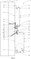
- FIG. 1 Each of the Figures 1 , 2 and 3 shows a schematic side view of a wall provided with a wall cladding system 1.
- the wall can be a facade wall, an outer wall, a roof, can be horizontally or vertically oriented, or can be oblique.
- the wall cladding system 1 is broadly usable in and/or on a building.
- the wall cladding system 1 is attached via a fastening system 2 to a facade 4.
- the fastening system 2 is schematically represented, and may for instance be a framework 2 that is easy to mount to the facade 4. Mounting the framework 2 may for instance only require that at a limited number of points of the facade 4 a hole is to be drilled for insertion of an anchoring element from which the framework 2 is to be suspended. Such an anchoring element can for instance extend through the facade 4, whereby it is achieved that a load-bearing connection between the facade 4 and the framework is formed.
- the framework 2 may then further provide for the simple taking up of the wall cladding system 1.
- a framework 2 provides for a simpler and safer way of mounting the wall cladding system 1 to the facade 4.
- the wall cladding system 1 represented in Figures 1 , 2 and 3 comprises at least two elongate non-metal profiles 6, 7 and an elongate metal profile 8, such as for instance an aluminium profile 8.
- the aluminium profile 8 is connected with the two non-metal profiles 6, 7, such that the two non-metal profiles 6, 7 are at a distance A from each other.
- This distance A is not necessarily equal between each two successive non-metal profiles 6, 7. Especially for aesthetic purposes, the distance A can vary over successive non-metal profiles.
- the non-metal profiles 6, 7 and the aluminium profile 8 together cover the fastening system 2 completely.
- the fastening system 2 as well as the facade 4 are thus screened from any fire by the profiles 6, 7, 8, and next profiles 6, 7, 8 connected therewith to be able thus to cover the whole facade wall.
- the fastening system 2 itself does not need to undergo any adaptations with a view to improving the fire reaction of the wall cladding system 1.
- a better fire reaction is attained, also if furthermore a "standard" fastening system is used.
- a user is therefore not forced to use an adapted fastening system in combination with the wall cladding system 1, but might make use of fastening systems already familiar to him.
- the non-metal profiles 6, 7 are untreated non-metal profiles 6, 7. More specifically, the non-metal profiles 6, 7 have not been treated with fire-retardant agents. Partly due to the use of the metal profile 8 according to the invention, yet a high fire reaction class can be reached with untreated wood, whereas in conventional wall cladding systems the wood always needs to have been treated to reach a sufficient fire reaction class.
- Each non-metal profile 6, 7 comprises a front side 10 and an opposite rear side 12, as well as a first side 14 and a second side 16 which extend between the front side 10 and the rear side 12.
- Figure 1 shows non-metal profiles 6, 7 which comprise a first rounding 24 where the front side 10 and the second side 16 meet, and a second rounding 40 there where the front side 10 and the first side 14 meet.
- a hot airflow comes about which passes heat of the burning non-metal profile 7 in the direction of the non-metal profile 6.
- the non-metal profile 6 absorbs heat from this hot airflow, but without initially catching fire itself. Only when a point of the non-metal profile 6 contains a particular amount of energy, i.e. heat, will this point catch fire spontaneously.
- the rounding 24 improves the heat conduction of the hot airflow. As a result, the heat accumulates less fast and so it takes longer for the non-metal profile 6 to catch fire.
- the rounding 24 of non-metal profile 7 has a radius R.
- This radius R can be between 1 and 10 mm, preferably between 2 and 5 mm, more preferably 3 mm.
- the radius R to prevent overcrowded figures, is merely indicated on the non-metal profile 7.
- the radius of the rounding 24 of the non-metal profile 6 can also be between 1 and 10 mm, preferably between 2 and 5 mm, more preferably 3 mm, though it should be noted that the radius R of the rounding 24 of a plurality of non-metal profiles need not necessarily be the same for each non-metal profile.
- a first non-metal profile can have a rounding 24 having a radius R of 3 mm
- a next non-metal profile can have a rounding 24 having a radius R of 5 mm.
- the radius R of the rounding 24 need not necessarily be equal to the radius R of the rounding 40. This variety of roundings may for instance be for aesthetic reasons.
- Figure 2 shows non-metal profiles 6, 7 which comprise a bevel 28.
- the bevel 28 promotes, as does the rounding 24, the conduction of a hot airflow along the non-metal profile 6.
- the bevel 28 of non-metal profile 7 has an angle H. This angle H can be between 25 - 60 degrees, preferably between 30 - 50 degrees, more preferably approximately 45 degrees.
- the angle H, to prevent overcrowded figures, is only indicated on the non-metal profile 7.
- the angle of the bevel 28 of the non-metal profile 6 can also be between 25 - 60 degrees, preferably between 30 - 50 degrees, more preferably approximately 45 degrees, though it should be noted that the angle H of the bevel 28 of a plurality of non-metal profiles need not necessarily be the same for each non-metal profile.
- a first non-metal profile can have a bevel 28 having an angle H of 40 degrees
- a next non-metal profile can have a bevel 28 having an angle H of 50 degrees.
- This variety of bevels may for instance be for aesthetic reasons.
- Figure 3 shows non-metal profiles 6, 7 which comprise a rounding 24 and a bevel 28.
- a combination of the rounding 24 and the bevel 28 may for instance be of interest for guiding hot air alongside a substantial portion of the second side 16 with a minimal removal of wood. While the influence of the rounding 24 and the bevel 28 is thus combined here, this need not necessarily lead to a better total conduction. Of course, the combination of the rounding 24 and the bevel 28 may also be of interest for purely aesthetic reasons.
- the metal profile 8 is an aluminium profile. Aluminium is a good heat conductor. Due to the contact between the aluminium profile 8 and the non-metal profile 6, heat will accumulate less fast in the non-metal profile 6, because a part of the heat absorbed by the non-metal profile 6 is dissipated again via the aluminium profile 8.
- the aluminium profile 8 may be provided with a coating, for example a fire-resistant coating.
- the fire-resistant coating may for instance be a fire-resistant paint arranged to form an insulating foam in case of fire. This insulating foam then fills, at least partly, the space between the second side 16 of the non-metal profile 6 and the first side 14 of the non-metal profile 7.
- the insulating foam then forms a physical barrier whereby flow of hot air from the first side 14 of the non-metal profile 7 to the second side 16 of the non-metal profile 6 is hindered.
- a coating can screen the aluminium profile 8 from weather conditions, which is of benefit to the durability of the aluminium profile 8 and the wall cladding system 1 as a whole. It will be clear, however, that this fire-resistant coating does not necessarily have to be present for improving the fire reaction of the wall cladding system. Also without fire-resistant coating, a favorable fire reaction can be achieved, for instance with anodization of the aluminium profile 8 instead of, or in addition to, a coating.
- the first side 14 and the second side 16 comprise respectively a first recess 18 and a second recess 19 for receiving the aluminium profile 8 between the two non-metal profiles 6, 7.
- the aluminium profile 8 includes to this end a first leg 20 and a second leg 22, wherein the first leg 20 is received in the second recess 19 of the second side 16 of the first non-metal profile 6, and wherein the second leg 22 is received in the first recess 18 of the first side 14 of the second non-metal profile 7.
- the first leg 20 and the second leg 22 enlarge the contact surface between the aluminium profile 8 and the non-metal profiles 6, 7. This promotes the heat transfer between the aluminium profile 8 and the non-metal profiles 6, 7, as a result of which a non-metal profile can be exposed to heat longer before catching fire.
- first leg 20 and the second leg 22 are in line with each other, so that both sides of the first leg 20 and the second leg 22 that face towards the front side form one flat side which faces towards the front side of the non-metal profiles.
- This side 8z is, after mounting of the profile 8 between two profiles 6, 7, partly visible, and partly in contact with the non-metal profile 6, 7.
- the two non-metal profiles 6, 7 are at a distance A from each other when they are connected with the aluminium profile 8, and this distance A can vary over successive non-metal profiles. Varying of the distance A over successive non-metal profiles can for instance be achieved by providing different aluminium profiles 8 where a length of the second leg 22 can be different for different aluminium profiles 8. Similarly, the dimensions of the front side 10 and the rear side 12 and/or the first side 14 and the second side 16 can vary between different non-metal profiles 6, 7 for aesthetic purposes. In Figures 1 , 2 and 3 , it is for instance represented that the non-metal profile 7 has a longer first side 14 and second side 16 than the non-metal profile 6.
- the facade 4 and the wall fastening system 2 are screened from the environment by the non-metal profiles 6, 7 and the aluminium profile 8.
- the consequence of this is that the facade 4 and the wall fastening system 2, in case of fire, are not exposed to a flame directly.
- the wall fastening system 2 does not need to comply with a defined fire requirement, and a simpler and/or cheaper wall fastening system can be used.
- the wall fastening system 2 as such has no influence on the fire reaction of the wall cladding system 1, and so the wall cladding system 1 prevents its advantageous fire reaction being undone because of a disadvantageous fire reaction of the wall fastening system 2.
- the first leg 20 and the second leg 22 each comprise a projection 26 such that each of the first leg 20 and the second leg 22 is clampingly receivable in, respectively, the second recess 19 of the first non-metal profile 6 and the first recess 18 of the second non-metal profile 7.
- the projection 26 is on a side of the first leg 20 or the second leg 22 facing towards the rear side of the non-metal profiles 6, 7, after mounting also facing towards the facade 4. Because of this, the contact surface between the legs 20, 22 and the recesses 18, 19 is formed on that side of the recesses 18, 19 where heat develops most in the event of a fire, viz. on the side remote from the facade wall, that is, facing frontwards.
- the legs 20, 22 can thus conduct heat away from the non-metal profile 6, 7 faster than if the projection 26 were on another side of the legs 20, 22.
- the projection 26 is on the first leg 20 and on the second leg 22 at a distance from the free end 20a, 22a of the first leg 20 and of the second leg 22, respectively. Consequently, the free end 20a, 22a is somewhat less thick than at the projection, and it can have a pilot function facilitating insertion into the corresponding recess 19, 18.
- the recesses 18, 19 can be made so as to taper inwardly, allowing the first leg 20 and the second leg 22 with the projections 26 to be clampingly received in the recesses.
- contact can be made on the side of the metal profile 8 facing towards the front side, with a side inside of the recess. Due to a contact surface as large as possible, in case of fire, as much heat transfer as possible can take place between the heat conductive material of the metal profile 8, and the less heat conductive material of the non-metal profiles 6, 7. Moreover, this heat conduction takes place near the front side, remote from the wall 4.
- each of the first leg 20 and the second leg 22 extend by approximately 10 - 12 mm into their respective recess 18, 19.
- the extending of the first leg 20 and the second leg 22 by approximately 10 - 12 mm into their respective recess 18, 19 ensures that the non-metal profiles 6, 7 under the influence of ambient temperatures can deform, in particular, can shrink, without the contact between the first leg 20 or the second leg 22 and their respective recess 18, 19 being broken.
- the recess in the non-metal profile is preferably about 10% of the length of the non-metal profile so as to be able to allow for any warp of the wood, under the influence of ambient conditions such as temperature.
- the length of approximately 10 to 12 mm of the leg that extends into the recess of the non-metal profile can take care of a proper sealing, also when the non-metal profile is going to warp.
- the aluminium profile 8 comprises furthermore a third leg 30 which comprises a first portion 30a which is parallel with the first leg 20 and comprises a second portion 30b which is perpendicular to the first leg 20.
- the first portion 30a of the third leg 30 abuts against the rear side 12 of the non-metal profile 6, and makes contact with the rear side 12 of the non-metal profile 6.
- the second portion 30b of the third leg 30 can abut against the second side 16 of the non-metal profile 6, but can also be at a distance therefrom.
- the third leg 30 enlarges the contact surface between non-metal profile 6 and the aluminium profile 8.
- the third leg 30 promotes the heat transfer between the non-metal profile 6 and the aluminium profile 8, as a result of which catching fire of the non-metal profile 6 is delayed.
- the third leg 30 extends beyond the first leg 20, that is, the third leg 30, in particular the first portion 30a of the third leg 30, is longer than the first leg 20.
- the non-metal profile 6 may to that end be provided with a projecting part 161, or a lip or a flange which fits into the receiving cavity 300.
- the projecting part 161 can be preferably clampingly received in the receiving cavity 300, between on the one hand the at least one projection 26 and on the other hand the front side 30c of the third leg 30.
- the projecting part 161 is preferably clampedly received between the projection 26 on the rear side of the first leg 20 and the front side 30c of the third leg 30.
- a space 302 is created, for deformation of the projecting part 161 and/or of, in particular, the third leg 30, for instance of the second portion 30b, which to that end may be provided with cuts 29, shown in Fig. 5 .
- the third leg 30 comprises a trough 32 for recessed accommodation of a fastener 34, here represented as a screw 34.
- the screw 34 connects the aluminium profile 8, and hence the wall cladding system 1, with the fastening system 2.
- the trough 32 is recessed relative to the third leg 30, in particular relative to portion 30a of the third leg 30, and is recessed in a direction towards the wall 4.
- a side 30c of the third leg 30, being the side of the third leg remote from the rear wall and facing towards the front side 10 of the non-metal profile abuts against the rear side 12 of the non-metal profile 6.
- the front side 30c of the third leg 30 abuts against a recessed part of the rear side 12, but such a recessed part may also be absent.
- the trough 32 is therefore recessed relative to the front side 30c of the third leg 30, so that a screwhead of a screw 34 fits into the trough 32, and so does not extend above the front side 30c of the third leg 30.
- the third leg 30, in particular the portion 30a thereof can abut as completely as possible against the rear side 12 of the non-metal profile.
- the trough 32 is provided at a free end 30d of the third leg 30.
- the profile 8 can be, as it were, suspended from the screws 34.
- a rear side 32t of the trough 32 then abuts against the fastening system 2 and, after tightening of the screw, is firmly locked between fastening system 2 and screwhead.
- the non-metal profiles 6, 7 comprise furthermore a flange 36, which is configured for, just like the trough 32, receiving a screw 34 to connect the non-metal profiles 6, 7 with the fastening system 2.
- the length of the flange 36 is preferably more than 5 mm so as to reduce the chance of tearing, for instance as a result of putting in a screw 34 or for instance as a result of expansion or warp of the wood.
- the flange 36 extends from the first side 14, and there is a right-angled transition 364 between the flange 36 and the first side 14.
- the screw 34 is preferably put in obliquely through this right-angled transition 364.
- a milled-out provision can be made which, as it were, guides the screw 34 during insertion, so that a constant oblique position can be achieved for the screws 34 that are successively screwed into the transition 364 along the length direction of the non-metal profile 7.
- the first screw 34 which is put in through the trough 32, goes as straightly as possible into the fastening system 2, preferably transversely to the fastening system 2, for instance approximately horizontally.
- the second screw 34 which is inserted through the transition 364 between the flange 36 and, here, the first side 14, is put in at an angle, preferably an angle of approximately 30 degrees to approximately 50 degrees, preferably at an angle of approximately 45 degrees, preferably obliquely downwards.
- the combustible surface area of the wall cladding system 1 is formed by the front side 10, the upstanding parts 14-1, 16-1 and the visible part of the front side 8z of the metal profile.
- this system is repeated consecutively, and a closed shell is obtained which screens the fastening systems 2 provided behind it as well as the wall from environmental influences, but also from a flame or fire. Due to the clamping and an optimal contact surface between the aluminium profile and the non-metal profile, there is optimal heat transfer, which has fire-retardant effect. With such a system it is even possible to achieve a fire reaction class B with untreated wood.
- both screws 34 are screened from the outside air and environmental influences such as wind, rain, dirt, flame, etc. by the non-metal profiles 6, 7 and the aluminium profile 8. This is beneficial to the life span of the screw 34. Also, as a result, it takes longer before a flame reaches the screws 34 during any fire. The consequence of this is that the fixed attachment of the wall cladding system 1 to the facade 4 via the fastening system 2 is retained relatively long in case of fire. Coming loose of the wall cladding as a result of fire is in fact of relevance for the fire reaction of this wall cladding.
- screws are also screened from all weather conditions, which results in a durable fastening of the wall cladding system 1.
- screws are preferred to, for instance, nails, because via the thread of the screws a firmer connection is obtained.
- Figures 1 , 2 and 3 show wall cladding systems 1 which comprise a rounding 24, a bevel 28, or both.
- the transition between the front side 10 and the second side 16, in these wall cladding systems 1, can thus be seen, in a side elevation of the non-metal profiles 6, 7, as a portion of a circle, an oblique line or a combination of the portion of a circle and an oblique line.
- the transition can comprise a plurality of curves and straight lines.
- Figures 1 , 2 and 3 merely show such a transition between the front side 10 and the second side 16.
- Such a transition may equally well be between the front side 10 and the first side 14, between the rear side 12 and the second side 16, and/or between the rear side 12 and the first side 14.
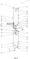
- Fig. 4 shows a side view of a wall cladding system 1.
- the wall cladding system 1 comprises two non-metal profiles 6, 7 and an aluminium profile 8.
- Each non-metal profile 6, 7 comprises a front side 10 and an opposite rear side 12, as well as a first side 14.
- a second side 16 is indicated with a broken line.
- the non-metal profiles 6, 7 comprise a rounding 24 and a bevel 28 where the front side 10 and the second side 16 meet.
- the non-metal profiles 6, 7 comprise a second rounding 40 and a second bevel 42 where the front side 10 and the first side 16 meet.
- the second rounding 40 and the second bevel 42 fulfill a similar function to the first rounding 24 and the first bevel 28.
- the second rounding 40 and the second bevel 42 guide a hot airflow which, in this example, flows from the non-metal profile 6 to the non-metal profile 7, while the first rounding 24 and the first bevel 28 guide a hot airflow which flows from the non-metal profile 7 to the non-metal profile 6.
- the fire reaction of the wall cladding system 1 is to a certain extent independent of the direction in which any fire spreads. This is especially relevant when the non-metal profiles are vertically positioned and a burning non-metal profile generates both on its first side 14 and on its second side 16 a hot airflow that can conduct heat to an adjacent non-metal profile. With horizontally placed non-metal profiles, this is different, since with horizontal profiles it may be expected that a hot airflow mainly leads heat to a non-metal profile located above.
- a part 14-1 of the first side 14 and a part 16-1 of the second side 16 that is between the front side 10 and the respective recess 18 and 19, is preferably relatively short, preferably not higher than 40 mm, more preferably approximately 10 mm, preferably approximately between 5% and 15% of the width B of the non-metal profile, more preferably approximately 10% of the width B of the non-metal profile.
- the height of the upstanding parts 14-1, 16-1 can be approximately 10 mm.
- exposure of the parts 14-1, 16-1 to a flame can be more limited, so that less heat development can take place and ignition will take place less fast. This is enhanced by providing the roundings 24, 40.
- the second rounding 40 has a radius R2 and the second bevel 42 has an angle H2.
- the preferred dimensions of the radius R2 and the angle H2 are the same as those of the radius R and the angle H of the first rounding 24 and the first bevel 28, though it should be noted that, for a same non-metal profile, the radius R of a first rounding 24 is not necessarily equal to the radius R2 of a second rounding 40, and that the angle H of a first bevel 28 is not necessarily equal to the angle H2 of a second bevel.
- the angle H2 or the radius R2, too is not necessarily equal for a plurality of non-metal profiles, but different non-metal profiles can have different angles H2 and/or radii R2.
- the second side 16 comprises furthermore a projecting portion 38.
- the projecting portion 38 as represented in Figure 4 is configured to be received between a first leg 20 and a third leg 30 of the aluminium profile 8.
- the distance A between the two non-metal profiles 6, 7 here is the distance between the projecting portion 38 of the non-metal profile 6 and the first side 14 of the non-metal profile 7.
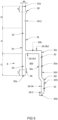
- Figure 5 shows a side view of a metal profile 8 according to the invention.
- the profile 8 extends in longitudinal direction in a direction transverse to the plane of the drawing (the paper).
- the metal, preferably aluminium, profile here comprises a first leg 20, a second leg 22 and a third leg 30.
- the first leg 20 and the second leg 22 are in line with each other, and a front side 8z forms one flat surface.
- the profile 8 is an extrusion profile.
- the third leg 30 is approximately parallel with the first leg 20, and extends beyond the first leg 20.
- the third leg 30 here has a first portion 30a which is parallel with the first leg 20, and a second portion 30b which connects the first portion 30a with the first leg 20.
- the first leg 20 and the second leg 22 are both provided with a projection 26, in particular the projection 26 is on a rear side 8t opposite to the front side 8z.
- the first leg 20 and the second leg 22 respectively has a projection 26, but more than one projection is also possible.
- the projections 26, or thickenings ensure that the first leg 20 and the second leg 22, respectively, can be clampingly received in corresponding recesses of the non-metal profiles 6, 7.
- the front side 8z of the first leg 20 and the second leg 22 can form a largest possible contact surface with a side of the recess of the non-metal profile.
- the contact surface between the metal profile and the non-metal profile is preferably as large as possible, and the heat of the non-metal profile can be abstracted by the metal profile which, certainly when implemented in aluminium, is a better heat conductor than the wood.
- penetration of the flame into the recesses can be counteracted.
- the flame remains on the outside and the combustible surface is not enlarged. The arising of double-sided burning-in can be counteracted.
- the right angles that have been formed by the provision of the recesses in the wood can be screened.
- the non-metal profile has no right, sharp, non-rounded angles anymore that are exposed to a flame.
- the angles 40, 24 of the non-metal profile that may be exposed to a flame have been rounded to promote heat spreading.
- the heat concentration is relatively large, so that relatively easily ignition arises on such non-rounded angles. This is counteracted by sufficiently rounding the angles which may be exposed to a flame.
- the projections 26 are at a distance x1, x2, respectively, from the ends 20a, 22a of the first leg 20 and the second leg 22.
- the distances x1 and x2 may be equal, but may also be different.
- the distance x1, x2 is approximately between 2 mm and 15 mm, more preferably the distance x1, x2 is approximately 5 mm.
- the non-metal profile may to some extent be slightly bent, the recesses provided therein may also be slightly deformed.
- the end 20a, 22a can relatively readily pilot itself into the recess, so as, when the thickening 26 enters the recess, to initiate clamping in order for the first leg 20 and the second leg 22, respectively, to be clampingly received in the corresponding recess.
- the first leg 20 is preferably completely received into the corresponding recess.
- the length 11 of the first leg 20 is approximately 10% of the width B of the non-metal profile 6, 7.
- the width B of the non-metal profile 6, 7 is indicated in Figure 1 , and, as already stated, can vary between different profiles.
- the thickness D of the non-metal profiles 6, 7 is also indicated in Figure 1 , and can also vary.
- the wood of the profiles 6, 7 warps, for one thing in the width direction, and also warps more than the aluminium of the metal profile 8. To be able to allow for this warp of the wood, an insertion pitch of about 10% of the width of the non-metal profile is recommended.
- the second leg 22 extends into the corresponding recess over a distance, 12, of about 10% of the width of the corresponding non-metal profile.
- the second leg 22 does not extend completely into the corresponding recess of the non-metal profile, so that between the first non-metal profile 6 and the second non-metal profile 7 a distance is created in which a part, lz, of the side 8z of the aluminium profile 8 is visible.
- the lengths 11, 12 can be equal, but can also be different, depending on the width of the corresponding non-metal profile.
- the profile 8 in side view has an h-shaped configuration. Between the first leg 20 and the third leg 30, the receiving cavity 300 is formed.
- The, after mounting, visible part lz of the aluminium profile 8 functions especially as a barrier to flame spread. To this end, it is also important that the side 8z makes contact with the corresponding recess in the non-metal profile over a largest possible surface, so that the front side 8z can function as a barrier, and the flame cannot get between or into the recess.
- the visible part lz of the aluminium profile 8 can make the flame proceed less fast from one non-metal profile 6 to a next non-metal profile 7. Thus, the flame spread, as well as the heat development, can be slowed up.
- the front side 8z ensures that the wall against which the wall cladding system is mounted, is screened from environmental influences, such as dirt, wind, rain, UV light, etc.
- the profile 8 is provided with at least one cut 29.
- the cut 29-2 in the second leg 22 can, on the one hand, accommodate expansion and/or shrinkage of the aluminium profile 8 to some extent. On the other, the cut can partly ensure that the second leg 22 is received in the corresponding recess of the non-metal profile in a properly clamping manner. For instance, if the recess were not entirely straight, on the one hand the thinner end 22a can function as a pilot, on the other hand the second leg 22 can yield slightly at the location of the cut in order to be received in the recess as well as possible to create optimal contact between the side 8z and the non-metal profiles.
- the depth of the cut 29-2 is preferably approximately 1/3 rd of the thickness dd of the aluminium profile 8.
- the leg 22 may be made to yield at the cut 29-2 so as to make the second leg 22 clamp better in the recess.
- the cut 29-2 can then rather be a yield line.
- the third leg 30, in particular the transverse section, being the second portion 30b, is here provided with two cuts 29-3b1, 29-3b2, opposite each other, and at a distance from each other. These cuts 29 can counteract unduly large deformations resulting from expansions and/or shrinkage of the aluminium profile. By providing two obliquely opposite cuts, deformations can be absorbed in the third leg, and the first and second leg can be more or less spared, so that the contact with the non-metal profile can be preserved, and hence also the screening from flame and/or environmental influences.
- the thickness dd of the aluminium profile 8, in particular the thickness dd of the first leg, and the second leg in line therewith, is preferably between approximately 2 mm and approximately 7 mm, more preferably approximately 5 mm.
- a relatively thick first and, in line therewith, second leg can provide, in case of fire, for a proper heat conduction between the non-metal profiles and the aluminium profile. Also, a relatively thick profile can absorb much heat before the profile will fail.
- a cut 29 is provided, cut 29-34.
- This cut has as its principal function to indicate a position where the fastener, screw 34, can be put in.
- the screw can be arranged in an optimal position, so that the screwhead can be received in the trough 32, and need not project beyond the front side 30c of the third leg 30, portion 30a.
- the rear side 32t of the trough 32 can abut against a framework 2, and a front side 30c of the third leg, portion 30a, can abut against a rear side of the non-metal profile.
- the third leg, at least, portion 30a is clamped between the non-metal profile and the framework 2.
- a rear side 30t of the third leg 30 and/or a rear side 32t of the trough 32 may be provided with a relief such as a ribbed or a corrugated or a toothed surface 303.
- a relief such as a ribbed or a corrugated or a toothed surface 303.
- the relief surface on the rear side 30t of the third leg 30 is advantageously disposed against the framework 2 disposed behind and/or in the cavity in between so that it can also be ventilated, which promotes the heat dissipation.
- a ribbed or toothed surface 303 is provided with vertical ribs, this allows, in case of vertical assembly, any intermediate moisture to be drained easily.
- the ribs, slots or grooves can then effectively serve as small drains. Moisture accumulates less fast and can be drained more simply, which can prolong the life span of the wall cladding system and/or the framework.
- the trough 32 is provided at the free end 30d of the third leg 30, portion 30a thereof.
- the trough 32 projects beyond the first leg 20, so that the screw 34 which is to be fitted through the trough is well accessible from a front side allowing it to be simply screwed in.
- the trough 32 is bounded on both sides by upstanding or oblique edges, as a consequence of which the screwhead can be completely received in the trough and can be enclosed therein.
- the screwhead after mounting, can be enclosed between the trough and the upstanding edges thereof and the non-metal profile. In this way, the screwhead can be protected from environmental influences, such as wind, dirt, water, but also from flame in case of fire.
- a cut 29 is provided, being cut 29-3.
- This cut 29 also ensures that warp of the non-metal profile can be accommodated in that the upstanding edge due to the cut 29 can yield so as to be able to move along with expansion and/or shrinkage of the non-metal profile.
- the wall cladding system can achieve a highly favorable fire reaction class.
- the metal profile is also configured such that on the one hand it can achieve a large contact surface with the non-metal profiles and on the other hand also leaves sufficient space to be able to accommodate expansion, shrinkage and deformation of the wood.
- the legs that extend into the non-metal profiles are sufficiently long to be able to continue to make contact also upon strong shrinkage.
- the wall cladding system as a roof cladding system, it can contribute to reduction of the combustible surface of a building, in that the wall cladding system forms a tight shell which screens an underlying wall, such as a roof, from environmental influences.
- the figures represent a vertical wall cladding. It will be clear, however, that a wall cladding can also be mounted on oblique or even horizontal surfaces. The word "facade” should therefore not be interpreted in a limited sense as being a vertical surface. Furthermore, it is noted that the wall cladding can be applied both inside and outside. The word wall cladding can therefore also be read as roof cladding, ceiling cladding, or facade cladding and can be attached to a building both exteriorly and interiorly.
- the non-metal profiles are described as beam-shaped. Because of the ratio between the different dimensions of the non-metal profiles, however, the non-metal profiles will mainly approximate a plank-shaped profile. It will be clear to a skilled person, however, that beam-shaped can also be read as plank-shaped.
Landscapes
- Engineering & Computer Science (AREA)
- Architecture (AREA)
- Civil Engineering (AREA)
- Structural Engineering (AREA)
- Finishing Walls (AREA)
- Building Environments (AREA)
- Load-Bearing And Curtain Walls (AREA)
Claims (20)
- Wandverkleidungssystem zur Befestigung an einer Fassadenwand, umfassend:mindestens zwei längliche Nichtmetallprofile (6, 7); undmindestens ein längliches Metallprofil (8);wobei jedes Nichtmetallprofil (6, 7) so für eine Verbindung mit dem mindestens einen Metallprofil (8) konfiguriert ist, dass, wenn die beiden Nichtmetallprofile (6, 7) mit einem gleichen Metallprofil (8) verbunden sind, sich die Nichtmetallprofile (6, 7) in einem Abstand zueinander mit dem Metallprofil (8) dazwischen befinden, und wobei die Nichtmetallprofile (6, 7) im Wesentlichen trägerförmige Profile sind, die eine Vorderseite (10) und eine gegenüberliegende Rückseite (12) in Längsrichtung des Nichtmetallprofils umfassen, sowie eine erste Seite (14) und eine gegenüberliegende zweite Seite (16), die sich in Längsrichtung zwischen der Vorderseite (10) und der Rückseite (12) erstrecken, wobei die erste und die zweite Seite (14, 16) für eine Verbindung mit dem Metallprofil (8) konfiguriert sind,wobei das Metallprofil (8) einen ersten Schenkel (20) und einen zweiten Schenkel (22) umfasst, die jeweils in eine entsprechende Ausnehmung in der ersten und der zweiten Seite (14, 16) der Nichtmetallprofile einsetzbar sind,und wobei das Metallprofil (8) ferner einen dritten Schenkel (30) umfasst, wobei der dritte Schenkel (30) etwa parallel zum ersten Schenkel (20) ist, sodass zwischen dem ersten Schenkel und dem dritten Schenkel ein Aufnahmehohlraum besteht, in den ein Teil eines Nichtmetallprofils (6, 7) aufgenommen werden kann, wobei der dritte Schenkel (30) des Metallprofils (8) eine Mulde (32) zur versenkten Aufnahme eines Befestigungselements zum Anbringen des Metallprofils an einer Fassadenwand umfasst, und wobei die Mulde (32) in den dritten Schenkel (30) relativ zu einer der Vorderseite (10) des Nichtmetallprofils (6, 7) zugewandten Seite des dritten Schenkels (30) eingelassen ist, sodass ein Kopf des Befestigungselements (34) in die Mulde (32) passt und sich nicht über einer Vorderseite (30c) des dritten Schenkels (30) erstreckt,dadurch gekennzeichnet, dass jeder von dem ersten Schenkel (20) und dem zweiten Schenkel (22) des Metallprofils einen Vorsprung (26) umfasst, sodass jeder von dem ersten Schenkel (20) und dem zweite Schenkel (22) in der entsprechenden Vertiefung der ersten Seite (14) beziehungsweise der zweiten Seite (16) der Nichtmetallprofile (6, 7) klemmbar aufnehmbar ist, und dadurch, dass der dritte Schenkel (30) einen ersten Abschnitt (30a) aufweist, der parallel zum ersten Schenkel (20) ist, und einen zweiten Abschnitt (30b), der den ersten Abschnitt (30a) mit dem ersten Schenkel (20) verbindet, und wobei der zweite Abschnitt (30b) mit zwei einander gegenüberliegenden und voneinander beabstandeten Einschnitten (29-3b1, 29-3b2) versehen ist.
- Wandverkleidungssystem nach Anspruch 1, wobei sich der Vorsprung (26) auf einer ersten Seite jedes von dem ersten Schenkel (20) und dem zweiten Schenkel (22) befindet, sodass eine zweite Seite jedes von dem ersten Schenkel (20) und dem zweiten Schenkel (22) gegenüber der ersten Seite eine Kontaktfläche mit einer Seite der entsprechenden Ausnehmung (18, 19) der jeweiligen Nichtmetallprofile (7, 6) bilden kann.
- Wandverkleidungssystem nach einem beliebigen der vorstehenden Ansprüche, wobei der Vorsprung (26) am ersten Schenkel (20) und der Vorsprung (26) am zweiten Schenkel (22) in einem Abstand von einem freien Ende (20a, 22a) des ersten Schenkels beziehungsweise des zweiten Schenkels (20, 22) liegen, vorzugsweise in einem Abstand von mehr als 3 mm, stärker bevorzugt mehr als 4 mm, stärker bevorzugt zwischen 4 mm und 15 mm.
- Wandverkleidungssystem nach einem beliebigen der vorstehenden Ansprüche, wobei der erste und der zweite Schenkel (20, 22) auf einer gemeinsamen Linie liegen, gemeinsam eine der Vorderseite (10) der Nichtmetallprofile (6, 7) zugewandte Seite bildend.
- Wandverkleidungssystem nach einem beliebigen der vorstehenden Ansprüche, wobei sich der dritte Schenkel (30) über den ersten Schenkel (20) hinaus erstreckt.
- Wandverkleidungssystem nach einem beliebigen der vorstehenden Ansprüche, wobei der dritte Schenkel (30) des Metallprofils (8) an die Rückseite des Nichtmetallprofils (6, 7) angrenzt, insbesondere wobei eine der Vorderseite (10) des Nichtmetallprofils (6, 7) zugewandte Seite des dritten Schenkels (30) eine Kontaktfläche mit der Rückseite (12) des Nichtmetallprofils (6, 7) bildet.
- Wandverkleidungssystem nach einem beliebigen der Ansprüche 1-6, wobei die Mulde (32) am freien Ende des dritten Schenkels (30) vorgesehen ist.
- Wandverkleidungssystem nach Anspruch 7, wobei zwischen einer freien hochstehenden Kante der Mulde und einer Einbettung der Mulde (32) ein Ausschnitt (29) vorgesehen ist, um Materialausdehnung und/oder - schrumpfung aufnehmen zu können.
- Wandverkleidungssystem nach einem beliebigen der vorstehenden Ansprüche, wobei das Metallprofil (8) mit mindestens einem Schnitt (29) in einer Dickenrichtung des betreffenden Schenkels des Metallprofils (8) versehen ist.
- Wandverkleidungssystem nach Anspruch 9, wobei die Tiefe des Schnitts (29) höchstens 10 % der Dicke des betreffenden Schenkels des Metallprofils (8) beträgt.
- Wandverkleidungssystem nach einem beliebigen der vorstehenden Ansprüche, wobei mindestens ein Übergang zwischen der Vorderseite (10) und der ersten Seite (14) und/oder zwischen der Vorderseite (10) und der zweiten Seite (16) und/oder zwischen der Rückseite (12) und der ersten Seite (14) und/oder zwischen der Rückseite (12) und der zweiten Seite (16) des Nichtmetallprofils (6, 7) abgeschrägt und/oder abgerundet ist, wobei die Abrundung einen Radius zwischen 1 und 10 mm, vorzugsweise zwischen 2 und 5 mm, stärker bevorzugt 3 mm, aufweist.
- Wandverkleidungssystem nach Anspruch 11, wobei mindestens ein Übergang zwischen der Vorderseite (10) und der ersten Seite (14) und/oder zwischen der Vorderseite (10) und der zweiten Seite (16) und/oder zwischen der Rückseite (12) und der ersten Seite (14) und/oder zwischen der Rückseite (12) und der zweiten Seite (16) abgeschrägt und/oder abgerundet ist.
- Wandverkleidungssystem nach einem beliebigen der vorstehenden Ansprüche 11-12, wobei die Abschrägung einen Winkel zwischen 25 und 60 Grad, vorzugsweise zwischen 30 und 50 Grad, stärker bevorzugt etwa 45 Grad, aufweist.
- Wandverkleidungssystem nach einem beliebigen der vorstehenden Ansprüche, wobei die Nichtmetallprofile (6, 7) unbehandelte Nichtmetallprofile sind.
- Wandverkleidungssystem nach einem beliebigen der vorstehenden Ansprüche, wobei das Metallprofil ein Metallprofil (8) ist, wobei das Metallprofil vorzugsweise ein Aluminiumprofil ist.
- Wandverkleidungssystem nach Anspruch 15, wobei das Metallprofil (8) mit einer Beschichtung versehen ist.
- Wandverkleidungssystem nach einem beliebigen der vorstehenden Ansprüche, wobei jedes der mindestens zwei Nichtmetallprofile (6, 7) auf der der Seite mit der Ausnehmung gegenüberliegenden Seite eine zweite Ausnehmung zum Aufnehmen mindestens eines Teils eines zweiten Metallprofils (8) umfasst.
- Wandverkleidungssystem nach einem beliebigen der vorstehenden Ansprüche 1-17, wobei jedes der mindestens zwei Nichtmetallprofile (6, 7) auf der der Seite mit der Ausnehmung (19, 18) gegenüberliegenden Seite einen vorstehenden Abschnitt umfasst, dazu konfiguriert, von einem Teil des Metallprofils (8) aufgenommen zu werden, insbesondere in dem Aufnahmehohlraum zwischen dem ersten Schenkel (20) und dem dritten Schenkel (30) aufgenommen zu werden.
- Wandverkleidungssystem nach einem beliebigen der vorstehenden Ansprüche, wobei jedes der mindestens zwei Nichtmetallprofile (6, 7) mit einem sich von der ersten und/oder der zweiten Seite (14, 16) erstreckenden Flansch (36) versehen ist, wobei durch den Flansch (36) ein Befestigungselement zur Befestigung an der Fassadenwand aufnehmbar ist, wobei das Befestigungselement vorzugsweise schräg durch einen Übergang zwischen dem Flansch und der zugehörigen ersten und/oder zweiten Seite aufnehmbar ist.
- Wandverkleidungssystem nach einem beliebigen der vorstehenden Ansprüche, umfassend eine Vielzahl von Nichtmetallprofilen (6, 7) und eine Vielzahl von Metallprofilen (8), wobei jedes Nichtmetallprofil (6, 7) für eine Verbindung mit zwei Metallprofilen (8) konfiguriert ist, und wobei jedes Metallprofil (8) für eine Verbindung mit zwei Nichtmetallprofilen (6, 7) konfiguriert ist, um ein System mit nacheinander einem Nichtmetallprofil und einem Metallprofil zu erhalten.
Priority Applications (1)
| Application Number | Priority Date | Filing Date | Title |
|---|---|---|---|
| EP24198443.4A EP4467745A3 (de) | 2020-11-25 | 2021-11-24 | Wandverkleidungssystem |
Applications Claiming Priority (2)
| Application Number | Priority Date | Filing Date | Title |
|---|---|---|---|
| NL2026984A NL2026984B1 (nl) | 2020-11-25 | 2020-11-25 | Wandbekledingssysteem |
| BE20205850A BE1028822B1 (nl) | 2020-11-25 | 2020-11-25 | Wandbekledingssysteem |
Related Child Applications (2)
| Application Number | Title | Priority Date | Filing Date |
|---|---|---|---|
| EP24198443.4A Division-Into EP4467745A3 (de) | 2020-11-25 | 2021-11-24 | Wandverkleidungssystem |
| EP24198443.4A Division EP4467745A3 (de) | 2020-11-25 | 2021-11-24 | Wandverkleidungssystem |
Publications (2)
| Publication Number | Publication Date |
|---|---|
| EP4050178A1 EP4050178A1 (de) | 2022-08-31 |
| EP4050178B1 true EP4050178B1 (de) | 2025-02-12 |
Family
ID=82595773
Family Applications (2)
| Application Number | Title | Priority Date | Filing Date |
|---|---|---|---|
| EP21210252.9A Active EP4050178B1 (de) | 2020-11-25 | 2021-11-24 | Wandverkleidungssystem |
| EP24198443.4A Pending EP4467745A3 (de) | 2020-11-25 | 2021-11-24 | Wandverkleidungssystem |
Family Applications After (1)
| Application Number | Title | Priority Date | Filing Date |
|---|---|---|---|
| EP24198443.4A Pending EP4467745A3 (de) | 2020-11-25 | 2021-11-24 | Wandverkleidungssystem |
Country Status (4)
| Country | Link |
|---|---|
| EP (2) | EP4050178B1 (de) |
| DK (1) | DK4050178T3 (de) |
| LT (1) | LT4050178T (de) |
| PL (1) | PL4050178T3 (de) |
Families Citing this family (2)
| Publication number | Priority date | Publication date | Assignee | Title |
|---|---|---|---|---|
| NL2036017B1 (en) | 2023-10-12 | 2025-04-30 | Paulussen Houthandel B V | Metal corner profile for a wall cladding system |
| NL2037610B1 (en) * | 2024-05-03 | 2025-11-18 | Paulussen Houthandel B V | Outdoor flooring System |
Family Cites Families (8)
| Publication number | Priority date | Publication date | Assignee | Title |
|---|---|---|---|---|
| US1888611A (en) * | 1930-06-10 | 1932-11-22 | Concrete Wood Floor Clip Compa | Flooring and the like |
| FR2433087A1 (fr) * | 1978-08-07 | 1980-03-07 | Safama | Dispositif pour fixer sur une structure murale, et a distance de celle-ci, un revetement constitue d'une pluralite de panneaux |
| FI874556A7 (fi) | 1987-10-16 | 1989-04-17 | Lohja Ab Oy | Foerfarande foer ytbelaeggning av vaeggar och daervid anvaent elementsystem. |
| CH693510A5 (de) * | 2003-04-09 | 2003-09-15 | Werner Aeschlimann | Sichttäfer mit Einlegefedern. |
| GB2495475A (en) * | 2011-10-03 | 2013-04-17 | Hardie James Technology Ltd | Non combustible flooring comprising decking components and intermediate joining members |
| US8984838B2 (en) * | 2011-11-09 | 2015-03-24 | Robert B. Bordener | Kit and assembly for compensating for coefficients of thermal expansion of decorative mounted panels |
| DE202017106824U1 (de) * | 2017-11-09 | 2017-12-12 | Hilmar Grünberger | Fassadenverkleidung zum Verkleiden einer Wand oder Gebäudefassade |
| BE1026656B1 (nl) | 2019-03-19 | 2020-04-22 | Houtmagazijn Verdonckt Nv | Bevestigingsprofiel, lamellen en samenstelling van voorgaande |
-
2021
- 2021-11-24 PL PL21210252.9T patent/PL4050178T3/pl unknown
- 2021-11-24 EP EP21210252.9A patent/EP4050178B1/de active Active
- 2021-11-24 DK DK21210252.9T patent/DK4050178T3/da active
- 2021-11-24 LT LTEP21210252.9T patent/LT4050178T/lt unknown
- 2021-11-24 EP EP24198443.4A patent/EP4467745A3/de active Pending
Also Published As
| Publication number | Publication date |
|---|---|
| LT4050178T (lt) | 2025-05-26 |
| EP4467745A2 (de) | 2024-11-27 |
| EP4467745A3 (de) | 2025-02-26 |
| EP4050178A1 (de) | 2022-08-31 |
| PL4050178T3 (pl) | 2025-05-05 |
| DK4050178T3 (da) | 2025-04-14 |
Similar Documents
| Publication | Publication Date | Title |
|---|---|---|
| US10400456B2 (en) | Polymer-based bracket system for exterior cladding | |
| US10221574B2 (en) | Insulting structure for buildings | |
| EP4050178B1 (de) | Wandverkleidungssystem | |
| US6374561B1 (en) | External wall panel construction | |
| CN110259351B (zh) | 一种高效节能的铝合金防火窗的制造工艺 | |
| US4432181A (en) | Wall construction for architectural structure | |
| JP6396174B2 (ja) | 建具 | |
| JP2010180546A (ja) | 外装材 | |
| CN217871385U (zh) | 一种水泥纤维板边框与光伏玻璃一体形成的外挂墙板 | |
| EP4600432A2 (de) | Belüftetes fassadenverkleidungssystem | |
| JP4843365B2 (ja) | 軒天井板の支持構造 | |
| JPH07252928A (ja) | 縦目地構造 | |
| CN212836157U (zh) | 一种适用于大跨度工程的幕墙节点连接结构 | |
| JP2766221B2 (ja) | カーテンウォール | |
| BE1028822B1 (nl) | Wandbekledingssysteem | |
| CN216195604U (zh) | 一种可基于锚杆固定的外墙防火保温板 | |
| NL2026984B1 (nl) | Wandbekledingssysteem | |
| CN2179414Y (zh) | 可锁组多层屋顶浪板用支承架 | |
| US12077960B2 (en) | Stucco construction system | |
| JPH0347361A (ja) | 壁耐火目地構造 | |
| EP4502312A1 (de) | Grundprofil zur befestigung von fassadenverkleidungen an gedämmten und/oder hinterlüfteten fassaden | |
| US12078007B2 (en) | Method of installing a window and composite window bracket | |
| CN215167092U (zh) | 一种轻钢龙骨石膏板防火吊顶 | |
| JP5010361B2 (ja) | 大型壁パネルの設置構造 | |
| JP7161902B2 (ja) | 軒天構造及び軒先側支持部材 |
Legal Events
| Date | Code | Title | Description |
|---|---|---|---|
| PUAI | Public reference made under article 153(3) epc to a published international application that has entered the european phase |
Free format text: ORIGINAL CODE: 0009012 |
|
| STAA | Information on the status of an ep patent application or granted ep patent |
Free format text: STATUS: THE APPLICATION HAS BEEN PUBLISHED |
|
| AK | Designated contracting states |
Kind code of ref document: A1 Designated state(s): AL AT BE BG CH CY CZ DE DK EE ES FI FR GB GR HR HU IE IS IT LI LT LU LV MC MK MT NL NO PL PT RO RS SE SI SK SM TR |
|
| STAA | Information on the status of an ep patent application or granted ep patent |
Free format text: STATUS: REQUEST FOR EXAMINATION WAS MADE |
|
| 17P | Request for examination filed |
Effective date: 20230210 |
|
| RBV | Designated contracting states (corrected) |
Designated state(s): AL AT BE BG CH CY CZ DE DK EE ES FI FR GB GR HR HU IE IS IT LI LT LU LV MC MK MT NL NO PL PT RO RS SE SI SK SM TR |
|
| STAA | Information on the status of an ep patent application or granted ep patent |
Free format text: STATUS: EXAMINATION IS IN PROGRESS |
|
| 17Q | First examination report despatched |
Effective date: 20230710 |
|
| GRAP | Despatch of communication of intention to grant a patent |
Free format text: ORIGINAL CODE: EPIDOSNIGR1 |
|
| STAA | Information on the status of an ep patent application or granted ep patent |
Free format text: STATUS: GRANT OF PATENT IS INTENDED |
|
| INTG | Intention to grant announced |
Effective date: 20231213 |
|
| GRAJ | Information related to disapproval of communication of intention to grant by the applicant or resumption of examination proceedings by the epo deleted |
Free format text: ORIGINAL CODE: EPIDOSDIGR1 |
|
| STAA | Information on the status of an ep patent application or granted ep patent |
Free format text: STATUS: EXAMINATION IS IN PROGRESS |
|
| GRAP | Despatch of communication of intention to grant a patent |
Free format text: ORIGINAL CODE: EPIDOSNIGR1 |
|
| STAA | Information on the status of an ep patent application or granted ep patent |
Free format text: STATUS: GRANT OF PATENT IS INTENDED |
|
| INTC | Intention to grant announced (deleted) | ||
| INTG | Intention to grant announced |
Effective date: 20240503 |
|
| GRAJ | Information related to disapproval of communication of intention to grant by the applicant or resumption of examination proceedings by the epo deleted |
Free format text: ORIGINAL CODE: EPIDOSDIGR1 |
|
| STAA | Information on the status of an ep patent application or granted ep patent |
Free format text: STATUS: EXAMINATION IS IN PROGRESS |
|
| GRAS | Grant fee paid |
Free format text: ORIGINAL CODE: EPIDOSNIGR3 |
|
| STAA | Information on the status of an ep patent application or granted ep patent |
Free format text: STATUS: GRANT OF PATENT IS INTENDED |
|
| GRAP | Despatch of communication of intention to grant a patent |
Free format text: ORIGINAL CODE: EPIDOSNIGR1 |
|
| INTC | Intention to grant announced (deleted) | ||
| INTG | Intention to grant announced |
Effective date: 20240924 |
|
| GRAA | (expected) grant |
Free format text: ORIGINAL CODE: 0009210 |
|
| STAA | Information on the status of an ep patent application or granted ep patent |
Free format text: STATUS: THE PATENT HAS BEEN GRANTED |
|
| AK | Designated contracting states |
Kind code of ref document: B1 Designated state(s): AL AT BE BG CH CY CZ DE DK EE ES FI FR GB GR HR HU IE IS IT LI LT LU LV MC MK MT NL NO PL PT RO RS SE SI SK SM TR |
|
| REG | Reference to a national code |
Ref country code: GB Ref legal event code: FG4D |
|
| REG | Reference to a national code |
Ref country code: CH Ref legal event code: EP |
|
| REG | Reference to a national code |
Ref country code: DE Ref legal event code: R096 Ref document number: 602021025934 Country of ref document: DE |
|
| REG | Reference to a national code |
Ref country code: IE Ref legal event code: FG4D |
|
| P01 | Opt-out of the competence of the unified patent court (upc) registered |
Free format text: CASE NUMBER: APP_8254/2025 Effective date: 20250218 |
|
| REG | Reference to a national code |
Ref country code: DK Ref legal event code: T3 Effective date: 20250410 |
|
| REG | Reference to a national code |
Ref country code: NL Ref legal event code: FP |
|
| PG25 | Lapsed in a contracting state [announced via postgrant information from national office to epo] |
Ref country code: RS Free format text: LAPSE BECAUSE OF FAILURE TO SUBMIT A TRANSLATION OF THE DESCRIPTION OR TO PAY THE FEE WITHIN THE PRESCRIBED TIME-LIMIT Effective date: 20250512 |
|
| PG25 | Lapsed in a contracting state [announced via postgrant information from national office to epo] |
Ref country code: FI Free format text: LAPSE BECAUSE OF FAILURE TO SUBMIT A TRANSLATION OF THE DESCRIPTION OR TO PAY THE FEE WITHIN THE PRESCRIBED TIME-LIMIT Effective date: 20250212 |
|
| PG25 | Lapsed in a contracting state [announced via postgrant information from national office to epo] |
Ref country code: ES Free format text: LAPSE BECAUSE OF FAILURE TO SUBMIT A TRANSLATION OF THE DESCRIPTION OR TO PAY THE FEE WITHIN THE PRESCRIBED TIME-LIMIT Effective date: 20250212 |
|
| PG25 | Lapsed in a contracting state [announced via postgrant information from national office to epo] |
Ref country code: NO Free format text: LAPSE BECAUSE OF FAILURE TO SUBMIT A TRANSLATION OF THE DESCRIPTION OR TO PAY THE FEE WITHIN THE PRESCRIBED TIME-LIMIT Effective date: 20250512 Ref country code: IS Free format text: LAPSE BECAUSE OF FAILURE TO SUBMIT A TRANSLATION OF THE DESCRIPTION OR TO PAY THE FEE WITHIN THE PRESCRIBED TIME-LIMIT Effective date: 20250612 |
|
| PG25 | Lapsed in a contracting state [announced via postgrant information from national office to epo] |
Ref country code: HR Free format text: LAPSE BECAUSE OF FAILURE TO SUBMIT A TRANSLATION OF THE DESCRIPTION OR TO PAY THE FEE WITHIN THE PRESCRIBED TIME-LIMIT Effective date: 20250212 |
|
| PG25 | Lapsed in a contracting state [announced via postgrant information from national office to epo] |
Ref country code: LV Free format text: LAPSE BECAUSE OF FAILURE TO SUBMIT A TRANSLATION OF THE DESCRIPTION OR TO PAY THE FEE WITHIN THE PRESCRIBED TIME-LIMIT Effective date: 20250212 Ref country code: PT Free format text: LAPSE BECAUSE OF FAILURE TO SUBMIT A TRANSLATION OF THE DESCRIPTION OR TO PAY THE FEE WITHIN THE PRESCRIBED TIME-LIMIT Effective date: 20250612 |
|
| PG25 | Lapsed in a contracting state [announced via postgrant information from national office to epo] |
Ref country code: GR Free format text: LAPSE BECAUSE OF FAILURE TO SUBMIT A TRANSLATION OF THE DESCRIPTION OR TO PAY THE FEE WITHIN THE PRESCRIBED TIME-LIMIT Effective date: 20250513 Ref country code: BG Free format text: LAPSE BECAUSE OF FAILURE TO SUBMIT A TRANSLATION OF THE DESCRIPTION OR TO PAY THE FEE WITHIN THE PRESCRIBED TIME-LIMIT Effective date: 20250212 |
|
| REG | Reference to a national code |
Ref country code: AT Ref legal event code: MK05 Ref document number: 1766164 Country of ref document: AT Kind code of ref document: T Effective date: 20250212 |
|
| PG25 | Lapsed in a contracting state [announced via postgrant information from national office to epo] |
Ref country code: SE Free format text: LAPSE BECAUSE OF FAILURE TO SUBMIT A TRANSLATION OF THE DESCRIPTION OR TO PAY THE FEE WITHIN THE PRESCRIBED TIME-LIMIT Effective date: 20250212 |
|
| PG25 | Lapsed in a contracting state [announced via postgrant information from national office to epo] |
Ref country code: SM Free format text: LAPSE BECAUSE OF FAILURE TO SUBMIT A TRANSLATION OF THE DESCRIPTION OR TO PAY THE FEE WITHIN THE PRESCRIBED TIME-LIMIT Effective date: 20250212 |
|
| PG25 | Lapsed in a contracting state [announced via postgrant information from national office to epo] |
Ref country code: IT Free format text: LAPSE BECAUSE OF FAILURE TO SUBMIT A TRANSLATION OF THE DESCRIPTION OR TO PAY THE FEE WITHIN THE PRESCRIBED TIME-LIMIT Effective date: 20250212 |
|
| PG25 | Lapsed in a contracting state [announced via postgrant information from national office to epo] |
Ref country code: AT Free format text: LAPSE BECAUSE OF FAILURE TO SUBMIT A TRANSLATION OF THE DESCRIPTION OR TO PAY THE FEE WITHIN THE PRESCRIBED TIME-LIMIT Effective date: 20250212 |
|
| PG25 | Lapsed in a contracting state [announced via postgrant information from national office to epo] |
Ref country code: CZ Free format text: LAPSE BECAUSE OF FAILURE TO SUBMIT A TRANSLATION OF THE DESCRIPTION OR TO PAY THE FEE WITHIN THE PRESCRIBED TIME-LIMIT Effective date: 20250212 Ref country code: EE Free format text: LAPSE BECAUSE OF FAILURE TO SUBMIT A TRANSLATION OF THE DESCRIPTION OR TO PAY THE FEE WITHIN THE PRESCRIBED TIME-LIMIT Effective date: 20250212 |
|
| PG25 | Lapsed in a contracting state [announced via postgrant information from national office to epo] |
Ref country code: RO Free format text: LAPSE BECAUSE OF FAILURE TO SUBMIT A TRANSLATION OF THE DESCRIPTION OR TO PAY THE FEE WITHIN THE PRESCRIBED TIME-LIMIT Effective date: 20250212 |
|
| PG25 | Lapsed in a contracting state [announced via postgrant information from national office to epo] |
Ref country code: SK Free format text: LAPSE BECAUSE OF FAILURE TO SUBMIT A TRANSLATION OF THE DESCRIPTION OR TO PAY THE FEE WITHIN THE PRESCRIBED TIME-LIMIT Effective date: 20250212 |
|
| REG | Reference to a national code |
Ref country code: DE Ref legal event code: R097 Ref document number: 602021025934 Country of ref document: DE |
|
| REG | Reference to a national code |
Ref country code: CH Ref legal event code: U11 Free format text: ST27 STATUS EVENT CODE: U-0-0-U10-U11 (AS PROVIDED BY THE NATIONAL OFFICE) Effective date: 20251201 |
|
| PGFP | Annual fee paid to national office [announced via postgrant information from national office to epo] |
Ref country code: LU Payment date: 20251119 Year of fee payment: 5 Ref country code: NL Payment date: 20251119 Year of fee payment: 5 |
|
| PLBE | No opposition filed within time limit |
Free format text: ORIGINAL CODE: 0009261 |
|
| STAA | Information on the status of an ep patent application or granted ep patent |
Free format text: STATUS: NO OPPOSITION FILED WITHIN TIME LIMIT |
|
| PGFP | Annual fee paid to national office [announced via postgrant information from national office to epo] |
Ref country code: DE Payment date: 20251119 Year of fee payment: 5 |
|
| PGFP | Annual fee paid to national office [announced via postgrant information from national office to epo] |
Ref country code: LT Payment date: 20251027 Year of fee payment: 5 Ref country code: GB Payment date: 20251121 Year of fee payment: 5 |
|
| PGFP | Annual fee paid to national office [announced via postgrant information from national office to epo] |
Ref country code: DK Payment date: 20251125 Year of fee payment: 5 |
|
| PGFP | Annual fee paid to national office [announced via postgrant information from national office to epo] |
Ref country code: FR Payment date: 20251126 Year of fee payment: 5 |
|
| PGFP | Annual fee paid to national office [announced via postgrant information from national office to epo] |
Ref country code: BE Payment date: 20251119 Year of fee payment: 5 |
|
| PGFP | Annual fee paid to national office [announced via postgrant information from national office to epo] |
Ref country code: CH Payment date: 20251201 Year of fee payment: 5 |
|
| 26N | No opposition filed |
Effective date: 20251113 |
|
| PGFP | Annual fee paid to national office [announced via postgrant information from national office to epo] |
Ref country code: PL Payment date: 20251022 Year of fee payment: 5 |