EP4050400B1 - Appareils et procédés d'affichage intégrant un masquage d'images - Google Patents
Appareils et procédés d'affichage intégrant un masquage d'images Download PDFInfo
- Publication number
- EP4050400B1 EP4050400B1 EP22152269.1A EP22152269A EP4050400B1 EP 4050400 B1 EP4050400 B1 EP 4050400B1 EP 22152269 A EP22152269 A EP 22152269A EP 4050400 B1 EP4050400 B1 EP 4050400B1
- Authority
- EP
- European Patent Office
- Prior art keywords
- image
- head
- real
- user
- world environment
- Prior art date
- Legal status (The legal status is an assumption and is not a legal conclusion. Google has not performed a legal analysis and makes no representation as to the accuracy of the status listed.)
- Active
Links
Images


Classifications
-
- G—PHYSICS
- G06—COMPUTING OR CALCULATING; COUNTING
- G06T—IMAGE DATA PROCESSING OR GENERATION, IN GENERAL
- G06T19/00—Manipulating three-dimensional [3D] models or images for computer graphics
- G06T19/006—Mixed reality
-
- G—PHYSICS
- G06—COMPUTING OR CALCULATING; COUNTING
- G06F—ELECTRIC DIGITAL DATA PROCESSING
- G06F3/00—Input arrangements for transferring data to be processed into a form capable of being handled by the computer; Output arrangements for transferring data from processing unit to output unit, e.g. interface arrangements
- G06F3/01—Input arrangements or combined input and output arrangements for interaction between user and computer
- G06F3/011—Arrangements for interaction with the human body, e.g. for user immersion in virtual reality
- G06F3/012—Head tracking input arrangements
-
- G—PHYSICS
- G06—COMPUTING OR CALCULATING; COUNTING
- G06T—IMAGE DATA PROCESSING OR GENERATION, IN GENERAL
- G06T15/00—Three-dimensional [3D] image rendering
- G06T15/50—Lighting effects
- G06T15/506—Illumination models
-
- G—PHYSICS
- G06—COMPUTING OR CALCULATING; COUNTING
- G06T—IMAGE DATA PROCESSING OR GENERATION, IN GENERAL
- G06T17/00—Three-dimensional [3D] modelling for computer graphics
-
- G—PHYSICS
- G06—COMPUTING OR CALCULATING; COUNTING
- G06T—IMAGE DATA PROCESSING OR GENERATION, IN GENERAL
- G06T7/00—Image analysis
- G06T7/50—Depth or shape recovery
-
- G—PHYSICS
- G06—COMPUTING OR CALCULATING; COUNTING
- G06T—IMAGE DATA PROCESSING OR GENERATION, IN GENERAL
- G06T7/00—Image analysis
- G06T7/70—Determining position or orientation of objects or cameras
-
- G—PHYSICS
- G06—COMPUTING OR CALCULATING; COUNTING
- G06T—IMAGE DATA PROCESSING OR GENERATION, IN GENERAL
- G06T7/00—Image analysis
- G06T7/70—Determining position or orientation of objects or cameras
- G06T7/73—Determining position or orientation of objects or cameras using feature-based methods
-
- G—PHYSICS
- G02—OPTICS
- G02B—OPTICAL ELEMENTS, SYSTEMS OR APPARATUS
- G02B27/00—Optical systems or apparatus not provided for by any of the groups G02B1/00 - G02B26/00, G02B30/00
- G02B27/01—Head-up displays
- G02B27/0101—Head-up displays characterised by optical features
- G02B2027/014—Head-up displays characterised by optical features comprising information/image processing systems
-
- G—PHYSICS
- G02—OPTICS
- G02B—OPTICAL ELEMENTS, SYSTEMS OR APPARATUS
- G02B27/00—Optical systems or apparatus not provided for by any of the groups G02B1/00 - G02B26/00, G02B30/00
- G02B27/0093—Optical systems or apparatus not provided for by any of the groups G02B1/00 - G02B26/00, G02B30/00 with means for monitoring data relating to the user, e.g. head-tracking, eye-tracking
-
- G—PHYSICS
- G06—COMPUTING OR CALCULATING; COUNTING
- G06T—IMAGE DATA PROCESSING OR GENERATION, IN GENERAL
- G06T2207/00—Indexing scheme for image analysis or image enhancement
- G06T2207/10—Image acquisition modality
- G06T2207/10028—Range image; Depth image; 3D point clouds
-
- G—PHYSICS
- G06—COMPUTING OR CALCULATING; COUNTING
- G06T—IMAGE DATA PROCESSING OR GENERATION, IN GENERAL
- G06T2207/00—Indexing scheme for image analysis or image enhancement
- G06T2207/30—Subject of image; Context of image processing
- G06T2207/30196—Human being; Person
- G06T2207/30201—Face
-
- G—PHYSICS
- G06—COMPUTING OR CALCULATING; COUNTING
- G06T—IMAGE DATA PROCESSING OR GENERATION, IN GENERAL
- G06T2215/00—Indexing scheme for image rendering
- G06T2215/12—Shadow map, environment map
Definitions
- the present disclosure relates to display apparatuses. Moreover, the present disclosure relates to methods of displaying that are implemented by such display apparatuses.
- Immersive extended-reality (XR) technologies such as virtual-reality (VR), augmented-reality (AR), mixed-reality (MR), and the like, are increasingly being employed nowadays in various fields such as entertainment, real estate, training, medical imaging operations, simulators, navigation, and the like.
- immersive XR technologies create immersive XR environments.
- a user of an XR device wears the XR device on his/her head to experience an XR environment.
- the user is present in a real-world environment which may, for example, be an indoor environment or an outdoor environment.
- the real-world environment includes real objects present therein.
- the virtual content is computer-generated content.
- an imaging system for producing mixed-reality images for a display apparatus.
- the imaging system includes a camera and a processor communicably coupled to the camera.
- the processor is configured to control the camera to capture an image of a real-world environment; analyze the image to identify a surface that displays visual content; compare the visual content displayed in the image with a reference image of the visual content to determine a size, a position and an orientation of the surface with respect to the camera; process the reference image of the visual content to generate a processed image of the visual content; and replace the visual content displayed in the image with the processed image to generate a mixed-reality image, wherein a resolution of the processed image is higher than a resolution of the visual content displayed in the image.
- a method for generating an image includes receiving a first image including color data and depth data, determining a viewpoint associated with an augmented reality (AR) and/or virtual reality (VR) display displaying a second image, receiving at least one calibration image including an object in the first image, the object being in a different pose as compared to a pose of the object in the first image, and generating the second image based on the first image, the viewpoint and the at least one calibration image.
- AR augmented reality
- VR virtual reality
- an image display apparatus for converting an image into a virtual viewpoint image so that the image of an object is not distorted.
- a background image is retrieved from an image;
- a virtual object model is extracted from the image and the background image;
- an object three-dimensional model is generated from the virtual object model;
- viewpoint conversion is performed on the background image and on the object three-dimensional model; the background image and the object three-dimensional model that have been viewpoint-converted are combined.
- the present disclosure seeks to provide a display apparatus.
- the present disclosure also seeks to provide a method of displaying that is implemented by such a display apparatus.
- An aim of the present disclosure is to provide a solution that overcomes at least partially the problems encountered in prior art.
- an embodiment of the present disclosure provides a display apparatus comprising:
- an embodiment of the present disclosure provides a method of displaying, the method being implemented by a display apparatus comprising at least one light source, at least one camera, head-tracking means, and at least one processor, the method comprising:
- Embodiments of the present disclosure substantially eliminate or at least partially address the aforementioned problems in the prior art, and enable presentation of realistic (namely, natural-looking) mixed-reality images for presentation of immersive mixed-reality environments.
- an underlined number is employed to represent an item over which the underlined number is positioned or an item to which the underlined number is adjacent.
- a non-underlined number relates to an item identified by a line linking the non-underlined number to the item. When a number is non-underlined and accompanied by an associated arrow, the non-underlined number is used to identify a general item at which the arrow is pointing.
- an embodiment of the present disclosure provides a display apparatus comprising:
- an embodiment of the present disclosure provides a method of displaying, the method being implemented by a display apparatus comprising at least one light source, at least one camera, head-tracking means, and at least one processor, the method comprising:
- the present disclosure provides the aforementioned display apparatus and the aforementioned method of displaying.
- the display apparatus presents realistic mixed-reality (MR) images to a user of the display apparatus.
- MR mixed-reality
- 3D three-dimensional
- the given image of the real-world environment to detect the at least one object present in the real-world environment, and embedding the at least one object in the intermediate MR image
- natural-looking MR images are generated for displaying. This improves immersiveness in MR environments and enhances a viewing experience for the user using the display apparatus.
- real and virtual parts of the MR images are occluded realistically to provide this enhanced viewing experience.
- display apparatus refers to a display system that is configured to present a mixed-reality (MR) environment to the user when the display apparatus in operation is used by the user.
- MR mixed-reality
- the display apparatus is implemented as a head-mounted device (HMD) and a computer coupled to the HMD.
- the HMD comprises the at least one light source, the at least one camera, and the head-tracking means
- the computer comprises the at least one processor. Therefore, computational tasks pertaining to presentation of the MR environment are entirely performed at the computer, by the at least one processor.
- the HMD comprises the at least one light source, the at least one camera, and the head-tracking means, and the at least one processor is implemented at both the HMD and the computer. Therefore, computational tasks pertaining to presentation of the MR environment are performed in a shared manner at both the HMD and the computer, by the at least one processor.
- the computer may be coupled to the HMD wirelessly and/or in a wired manner. Examples of the computer include, but are not limited to, a desktop computer, a laptop computer, a tablet computer, a workstation, and an MR console.
- the display apparatus is implemented as an HMD.
- the HMD comprises the at least one light source, the at least one camera, and the head-tracking means, and the at least one processor. Therefore, computational tasks pertaining to presentation of the MR environment are entirely performed at the HMD, by the at least one processor.
- the HMD is worn by the user on his/her head.
- the HMD is implemented, for example, as an MR headset, a pair of MR glasses, and the like, that is operable to display a visual scene of the MR environment to the user.
- the term "light source" refers to an element from which light emanates.
- a given light source is implemented as a display.
- a given MR image is displayed at the given light source.
- the display include, but are not limited to, a Liquid Crystal Display (LCD), a Light-Emitting Diode (LED)-based display, an Organic LED (OLED)-based display, a micro OLED-based display, an Active Matrix OLED (AMOLED)-based display, and a Liquid Crystal on Silicon (LCoS)-based display.
- a given light source is implemented as a projector.
- a given MR image is projected onto a projection screen or directly onto a retina of the user's eyes.
- the projector include, but are not limited to, an LCD-based projector, an LED-based projector, an OLED-based projector, an LCoS-based projector, a Digital Light Processing (DLP)-based projector, and a laser projector.
- DLP Digital Light Processing
- a given light source could be a multi-resolution light source, or a single-resolution light source.
- Multi-resolution light sources are configured to display images at two or more resolutions, whereas single-resolution light sources are configured to display images at a single resolution only.
- the display apparatus comprises one light source per eye, wherein each light source is a multi-resolution light source.
- the display apparatus comprises at least two light sources per eye, the at least two light sources comprising at least one first light source and at least one second light source, wherein the at least one first light source is configured to display first MR images at a first resolution and the at least one second light source is configured to display second MR images at a second resolution, the second resolution being higher than the first resolution.
- the term " camera" refers to an equipment that is operable to detect and process signals received from the real-world environment, so as to capture the given image of the real-world environment. These signals could be light waves, sound signals, or similar.
- the at least one camera is implemented as at least one of: a visible light camera, a depth camera. Examples of the visible light camera include, but are not limited to, a Red-Green-Blue-Depth (RGB), monochrome camera.
- RGB Red-Green-Blue-Depth
- the depth camera examples include, but are not limited to, a Red-Green-Blue-Depth (RGB-D) camera, a ranging camera, a Light Detection and Ranging (LiDAR) camera, a flash LiDAR camera, a Time-of-Flight (ToF) camera, a Sound Navigation and Ranging (SONAR) camera, a laser rangefinder, a stereo camera, a plenoptic camera, an infrared camera, a structured-light scanner, and an ultrasound imaging equipment.
- a given camera could be implemented as a combination of both the visible light camera (i.e. a colour camera) and the depth camera.
- the given camera may be implemented as the stereo camera.
- the at least one camera is arranged to capture the given image of the real-world environment from a perspective of the pose of the user's head, wherein the given image is utilized to provide a Video See-Through (VST) experience to the user.
- the at least one camera is arranged on an outer surface of the HMD facing the real-world environment.
- the term “ head-tracking means” refers to specialized equipment that is employed to detect and/or follow the pose of the user's head within the real-world environment.
- pose encompasses both position and orientation.
- the head-tracking means is actually employed to track a pose of the HMD; the pose of the user's head corresponds to the pose of the HMD as the HMD is worn by the user on his/her head.
- the head-tracking means is implemented as a true six Degrees of Freedom (6DoF) tracking system. In other words, the head-tracking means tracks both the position and the orientation of the user's head within a three-dimensional (3D) space of the real-world environment.
- 6DoF six Degrees of Freedom
- the head-tracking means could be implemented as an internal component of the HMD, as a tracking system external to the HMD, or as a combination thereof.
- the head-tracking means could be implemented as at least one of: an optics-based tracking system (which utilizes, for example, infrared beacons and detectors, infrared cameras, visible-light cameras, detectable objects and detectors, and the like), an acoustics-based tracking system, a radio-based tracking system, a magnetism-based tracking system, an accelerometer, a gyroscope, an Inertial Measurement Unit (IMU), a Timing and Inertial Measurement Unit (TIMU).
- an optics-based tracking system which utilizes, for example, infrared beacons and detectors, infrared cameras, visible-light cameras, detectable objects and detectors, and the like
- an acoustics-based tracking system which utilizes, for example, infrared beacons and detectors, infrared cameras, visible-light cameras
- a detectable object may be an active infra-red (IR) LED, a visible LED, a laser illuminator, a Quick Response (QR) code, an ArUco marker, an anchor marker, a Radio Frequency Identification (RFID) marker, and the like.
- IR infra-red
- QR Quick Response
- ArUco marker ArUco marker
- anchor marker an anchor marker
- RFID Radio Frequency Identification
- a detector may be implemented as at least one of: an IR camera, an IR transceiver, a visible light camera, an RFID reader.
- the magnetism-based tracking system may be implemented as a transmitter that is capable of generating an active magnetic field in the real-world environment and at least one receiver that is capable of sensing the magnetic field, the at least one receiver being installed into the HMD.
- head-tracking means are well-known in the art.
- the head-tracking means employs either an outside-in tracking technique or an inside-out tracking technique for collecting the head-tracking
- the at least one processor is communicably coupled to the at least one light source, the at least one camera, and the head-tracking means. It will be appreciated that any such coupling can be wireless and/or wired.
- the at least one processor could be a processor of the HMD and/or a processor of the computer communicably coupled to the HMD.
- the at least one processor may be understood to be a compositor (namely, a processing unit that is configured to perform at least the compositing tasks).
- the term " real-world environment " refers to a physical environment in which the user is present.
- the " three-dimensional model of the real-world environment " refers to a data structure that comprises comprehensive information pertaining to a 3D space of the real-world environment.
- This comprehensive information pertaining to the real-world environment is indicative of at least one of: features of objects present in the real-world environment, shapes of the objects or their portions, optical depths of the objects or their portions, materials of the objects or their portions, colours of the objects or their portions, light sources and lighting conditions within the real-world environment, detectable markers arranged within the real-world environment.
- the 3D model of the real-world environment could be in a form of: an environment map, a photogrammetric model, a point cloud, or a 3D data structure that is based on triangles, non-uniform rational basis splines (NURBS) or other surfaces, or voxels.
- NURBS non-uniform rational basis splines
- Other suitable forms of the 3D model are also feasible.
- the 3D model of the real-world environment could be previously created prior to start of a viewing session of the display apparatus, or may be created at the start of the viewing session.
- the 3D model of the real-world environment is updated dynamically during the viewing session, based on images of the real-world environment that are captured by the at least one camera during the viewing session.
- the dynamic updating may occur in real time or near-real time.
- the shapes of the objects or their portions may be updated based on features of objects that are extracted using real-time images of the real-world environment and up-to-date optical depths of the objects or their portions. These up-to-date optical depths may be obtained using depth sensors.
- these depth sensors may be arranged as separate components on the HMD or may be integrated into the at least one camera when the at least one camera is implemented as at least one depth camera.
- the materials of the objects or their portions may be determined by estimating reflections (diffuse reflections and/or specular reflections) and/or refractions occurring at surfaces of the objects or their portions, based on the shapes of the objects or their portions, the colours of the objects or their portions as viewed from different view directions, and optionally the light sources and lighting conditions within the real-world environment.
- the light sources and lighting conditions within the real-world environment may be estimated and updated based on sensor data of light sensors in the real-world environment, detected shadows in the real-time images of the real-world environment, the shapes of the objects or their portions, and the like.
- the lighting conditions may, for example, be determined via High-Dynamic-Range (HDR) imaging, and may be recorded as an HDR map.
- HDR High-Dynamic-Range
- the at least one processor when obtaining the three-dimensional model of the real-world environment, is configured to:
- the poses of the user's head are determined in a coordinate system associated with the 3D space of the real-world environment.
- the plurality of images are processed along with the corresponding poses of the user's head, to enable the at least one processor to identify features in the plurality of images and to generate the comprehensive information constituting the 3D model (for example, such as photogrammetry data) from various perspectives of the poses of the user's head.
- the 3D model produced in such a manner is highly accurate (in terms of reconstructing the real-world environment) and is information-rich.
- the at least one processor when processing the plurality of images to create the three-dimensional model of the real-world environment, is configured to employ at least one data processing algorithm.
- the at least one data processing algorithm is at least one of: a feature recognition algorithm, an image stitching algorithm, an image merging algorithm, an interpolation algorithm, a 3D modelling algorithm, a photogrammetry algorithm.
- Such data processing algorithms are well-known in the art.
- the at least one processor may employ a 3D modelling algorithm for 3D reconstruction of the real-world environment using the plurality of images, to create the 3D model of the real-world environment.
- the at least one processor when processing the plurality of images to create the 3D model of the real-world environment, is configured to generate image data for non-capturing regions of the plurality of images by employing at least one inpainting algorithm.
- a non-capturing region of a given image is that region which does not represent any visual information of the real-world environment, since such a region is not captured by the at least one camera.
- the at least one inpainting algorithm is at least one of: a Fast Marching Method (FMM) algorithm, a Navier Stokes (NS) based inpainting algorithm, a coherence transport based inpainting algorithm, an exemplar-based inpainting algorithm, Criminisi's algorithm, a group-based sparse representation (GSR) algorithm, a compression-oriented edge-based inpainting algorithm, an annihilating filter-based low-rank Hankel matrix approach (ALOHA) algorithm, an image melding using patch-based synthesis algorithm.
- FMM Fast Marching Method
- NS Navier Stokes
- coherence transport based inpainting algorithm exemplar-based inpainting algorithm
- Criminisi's algorithm a group-based sparse representation (GSR) algorithm
- GSR group-based sparse representation
- ALOHA annihilating filter-based low-rank Hankel matrix approach
- the at least one processor is configured to:
- the plurality of depth maps are generated using the plurality of images and the corresponding poses of the user's head with respect to which the plurality of images are captured.
- the plurality of images are representative of depth information of the real-world environment from the perspectives of the poses of the user's head.
- a depth camera is employed to capture pairs of stereo images, wherein, when generating a given depth map, the at least one processor is configured to match pixels of a given pair of stereo images that represent a given 3D point in the real-world environment and determine binocular disparities between matching pixels of the given pair of stereo images.
- depth map refers to a data structure comprising information pertaining to the optical depths of objects or their portions within the real-world environment from a viewpoint.
- a depth map is indicative of an optical depth (namely, an optical distance) of a given feature in the real-world environment from the at least one camera, the given feature being extracted from an image of the real-world environment that is captured by the at least one camera.
- This image used for generating the depth map could be a video see-through (VST) image or a depth image.
- the depth map is an image comprising a plurality of pixels, wherein a colour of each pixel indicates an optical depth of its corresponding real point/region within the real-world environment.
- employing the plurality of depth maps when creating the 3D model of the real-world environment enables the at least one processor to accurately represent the optical depths of objects or their portions within the real-world environment.
- structured light is employed to enhance an accuracy of the optical depths in the 3D model.
- the at least one processor is configured to access the 3D model of the real-world environment from a data repository.
- the 3D model is pre-stored at the data repository.
- the data repository may be implemented as a memory of the HMD, a memory of the computer coupled to the HMD, a cloud-based database arrangement, or similar.
- a 3D model of a room may be created previously (for example, by the at least one processor) and may be stored at the data repository. The 3D model may then be accessed as and when required. The 3D model could also be updated based upon recent images of the room.
- the 3D model of the real-world environment is shared between a plurality of display apparatuses.
- the plurality of display apparatuses are used by a plurality of users in a same real-world environment.
- the real-world environment may be a gaming arcade wherein multiple users engage in a multi-player MR shooting game using multiple MR headsets. Each user may wear an MR headset on his/her head. The multiple users could be positioned at different locations within the gaming arcade.
- a 3D model of the gaming arcade may be shared between the multiple MR headsets, and may be utilized to generate realistic MR images pertaining to the multi-player MR shooting game for the multiple MR headsets.
- the given image of the real-world environment is captured from a certain pose of the user's head.
- the head-tracking data corresponding to a time of capturing the given image is processed to determine the pose of the user's head with respect to which the given image is captured.
- the head-tracking data may be in form of images, IMU/TIMU values, motion sensor data values, magnetic field strength values, or similar.
- the at least one processor is configured to correct a drift in the pose of the user's head. Drift correction is performed in order to enable generation of realistic MR images in a manner that virtual content (for example, such as virtual objects) is appropriately placed with respect to real-world content, and optionally, undergoes realistic movement/deformation in the MR environment.
- the at least one processor utilizes anchor markers arranged at known positions and known orientations within the real-world environment, to determine a required correction corresponding to the drift in the pose of the user's head.
- the region of the 3D model that corresponds to the pose of the user's head is determined by mapping the pose of the user's head onto the 3D model.
- This region of the 3D model would be represented in the given image, as it corresponds to a perspective of the pose of the user's head. It will be appreciated that said region of the 3D model may be anywhere in the 3D model.
- a top-right portion of the 3D model may correspond to the pose of the user's head.
- a central portion of the 3D model may correspond to the pose of the user's head.
- the at least one processor is configured to employ at least one feature-processing algorithm to extract features from the region of the 3D model and/or the given image.
- the features include, but are not limited to, edges, corners, blobs and ridges. It will be appreciated that feature extraction is well-known in the art.
- the at least one feature-processing algorithm examples include, but are not limited to: an edge-detection algorithm (for example, such as Canny edge detector, Deriche edge detector and the like), a corner-detection algorithm (for example, such as Harris & Stephens corner detector, Shi-Tomasi corner detector, Features from Accelerated Segment Test (FAST) corner detector and the like), a blob-detection algorithm (for example, such as Laplacian of Gaussian (LoG)-based blob detector, Difference of Gaussians (DoG)-based blob detector, Maximally Stable Extremal Regions (MSER) blob detector and the like), a feature descriptor algorithm (for example, such as Binary Robust Independent Elementary Features (BRIEF), Gradient Location and Orientation Histogram (GLOH), Histogram of Oriented Gradients (HOG) and the like), and a feature detector algorithm (for example, such as Scale-Invariant Feature Transform (SIFT
- the phrase " detect at least one object" encompasses detecting a presence of a new object, detecting a change in a position of an existing object, and detecting a deformation in a shape of the existing object.
- the detection of the at least one object indicates a change that has occurred in the real-world environment in a time period between creation of the 3D model of the real-world environment and capture of the given image of the real-world environment.
- object encompasses a physical object, a part of the physical object, as well as a shadow casted by the physical object or its part.
- An object may be a living object (for example, such as humans, pets, and the like) or a non-living object (for example, such as a screen, a robot, a toy, and the like).
- the object may be a moving object and/or a state-changing object.
- a screen of a television displays different images over a period of time. Therefore, the screen showing a given image at a given point in time would be detected as a new object in the real-world environment.
- a physical object is not visible in a given image, but its shadow is visible in the given image.
- the shadow would be detected as an object present in the real-world environment.
- the shadow may be detected when its corresponding pixels in the given image are darker than a corresponding portion of the region of the 3D model.
- a robot may be capable of movement and may be present in different locations within the real-world environment over a period of time. The robot present at a given location at a given point in time would be detected as a new object in the real-world environment.
- the comparison of the plurality of features extracted from the region of the 3D model with the plurality of features extracted from the given image is performed in a portion-wise manner or all at once.
- detection of the at least one object indicates that the given image represents additional visual information and/or different visual information from that represented in the region of the 3D model.
- This additional visual information and/or different visual information was not captured at a time of creating the 3D model of the real-world environment, and is therefore required to be added to the MR image that is to be displayed, for presenting an up to date MR environment to the user.
- the at least one processor is configured to apply a transform to the given image to match the given image with the region of the three-dimensional model prior to comparing.
- the transform enables proper matching of the given image with the region of the 3D model that corresponds to the pose of the user's head at the time of capturing the given image.
- the transform pertains to at least one of: image scaling, image skewing, image resizing, image phase correction, image restructuring, image blurring, color space correction. Such transforms are well known in the art.
- the transform applied to the given image may pertain to image phase correction. This enables in proper image phase correlation between the given image and the region of the 3D model, for sake of accurate feature comparison.
- the transform applied to the given image may pertain to image restructuring. In such a case, certain sub-areas of the given image may be internally restructured to match optical depths and features represented in the given image with optical depths and features in the 3D model. This may be done in a situation where optical depth comparison has a certain tolerance (for example, equal to 5 percent). Therefore, the transform is employed to ensure that a difference between the aforesaid optical depths lies within the certain tolerance.
- the transform applied to the given image may pertain to color space correction, and may be used to change a color space of the given image to match lighting in the given image and lighting in the region of the 3D model.
- the transform applied to the given image may pertain to image blurring, and may be used to apply a gaussian blur, a linear blur, or similar, to selective pixels of the given image in a manner that blur effect is applied to a region lying within 5 degrees from a blur center per given pixel.
- the at least one processor is configured to compress the given image and/or the region of the 3D model prior to comparing. Such compression reduces a size of the given image and/or said region, to enable faster accessibility and processing thereof. Compression techniques employed by the at least one processor for performing such compression are well known in the art. Moreover, optionally, the at least one processor is configured to remove artifacts and/or distortions from the given image and/or the region of the 3D model prior to comparing.
- the term " environment map" refers to a three-dimensional data structure that is representative of the MR environment.
- the environment map comprises comprehensive information pertaining to the MR environment.
- the environment map comprises information indicative of at least one of:
- the intermediate MR image is generated in a manner that it represents a portion of the MR environment that corresponds to the pose of the user's head.
- the at least one processor is configured to: map the pose of the user's head onto the environment map, to determine the portion of the MR environment that corresponds to the pose of the user's head; and represent said portion of the MR environment in the intermediate MR image.
- the environment map comprises information pertaining to said portion of the MR environment; this information is used to accurately represent said portion in the intermediate MR image.
- the intermediate XR image does not represent the real-world environment at all, whereas in other implementations, the intermediate MR image represents the real-world environment partially. In these other implementations, portions of the real-world environment that are to be represented in the intermediate MR image are extracted from the given image, and are suitably blended into MR content represented in the intermediate MR image.
- the at least one processor when embedding the at least one object in the intermediate MR image to generate the MR image, is configured to:
- the term "image segment" refers to a set of pixels that represents the at least one object.
- the image segment may have predefined shape (for example, such as a rectangle, a triangle, a circle, or similar), or an arbitrary shape (for example, such as a freeform shape).
- the at least one processor is configured to apply at least one image processing algorithm to the image segment prior to superimposing the image segment over the intermediate MR image.
- the at least one object accurately represents virtual properties of the MR environment. These virtual properties include, for example, virtual lighting, virtual object occlusion, virtual textures, virtual shadows, and the like.
- the at least one image processing algorithm is at least one of: a computer-generated imagery algorithm, an image sharpening algorithm, an image smoothing algorithm, an image blurring algorithm, an image colour-change algorithm, an image merging algorithm, an image layering algorithm, an image blending algorithm, an image special-effects algorithm.
- the at least one object is embedded in the intermediate MR image using a blending technique to generate a realistic MR image.
- the blending technique may, for example, be depth estimation or alpha blending, or similar.
- the blending technique enabled in realistically mixing the at least one object with MR content (which may be only virtual content, or a combination of virtual content and real-world content). Additionally, other objects present in the real-world environment may also be embedded ino the intermediate MR image using the blending technique.
- the display apparatus further comprises object-tracking means, wherein the at least one processor is configured to process object-tracking data, obtained from the object-tracking means, to determine a position of the at least one object relative to the user's head, wherein, when generating the mixed-reality image, the at least one processor is configured to embed the at least one object in the intermediate mixed-reality image based on the position of the at least one object relative to the user's head.
- object-tracking means wherein the at least one processor is configured to process object-tracking data, obtained from the object-tracking means, to determine a position of the at least one object relative to the user's head, wherein, when generating the mixed-reality image, the at least one processor is configured to embed the at least one object in the intermediate mixed-reality image based on the position of the at least one object relative to the user's head.
- a region of embedding the at least one object in the intermediate MR image corresponds to the position of the at least one object relative to the user's head in the real-world environment.
- the at least one processor is configured to mark the region of embedding the at least one object in the intermediate MR image. Such marking may be performed by painting pixels of the region of embedding, outlining a boundary of the region of embedding, blurring pixels of the region of embedding, or similar.
- the region of embedding the at least one object in the intermediate MR image may be defined as a 3D geometry mesh, a 3D volume or shape (such as a plane, a frustum, a sector, a segment, a direction, or similar), a texture mask, or a custom shader program that generates or modifies a mask.
- the marking of said region may be enabled by the user.
- the term " object-tracking means" refers to specialized equipment that is employed to detect and/or follow the position of the at least one object relative to the user's head, within the real-world environment.
- the object-tracking means is actually employed to track the position of the at least one object relative to the pose of the HMD; the pose of the user's head corresponds to the pose of the HMD as the HMD is worn by the user on his/her head.
- at least one processor is configured to process the object-tracking data to determine an orientation of the at least one object relative to the user's head.
- the object-tracking means could be implemented as an internal component of the HMD, as a tracking system external to the HMD, or as a combination thereof.
- the object-tracking means could be implemented as at least one of: an infrared camera (with or without use of structured light), a time-of-flight camera, stereo cameras (for stereo triangulation), a detectable object and a detector.
- the object-tracking means may be implemented as a marker (i.e. the detectable object) that is arranged on the at least one object and a detector such as a visible light camera that is arranged on an outer surface of the HMD that faces the at least one object.
- the at least one processor is configured to correct a drift in the position of the at least one object relative to the user's head.
- the at least one processor utilizes the anchor markers arranged at known positions and known orientations within the real-world environment, to determine a required correction corresponding to the drift in the position of the at least one object relative to the user's head.
- the at least one processor is configured to at least partially virtualize the at least one object prior to embedding the at least one object in the intermediate mixed-reality image.
- Virtualization changes appearance of the at least one object partly or fully, using computer graphics.
- the at least one object is fully virtualized, whereas in other implementations, the at least one object is partially virtualized.
- the at least one object may be a human, for example, such as an adult male.
- the at least one object may be fully virtualized to change the human into a superhero character (for example, such as Batman) prior to embedding in the intermediate MR image.
- the at least one object may be a human, for example, such as a girl.
- the at least one object may be partially virtualized to change only real clothes worn by the girl into different virtual clothes.
- the at least one object may be a vehicle, for example, such as a car.
- the at least one object may be partially virtualized to add a virtual luggage carrier on a roof of the car.
- the at least one processor controls the at least one light source to display the MR image.
- the MR image may be displayed for a specific time period, based on a required frame rate for providing the user with a feeling of immersion in the MR environment.
- the at least one processor is configured to:
- the image(s) used for the generation of the depth map may be VST images and/or depth images.
- the " optical depth " of the given pixel refers to a distance of a region of the real-world environment represented by the given pixel from the user's head.
- the given pixel represents a part of the at least one object. It will be appreciated that different pixels within the image segment may have different optical depths, as different parts of the at least one object may lie at different distances from the user's head.
- the at least one processor By optionally overlaying the given pixel of the given image on the intermediate MR image only when the optical depth of the given pixel is within the predefined depth threshold, the at least one processor generates the MR image to represent only that part of the at least one object which is near to the user's head.
- the predefined depth threshold facilitates in local area mapping around the user's eyes, wherein only detected object(s) in a local area within the predefined depth threshold are optionally represented in the MR image.
- the predefined depth threshold is specified by the user. This may be done prior to the start of the viewing session, or during the viewing session. Alternatively, optionally, the predefined depth threshold is pre-set by a manufacturer of the display apparatus. Yet alternatively, optionally, the predefined depth threshold is automatically selected by the at least one processor.
- the predefined depth threshold is defined as a single value for an entirety of the given image.
- the predefined threshold may be 1 meter. In such a case, all pixels within the image segment of the given image that represent a part of the real-world environment lying within 1 meter from the user's head are overlaid on the intermediate MR image.
- a real-world control panel (of a helicopter hull) that lies at an optical depth of 0.7 meter from the user's head would be represented in the MR image
- multiple real-world people (such as crew members) present at optical depths ranging between 0.3 meter and 0.6 meter from the user's head would be represented in the MR image
- a real-world robot that moves around at an optical depth of 1.5 meter from the user's head would not be represented in the MR image.
- the MR may represent a virtual object such as a virtual helipad, a virtual sky, and the like.
- the predefined depth threshold is defined as a dynamic value that depends on a view direction from the pose of the user's head. Moreover, the predefined depth threshold may also change with change in the pose of the user's head, even when the view direction remains same. This embodiment is described in detail hereinbelow.
- the at least one processor is configured to:
- the 3D data representative of the bounding surface is in form of any one of: a 3D mesh, a point cloud, a voxel structure. Other forms of 3D data are also feasible.
- the bounding surface could have any possible shape and extent.
- the at least one processor is configured to generate the 3D data by scanning an interior surface of an object, wherein the interior surface is the bounding surface.
- the 3D data is generated by scanning an interior surface of a real vehicle.
- the 3D data is computer generated to represent an interior surface of a virtual vehicle.
- the virtual vehicle may, for example, be used as in a simulator, for training and/or testing and development purposes.
- the term " vehicle" encompasses land vehicles, aerial vehicles, water vehicles, space vehicles, or a combination of these. Examples of a given vehicle include, but are not limited to, a car, a truck, a spacecraft, a ship, a helicopter, and an airplane.
- the at least one processor optionally controls the at least one camera and/or any other suitable 3D scanning device arranged on the HMD.
- direction vector refers to a vector representing a direction pointing towards the given pixel from the user's head.
- the at least one processor determines the predefined depth threshold dynamically.
- the predefined depth threshold is equal to a distance from the user's eyes to the bounding surface along the direction vector pointing from the user's head to the given pixel.
- the bounding surface may be an interior surface of a helicopter hull. The helicopter hull could be real or virtual.
- the pose of the user's head may be such that a first predefined depth threshold from the user's head to a leftmost point of the bounding surface may be 0.6 metres, while a second predefined depth threshold from the user's head to a rightmost point of the bounding surface may be 1.4 metres.
- the first and second predefined depth thresholds would change dynamically with change in the pose of the user's head as the user moves within the real-world environment, bends forward, leans backwards, or similar.
- the at least one processor is configured to:
- the predefined depth margin is added to the predefined depth threshold.
- the predefined depth margin lies in a range of 0.1 percent to 20 percent of the predefined depth threshold.
- the predefined depth margin may, for example, be from 0.1, 0.5, 1, 2, 3, 4, 5, 6, 7, 8, 9, 10, 11, 12, 13, 14, 15, 16, 17, 18, or 19 percent up to 0.5, 1, 2, 3, 4, 5, 6, 7, 8, 9, 10, 11, 12, 13, 14, 15, 16, 17, 18, 19 or 20 percent of the predefined depth threshold.
- the given pixel of within the image segment of the given image may represent a portion of a hand of a person
- the predefined depth threshold may be equal to 1 meter
- the predefined depth margin may be 10 percent of the predefined depth threshold.
- the given pixel when embedding the at least one object in the intermediate MR image, the given pixel would be overlaid on the intermediate MR image as long as the optical depth of the given pixel is less than or equal to 1.1 meters from the user's head.
- Employing the predefined depth margin prevents abrupt clipping of the hand of the person when the hand moves slightly beyond the predefined depth threshold. This enables in providing a realistic MR viewing experience to the user.
- the given pixel is not overlaid on the intermediate MR image.
- the real-world environment is an indoor environment of a room, wherein objects present in the real-world environment are detected as: hands of a user, physical controls (including a physical joystick and a throttle), and a green screen that optionally covers an area behind the physical controls.
- An MR environment to be presented to the user may be a MR flight simulation environment.
- a virtual flight simulator setup comprising a virtual cockpit and a virtual sky outside the virtual cockpit.
- the physical controls and the hands of the user may be embedded in the intermediate MR image to generate an MR image (specifically, an MR image) in a manner that the physical controls and the hands of the user occlude some virtual content in a corresponding region of the intermediate MR image.
- an MR image specifically, an MR image
- the present disclosure also relates to the method as described above.
- the method further comprises:
- the method further comprises:
- the method further comprises processing object-tracking data, obtained from the object-tracking means, to determine a position of the at least one object relative to the user's head, wherein the step of embedding the at least one object in the intermediate mixed-reality image is performed based on the position of the at least one object relative to the user's head.
- the method further comprises at least partially virtualizing the at least one object prior to embedding the at least one object in the intermediate mixed-reality image.
- the step of obtaining the three-dimensional model of the real-world environment comprises:
- the method further comprises:
- the method further comprises applying a transform to the given image to match the given image with the region of the three-dimensional model prior to comparing.
- the display apparatus 100 comprises at least one light source (depicted as a light source 102 ), at least one camera (depicted as a camera 104 ), head-tracking means 106, and at least one processor (depicted as a processor 108 ).
- the processor 108 is coupled to the light source 102, the camera 104, and the head-tracking means 106.
- the display apparatus 200 comprises at least one light source (depicted as a light source 202 ), at least one camera (depicted as a camera 204 ), head-tracking means 206, at least one processor (depicted as a processor 208 ), and object-tracking means 210.
- the processor 208 is coupled to the light source 202, the camera 204, the head-tracking means 206, and the object-tracking means 210.
- FIG. 1 and FIG. 2 include simplified architectures of the display apparatuses 100 and 200, respectively, for sake of clarity, which should not unduly limit the scope of the claims herein.
- FIG. 3A is an exemplary illustration of an image 300 of a real-world environment
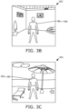
- FIG. 3B is an exemplary illustration of a given image 302 of the real-world environment that is captured by at least one camera (not shown) of a display apparatus (not shown)
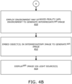
- FIG. 3C is an exemplary illustration of a mixed-reality image 304, in accordance with an embodiment of the present disclosure.
- the real-world environment is represented as an indoor environment of a room.
- the image 300 represents stationary objects present in the real-world environment. These stationary objects as depicted as a plant, wall paintings, paper rolls, and the like.
- the image 300 may be a part of a three-dimensional model of the real-world environment.
- the given image 302 represents an object 306, which is a person, in addition to the stationary objects represented in the image 300.
- the given image 302 is captured with respect to a pose of the user's head.
- the object 306 is detected by comparing a plurality of features extracted from a region of the three-dimensional model that corresponds to said pose of the user's head with a plurality of features extracted from the given image 302. Said region is, for example, represented in the image 300.
- the mixed-reality (MR) image 304 represents, for example, a mixed-reality (MR) beach environment.
- the mixed-reality beach environment includes virtual beach scenery as well as the object 306.
- the object 306 is embedded in an intermediate MR image (not shown) to generate the MR image 304.
- An environment map of the MR beach environment is employed to generate the intermediate MR image representing the virtual beach scenery (including, for example, virtual beach sand, virtual beach umbrella, virtual clouds, virtual beach beds, and the like).
- a display apparatus comprising at least one light source, at least one camera, and head-tracking means.
- a three-dimensional model of a real-world environment is obtained.
- the at least one camera is controlled to capture a given image of the real-world environment, whilst head-tracking data obtained from the head-tracking means is processed to determine a pose of a user's head with respect to which the given image is captured.
- a region of the three-dimensional model that corresponds to said pose of the user's head is determined.
- a plurality of features extracted from the region of the three-dimensional model are compared with a plurality of features extracted from the given image, to detect at least one object present in the real-world environment.
- an environment map of a mixed-reality environment is employed to generate an intermediate mixed-reality image based on the pose of the user's head.
- the at least one object in the intermediate mixed-reality image is embedded to generate a mixed-reality image.
- the mixed-reality image is displayed via the at least one light source.
Landscapes
- Engineering & Computer Science (AREA)
- Theoretical Computer Science (AREA)
- Physics & Mathematics (AREA)
- General Physics & Mathematics (AREA)
- General Engineering & Computer Science (AREA)
- Computer Graphics (AREA)
- Computer Vision & Pattern Recognition (AREA)
- Software Systems (AREA)
- Computer Hardware Design (AREA)
- Human Computer Interaction (AREA)
- Geometry (AREA)
- Processing Or Creating Images (AREA)
Claims (16)
- Appareil d'affichage (100, 200) comprenant :au moins une source de lumière (102, 202) ;au moins une caméra (104, 204) ;un moyen de suivi de tête (106, 206) ; etau moins un processeur (108, 208) configuré pour :- obtenir un modèle tridimensionnel d'un environnement de monde réel ;- commander l'au moins une caméra pour capturer une image donnée (302) de l'environnement de monde réel, tout en traitant des données de suivi de tête obtenues à partir du moyen de suivi de tête pour déterminer une posture de la tête d'un utilisateur par rapport à laquelle l'image donnée est capturée ;- déterminer une région du modèle tridimensionnel qui correspond à ladite posture de la tête de l'utilisateur ;- comparer une pluralité de caractéristiques extraites de la région du modèle tridimensionnel à une pluralité de caractéristiques extraites de l'image donnée, pour détecter au moins un objet (306) présent dans l'environnement de monde réel ;- recourir à une carte d'environnement d'un environnement de réalité mixte pour générer une image de réalité mixte intermédiaire en fonction de la posture de la tête de l'utilisateur ;- incorporer l'au moins un objet dans l'image de réalité mixte intermédiaire pour générer une image de réalité mixte (304) ; et- afficher l'image de réalité mixte par l'intermédiaire de l'au moins une source de lumière.
- Appareil d'affichage (100, 200) selon la revendication 1, dans lequel l'au moins un processeur (108, 208) est configuré pour :- générer une carte de profondeur de l'environnement de monde réel à partir de la posture de la tête de l'utilisateur par rapport à laquelle l'image donnée (302) est capturée ; et- déterminer à partir de la carte de profondeur une profondeur optique d'un pixel donné au sein d'un segment d'image de l'image donnée, le segment d'image représentant l'au moins un objet (306),dans lequel, lors de l'incorporation de l'au moins un objet, l'au moins un processeur est configuré pour :- détecter si la profondeur optique du pixel donné de l'image donnée se trouve à plus ou moins un seuil de profondeur prédéfini ; et- recouvrir le pixel donné de l'image donnée sur l'image de réalité mixte intermédiaire lorsque la profondeur optique du pixel donné se trouve à plus ou moins le seuil de profondeur prédéfini.
- Appareil d'affichage (100, 200) selon la revendication 2, dans lequel l'au moins un processeur (108, 208) est configuré pour :- obtenir des données tridimensionnelles représentatives d'une surface de délimitation au sein de l'environnement de monde réel ; et- déterminer le seuil de profondeur prédéfini à partir des données tridimensionnelles, en fonction d'un vecteur de direction pointant vers le pixel donné.
- Appareil d'affichage (100, 200) selon l'une quelconque des revendications précédentes, comprenant en outre un moyen de suivi d'objet (210), dans lequel l'au moins un processeur (108, 208) est configuré pour traiter des données de suivi d'objet, obtenues à partir du moyen de suivi d'objet, pour déterminer une position de l'au moins un objet (306) par rapport à la tête de l'utilisateur,
dans lequel, lors de la génération de l'image de réalité mixte (304), l'au moins un processeur est configuré pour incorporer l'au moins un objet dans l'image de réalité mixte intermédiaire en fonction de la position de l'au moins un objet par rapport à la tête de l'utilisateur. - Appareil d'affichage (100, 200) selon l'une quelconque des revendications précédentes, dans lequel l'au moins un processeur (108, 208) est configuré pour virtualiser au moins partiellement l'au moins un objet (306) avant incorporation de l'au moins un objet dans l'image de réalité mixte intermédiaire.
- Appareil d'affichage (100, 200) selon l'une quelconque des revendications précédentes, dans lequel, lors de l'obtention du modèle tridimensionnel de l'environnement de monde réel, l'au moins un processeur (108, 208) est configuré pour :- commander l'au moins une caméra (104, 204) pour capturer une pluralité d'images de l'environnement de monde réel, tout en traitant des données de suivi de tête obtenues à partir du moyen de suivi de tête (106, 206) pour déterminer des postures correspondantes de la tête de l'utilisateur par rapport auxquelles la pluralité d'images sont capturées ; et- traiter la pluralité d'images, en fonction des postures correspondantes de la tête de l'utilisateur, pour créer le modèle tridimensionnel de l'environnement de monde réel.
- Appareil d'affichage (100, 200) selon la revendication 6, dans lequel l'au moins un processeur (108, 208) est configuré pour :- générer une pluralité de cartes de profondeur de l'environnement de monde réel à partir des postures correspondantes de la tête de l'utilisateur par rapport auxquelles la pluralité d'images sont capturées ; et- recourir à la pluralité de cartes de profondeur lors de la création du modèle tridimensionnel de l'environnement de monde réel.
- Appareil d'affichage (100, 200) selon l'une quelconque des revendications précédentes, dans lequel l'au moins un processeur (108, 208) est configuré pour appliquer une transformation à l'image donnée (302) pour faire correspondre l'image donnée avec la région du modèle tridimensionnel avant comparaison.
- Procédé d'affichage, le procédé étant implémenté par un appareil d'affichage (100, 200) comprenant au moins une source de lumière (102, 202), au moins une caméra (104, 204), un moyen de suivi de tête (106, 206) et au moins un processeur (108, 208), le procédé comprenant :- l'obtention d'un modèle tridimensionnel d'un environnement de monde réel ;- la commande de l'au moins une caméra pour capturer une image donnée (302) de l'environnement de monde réel, tout en traitant des données de suivi de tête obtenues à partir du moyen de suivi de tête pour déterminer une posture de la tête d'un utilisateur par rapport à laquelle l'image donnée est capturée ;- la détermination d'une région du modèle tridimensionnel qui correspond à ladite posture de la tête de l'utilisateur ;- la comparaison d'une pluralité de caractéristiques extraites de la région du modèle tridimensionnel à une pluralité de caractéristiques extraites de l'image donnée, pour détecter au moins un objet (306) présent dans l'environnement de monde réel ;- le recours à une carte d'environnement d'un environnement de réalité mixte pour générer une image de réalité mixte intermédiaire en fonction de la posture de la tête de l'utilisateur ;- l'incorporation de l'au moins un objet dans l'image de réalité mixte intermédiaire pour générer une image de réalité mixte (304) ; et- l'affichage de l'image de réalité mixte par l'intermédiaire de l'au moins une source de lumière.
- Procédé selon la revendication 9, comprenant en outre :- la génération d'une carte de profondeur de l'environnement de monde réel à partir de la posture de la tête de l'utilisateur par rapport à laquelle l'image donnée (302) est capturée ; et- la détermination à partir de la carte de profondeur d'une profondeur optique d'un pixel donné au sein d'un segment d'image de l'image donnée, le segment d'image représentant l'au moins un objet (306),dans lequel l'étape d'incorporation de l'au moins un objet comprend :- le fait de détecter si la profondeur optique du pixel donné de l'image donnée se trouve à plus ou moins un seuil de profondeur prédéfini ; et- le recouvrement du pixel donné de l'image donnée sur l'image de réalité mixte intermédiaire lorsque la profondeur optique du pixel donné se trouve à plus ou moins le seuil de profondeur prédéfini.
- Procédé selon la revendication 10, comprenant en outre :- l'obtention de données tridimensionnelles représentatives d'une surface de délimitation au sein de l'environnement de monde réel ; et- la détermination du seuil de profondeur prédéfini à partir des données tridimensionnelles, en fonction d'un vecteur de direction pointant vers le pixel donné.
- Procédé selon l'une quelconque des revendications 9 à 11, dans lequel l'appareil d'affichage (100, 200) comprend en outre un moyen de suivi d'objet (210), le procédé comprenant en outre le traitement de données de suivi d'objet, obtenues à partir du moyen de suivi d'objet, pour déterminer une position de l'au moins un objet (306) par rapport à la tête de l'utilisateur,
dans lequel l'étape d'incorporation de l'au moins un objet dans l'image de réalité mixte intermédiaire est mise en oeuvre en fonction de la position de l'au moins un objet par rapport à la tête de l'utilisateur. - Procédé selon l'une quelconque des revendications 9 à 12, comprenant en outre la virtualisation au moins partielle de l'au moins un objet (306) avant incorporation de l'au moins un objet dans l'image de réalité mixte intermédiaire.
- Procédé selon l'une quelconque des revendications 9 à 13, dans lequel l'étape d'obtention du modèle tridimensionnel de l'environnement de monde réel comprend :- la commande de l'au moins une caméra (104, 204) pour capturer une pluralité d'images de l'environnement de monde réel, tout en traitant des données de suivi de tête obtenues à partir du moyen de suivi de tête (106, 206) pour déterminer des postures correspondantes de la tête de l'utilisateur par rapport auxquelles la pluralité d'images sont capturées ; et- le traitement de la pluralité d'images, en fonction des postures correspondantes de la tête de l'utilisateur, pour créer le modèle tridimensionnel de l'environnement de monde réel.
- Procédé selon la revendication 14, comprenant en outre :- la génération d'une pluralité de cartes de profondeur de l'environnement de monde réel à partir des postures correspondantes de la tête de l'utilisateur par rapport auxquelles la pluralité d'images sont capturées ; et- le recours à la pluralité de cartes de profondeur lors de la création du modèle tridimensionnel de l'environnement de monde réel.
- Procédé selon l'une quelconque des revendications 9 à 15, comprenant en outre l'application d'une transformation à l'image donnée (302) pour faire correspondre l'image donnée avec la région du modèle tridimensionnel avant comparaison.
Applications Claiming Priority (1)
| Application Number | Priority Date | Filing Date | Title |
|---|---|---|---|
| US17/171,392 US11315334B1 (en) | 2021-02-09 | 2021-02-09 | Display apparatuses and methods incorporating image masking |
Publications (3)
| Publication Number | Publication Date |
|---|---|
| EP4050400A1 EP4050400A1 (fr) | 2022-08-31 |
| EP4050400C0 EP4050400C0 (fr) | 2023-09-06 |
| EP4050400B1 true EP4050400B1 (fr) | 2023-09-06 |
Family
ID=80446656
Family Applications (1)
| Application Number | Title | Priority Date | Filing Date |
|---|---|---|---|
| EP22152269.1A Active EP4050400B1 (fr) | 2021-02-09 | 2022-01-19 | Appareils et procédés d'affichage intégrant un masquage d'images |
Country Status (2)
| Country | Link |
|---|---|
| US (1) | US11315334B1 (fr) |
| EP (1) | EP4050400B1 (fr) |
Families Citing this family (3)
| Publication number | Priority date | Publication date | Assignee | Title |
|---|---|---|---|---|
| CN115131440A (zh) * | 2022-06-15 | 2022-09-30 | 上海交通大学 | 一种基于双目相机的船体破损识别方法 |
| US20250238078A1 (en) * | 2024-01-22 | 2025-07-24 | Pixieray Oy | Method and system of gaze-mapping in real-world environment |
| US20250336219A1 (en) * | 2024-04-24 | 2025-10-30 | Varjo Technologies Oy | Three-dimensional object identification and segmentation |
Family Cites Families (6)
| Publication number | Priority date | Publication date | Assignee | Title |
|---|---|---|---|---|
| US8643569B2 (en) * | 2010-07-14 | 2014-02-04 | Zspace, Inc. | Tools for use within a three dimensional scene |
| US9595127B2 (en) * | 2010-12-22 | 2017-03-14 | Zspace, Inc. | Three-dimensional collaboration |
| US9286711B2 (en) * | 2011-09-30 | 2016-03-15 | Microsoft Technology Licensing, Llc | Representing a location at a previous time period using an augmented reality display |
| WO2014148394A1 (fr) * | 2013-03-19 | 2014-09-25 | 株式会社日立国際電気 | Dispositif d'affichage d'image et procédé d'affichage d'image |
| US10665034B2 (en) * | 2018-02-17 | 2020-05-26 | Varjo Technologies Oy | Imaging system, display apparatus and method of producing mixed-reality images |
| US11328486B2 (en) * | 2019-04-30 | 2022-05-10 | Google Llc | Volumetric capture of objects with a single RGBD camera |
-
2021
- 2021-02-09 US US17/171,392 patent/US11315334B1/en active Active
-
2022
- 2022-01-19 EP EP22152269.1A patent/EP4050400B1/fr active Active
Also Published As
| Publication number | Publication date |
|---|---|
| EP4050400C0 (fr) | 2023-09-06 |
| EP4050400A1 (fr) | 2022-08-31 |
| US11315334B1 (en) | 2022-04-26 |
Similar Documents
| Publication | Publication Date | Title |
|---|---|---|
| US10701332B2 (en) | Image processing apparatus, image processing method, image processing system, and storage medium | |
| US10659750B2 (en) | Method and system for presenting at least part of an image of a real object in a view of a real environment, and method and system for selecting a subset of a plurality of images | |
| JP7250709B2 (ja) | 畳み込み画像変換を使用して同時位置特定およびマッピングを実施する方法およびシステム | |
| JP7566973B2 (ja) | 情報処理装置、情報処理方法及びプログラム | |
| EP2992508B1 (fr) | Effets de réalité diminuée et médiatisée à partir de reconstruction | |
| JP7162750B2 (ja) | 画像処理装置、画像処理方法、及び、プログラム | |
| US20230245396A1 (en) | System and method for three-dimensional scene reconstruction and understanding in extended reality (xr) applications | |
| EP4050400B1 (fr) | Appareils et procédés d'affichage intégrant un masquage d'images | |
| US20150262412A1 (en) | Augmented reality lighting with dynamic geometry | |
| WO2016029939A1 (fr) | Procédé et système pour déterminer au moins une caractéristique d'image dans au moins une image | |
| CN103262126B (zh) | 图像处理装置、照明处理装置及其方法 | |
| WO2019140945A1 (fr) | Procédé de réalité mixte appliqué à un simulateur de vol | |
| EP4134917B1 (fr) | Systèmes et procédés d'imagerie pour faciliter l'éclairage local | |
| JP7403967B2 (ja) | 情報処理装置、映像生成装置、画像処理システム、それらの制御方法及びプログラム | |
| EP4036858A1 (fr) | Imagerie volumétrique | |
| JP2016071645A (ja) | オブジェクト3次元モデル復元方法、装置およびプログラム | |
| US20180286130A1 (en) | Graphical image augmentation of physical objects | |
| US11727658B2 (en) | Using camera feed to improve quality of reconstructed images | |
| JP2018116421A (ja) | 画像処理装置および画像処理方法 | |
| CN115398483A (zh) | 用目标三维(3d)对象增强监视空间的录像片段以训练人工智能(ai)模型的方法和系统 | |
| WO2022195157A1 (fr) | Détection d'objet d'essai pour superposition virtuelle | |
| EP4224429B1 (fr) | Systèmes et procédés pour indiquer visuellement un contenu périmé dans un modèle d'environnement | |
| EP4261783A1 (fr) | Utilisation d'informatique en nuage pour améliorer la précision de suivi de pose | |
| US11568552B2 (en) | Imaging systems and methods incorporating improved culling of virtual objects | |
| US20250336219A1 (en) | Three-dimensional object identification and segmentation |
Legal Events
| Date | Code | Title | Description |
|---|---|---|---|
| PUAI | Public reference made under article 153(3) epc to a published international application that has entered the european phase |
Free format text: ORIGINAL CODE: 0009012 |
|
| STAA | Information on the status of an ep patent application or granted ep patent |
Free format text: STATUS: THE APPLICATION HAS BEEN PUBLISHED |
|
| AK | Designated contracting states |
Kind code of ref document: A1 Designated state(s): AL AT BE BG CH CY CZ DE DK EE ES FI FR GB GR HR HU IE IS IT LI LT LU LV MC MK MT NL NO PL PT RO RS SE SI SK SM TR |
|
| STAA | Information on the status of an ep patent application or granted ep patent |
Free format text: STATUS: REQUEST FOR EXAMINATION WAS MADE |
|
| 17P | Request for examination filed |
Effective date: 20230208 |
|
| RBV | Designated contracting states (corrected) |
Designated state(s): AL AT BE BG CH CY CZ DE DK EE ES FI FR GB GR HR HU IE IS IT LI LT LU LV MC MK MT NL NO PL PT RO RS SE SI SK SM TR |
|
| GRAP | Despatch of communication of intention to grant a patent |
Free format text: ORIGINAL CODE: EPIDOSNIGR1 |
|
| STAA | Information on the status of an ep patent application or granted ep patent |
Free format text: STATUS: GRANT OF PATENT IS INTENDED |
|
| RIC1 | Information provided on ipc code assigned before grant |
Ipc: G06T 15/50 20060101ALI20230224BHEP Ipc: G06T 7/73 20170101ALI20230224BHEP Ipc: G06T 19/00 20110101ALI20230224BHEP Ipc: G06F 3/01 20060101ALI20230224BHEP Ipc: G02B 27/01 20060101ALI20230224BHEP Ipc: G02B 27/00 20060101AFI20230224BHEP |
|
| INTG | Intention to grant announced |
Effective date: 20230323 |
|
| GRAS | Grant fee paid |
Free format text: ORIGINAL CODE: EPIDOSNIGR3 |
|
| GRAA | (expected) grant |
Free format text: ORIGINAL CODE: 0009210 |
|
| STAA | Information on the status of an ep patent application or granted ep patent |
Free format text: STATUS: THE PATENT HAS BEEN GRANTED |
|
| AK | Designated contracting states |
Kind code of ref document: B1 Designated state(s): AL AT BE BG CH CY CZ DE DK EE ES FI FR GB GR HR HU IE IS IT LI LT LU LV MC MK MT NL NO PL PT RO RS SE SI SK SM TR |
|
| REG | Reference to a national code |
Ref country code: GB Ref legal event code: FG4D |
|
| REG | Reference to a national code |
Ref country code: CH Ref legal event code: EP |
|
| REG | Reference to a national code |
Ref country code: DE Ref legal event code: R096 Ref document number: 602022000423 Country of ref document: DE |
|
| REG | Reference to a national code |
Ref country code: IE Ref legal event code: FG4D |
|
| U01 | Request for unitary effect filed |
Effective date: 20230926 |
|
| U07 | Unitary effect registered |
Designated state(s): AT BE BG DE DK EE FI FR IT LT LU LV MT NL PT SE SI Effective date: 20231002 |
|
| PG25 | Lapsed in a contracting state [announced via postgrant information from national office to epo] |
Ref country code: GR Free format text: LAPSE BECAUSE OF FAILURE TO SUBMIT A TRANSLATION OF THE DESCRIPTION OR TO PAY THE FEE WITHIN THE PRESCRIBED TIME-LIMIT Effective date: 20231207 |
|
| PG25 | Lapsed in a contracting state [announced via postgrant information from national office to epo] |
Ref country code: RS Free format text: LAPSE BECAUSE OF FAILURE TO SUBMIT A TRANSLATION OF THE DESCRIPTION OR TO PAY THE FEE WITHIN THE PRESCRIBED TIME-LIMIT Effective date: 20230906 Ref country code: NO Free format text: LAPSE BECAUSE OF FAILURE TO SUBMIT A TRANSLATION OF THE DESCRIPTION OR TO PAY THE FEE WITHIN THE PRESCRIBED TIME-LIMIT Effective date: 20231206 Ref country code: HR Free format text: LAPSE BECAUSE OF FAILURE TO SUBMIT A TRANSLATION OF THE DESCRIPTION OR TO PAY THE FEE WITHIN THE PRESCRIBED TIME-LIMIT Effective date: 20230906 Ref country code: GR Free format text: LAPSE BECAUSE OF FAILURE TO SUBMIT A TRANSLATION OF THE DESCRIPTION OR TO PAY THE FEE WITHIN THE PRESCRIBED TIME-LIMIT Effective date: 20231207 |
|
| U20 | Renewal fee for the european patent with unitary effect paid |
Year of fee payment: 3 Effective date: 20240124 |
|
| PG25 | Lapsed in a contracting state [announced via postgrant information from national office to epo] |
Ref country code: IS Free format text: LAPSE BECAUSE OF FAILURE TO SUBMIT A TRANSLATION OF THE DESCRIPTION OR TO PAY THE FEE WITHIN THE PRESCRIBED TIME-LIMIT Effective date: 20240106 |
|
| PG25 | Lapsed in a contracting state [announced via postgrant information from national office to epo] |
Ref country code: ES Free format text: LAPSE BECAUSE OF FAILURE TO SUBMIT A TRANSLATION OF THE DESCRIPTION OR TO PAY THE FEE WITHIN THE PRESCRIBED TIME-LIMIT Effective date: 20230906 |
|
| PG25 | Lapsed in a contracting state [announced via postgrant information from national office to epo] |
Ref country code: SM Free format text: LAPSE BECAUSE OF FAILURE TO SUBMIT A TRANSLATION OF THE DESCRIPTION OR TO PAY THE FEE WITHIN THE PRESCRIBED TIME-LIMIT Effective date: 20230906 Ref country code: RO Free format text: LAPSE BECAUSE OF FAILURE TO SUBMIT A TRANSLATION OF THE DESCRIPTION OR TO PAY THE FEE WITHIN THE PRESCRIBED TIME-LIMIT Effective date: 20230906 Ref country code: IS Free format text: LAPSE BECAUSE OF FAILURE TO SUBMIT A TRANSLATION OF THE DESCRIPTION OR TO PAY THE FEE WITHIN THE PRESCRIBED TIME-LIMIT Effective date: 20240106 Ref country code: ES Free format text: LAPSE BECAUSE OF FAILURE TO SUBMIT A TRANSLATION OF THE DESCRIPTION OR TO PAY THE FEE WITHIN THE PRESCRIBED TIME-LIMIT Effective date: 20230906 Ref country code: CZ Free format text: LAPSE BECAUSE OF FAILURE TO SUBMIT A TRANSLATION OF THE DESCRIPTION OR TO PAY THE FEE WITHIN THE PRESCRIBED TIME-LIMIT Effective date: 20230906 Ref country code: SK Free format text: LAPSE BECAUSE OF FAILURE TO SUBMIT A TRANSLATION OF THE DESCRIPTION OR TO PAY THE FEE WITHIN THE PRESCRIBED TIME-LIMIT Effective date: 20230906 |
|
| PG25 | Lapsed in a contracting state [announced via postgrant information from national office to epo] |
Ref country code: PL Free format text: LAPSE BECAUSE OF FAILURE TO SUBMIT A TRANSLATION OF THE DESCRIPTION OR TO PAY THE FEE WITHIN THE PRESCRIBED TIME-LIMIT Effective date: 20230906 |
|
| REG | Reference to a national code |
Ref country code: DE Ref legal event code: R097 Ref document number: 602022000423 Country of ref document: DE |
|
| PLBE | No opposition filed within time limit |
Free format text: ORIGINAL CODE: 0009261 |
|
| STAA | Information on the status of an ep patent application or granted ep patent |
Free format text: STATUS: NO OPPOSITION FILED WITHIN TIME LIMIT |
|
| 26N | No opposition filed |
Effective date: 20240607 |
|
| PG25 | Lapsed in a contracting state [announced via postgrant information from national office to epo] |
Ref country code: MC Free format text: LAPSE BECAUSE OF FAILURE TO SUBMIT A TRANSLATION OF THE DESCRIPTION OR TO PAY THE FEE WITHIN THE PRESCRIBED TIME-LIMIT Effective date: 20230906 |
|
| PG25 | Lapsed in a contracting state [announced via postgrant information from national office to epo] |
Ref country code: MC Free format text: LAPSE BECAUSE OF FAILURE TO SUBMIT A TRANSLATION OF THE DESCRIPTION OR TO PAY THE FEE WITHIN THE PRESCRIBED TIME-LIMIT Effective date: 20230906 |
|
| PG25 | Lapsed in a contracting state [announced via postgrant information from national office to epo] |
Ref country code: IE Free format text: LAPSE BECAUSE OF NON-PAYMENT OF DUE FEES Effective date: 20240119 |
|
| PG25 | Lapsed in a contracting state [announced via postgrant information from national office to epo] |
Ref country code: IE Free format text: LAPSE BECAUSE OF NON-PAYMENT OF DUE FEES Effective date: 20240119 |
|
| U20 | Renewal fee for the european patent with unitary effect paid |
Year of fee payment: 4 Effective date: 20250128 |
|
| PG25 | Lapsed in a contracting state [announced via postgrant information from national office to epo] |
Ref country code: CY Free format text: LAPSE BECAUSE OF FAILURE TO SUBMIT A TRANSLATION OF THE DESCRIPTION OR TO PAY THE FEE WITHIN THE PRESCRIBED TIME-LIMIT; INVALID AB INITIO Effective date: 20220119 |
|
| REG | Reference to a national code |
Ref country code: CH Ref legal event code: PL |
|
| PG25 | Lapsed in a contracting state [announced via postgrant information from national office to epo] |
Ref country code: CH Free format text: LAPSE BECAUSE OF NON-PAYMENT OF DUE FEES Effective date: 20250131 |
|
| PG25 | Lapsed in a contracting state [announced via postgrant information from national office to epo] |
Ref country code: TR Free format text: LAPSE BECAUSE OF FAILURE TO SUBMIT A TRANSLATION OF THE DESCRIPTION OR TO PAY THE FEE WITHIN THE PRESCRIBED TIME-LIMIT Effective date: 20230906 |
|
| U20 | Renewal fee for the european patent with unitary effect paid |
Year of fee payment: 5 Effective date: 20260129 |
|
| PGFP | Annual fee paid to national office [announced via postgrant information from national office to epo] |
Ref country code: GB Payment date: 20260123 Year of fee payment: 5 |