EP4050742B1 - Installationskanalsystem zum brandschutz einer elektrokabelinstallation - Google Patents
Installationskanalsystem zum brandschutz einer elektrokabelinstallation Download PDFInfo
- Publication number
- EP4050742B1 EP4050742B1 EP21159130.0A EP21159130A EP4050742B1 EP 4050742 B1 EP4050742 B1 EP 4050742B1 EP 21159130 A EP21159130 A EP 21159130A EP 4050742 B1 EP4050742 B1 EP 4050742B1
- Authority
- EP
- European Patent Office
- Prior art keywords
- shell member
- split shell
- installation
- channel system
- shell element
- Prior art date
- Legal status (The legal status is an assumption and is not a legal conclusion. Google has not performed a legal analysis and makes no representation as to the accuracy of the status listed.)
- Active
Links
Images


Classifications
-
- H—ELECTRICITY
- H02—GENERATION; CONVERSION OR DISTRIBUTION OF ELECTRIC POWER
- H02G—INSTALLATION OF ELECTRIC CABLES OR LINES, OR OF COMBINED OPTICAL AND ELECTRIC CABLES OR LINES
- H02G3/00—Installations of electric cables or lines or protective tubing therefor in or on buildings, equivalent structures or vehicles
- H02G3/02—Details
- H02G3/04—Protective tubing or conduits, e.g. cable ladders or cable troughs
- H02G3/0406—Details thereof
- H02G3/0412—Heat or fire protective means
-
- A—HUMAN NECESSITIES
- A62—LIFE-SAVING; FIRE-FIGHTING
- A62C—FIRE-FIGHTING
- A62C2/00—Fire prevention or containment
- A62C2/06—Physical fire-barriers
- A62C2/065—Physical fire-barriers having as the main closure device materials, whose characteristics undergo an irreversible change under high temperatures, e.g. intumescent
-
- H—ELECTRICITY
- H02—GENERATION; CONVERSION OR DISTRIBUTION OF ELECTRIC POWER
- H02G—INSTALLATION OF ELECTRIC CABLES OR LINES, OR OF COMBINED OPTICAL AND ELECTRIC CABLES OR LINES
- H02G3/00—Installations of electric cables or lines or protective tubing therefor in or on buildings, equivalent structures or vehicles
- H02G3/02—Details
- H02G3/06—Joints for connecting lengths of protective tubing or channels, to each other or to casings, e.g. to distribution boxes; Ensuring electrical continuity in the joint
- H02G3/0608—Joints for connecting non cylindrical conduits, e.g. channels
-
- H—ELECTRICITY
- H02—GENERATION; CONVERSION OR DISTRIBUTION OF ELECTRIC POWER
- H02G—INSTALLATION OF ELECTRIC CABLES OR LINES, OR OF COMBINED OPTICAL AND ELECTRIC CABLES OR LINES
- H02G3/00—Installations of electric cables or lines or protective tubing therefor in or on buildings, equivalent structures or vehicles
- H02G3/26—Installations of cables, lines, or separate protective tubing therefor directly on or in walls, ceilings, or floors
- H02G3/263—Installation, e.g. suspension, of conduit channels or other supports
-
- A—HUMAN NECESSITIES
- A62—LIFE-SAVING; FIRE-FIGHTING
- A62C—FIRE-FIGHTING
- A62C3/00—Fire prevention, containment or extinguishing specially adapted for particular objects or places
- A62C3/16—Fire prevention, containment or extinguishing specially adapted for particular objects or places in electrical installations, e.g. cableways
-
- H—ELECTRICITY
- H02—GENERATION; CONVERSION OR DISTRIBUTION OF ELECTRIC POWER
- H02G—INSTALLATION OF ELECTRIC CABLES OR LINES, OR OF COMBINED OPTICAL AND ELECTRIC CABLES OR LINES
- H02G3/00—Installations of electric cables or lines or protective tubing therefor in or on buildings, equivalent structures or vehicles
- H02G3/02—Details
- H02G3/04—Protective tubing or conduits, e.g. cable ladders or cable troughs
- H02G3/0406—Details thereof
- H02G3/0418—Covers or lids; Their fastenings
-
- H—ELECTRICITY
- H02—GENERATION; CONVERSION OR DISTRIBUTION OF ELECTRIC POWER
- H02G—INSTALLATION OF ELECTRIC CABLES OR LINES, OR OF COMBINED OPTICAL AND ELECTRIC CABLES OR LINES
- H02G3/00—Installations of electric cables or lines or protective tubing therefor in or on buildings, equivalent structures or vehicles
- H02G3/02—Details
- H02G3/04—Protective tubing or conduits, e.g. cable ladders or cable troughs
- H02G3/0437—Channels
Definitions
- the invention relates to an installation duct system for fire protection of an electrical cable installation and a connector for adjacent ends of two cable duct sections of the installation duct system.
- electrical cable installations are typically laid in a duct system consisting of two or more interconnected cable duct sections, which can be adapted, for example, to the spatial conditions of a building.
- the two cable duct sections are each coated on the inside with an expandable intumescent material that expands at a specific temperature, sealing existing connection points and joints, as well as any existing cracks and gaps created by a fire.
- the expandable intumescent material prevents the spread of fire and smoke from the encased electrical cable installation.
- the DE 10 2007 050639 B4 discloses a self-supporting fire protection cladding made of prefabricated molded parts, with a dimensionally stable support made of a foil sheet with a thickness of up to 2 mm, the interior of which is fully coated with a foamable insulating layer with a thickness of 0.6 to 2.5 mm.
- a plug-in or sliding connection is proposed as the connection.
- the DE 100 43 355 A1 A fire-protected cable duct and a method for manufacturing the same are known.
- the cable duct is formed from a composite material consisting of a non-metallic fire protection material reinforced with a metal insert.
- a tray and a cover section are proposed as the connecting device, which are connected to each other via cap locks.
- a separate support serves to fasten the cable tray. This support can be attached to a ceiling via threaded rods or placed on a separate supporting structure.
- the disadvantage of the known installation duct systems is that connecting the cable duct sections is complex both in terms of production and during the installation process.
- the object of the present invention is therefore to provide an installation duct system for fire protection of an electrical cable installation and a connector for adjacent ends of the two cable duct sections, which are simpler in manufacture and during the installation process.
- the invention provides a connector according to claim 1 for an installation duct system and an installation duct system according to claim 2 comprising a connector according to claim 1.
- Advantageous embodiments are mentioned in the dependent claims 2 to 13.
- the connection is particularly simple and can therefore be manufactured more easily.
- the holding elements can be manufactured particularly cost-effectively using one or more standard components, such as screws, nuts, and the like.
- the through-holes of the first sub-shell element are designed as U-shaped recesses that are open in a transverse direction of the first sub-shell element, so that the first sub-shell element can be pushed along the transverse direction towards the connecting position when the flanges are placed on top of one another, the first sub-shell element can be brought together with the second sub-shell element while the holding elements are already inserted into the through-holes of the second sub-shell element. This simplifies the installation process of the connector.
- the installation duct system can be designed or used for laying electrical cable installations inside and/or outside buildings.
- the electrical cable installation can comprise one or more electrical cables.
- the electrical cables can be intended, for example, for power supply, data transmission, and/or control signals.
- the two cable duct sections can be straight, angled and/or curved cable duct sections.
- the two cable duct sections can enclose a duct- or tube-like cavity in which the electrical cable installation can be laid.
- the two cable duct sections can each comprise two halves that can be connected to each other, for example via a screw, clamp or snap mechanism.
- one of the Halves have a U-shaped base part that is closed with the other half as a lid.
- the foamable intumescent layer can be designed to expand at a specific temperature, thereby sealing existing connection points or joints and/or any existing cracks and gaps or those caused by the fire.
- the foamable intumescent layer also provides thermal insulation for the electrical cable installation it covers.
- the two cable duct sections and/or the connector can comprise metal parts. Since this material can be formed into almost any shape and is non-flammable, it is particularly suitable as an installation duct system for fire protection of electrical cable installations.
- Metal parts here can refer in particular to sheet metal parts, preferably with a thickness of less than 3 mm, especially less than 2 mm.
- the first partial shell element and/or the second partial shell element can be designed as bent sheet metal parts. This makes them particularly flexible and cost-effective to manufacture. Bent sheet metal parts can be metal parts with a maximum thickness of 3 mm, in particular 2 mm.
- the first partial shell element and/or the second partial shell element can, independently of one another, have a hat profile, a U-profile, an angle profile, and/or a flat profile in cross-section. It is conceivable that the ends of the aforementioned profiles form the flanges. For example, at least one end of the aforementioned profiles can be beveled and form at least one of the flanges. Likewise, at least one end of the aforementioned profiles can merge straight into at least one of the flanges.
- the through-holes can be formed in the flanges. "Through-holes" can mean openings that extend completely through the thickness of the flanges.
- the through-holes in the second partial shell element can be designed as through-bores or threads and/or have a circular cross-section.
- the through-holes of the first partial shell element which are designed as U-shaped recesses, can deviate from a circular shape in cross-section and/or be partially open in cross-section.
- the transverse direction of the first partial shell element can run parallel to the laterally projecting flanges of the first partial shell element.
- the first partial shell element be designed as a bent sheet metal part, wherein at least one of the laterally projecting flanges is bent along a bending line, and wherein the transverse direction runs parallel to the bending line.
- the flanges of the first partial shell element and the second partial shell element can lie on top of each other in pairs, so that they are in surface contact with each other.
- the through-holes of the first partial shell element can be aligned correspondingly and/or coaxially with the through-holes of the second partial shell element.
- the connector is designed for attachment to at least one attachment point in order to form a holder for the two cable duct sections after the first partial shell element has been connected to the second partial shell element, in particular on a wall, a ceiling, a supporting structure (cable tray, cable ladder), console and/or a floor of a building.
- the holding elements running through the through-holes of the second partial shell element are designed for attachment to the at least one attachment point. This means that the holding elements can be used both to connect the first partial shell element to the second partial shell element and to hold it at the attachment point. In particular, for attachment the holding elements run through the through-holes of both the first partial shell element and the second partial shell element.
- the second partial shell element can be attached to the at least one fastening point via the holding elements, independently of the connection to the first partial shell element, in order to form a bearing for the adjacent ends of the two cable duct sections during an installation process.
- the second partial shell element can thus initially be used as a supporting shell for the two cable duct sections during the installation process, so that the electrical cable installation can be inserted into the two cable duct sections particularly easily. It is conceivable that the two cable duct sections are open during this process.
- the first partial shell element can then be inserted into the connecting position and then connected to the second partial shell element without loosening the holding elements from the second partial shell element due to the design of the through-holes as U-shaped recesses. This makes the installation process particularly simple.
- the term "installation process” here can mean the laying of the two cable duct sections and/or the insertion of the electrical cable installation into the two cable duct sections.
- the retaining elements can be designed for direct attachment to the at least one attachment point. This makes the installation duct system particularly cost-effective.
- the retaining elements can be designed at least partially as threaded rods that, in the connected position, extend through the through-holes of the first partial shell element and the second partial shell element, wherein the retaining elements can be attached to the at least one attachment point.
- the retaining elements can be designed with a screw thread at their ends, each of which can be screwed into a respective attachment point, for example, using a dowel.
- the installation duct system can comprise a support for attachment to the at least one attachment point, wherein the holding elements can be connected directly to the support.
- the support here can, for example, be an angled support with two legs, one leg being connectable to the attachment point and the other leg to the holding elements. It can also be a rod-like support that can be connected to the attachment point at one section and to the holding elements at another section.
- the first partial shell element and/or the second partial shell element are coated with a foamable insulator. This improves fire protection in the area of the connector.
- the foamable insulator of the first partial shell element and/or the second partial shell element can be designed in the same way as the foamable insulator previously described with reference to the two cable duct sections.
- the retaining elements can each comprise a rod, a bolt, a threaded rod, a nut, and/or a screw. This allows the retaining elements to be designed particularly simply, in particular as standard parts, and is therefore particularly cost-effective.
- the retaining elements can be designed as a rod, in particular as a threaded rod, which is designed at one end to connect the first partial shell element and the second partial shell element and at the other end to connect to the fastening point. Screws and/or nuts can also be used as retaining elements to clamp the first partial shell element and the second partial shell element.
- At least one of the holding elements can be designed as a clamping element to connect the first partial shell element and the second partial shell element via a clamping effect.
- at least one of the holding elements is designed with a thread and nuts in order to achieve the clamping effect.
- the first sub-shell element, the second sub-shell element, and/or the adjacent ends of the two cable duct sections can comprise at least one sealing strip to seal an interior of the two cable duct sections from the environment. This prevents the supply of additional oxygen from the environment in the event of a fire. It can also prevent the penetration of moisture into the two cable duct sections.
- the sealing strip can comprise a flexible layer of rubber or foam to support the sealing effect.
- the two cable duct sections can each comprise a formed sheet metal part. This allows them to be manufactured particularly cost-effectively.
- the two cable duct sections can each comprise a U-shaped base section and a cover that can be connected to it.
- the cover can be connected to the U-shaped base section via a screw, clamp, or snap connection.
- the two cable duct sections can each include a clip-on strip at the adjacent ends. This can protect the electrical cable installation from damage and/or a person from injury.
- the adjacent ends of the two cable duct sections can comprise support elements to support a clamping effect of the first partial shell element and/or the second partial shell element. This can prevent bending when the two cable duct sections are designed to be wide.
- the support elements can, for example, be designed as bent sheet metal parts that are angled at their ends and connected to the two cable duct sections there. This allows the support elements to be designed particularly simply. However, it is also conceivable for the support elements to be made of plastic.
- the support elements can each be firmly connected at least on one side to one of the two cable duct sections, in particular by means of an adhesive or welding point.
- the support elements can, in particular, be designed as support plates, with the ends being angled.
- the support elements can preferably be used when the two cable duct sections are at least 260 mm wide.
- the invention provides a connector for adjacent ends of two cable duct sections of the installation duct system to solve the above-mentioned problem.
- the connection is particularly simple and can therefore be manufactured more easily.
- the holding elements can be manufactured particularly cost-effectively using one or more standard components, such as screws, nuts, and the like.
- the through-holes of the first sub-shell element are designed as U-shaped recesses that are open in a transverse direction of the first sub-shell element, so that the first sub-shell element can be pushed along the transverse direction towards the connecting position when the flanges are placed on top of one another, the first sub-shell element can be brought together with the second sub-shell element while the holding elements are already inserted into the through-holes of the second sub-shell element. This simplifies the installation process of the connector.
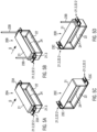
- FIG. 1A - 1B An example of an installation duct system for fire protection of an electrical cable installation I is shown in a perspective view.
- Figure 1A Two cable duct sections 10A and 10B, each comprising a U-shaped base section 10.2 and a cover 10.1 that can be used with it, and which are designed as formed sheet metal parts. On the inside, they are coated with the expandable insulating layer 10.3, which expands at a certain temperature and thereby seals existing connection points or joints and cracks and gaps caused by a fire. This thermally insulates the electrical cable installation I and stops the oxygen supply to the fire. This can prevent the fire from spreading beyond the installation duct system.
- the cover 10.1 engages the U-shaped base section 10.2 via a snap mechanism (not shown here).
- the connector 20A for the adjacent ends of the two cable duct sections 10A and 10B can be seen.
- the connector 20A comprises the first partial shell element 21 and the second partial shell element 22 with the laterally projecting flanges 21.2 and 22.2, respectively, which, when placed one on top of the other, can be connected to one another in the connecting position by means of the holding elements 23A extending through the through holes 21.3, 22.3.
- a third cable duct section 10C can be seen, which is designed in the same way as the two cable duct sections 10A, 10B.
- the cable duct section 10C is connected to the cable duct section 10B via a further connector 20B.
- the first partial shell element 21 and the second partial shell element of the connectors 20A, 20B are described below with reference to the Figure 2 explained in more detail.
- the connector 20B differs from the connector 20A only in the design of the retaining elements 23B extending through the through holes 21.3, 22.3:
- the retaining elements 23A are designed as screws with nuts, which connect the first partial shell element and the second partial shell element 21 or 22 via a clamping action. This will be explained further below with reference to the Figures 3A - 3B explained in more detail.
- the holding elements 23B are designed as threaded rods and serve to fasten the cable duct sections 10B, 10C to fastening points. This will be explained further below using the Figures 4A - 4C explained in more detail.
- FIG 2 is an embodiment of the connector 20A for adjacent ends of the two cable duct sections 10A, 10B of the installation duct system 1 from the Figures 1A - 1B in a top view.
- the embodiment applies equally to the other connector 20B of the Figures 1A - 1B .
- the first partial shell element 21 and the second partial shell element 22 can be seen, which are designed as bent sheet metal parts and have a hat profile (see Fig. 3A , 5A and 5B ). Accordingly, the first partial shell element 21 consists of the folded sheet metal 21.1, which is bent twice in opposite directions at each end, thereby forming the two flanges 21.2. Accordingly, the second partial shell element 22, as a folded sheet metal 22.1, is bent twice in opposite directions at each end, forming the flanges 22.2.
- the second partial shell element 22 has two through holes 22.3, which are designed here as through holes with a circular cross section.
- the through holes 21.3 of the first partial shell element 21 are formed as U-shaped recesses which are open in the transverse direction Q of the first partial shell element.
- the retaining elements 23A designed as screws can already be inserted in the connector 20A and then the first partial shell element 21 can be pushed along the transverse direction Q to a connecting position with the flanges 21.2, 22.2 placed on top of one another.
- the second partial shell element 22 can be provided with the holding elements 23B designed as threaded rods and fastened to a wall, a ceiling, and/or a floor of a building, so that the two cable duct sections 10B, 10C can be inserted therein during an installation process. Subsequently, the first partial shell element 21 can be pushed along the transverse direction Q toward a connecting position with the flanges 21.2, 22.2 placed on top of one another, without the holding elements 23B having to be removed from the second partial shell element 22.
- the connector 20A is from the Figures 1A - 1B shown in more detail in a sectional view and in a detailed view AA. It can be seen that the first partial shell element 21 and the second partial shell element 22 form the adjacent ends of the two cable duct sections 10A, 10B together to form a sealed connection. As already mentioned with regard to the Figure 2 As described, the two partial shell elements 21, 22 are designed as a hat profile and in the connected state the flanges 21.2, 22.2 rest on one another and are connected to one another via the holding elements 23A designed as screws.
- first partial shell element 21 and the second partial shell element 22 are provided with sealing strips 24, so that the outer sides of the two cable duct sections 10A, 10B are sealed from the inside of the connector 20A. This seals off the interior of the two cable duct sections 10A, 10B from the environment, so that in the event of a fire, no oxygen is supplied, and no moisture can penetrate during normal operation.
- the two cable duct sections 10A, 10B each enclose the plug-in strip 25 at the adjacent ends. This prevents injuries to the electrical cable installation I or to persons during the installation process.
- the other connector 20B is from the Figures 1A - 1B shown in a sectional view and in two detailed views.
- the connector 20B differs from the connector 20A only in the design of the holding elements 23B, which are designed as threaded rods.
- the connector 20B can thereby be used for fastening to the fastening point P, so that it forms a holder for the two cable duct sections 10B, 10C after the connection of the first partial shell element 21 to the second partial shell element 22.
- the installation duct system I comprises the support 26 for attachment to the attachment point P, for example, on a wall of a building. It can also be seen that the support 26 is angled with two legs. One leg has through holes into which the holding elements 23B can be inserted and screwed using nuts.
- the holding elements 23B are designed as threaded rods, which can be adjusted on site to the installation height of the two cable duct sections 10B, 10C as required.
- the other leg of the support 26 is provided with a further through-hole so that it can be fastened to the fastening point P by means of the screw 27, for example by means of a dowel.
- the connector 20B corresponds to the connector 20A from the Figures 3A - 3B .
- the two cable duct sections 10B, 10C are also provided with the plug-in strips 25 at the adjacent ends.
- connectors 20A, 20B are from the Figures 3A - 3B 4A - 4C are shown in a perspective view.
- connectors 20A and 20B are shown without the two cable duct sections.
- the two partial shell elements 21, 22 are designed as hat profiles. It can also be seen that the through holes 21.3 of the first partial shell element 21 are designed as U-shaped recesses that are open in the transverse direction Q of the first partial shell element 21. This allows the first partial shell element 21 to be pushed along the transverse direction Q to the illustrated connection position when the flanges 21.2, 22.2 are placed on top of one another.
- the sealing strips 24 on the inside of the two partial shell elements 21, 22 are also clearly visible.
- FIGS 5C - 5D are further embodiments of connectors 20C, 20D for adjacent ends of the two cable duct sections 10A - 10C of the installation duct system 1 from the Figures 1A - 1B shown in perspective views.
- first partial shell element 21 is designed as an angle profile with beveled flanges 21.2.
- second partial shell element 22 is designed as an angle profile that does not require any bevels and transitions straight into the flanges 22.2.
- the two retaining elements 23C are designed as screws, with which the connector 20C can be attached to fastening points in a corner of the room. It is also conceivable that the retaining elements 23C may be self-attached, or that other types of retaining elements may be used.
- the connector 20D is designed for direct attachment to the wall with the holding element 23C and for attachment to a ceiling via the holding element 23B: It can be seen that the first partial shell element 21 is designed as an angle profile with beveled flanges 21.2.
- the second partial shell element 22 is designed as a U-profile and has a straight flange 22.2 on one side, which does not require any beveling, whereas the other flange 22.2 is beveled.
- the second partial shell element 22 it is possible to attach the second partial shell element 22 to at least one fastening point P via the holding elements 23B, 23C, independently of the connection to the first partial shell element 21.
- This allows the two cable duct sections 10A, 10B to be initially inserted and stored in the second partial shell element 22.
- the electrical cable installation I can then be inserted into the two or three cable duct sections 10A-10C, for example, with the lid open.
- the lid can then be closed and the first partial shell element 21 pushed along the transverse direction Q towards the connection position and then clamped with the holding elements 23A-23C without the holding elements 23A-23C being released from the second partial shell element 22.
- the two cable duct sections 10A-10C comprise the support elements 10.4 to support a clamping effect of the first partial shell element 21 and the second partial shell element 22. This prevents the duct walls from bulging, particularly in the case of wide cable duct sections 10A-10C, especially if they have a width of at least 260mm.
Landscapes
- Engineering & Computer Science (AREA)
- Architecture (AREA)
- Civil Engineering (AREA)
- Structural Engineering (AREA)
- Health & Medical Sciences (AREA)
- Public Health (AREA)
- Business, Economics & Management (AREA)
- Emergency Management (AREA)
- Installation Of Indoor Wiring (AREA)
Description
- Die Erfindung betrifft ein Installationskanalsystem zum Brandschutz einer Elektrokabelinstallation und einen Verbinder für einander benachbarte Enden von zwei Kabelkanalabschnitten des Installationskanalsystems.
- Üblicherweise wird eine Elektrokabelinstallation zum Zwecke des Brandschutzes in einem Installationskanalsystem verlegt, das zwei oder noch mehr miteinander verbundene Kabelkanalabschnitte umfasst, die beispielsweise an die räumlichen Gegebenheiten eines Gebäudes angepasst werden können. Die zwei Kabelkanalabschnitte sind jeweils innenseitig mit einem aufschäumbaren Dämmschichtbildner beschichtet, der bei einer bestimmten Temperatur aufschäumt und dadurch vorhandene Anschlussstellen bzw. -fugen sowie eventuell vorhandene oder durch den Brand entstehende Ritzen und Spalten abdichtet. Zudem verhindert der aufschäumbare Dämmschichtbildner eine Weiterleitung von Feuer und Rauch der damit umhüllten Elektrokabelinstallation.
- Die
DE 10 2007 050639 B4 offenbart eine selbsttragende Brandschutzverkleidung aus vorgefertigten Formteilen, wobei ein formstabiler Träger aus einem Folienblech mit einer Stärke bis zwei mm vorgesehen ist, und dessen Innenseite vollflächig mit einem aufschäumbaren Dämmschichtbildner mit einer Stärke von 0,6 bis 2,5 mm beschichtet ist. Als Verbindung wird eine Steck- oder Schiebeverbindung vorgeschlagen. - Des Weiteren ist aus der
DE 100 43 355 A1 ein brandgeschützter Kabelkanal und ein Verfahren zur Herstellung desselben bekannt. Der Kabelkanal ist aus einem Verbundwerkstoff gebildet, der aus einem nichtmetallischen Brandschutzmaterial besteht, das mit einer Metalleinlage verstärkt ist. Als Verbindungseinrichtung wird ein Rinnen- und ein Deckelteil vorgeschlagen, die über Kappenschlösser miteinander verbunden sind. Als Befestigung der Kabelrinne dient separat davon ein Träger, der über Gewindestangen an einer Decke befestigt werden kann oder auf einer separaten Tragkonstruktion aufgelegt werden kann. - Weitere Beispiele für bekannte brandgeschützte Kabelkanäle sind im Katalog "Fire Protection Systems", XP055538346, beschrieben.
- Beispiele für die Halterung von Rohrkanälen sind in der
US 539 462 A und in derEP 0 123 363 A1 beschrieben. - Nachteilig bei den bekannten Installationskanalsystemen ist, dass die Verbindung der Kabelkanalabschnitte sowohl in der Herstellung als auch beim Installationsvorgang aufwendig ist.
- Aufgabe der vorliegenden Erfindung ist es daher, ein Installationskanalsystem zum Brandschutz einer Elektrokabelinstallation und einen Verbinder für einander benachbarte Enden der zwei Kabelkanalabschnitte bereitzustellen, die in der Herstellung und beim Installationsvorgang einfacher ausgestaltet sind.
- Zur Lösung dieser Aufgabenstellung stellt die Erfindung einen Verbinder nach Anspruch 1 für ein Installationskanalsystem und ein Installationskanalsystem nach Anspruch 2 umfassend einen Verbinder nach Anspruch 1 bereit. Vorteilhafte Ausführungsformen sind in den abhängigen Ansprüchen 2 bis 13 genannt.
- Dadurch, dass das erste Teilschalenelement und das zweite Teilschalenelement mit den seitlich abstehenden Flanschen aufeinandergelegt und in der Verbindungsposition mit den durch die Durchgangslöcher verlaufenden Halteelementen miteinander verbindbar sind, ist die Verbindung besonders einfach ausgeführt und kann so einfacher hergestellt werden. Zudem können die Halteelemente besonders kostengünstig mit einem oder mehreren Standardbauteilen ausgeführt werden, wie beispielsweise Schrauben, Muttern und dergleichen. Dadurch, dass die Durchgangslöcher des ersten Teilschalenelements als U-förmige Aussparungen ausgebildet sind, die in einer Querrichtung des ersten Teilschalenelements offen ausgebildet sind, sodass das erste Teilschalenelement bei aufeinandergelegten Flanschen entlang der Querrichtung zu der Verbindungsposition hin schiebbar ist, kann das erste Teilschalenelement mit dem zweiten Teilschalenelement zusammengebracht werden, während die Halteelemente bereits in die Durchgangslöcher des zweiten Teilschalenelements eingesetzt sind. Dadurch wird der Installationsvorgang des Verbinders vereinfacht.
- Das Installationskanalsystem kann zum Verlegen der Elektrokabelinstallation in einem Gebäude und/oder außerhalb von Gebäuden ausgebildet oder einsetzbar sein. Die Elektrokabelinstallation kann ein oder mehrere Elektrokabel umfassen. Die Elektrokabel können beispielsweise zur Energieversorgung, Datenübertragung und/oder für Steuersignale vorgesehen sein.
- Mit den zwei Kabelkanalabschnitten können gerade, abgewinkelte und/oder gekrümmte Kabelkanalabschnitte gemeint sind. Die zwei Kabelkanalabschnitte können einen kanal- oder schlauchartigen Hohlraum umschließen, in dem die Elektrokabelinstallation verlegbar ist. Die zwei Kabelkanalabschnitte können jeweils zwei Hälften umfassen, die miteinander verbindbar sind, beispielsweise über einen Schraub-, Klemm- oder Schnappmechanismus. Beispielsweise kann eine der Hälften ein U-förmiges Bodenteil aufweisen, das mit der anderen Hälfte als Deckel verschlossen wird.
- Der aufschäumbare Dämmschichtbildner kann dazu ausgebildet sein, bei einer bestimmten Temperatur aufzuschäumen und dadurch vorhandene Anschlussstellen bzw. -fugen und/oder eventuell vorhandene oder durch den Brand entstehende Ritzen und Spalten abzudichten. Zudem bewirkt der aufschäumbaren Dämmschichtbildner eine Wärmeisolierung der damit umhüllten Elektrokabelinstallation.
- Die zwei Kabelkanalabschnitte und/oder der Verbinder können Metallteile umfassen. Da sich dieses Material in fast beliebige Formen bringen lässt und nicht brennbar ist, ist es als Installationskanalsystem zum Brandschutz der Elektrokabelinstallation besonders geeignet. Mit Metallteilen können hier insbesondere Blechteile gemeint sein, die bevorzugt eine Stärke von weniger als 3 mm, insbesondere von weniger als 2 mm aufweisen.
- Das erste Teilschalenelement und/oder das zweite Teilschalenelement können als Blechbiegeteile ausgebildet sein. Dadurch sind sie besonders flexibel und kostengünstig herstellbar. Mit Blechbiegeteilen können hier Metallteile mit einer maximalen Stärke von 3 mm, insbesondere 2 mm gemeint sein.
- Das erste Teilschalenelement und/oder das zweite Teilschalenelement können unabhängig voneinander im Querschnitt ein Hut-Profil, ein U-Profil, ein Winkelprofil und/oder ein ebenes Profil aufweisen. Denkbar ist, dass die Enden der vorgenannten Profile die Flansche bilden. Beispielsweise kann wenigstens ein Ende der vorgenannten Profile abgekantet sein und wenigstens einen der Flansche bilden. Ebenso kann wenigstens ein Ende der vorgenannten Profile gerade in wenigsten einen der Flansche übergehen. Die Durchgangslöcher können in den Flanschen ausgebildet sein. Mit "Durchgangslöcher" können Öffnungen gemeint sein, die die Flansche vollständig in der Dicke durchlaufen. Die Durchgangslöcher können in dem zweiten Teilschalenelement als Durchgangsbohrungen oder -gewinde ausgeführt sein und/oder einen kreisförmigen Querschnitt aufweisen. Demgegenüber können die als U-förmige Aussparungen ausgebildeten Durchgangslöcher des ersten Teilschalenelements im Querschnitt von der Kreisform abweichen und/oder im Querschnitt teilweise offen ausgebildet sein.
- Die Querrichtung des ersten Teilschalenelements kann parallel zu den seitlich abstehenden Flanschen des ersten Teilschalenelements verlaufen. Beispielsweise kann das erste Teilschalenelement als Blechbiegeteil ausgebildet sein, wobei wenigstens einer der seitlich abstehenden Flansche an einer Biegelinie abgekantet ist, und wobei die Querrichtung parallel zu der Biegelinie verläuft.
- In der Verbindungsposition können die Flansche des ersten Teilschalenelements und des zweiten Teilschalenelements paarweise aufeinanderliegen, so dass sie miteinander flächig in Kontakt stehen. Vorzugsweise können in der Verbindungsposition die Durchgangslöcher des ersten Teilschalenelements mit den Durchgangslöchern des zweiten Teilschalenelements korrespondierend und/oder koaxial ausgerichtet sein.
- Der Verbinder ist zur Befestigung an wenigstens einem Befestigungspunkt ausgebildet ist, um für die zwei Kabelkanalabschnitte nach der Verbindung des ersten Teilschalenelements mit dem zweiten Teilschalenelement eine Halterung zu bilden, insbesondere an einer Wand, einer Decke, einer Tragkonstruktion (Kabelrinne, Kabelleiter), Konsole und/oder einem Boden eines Gebäudes. Dadurch ist es möglich, die Verbinder zusätzlich als Halterung für die zwei Kabelkanalabschnitte einzusetzen und den Aufwand und die Kosten für separate Halterungen einzusparen. Die durch die Durchgangslöcher des zweiten Teilschalenelements verlaufenden Halteelemente sind dabei zur Befestigung an dem wenigstens einen Befestigungspunkt ausgebildet sind. Dadurch können die Halteelemente sowohl zur Verbindung des ersten Teilschalenelements mit dem zweiten Teilschalenelement als auch zur Halterung an dem Befestigungspunkt eingesetzt werden. Insbesondere verlaufen zur Befestigung die Halteelemente sowohl durch die Durchgangslöcher des ersten Teilschalenelements als auch des zweiten Teilschalenelements.
- Denkbar ist, dass das zweite Teilschalenelement unabhängig von der Verbindung mit dem ersten Teilschalenelement über die Halteelemente an dem wenigstens einen Befestigungspunkt anbringbar ist, um bei einem Installationsvorgang eine Lagerung für die einander benachbarten Enden der zwei Kabelkanalabschnitte zu bilden. Dadurch kann das zweite Teilschalenelement zunächst als Tragschale für die zwei Kabelkanalabschnitte bei dem Installationsvorgang eingesetzt werden, so dass die Elektrokabelinstallation besonders einfach in die zwei Kabelkanalabschnitte eingelegt werden kann. Denkbar ist, dass dabei die zwei Kabelkanalabschnitte geöffnet sind. Nach dem Installationsvorgang kann dann das erste Teilschalenelement aufgrund der Ausbildung der Durchgangslöcher als U-förmige Aussparungen ohne ein Lösen der Halteelemente von dem zweiten Teilschalenelement in die Verbindungsposition eingebracht und dann mit dem zweiten Teilschalenelement verbunden werden. Dadurch ist der Installationsvorgang besonders einfach. Mit Installationsvorgang kann hier das Verlegen der zwei Kabelkanalabschnitte und/oder das Einlegen der Elektrokabelinstallation in die zwei Kabelkanalabschnitte gemeint sein.
- Die Halteelemente können zur direkten Befestigung an dem wenigstens einen Befestigungspunkt ausgebildet sein. Dadurch ist das Installationskanalsystem besonders kostengünstig. Beispielsweise können die Halteelemente dazu wenigstens teilweise als Gewindestange ausgeführt sein, die in der Verbindungsposition durch die Durchgangslöcher des ersten Teilschalenelements und des zweiten Teilschalenelements verlaufen, wobei die Halteelemente an dem wenigstens einen Befestigungspunkt anbringbar sind. Beispielsweise können die Halteelemente an den Enden mit einem Schraubgewinde ausgebildet sein, das jeweils in einen Befestigungspunkt einschraubbar ist, beispielsweise mittels eines Dübels.
- Alternativ oder zusätzlich kann das Installationskanalsystem einen Träger zur Befestigung an dem wenigstens einen Befestigungspunkt umfassen, wobei die Halteelemente direkt mit dem Träger verbindbar sind. Dadurch kann das Installationskanalsystem flexibler eingesetzt werden. Mit dem Träger kann hier beispielsweise ein winkelartiger Träger mit zwei Schenkel gemeint sein, wobei der eine Schenkel mit dem Befestigungspunkt und der andere Schenkel mit den Halteelementen verbindbar ist. Ebenso kann es sich um einen stangenartigen Träger handeln, der an einem Abschnitt mit dem Befestigungspunkt und an einem anderen Abschnitt mit den Halteelementen verbindbar ist.
- Das erste Teilschalenelement und/oder das zweite Teilschalenelement sind mit einem aufschäumbaren Dämmschichtbildner beschichtet. Dadurch kann der Brandschutz im Bereich des Verbinders verbessert werden. Der aufschäumbare Dämmschichtbildner des ersten Teilschalenelements und/oder des zweiten Teilschalenelements kann hier in gleicher Art und Weise ausgebildet sein, wie der zuvor in Bezug auf die zwei Kabelkanalabschnitte beschriebene, aufschäumbare Dämmschichtbildner.
- Die Halteelemente können jeweils eine Stange, einen Bolzen, eine Gewindestange, eine Mutter und/oder eine Schraube umfassen. Dadurch können die Halteelemente besonders einfach, insbesondere als Normteile ausgebildet sein und sind dadurch besonders kostengünstig. Beispielsweise können die Halteelemente als Stange ausgebildet sein, insbesondere als Gewindestange, die an einem Ende zur Verbindung des ersten Teilschalenelements und des zweiten Teilschalenelements und am anderen Ende zur Verbindung mit dem Befestigungspunkt ausgebildet sind. Ebenso kann es sich um Schrauben und/oder Muttern als Halteelemente handeln, mit denen das erste Teilschalenelement und das zweite Teilschalenelement verklemmt werden.
- Wenigstens eines der Halteelemente kann als Klemmelement ausgebildet sein, um das erste Teilschalenelement und das zweite Teilschalenelement über eine Klemmwirkung zu verbinden. Dadurch ist der mechanische Aufbau der Halteelemente besonders einfach. Beispielsweise kann wenigstens eines der Halteelemente mit einem Gewinde und Muttern ausgebildet sein, um die Klemmwirkung zu erzielen.
- Das erste Teilschalenelement, das zweite Teilschalenelement und/oder die benachbarten Enden der zwei Kabelkanalabschnitte können wenigstens ein Dichtband umfassen, um einen Innenraum der zwei Kabelkanalabschnitte gegenüber einer Umgebung abzudichten. Dadurch wird bei einem Brand die Zufuhr von zusätzlichem Sauerstoff aus der Umgebung verhindert. Zusätzlich kann damit das Eindringen von Feuchtigkeit in die zwei Kabelkanalabschnitte verhindert werden. Das Dichtband kann eine flexible Schicht aus Gummi oder Schaum umfassen, um die Dichtwirkung zu unterstützen.
- Die zwei Kabelkanalabschnitte können jeweils ein Blechformteil umfassen. Dadurch können sie besonders kostengünstig hergestellt werden. Beispielsweise können die zwei Kabelkanalabschnitte jeweils ein U-förmiges Bodenteil und einen damit verbindbaren Deckel umfassen. Der Deckel kann über eine Schraub-, Klemm- oder Schnappverbindung mit dem U-förmigen Bodenteil verbindbar sein.
- Die zwei Kabelkanalabschnitte können jeweils stirnseitig an den benachbarten Enden eine Aufsteckleiste umfassen. Dadurch kann die Elektrokabelinstallation vor Beschädigungen und/oder eine Person vor Verletzungen geschützt werden.
- Die benachbarten Enden der zwei Kabelkanalabschnitte können Stützelemente umfassen, um eine Klemmwirkung des ersten Teilschalenelements und/oder des zweiten Teilschalenelements abzustützen. Dadurch kann bei einer breiten Ausführung der zwei Kabelkanalabschnitte ein Durchbiegen verhindert werden. Die Stützelemente können beispielsweise als Blechbiegeteile ausgeführt sein, die an ihren Enden abgewinkelt sind und dort mit den zwei Kabelkanalabschnitten verbunden sind. Dadurch können die Stützelemente besonders einfach ausgebildet werden. Denkbar ist jedoch auch, dass die Stützelemente aus Kunststoff bestehen. Die Stützelemente können jeweils wenigstens einseitig mit einem der zwei Kabelkanalabschnitte fest verbunden sein, insbesondere durch eine Verklebungs- oder Schweißstelle. Die Stützelemente können insbesondere als Stützbleche ausgebildet sein, wobei die Enden abgewinkelt sind. Vorzugsweise können die Stützelemente bei einer Breite der zwei Kabelkanalabschnitte Abschnitte von wenigstens 260 mm eingesetzt werden.
- Darüber hinaus stellt Erfindung zur Lösung der oben genannten Aufgabenstellung einen Verbinder für einander benachbarte Enden von zwei Kabelkanalabschnitten des Installationskanalsystems bereit.
- Dadurch, dass das erste Teilschalenelement und das zweite Teilschalenelement mit den seitlich abstehenden Flanschen aufeinandergelegt und in der Verbindungsposition mit den durch die Durchgangslöcher verlaufenden Halteelementen miteinander verbindbar sind, ist die Verbindung besonders einfach ausgeführt und kann so einfacher hergestellt werden. Zudem können die Halteelemente besonders kostengünstig mit einem oder mehreren Standardbauteilen ausgeführt werden, wie beispielsweise Schrauben, Muttern und dergleichen. Dadurch, dass die Durchgangslöcher des ersten Teilschalenelements als U-förmige Aussparungen ausgebildet sind, die in einer Querrichtung des ersten Teilschalenelements offen ausgebildet sind, sodass das erste Teilschalenelement bei aufeinandergelegten Flanschen entlang der Querrichtung zu der Verbindungsposition hin schiebbar ist, kann das erste Teilschalenelement mit dem zweiten Teilschalenelement zusammengebracht werden, während die Halteelemente bereits in die Durchgangslöcher des zweiten Teilschalenelements eingesetzt sind. Dadurch wird der Installationsvorgang des Verbinders vereinfacht.
- Weitere Merkmale und Vorteile der Erfindung werden nachfolgend anhand der in den Figuren dargestellten Ausführungsbeispiele näher erläutert. Dabei zeigt:
- Figuren 1A - 1B
- ein Ausführungsbeispiel eines Installationskanalsystems zum Brandschutz einer Elektrokabelinstallation in einer perspektivischen Ansicht;
- Figur 2
- ein Ausführungsbeispiel des Verbinders für einander benachbarte Enden der zwei Kabelkanalabschnitte des Installationskanalsystems aus den
Figuren 1A - 1B in einer Draufsicht; - Figuren 3A - 3B
- der eine Verbinder aus den
Figuren 1A - 1B in einer Schnittansicht und in einer Detailansicht; - Figuren 4A - 4C
- der andere Verbinder aus den
Figuren 1A - 1B in einer Schnittansicht und in zwei Detailansichten; - Figuren 5A - 5B
- die Verbinder aus den
Figuren 3A - 3B bzw. 4A - 4C in einer perspektivischen Ansicht; und - Figuren 5C - 5D
- weitere Ausführungsbeispiele von Verbindern für einander benachbarte Enden der zwei Kabelkanalabschnitte des Installationskanalsystems aus den
Figuren 1A - 1B in perspektivischen Ansichten. - In den
Figuren 1A - 1B ist ein Ausführungsbeispiel eines Installationskanalsystems zum Brandschutz einer Elektrokabelinstallation I in einer perspektivischen Ansicht dargestellt. Zu sehen sind in derFigur 1A zwei Kabelkanalabschnitte 10A und 10B, die jeweils ein U-förmiges Bodenteil 10.2 und einen damit verwendbaren Deckel 10.1 umfassen und die als Blechformteile ausgebildet sind. Auf der Innenseite sind sie mit dem aufschäumbaren Dämmschichtbildner 10.3 beschichtet, der bei einer bestimmten Temperatur aufschäumt und dadurch vorhandene Anschlussstellen bzw. -fugen und durch einen Brand entstehende Ritzen und Spalten abdichtet. Dabei erfolgt eine Wärmeisolation der Elektrokabelinstallation I und die Sauerstoffzufuhr zum Brand hin wird gestoppt. Dadurch kann verhindert werden, dass sich der Brand über das Installationskanalsystem hinweg ausbreitet. Der Deckel 10.1 rastet über einen Schnappmechanismus (hier nicht dargestellt) in das U-förmige Bodenteil 10.2 ein. - Des Weiteren ist der Verbinder 20A für die einander benachbarten Enden der zwei Kabelkanalabschnitte 10A und 10B zu sehen. Der Verbinder 20A umfasst das erste Teilschalenelement 21 und das zweite Teilschalenelement 22 mit den seitlich abstehenden Flanschen 21.2 bzw. 22.2, die aufeinandergelegt mittels der durch die Durchgangslöcher 21.3, 22.3 verlaufenden Halteelemente 23A in der Verbindungsposition miteinander verbunden werden können.
- Des Weiteren ist in der
Figur 1B ein dritter Kabelkanalabschnitte 10C zu sehen, der gleichermaßen ausgeführt ist, wie die zwei Kabelkanalabschnitte 10A, 10B. Der Kabelkanalabschnitt 10C ist über einen weiteren Verbinder 20B mit dem Kabelkanalabschnitt 10B verbunden. - Das erste Teilschalenelement 21 und das zweite Teilschalenelement der Verbinder 20A, 20B werden weiter unten anhand der
Figur 2 näher erläutert. - Der Verbinder 20B unterscheidet sich von dem Verbinder 20A lediglich durch die Ausführungsform der durch die Durchgangslöcher 21.3, 22.3 verlaufenden Halteelemente 23B: Bei dem Verbinder 20A sind die Halteelemente 23A als Schrauben mit Muttern ausgeführt, die das erste Teilschalenelement und das zweite Teilschalenelement 21 bzw. 22 über eine Klemmwirkung verbinden. Dies wird weiter unten anhand der
Figuren 3A - 3B näher erläutert. Demgegenüber sind bei dem anderen Verbinder 20B die Halteelemente 23B als Gewindestangen ausgeführt und dienen zur Befestigung der Kabelkanalabschnitte 10B, 10C an Befestigungspunkten. Dies wird weiter unten anhand derFiguren 4A - 4C näher erläutert. - In der
Figur 2 ist ein Ausführungsbeispiel des Verbinder 20A für einander benachbarte Enden der zwei Kabelkanalabschnitte 10A, 10B des Installationskanalsystems 1 aus denFiguren 1A - 1B in einer Draufsicht dargestellt. Das Ausführungsbeispiel gilt gleichermaßen für den anderen Verbinder 20B derFiguren 1A - 1B . - Zu sehen sind das erste Teilschalenelement 21 und das zweite Teilschalenelement 22, die als Blechbiegeteile ausgebildet sind und ein Hut-Profil aufweisen (siehe
Fig. 3A ,5A und 5B ). Entsprechend besteht das erste Teilschalenelement 21 aus dem abgekanteten Blech 21.1, das an beiden Enden jeweils zweifach in entgegengesetzten Richtungen umgebogen ist, wodurch die beiden Flansche 21.2 ausgebildet werden. Entsprechend ist auch das zweite Teilschalenelement 22 als abgekantetes Blech 22.1 an den Enden jeweils zweifach in entgegengesetzten Richtungen umgebogen und bildet dort die Flansche 22.2. - Zur Verbindung weist das zweite Teilschalenelement 22 zwei Durchgangslöcher 22.3 auf, die hier als Durchgangsbohrungen mit einem kreisrunden Querschnitt ausgeführt sind.
- Demgegenüber sind die Durchgangslöcher 21.3 des ersten Teilschalenelements 21 als U-förmige Aussparungen ausgebildet, die in der Querrichtung Q des ersten Teilschalenelements offen ausgebildet sind.
- Dadurch können beim Verbinder 20A die als Schrauben ausgeführten Halteelemente 23A bereits eingesetzt werden und dann das erste Teilschalenelement 21 bei aufeinandergelegten Flanschen 21.2, 22.2 entlang der Querrichtung Q zu einer Verbindungsposition hin geschoben werden.
- Ebenso kann das zweite Teilschalenelement 22 mit den als Gewindestangen ausgeführten Halteelementen 23B versehen und an einer Wand, einer Decke und/oder einem Boden eines Gebäudes befestigt werden, so dass während eines Installationsvorgangs die zwei Kabelkanalabschnitte 10B, 10C darin eingelegt werden können. Anschließend kann das erste Teilschalenelement 21 bei aufeinandergelegten Flanschen 21.2, 22.2 entlang der Querrichtung Q zu einer Verbindungsposition hin geschoben werden, ohne dass die Halteelemente 23B vom zweiten Teilschalenelement 22 entfernt werden müssen.
- Dadurch ist es besonders einfach, die Verbinder 20A, 20B an dem Installationskanalsystem 1 anzubringen. Dies ist vorteilhaft mit zwei Händen ohne weiteres möglich, da die Halteelemente beim 23 A, 23 B beim Installationsvorgang eingesetzt bleiben können während das erste Teilschalenelement 21 mit dem zweiten Teilschalenelement 22 verbunden wird.
- In den
Figuren 3A - 3B ist der Verbinder 20A aus denFiguren 1A - 1B in einer Schnittansicht und in einer Detailansicht A-A genauer dargestellt. Zu sehen ist, dass das erste Teilschalenelement 21 und das zweite Teilschalenelement 22 die benachbarten Enden der zwei Kabelkanalabschnitte 10A, 10B gemeinsam umschließen, sodass eine abgedichtete Verbindung entsteht. Wie bereits in Bezug auf dieFigur 2 beschrieben, sind die beiden Teilschalenelement 21, 22 als Hut-Profil ausgebildet und im verbundenen Zustand liegen die Flansche 21.2, 22.2 aufeinander auf und sind über die als Schrauben ausgebildeten Halteelemente 23A miteinander verbunden. - Im Detail A-A ist zu sehen, dass die benachbarten Enden der zwei Kabelkanalabschnitte 10A, 10B nicht direkt aneinander anstoßen, sondern einen Abstand D zueinander aufweisen. Um den Innenraum abzudichten sind das erste Teilschalenelement 21 und das zweite Teilschalenelement 22 mit den Dichtbändern 24 versehen, so dass die Außenseiten der zwei Kabelkanalabschnitte 10A, 10B gegenüber der Innenseite des Verbinders 20A abgedichtet sind. Dadurch wird der Innenraum der zwei Kabelkanalabschnitte 10A, 10B gegenüber der Umgebung abgedichtet, sodass bei einem Brand einerseits keine Sauerstoffzufuhr erfolgt und im normalen Betrieb keine Feuchtigkeit eindringen kann.
- Des Weiteren ist zu sehen, dass die zwei Kabelkanalabschnitte 10A, 10B jeweils stirnseitig an den benachbarten Enden die Aufsteckleiste 25 umfassen. Dadurch werden Verletzungen der Elektrokabelinstallation I bzw. von Personen beim Installationsvorgang verhindert.
- In den
Figuren 4A - 4C ist der andere Verbinder 20B aus denFiguren 1A - 1B in einer Schnittansicht und in zwei Detailansichten dargestellt. Wie bereits zuvor erwähnt, unterscheidet sich der Verbinder 20B von dem Verbinder 20A lediglich durch die Ausführung der Halteelemente 23B, die hier als Gewindestangen ausgeführt sind. Wie in derFigur 4A zu sehen ist, kann dadurch der Verbinder 20B zur Befestigung an dem Befestigungspunkt P eingesetzt werden, so dass er für die zwei Kabelkanalabschnitte 10B, 10C nach der Verbindung des ersten Teilschalenelements 21 mit dem zweiten Teilschalenelement 22 eine Halterung bildet. - Dazu umfasst das Installationskanalsystem I den Träger 26 zur Befestigung an dem Befestigungspunkt P, beispielsweise an einer Wand eines Gebäudes. Zu sehen ist auch, dass der Träger 26 winkelartig mit zwei Schenkeln ausgebildet ist. Der eine Schenkel weist Durchgangsbohrungen auf, in die die Halteelemente 23B eingesetzt und über Muttern verschraubt werden können. Dazu sind die Halteelemente 23B als Gewindestangen ausgebildet, die auf Bedarf vor Ort an die Installationshöhe der beiden Kabelkanalabschnitte 10B, 10C angepasst werden können.
- Der andere Schenkel des Trägers 26 ist mit einer weiteren Durchgangsbohrung versehen, so dass er mittels der Schraube 27 an dem Befestigungspunkt P, beispielsweise mittels eines Dübels befestigt werden kann.
- In den
Figuren 4B, 4C sind Detailansichten im Bereich des Verbinders 20B zu sehen. Auch hier sind das erste Teilschalenelement 21 und das nicht weiter dargestellte zweite Teilschalenelement 22 mit Dichtbändern 24 versehen, um den Innenraum der zwei Kabelkanalabschnitte 10B, 10C gegenüber der Umgebung abzudichten. Bezüglich der Dichtbänder 24 entspricht also der Verbinder 20B dem Verbinder 20A aus denFiguren 3A - 3B . - Zudem sind auch hier die zwei Kabelkanalabschnitte 10B, 10C stirnseitig an den benachbarten Enden mit den Aufsteckleisten 25 versehen.
- In den
Figuren 5A - 5B sind die Verbinder 20A, 20B aus denFiguren 3A - 3B bzw. 4A - 4C in einer perspektivischen Ansicht dargestellt. Zu sehen sind hier die Verbinder 20A, 20B ohne die 2 Kabelkanalabschnitte. - Wie bereits in Bezug auf die
Figur 2 ausgeführt, sind hier die beiden Teilschalenelement 21, 22 als Hut-Profile ausgebildet. Zu sehen ist auch, dass die Durchgangslöcher 21.3 des ersten Teilschalenelements 21 als U-förmige Aussparungen ausgebildet sind, die in der Querrichtung Q des ersten Teilschalenelements 21 offen ausgebildet sind. Dadurch kann das erste Teilschalenelement 21 bei aufeinandergelegten Flanschen 21.2, 22.2 entlang der Querrichtung Q zu der dargestellten Verbindungsposition hin eingeschoben werden. - Gut zu erkennen sind auch die Dichtbänder 24 auf der Innenseite der beiden Teilschalenelemente 21, 22.
- In den
Figuren 5C - 5D sind weitere Ausführungsbeispiele von Verbindern 20C, 20D für einander benachbarte Enden der zwei Kabelkanalabschnitte 10A - 10C des Installationskanalsystems 1 aus denFiguren 1A - 1B in perspektivischen Ansichten dargestellt. - Sie unterscheiden sich von den Ausführungsbeispielen in den
Figuren 5A - 5 B lediglich durch die Formgebung des ersten Teilschalenelements 21 und des zweiten Teilschalenelements 22:
In derFigur 5C ist das erste Teilschalenelement 21 als Winkelprofil mit abgekanteten Flanschen 21.2 ausgeführt. Dazu korrespondierend ist das zweite Teilschalenelement 22 als Winkelprofil ausgebildet, das ohne Abkantungen auskommt und gerade in die Flansche 22.2 übergeht. - Lediglich beispielhaft sind hier die beiden Haltelemente 23C als Schrauben ausgeführt, mit denen der Verbinder 20C an Befestigungspunkten in einer Raumecke befestigt werden kann. Ebenso ist denkbar, dass die Halteelemente 23C ohne Befestigung auskommen, oder dass andere Arten von Halteelementen eingesetzt werden.
- In der
Figur 5D ist der Verbinder 20D zur direkten Befestigung an der Wand mit dem Halteelement 23C und zur Befestigung an einer Decke über das Halteelement 23B ausgebildet:
Zu sehen ist, dass das erste Teilschalenelement 21 als Winkelprofil mit abgekanteten Flanschen 21.2 ausgebildet ist. Das zweite Teilschalenelement 22 ist als U-Profil ausgeführt und weist auf einer Seite einen gerade ausgeführten Flansch 22.2 auf, der ohne Abkantung auskommt, wohingegen der andere Flansch 22.2 abgekantet ausgeführt ist. - Insgesamt ist es bei allen Ausführungsbeispielen der
Figuren 1A - 5D möglich, das zweite Teilschalenelement 22 unabhängig von der Verbindung mit dem ersten Teilschalenelements 21 über die Halteelemente 23B, 23C an wenigstens einem Befestigungspunkt P anzubringen. Dadurch können die zwei Kabelkanalabschnitte 10A, 10B zunächst in das zweite Teilschalenelement 22 eingelegt und gelagert werden. Anschließend kann die Elektrokabelinstallation I in die zwei bzw. drei Kabelkanalabschnitte 10A - 10C eingelegt werden, beispielsweise bei offenem Deckel. Anschließend kann der Deckel verschlossen und das erste Teilschalenelement 21 entlang der Querrichtung Q zu der Verbindungsposition hin geschoben werden und dann mit den Halteelementen 23A - 23C verklemmt werden, ohne, dass die Halteelemente 23A - 23C vom zweiten Teilschalenelement 22 wieder gelöst werden. - Zu sehen ist in den
Figuren 1B und4A , dass die zwei Kabelkanalabschnitte 10A - 10C die Stützelemente 10.4 umfassen, um eine Klemmwirkung des ersten Teilschalenelements 21 und des zweiten Teilschalenelements 22 abzustützen. Dies verhindert besonders bei breit ausgeführten Kabelkanalabschnitte 10A - 10C eine Wölbung der Kanalwände, insbesondere, wenn sie eine Breite von wenigstens 260mm aufweisen.
Claims (13)
- Verbinder (20A - 20D) für einander benachbarte Enden von zwei Kabelkanalabschnitten (10A - 10C) eines Installationskanalsystems (1), die jeweils innenseitig mit einem aufschäumbaren Dämmschichtbildner (10.3) beschichtet sind, umfassend ein erstes Teilschalenelement (21), ein zweites Teilschalenelement (22), und Halteelemente (23A-23C), wobei das erste Teilschalenelement (21) und das zweite Teilschalenelement (22) mit seitlich abstehenden Flanschen (21.2, 22.2) aufeinandergelegt und mittels der durch in den Flanschen (21.2, 22.2) ausgebildeten Durchgangslöcher (21.3, 22.3) verlaufenden Halteelementen (23A - 23C) in einer Verbindungsposition miteinander verbindbar sind, und wobei die Durchgangslöcher (21.3) des ersten Teilschalenelements (21) als U-förmige Aussparungen ausgebildet sind, die in einer Querrichtung (Q) des ersten Teilschalenelements (21) offen ausgebildet sind, so dass das erste Teilschalenelement (21) bei aufeinandergelegten Flanschen (21.2, 22.2) entlang der Querrichtung (Q) zu der Verbindungsposition hin schiebbar ist, und wobei der Verbinder (20A - 20D) zur Befestigung an wenigstens einem Befestigungspunkt (P) ausgebildet ist, um für die zwei Kabelkanalabschnitte (10A - 10C) nach der Verbindung des ersten Teilschalenelements (21) mit dem zweiten Teilschalenelement (22) eine Halterung zu bilden, wobei die durch die Durchgangslöcher (22.3) des zweiten Teilschalenelements (22) verlaufenden Halteelemente (23B, 23C) zur Befestigung an dem wenigstens einen Befestigungspunkt (P) ausgebildet sind, und wobei das erste Teilschalenelement (21) und/oder das zweite Teilschalenelement (22) mit einem aufschäumbaren Dämmschichtbildner beschichtet sind.
- Installationskanalsystem (1) zum Brandschutz einer Elektrokabelinstallation (I), mit- zwei Kabelkanalabschnitten (10A - 10C), die jeweils innenseitig mit einem aufschäumbaren Dämmschichtbildner (10.3) beschichtet sind, und- mit einem Verbinder (20A - 20D) für einander benachbarte Enden der zwei Kabelkanalabschnitte (10A - 10C) nach Anspruch 1.
- Installationskanalsystem (1) nach Anspruch 2, wobei der Verbinder (20A - 20D) dazu ausgebildet ist, eine Halterung an einer Wand, einer Decke, einem bereits vorhandenen Tragsystem und/oder einem Boden eines Gebäudes zu bilden.
- Installationskanalsystem (1) nach Anspruch 2 oder 3, wobei das zweite Teilschalenelement (22) unabhängig von der Verbindung mit dem ersten Teilschalenelement (21) über die Halteelemente (23B, 23C) an dem wenigstens einen Befestigungspunkt (P) anbringbar ist, um bei einem Installationsvorgang eine Lagerung für die einander benachbarten Enden der zwei Kabelkanalabschnitte (10A - 10C) zu bilden.
- Installationskanalsystem (1) nach einem der vorherigen Ansprüche 2 bis 4, wobei die Halteelemente (23C) zur direkten Befestigung an dem wenigstens einen Befestigungspunkt (P) ausgebildet sind.
- Installationskanalsystem (1) nach einem der vorherigen Ansprüche 2 bis 5, wobei das Installationskanalsystem (I) einen Träger (26) zur Befestigung an dem wenigstens einen Befestigungspunkt (P) umfasst, und wobei die Halteelemente (23B) direkt mit dem Träger (26) verbindbar sind.
- Installationskanalsystem (1) nach einem der vorangegangenen Ansprüche 2 bis 6, wobei das erste Teilschalenelement (21) und/oder das zweite Teilschalenelement (22) als Blechbiegeteile ausgebildet sind.
- Installationskanalsystem (1) nach einem der vorangegangenen Ansprüche 2 bis 7, wobei die Halteelemente (23A - 23C) jeweils eine Stange, einen Bolzen, eine Gewindestange, eine Mutter und/oder eine Schraube umfassen.
- Installationskanalsystem (1) nach einem der vorangegangenen Ansprüche 2 bis 8, wobei wenigstens eines der Halteelemente (23A - 23C) als Klemmelement ausgebildet ist, um das erste Teilschalenelement (21) und das zweite Teilschalenelement (22) über eine Klemmwirkung zu verbinden.
- Installationskanalsystem (1) nach einem der vorangegangenen Ansprüche 2 bis 9, wobei das erste Teilschalenelement (21), das zweite Teilschalenelement (22) und/oder die benachbarten Enden der zwei Kabelkanalabschnitte (10A - 10C) wenigstens ein Dichtband (24) umfassen, um einen Innenraum der zwei Kabelkanalabschnitte (10A - 10C) gegenüber einer Umgebung abzudichten.
- Installationskanalsystem (1) nach einem der vorangegangenen Ansprüche 2 bis 10, wobei die zwei Kabelkanalabschnitte (10A - 10C) jeweils ein Blechformteil umfassen.
- Installationskanalsystem (1) nach einem der vorangegangenen Ansprüche 2 bis 11, wobei die zwei Kabelkanalabschnitte (10A - 10C) jeweils stirnseitig an den benachbarten Enden eine Aufsteckleiste (25) umfassen.
- Installationskanalsystem (1) nach einem der vorangegangenen Ansprüche 2 bis 12, wobei die benachbarten Enden der zwei Kabelkanalabschnitte (10A - 10C) Stützelemente (10.4) umfassen, um eine Klemmwirkung des ersten Teilschalenelements (21) und/oder des zweiten Teilschalenelements (22) abzustützen.
Priority Applications (1)
| Application Number | Priority Date | Filing Date | Title |
|---|---|---|---|
| EP21159130.0A EP4050742B1 (de) | 2021-02-25 | 2021-02-25 | Installationskanalsystem zum brandschutz einer elektrokabelinstallation |
Applications Claiming Priority (1)
| Application Number | Priority Date | Filing Date | Title |
|---|---|---|---|
| EP21159130.0A EP4050742B1 (de) | 2021-02-25 | 2021-02-25 | Installationskanalsystem zum brandschutz einer elektrokabelinstallation |
Publications (3)
| Publication Number | Publication Date |
|---|---|
| EP4050742A1 EP4050742A1 (de) | 2022-08-31 |
| EP4050742C0 EP4050742C0 (de) | 2025-05-07 |
| EP4050742B1 true EP4050742B1 (de) | 2025-05-07 |
Family
ID=74797700
Family Applications (1)
| Application Number | Title | Priority Date | Filing Date |
|---|---|---|---|
| EP21159130.0A Active EP4050742B1 (de) | 2021-02-25 | 2021-02-25 | Installationskanalsystem zum brandschutz einer elektrokabelinstallation |
Country Status (1)
| Country | Link |
|---|---|
| EP (1) | EP4050742B1 (de) |
Family Cites Families (5)
| Publication number | Priority date | Publication date | Assignee | Title |
|---|---|---|---|---|
| US539462A (en) * | 1895-05-21 | Pipe-bracket | ||
| NL8301406A (nl) * | 1983-04-21 | 1984-11-16 | Walraven J Van Bv | Inrichting voor het bevestigen van een buis op een ondersteuning. |
| JP2001012654A (ja) * | 1999-04-26 | 2001-01-16 | Nojima Kakusei Seisakusho:Kk | 配管支持金具 |
| DE10043355A1 (de) | 2000-09-02 | 2002-03-14 | Werner Thomas | Brandgeschützter Kabelkanal und Verfahren zur Herstellung desselben |
| DE102007050639B4 (de) | 2007-10-23 | 2018-04-26 | G+H Isolierung Gmbh | Brandschutzverkleidung |
-
2021
- 2021-02-25 EP EP21159130.0A patent/EP4050742B1/de active Active
Also Published As
| Publication number | Publication date |
|---|---|
| EP4050742C0 (de) | 2025-05-07 |
| EP4050742A1 (de) | 2022-08-31 |
Similar Documents
| Publication | Publication Date | Title |
|---|---|---|
| DE2401733A1 (de) | Verfahren und vorrichtung zur ausbildung einer durchfuehrung | |
| DE2936846A1 (de) | Verfahren zum feuergesicherten verschliessen einer durchdringung fuer eine leitung in einem gebaeudeteil und vorrichtung zur durchfuehrung des verfahrens | |
| EP3586050B1 (de) | Brandschutzelement | |
| EP4200493B1 (de) | Dichtvorrichtung für doppelte randfuge sowie trockenbauwand | |
| EP2535627B1 (de) | Brandschutzeinrichtung | |
| EP2444562B1 (de) | Sicherheitsraum | |
| DE102004056914B4 (de) | Brandschutzelement zur hitze- und/oder feuerhemmenden Abdichtung einer Rohr- und/oder Kabeldurchführung | |
| DE102014108549B4 (de) | Brandgeschützte Kabel-/Rohrdurchführung | |
| DE3903155C2 (de) | Verformbare Vorrichtung zur Verbindung von Leitungen zur Verteilung von elektrischer Energie | |
| DE2702765C2 (de) | Schalldämmendes Befestigungselement | |
| DE29713536U1 (de) | Modulares Türzargensystem | |
| EP1187281A2 (de) | Brandgeschützter Kabelkanal und Verfahren zur Herstellung desselben | |
| WO2018153659A1 (de) | Brandschutzelement | |
| EP4050742A1 (de) | Installationskanalsystem zum brandschutz einer elektrokabelinstallation | |
| DE2606645A1 (de) | Verbindungsvorrichtung fuer verkleidungspaneele oder trennwandelemente | |
| EP4109690B1 (de) | Elektroverteiler- und/oder brandschutzkasten und bausatz dafür | |
| EP1187280A2 (de) | Brandschutzverkleidung für eine Kabelführungseinrichtung | |
| DE2520441B2 (de) | Verfahren zum Isolieren von Gebäudewänden, insbesondere von Grundmauern gegen Feuchtigkeit, sowie eine Vorrichtung zum Ausführen des Verfahrens | |
| DE2316590C3 (de) | Verbindungseinheit für elektrische Installationen | |
| EP3163699A1 (de) | Kabelkanalabschnitt, kabelkanal und kabelkanalsystem | |
| DE29910425U1 (de) | Wand- oder Deckenvorbau mit integrierter Raumheizungs- bzw. Kühlungsanlage und Halterung hierfür | |
| DE20304279U1 (de) | Brandgeschützte Kabelbefestigungsvorrichtung | |
| DE3930169C2 (de) | Raumtemperierungselement mit verbesserten Montageeigenschaften | |
| WO2024052095A1 (de) | Vorrichtung und verfahren zum herstellen und abdichten einer leitungsdurchführung direkt unter einer raumdecke | |
| DE20023734U1 (de) | Brandschutzverkleidung für eine Kabelführungseinrichtung |
Legal Events
| Date | Code | Title | Description |
|---|---|---|---|
| PUAI | Public reference made under article 153(3) epc to a published international application that has entered the european phase |
Free format text: ORIGINAL CODE: 0009012 |
|
| STAA | Information on the status of an ep patent application or granted ep patent |
Free format text: STATUS: THE APPLICATION HAS BEEN PUBLISHED |
|
| AK | Designated contracting states |
Kind code of ref document: A1 Designated state(s): AL AT BE BG CH CY CZ DE DK EE ES FI FR GB GR HR HU IE IS IT LI LT LU LV MC MK MT NL NO PL PT RO RS SE SI SK SM TR |
|
| STAA | Information on the status of an ep patent application or granted ep patent |
Free format text: STATUS: REQUEST FOR EXAMINATION WAS MADE |
|
| 17P | Request for examination filed |
Effective date: 20220921 |
|
| RBV | Designated contracting states (corrected) |
Designated state(s): AL AT BE BG CH CY CZ DE DK EE ES FI FR GB GR HR HU IE IS IT LI LT LU LV MC MK MT NL NO PL PT RO RS SE SI SK SM TR |
|
| STAA | Information on the status of an ep patent application or granted ep patent |
Free format text: STATUS: EXAMINATION IS IN PROGRESS |
|
| 17Q | First examination report despatched |
Effective date: 20240927 |
|
| GRAP | Despatch of communication of intention to grant a patent |
Free format text: ORIGINAL CODE: EPIDOSNIGR1 |
|
| STAA | Information on the status of an ep patent application or granted ep patent |
Free format text: STATUS: GRANT OF PATENT IS INTENDED |
|
| RIC1 | Information provided on ipc code assigned before grant |
Ipc: A62C 3/16 20060101ALN20241122BHEP Ipc: A62C 2/06 20060101ALI20241122BHEP Ipc: H02G 3/06 20060101ALI20241122BHEP Ipc: H02G 3/04 20060101AFI20241122BHEP |
|
| INTG | Intention to grant announced |
Effective date: 20241205 |
|
| GRAS | Grant fee paid |
Free format text: ORIGINAL CODE: EPIDOSNIGR3 |
|
| GRAA | (expected) grant |
Free format text: ORIGINAL CODE: 0009210 |
|
| STAA | Information on the status of an ep patent application or granted ep patent |
Free format text: STATUS: THE PATENT HAS BEEN GRANTED |
|
| AK | Designated contracting states |
Kind code of ref document: B1 Designated state(s): AL AT BE BG CH CY CZ DE DK EE ES FI FR GB GR HR HU IE IS IT LI LT LU LV MC MK MT NL NO PL PT RO RS SE SI SK SM TR |
|
| REG | Reference to a national code |
Ref country code: GB Ref legal event code: FG4D Free format text: NOT ENGLISH |
|
| REG | Reference to a national code |
Ref country code: CH Ref legal event code: EP |
|
| REG | Reference to a national code |
Ref country code: DE Ref legal event code: R096 Ref document number: 502021007375 Country of ref document: DE |
|
| REG | Reference to a national code |
Ref country code: IE Ref legal event code: FG4D Free format text: LANGUAGE OF EP DOCUMENT: GERMAN |
|
| U01 | Request for unitary effect filed |
Effective date: 20250520 |
|
| U07 | Unitary effect registered |
Designated state(s): AT BE BG DE DK EE FI FR IT LT LU LV MT NL PT RO SE SI Effective date: 20250526 |
|
| PG25 | Lapsed in a contracting state [announced via postgrant information from national office to epo] |
Ref country code: ES Free format text: LAPSE BECAUSE OF FAILURE TO SUBMIT A TRANSLATION OF THE DESCRIPTION OR TO PAY THE FEE WITHIN THE PRESCRIBED TIME-LIMIT Effective date: 20250507 |
|
| PG25 | Lapsed in a contracting state [announced via postgrant information from national office to epo] |
Ref country code: GR Free format text: LAPSE BECAUSE OF FAILURE TO SUBMIT A TRANSLATION OF THE DESCRIPTION OR TO PAY THE FEE WITHIN THE PRESCRIBED TIME-LIMIT Effective date: 20250808 Ref country code: NO Free format text: LAPSE BECAUSE OF FAILURE TO SUBMIT A TRANSLATION OF THE DESCRIPTION OR TO PAY THE FEE WITHIN THE PRESCRIBED TIME-LIMIT Effective date: 20250807 |
|
| PG25 | Lapsed in a contracting state [announced via postgrant information from national office to epo] |
Ref country code: PL Free format text: LAPSE BECAUSE OF FAILURE TO SUBMIT A TRANSLATION OF THE DESCRIPTION OR TO PAY THE FEE WITHIN THE PRESCRIBED TIME-LIMIT Effective date: 20250507 |
|
| PG25 | Lapsed in a contracting state [announced via postgrant information from national office to epo] |
Ref country code: HR Free format text: LAPSE BECAUSE OF FAILURE TO SUBMIT A TRANSLATION OF THE DESCRIPTION OR TO PAY THE FEE WITHIN THE PRESCRIBED TIME-LIMIT Effective date: 20250507 |
|
| PG25 | Lapsed in a contracting state [announced via postgrant information from national office to epo] |
Ref country code: RS Free format text: LAPSE BECAUSE OF FAILURE TO SUBMIT A TRANSLATION OF THE DESCRIPTION OR TO PAY THE FEE WITHIN THE PRESCRIBED TIME-LIMIT Effective date: 20250807 |
|
| PG25 | Lapsed in a contracting state [announced via postgrant information from national office to epo] |
Ref country code: IS Free format text: LAPSE BECAUSE OF FAILURE TO SUBMIT A TRANSLATION OF THE DESCRIPTION OR TO PAY THE FEE WITHIN THE PRESCRIBED TIME-LIMIT Effective date: 20250907 |
|
| PG25 | Lapsed in a contracting state [announced via postgrant information from national office to epo] |
Ref country code: SM Free format text: LAPSE BECAUSE OF FAILURE TO SUBMIT A TRANSLATION OF THE DESCRIPTION OR TO PAY THE FEE WITHIN THE PRESCRIBED TIME-LIMIT Effective date: 20250507 |
|
| PG25 | Lapsed in a contracting state [announced via postgrant information from national office to epo] |
Ref country code: CZ Free format text: LAPSE BECAUSE OF FAILURE TO SUBMIT A TRANSLATION OF THE DESCRIPTION OR TO PAY THE FEE WITHIN THE PRESCRIBED TIME-LIMIT Effective date: 20250507 |
|
| PG25 | Lapsed in a contracting state [announced via postgrant information from national office to epo] |
Ref country code: SK Free format text: LAPSE BECAUSE OF FAILURE TO SUBMIT A TRANSLATION OF THE DESCRIPTION OR TO PAY THE FEE WITHIN THE PRESCRIBED TIME-LIMIT Effective date: 20250507 |
|
| PLBE | No opposition filed within time limit |
Free format text: ORIGINAL CODE: 0009261 |
|
| STAA | Information on the status of an ep patent application or granted ep patent |
Free format text: STATUS: NO OPPOSITION FILED WITHIN TIME LIMIT |
|
| REG | Reference to a national code |
Ref country code: CH Ref legal event code: L10 Free format text: ST27 STATUS EVENT CODE: U-0-0-L10-L00 (AS PROVIDED BY THE NATIONAL OFFICE) Effective date: 20260318 |
|
| REG | Reference to a national code |
Ref country code: CH Ref legal event code: U11 Free format text: ST27 STATUS EVENT CODE: U-0-0-U10-U11 (AS PROVIDED BY THE NATIONAL OFFICE) Effective date: 20260325 |
|
| PGFP | Annual fee paid to national office [announced via postgrant information from national office to epo] |
Ref country code: GB Payment date: 20260320 Year of fee payment: 6 |
|
| 26N | No opposition filed |
Effective date: 20260210 |
|
| U21 | Renewal fee for the european patent with unitary effect paid with additional fee |
Year of fee payment: 6 Effective date: 20260318 |
|
| PGFP | Annual fee paid to national office [announced via postgrant information from national office to epo] |
Ref country code: CH Payment date: 20260325 Year of fee payment: 6 |