EP4050967A1 - Gerät und verfahren zum unterstützen eines betreiberspezifischen dienstes in einem drahtlosen zugangsnetz - Google Patents
Gerät und verfahren zum unterstützen eines betreiberspezifischen dienstes in einem drahtlosen zugangsnetz Download PDFInfo
- Publication number
- EP4050967A1 EP4050967A1 EP20890192.6A EP20890192A EP4050967A1 EP 4050967 A1 EP4050967 A1 EP 4050967A1 EP 20890192 A EP20890192 A EP 20890192A EP 4050967 A1 EP4050967 A1 EP 4050967A1
- Authority
- EP
- European Patent Office
- Prior art keywords
- ric
- message
- information
- type
- operator
- Prior art date
- Legal status (The legal status is an assumption and is not a legal conclusion. Google has not performed a legal analysis and makes no representation as to the accuracy of the status listed.)
- Pending
Links
Images



Classifications
-
- H—ELECTRICITY
- H04—ELECTRIC COMMUNICATION TECHNIQUE
- H04W—WIRELESS COMMUNICATION NETWORKS
- H04W24/00—Supervisory, monitoring or testing arrangements
- H04W24/02—Arrangements for optimising operational condition
-
- H—ELECTRICITY
- H04—ELECTRIC COMMUNICATION TECHNIQUE
- H04W—WIRELESS COMMUNICATION NETWORKS
- H04W72/00—Local resource management
- H04W72/20—Control channels or signalling for resource management
-
- H—ELECTRICITY
- H04—ELECTRIC COMMUNICATION TECHNIQUE
- H04W—WIRELESS COMMUNICATION NETWORKS
- H04W4/00—Services specially adapted for wireless communication networks; Facilities therefor
- H04W4/50—Service provisioning or reconfiguring
-
- H—ELECTRICITY
- H04—ELECTRIC COMMUNICATION TECHNIQUE
- H04W—WIRELESS COMMUNICATION NETWORKS
- H04W92/00—Interfaces specially adapted for wireless communication networks
- H04W92/16—Interfaces between hierarchically similar devices
- H04W92/20—Interfaces between hierarchically similar devices between access points
-
- H—ELECTRICITY
- H04—ELECTRIC COMMUNICATION TECHNIQUE
- H04W—WIRELESS COMMUNICATION NETWORKS
- H04W88/00—Devices specially adapted for wireless communication networks, e.g. terminals, base stations or access point devices
- H04W88/12—Access point controller devices
-
- H—ELECTRICITY
- H04—ELECTRIC COMMUNICATION TECHNIQUE
- H04W—WIRELESS COMMUNICATION NETWORKS
- H04W88/00—Devices specially adapted for wireless communication networks, e.g. terminals, base stations or access point devices
- H04W88/18—Service support devices; Network management devices
-
- H—ELECTRICITY
- H04—ELECTRIC COMMUNICATION TECHNIQUE
- H04W—WIRELESS COMMUNICATION NETWORKS
- H04W92/00—Interfaces specially adapted for wireless communication networks
- H04W92/04—Interfaces between hierarchically different network devices
- H04W92/12—Interfaces between hierarchically different network devices between access points and access point controllers
Definitions
- the disclosure relates to a radio access network, and for example, to a device and method for supporting an operator-specific service in a radio access network included in a wireless communication system.
- the 5G communication system or the pre-5G communication system is called a beyond 4G network communication system or a post long term evolution (post LTE) system.
- the 5G communication system is being considered for implementation in a ultra high frequency (mmWave) band (e.g., such as a 60 giga (60 GHz) band).
- mmWave ultra high frequency
- the 5G communication system is discussing beamforming, massive MIMO, full dimensional MIMO (FD-MIMO), an array antenna, analog beam-forming, and large scale antenna technologies.
- a technology development such as an evolved small cell, an advanced small cell, a cloud radio access network (cloud RAN), an ultra-dense network (ultra-dense network), device to device communication (D2D), wireless backhaul, a moving network, cooperative communication, coordinated multi-points (CoMP), reception interference cancellation, etc., is being made in the 5G communication system.
- cloud RAN cloud radio access network
- ultra-dense network ultra-dense network
- D2D device to device communication
- wireless backhaul a moving network
- cooperative communication coordinated multi-points (CoMP), reception interference cancellation, etc.
- FQAM frequency shift keying and quadrature amplitude modulation
- SWSC sliding window superposition coding
- ACM advanced coding modulation
- FBMC filter bank multi carrier
- NOMA non orthogonal multiple access
- SCMA sparse code multiple access
- an open radio access network established by gathered operators and equipment providers in a system mixed with the 4G communication system, the 5G system, etc. defines a new network element (NE) and interface standard, based on the existing 3GPP standard, and is proposing an O-RAN structure.
- Embodiments of the disclosure provide an apparatus and method for supporting an operator-specific service in a radio access network (RAN).
- RAN radio access network
- Embodiments of the disclosure provide an apparatus and method for providing and interpreting a message related to a service model (SM) in a radio access network.
- SM service model
- a method for operating an apparatus which uses an interface between a radio access network intelligent controller (RIC) and a node including a base station in a radio access network may include: generating first information related with an RIC service, generating second information indicating the type of a message to be used for transmitting the first information, and transmitting the message including the first information and the second information.
- RIC radio access network intelligent controller
- a method for operating an apparatus which uses an interface between a radio access network intelligent controller (RIC) and a node including a base station in a radio access network may include: receiving a message including first information related to an RIC service, identifying the type of the message, based on second information indicating the type of the message included in the message, and acquiring the first information, based on the second information.
- RIC radio access network intelligent controller
- an apparatus which uses an interface between a radio access network intelligent controller (RIC) and a node including a base station in a radio access network may include: a transceiver, and at least one processor connected to the transceiver.
- the at least one processor may be configured to control the apparatus to: generate first information related to an RIC service, generate second information indicating the type of a message to be used for forwarding the first information, and transmit the message including the first information and the second information.
- an apparatus which uses an interface between a radio access network intelligent controller (RIC) and a node including a base station in a radio access network may include: a transceiver, and at least one processor connected to the transceiver.
- the at least one processor may be configured to control the apparatus to: receive a message including first information related to an RIC service, identify the type of the message, based on second information indicating the type of the message included in the message, and acquire the first information, based on the second information.
- An apparatus and method of various example embodiments of the present disclosure may support an operator-specific defined radio access network intelligent controller (RIC) service model.
- RIC radio access network intelligent controller
- a hardware access method is explained as an example.
- various embodiments of the present disclosure include a technology which uses hardware and software, so various embodiments of the present disclosure do not exclude a software-based access method.
- the present disclosure describes a technology for presenting a proprietary service of an operator through an E2 interface (I/F) at performing operations such as subscription, indication, control, etc. between an apparatus within a radio access network (hereinafter, 'RAN') of a wireless communication system and an apparatus controlling the RAN.
- I/F E2 interface
- the term denoting a signal the term denoting a channel, the term denoting control information, the term denoting network entities, the term denoting a component of an apparatus, etc are illustrated by way of non-limiting example for description convenience's sake. Accordingly, the present disclosure is not limited to the terms described later, and other terms having equivalent technological meanings may be used.
- the present disclosure describes various embodiments using the terms used in some communication standards (e.g., 3rd generation partnership project (3GPP)), but these are just examples for explanation.
- 3GPP 3rd generation partnership project
- Various embodiments of the present disclosure may be easily modified and applied even in other communication systems.
- an open radio access network has newly defined a radio unit (RU), a digital unit (DU), a central unit (CU) - control plane (CP), and a CU - user plane (UP), which are nodes of a 3GPP network entity (NE) and a base station, as an O(O-RAN)-RU, an O-DU, an O-CU-CP, and an O-CU-UP, respectively, and besides this, has additionally standardized a near-real-time (NRT) radio access network intelligent controller (RIC).
- NRT near-real-time
- the present disclosure is to support an operator-specific service model in an E2 interface through which an RIC requests a service to the O-DU, the O-CU-CP or the O-CU-UP.
- the O-RU, the O-DU, the O-CU-CP, and the O-CU-UP may be understood as entities of an RAN capable of operating according to the O-RAN standard, and may be called an E2 node.
- An interface with the entities of the RAN capable of operating according to the O-RAN standard between the RIC and the E2 nodes uses an E2 application protocol (E2AP).
- E2AP E2 application protocol
- the RIC is a logical node capable of collecting information to a cell site where the O-DU, the O-CU-CP or the O-CU-UP transceives with a terminal.
- the RIC may be implemented in a form of a server which is arranged intensively in one physical place. Connection may be made through Ethernet between the O-DU and the RIC, between the O-CU-CP and the RIC, and/or between the O-CU-UP and the RIC.
- an interface standard for communication between the O-DU and the RIC, between the O-CU-CP and the RIC, and/or between the O-CU-UP and the RIC was needed, and a message standard such as an E2-DU, an E2-CU-CP, an E2-CU-UP, etc.
- a service support differentiated for a user is required in a virtualized network, and there is a need for the definition of a function of a message of the E2-DU, the E2-CU-CP, and/or the E2-CU-UP for supporting a service for widespread cell coverage by concentrating a call processing message / function provided by the O-RAN on the RIC.
- the RIC may perform communication for the O-DU, the O-CU-CP, and the O-CU-UP using the E2 interface, and set up an event provision condition by providing and transmitting a subscription message.
- the transmission may be performed through an E2 indication/report.
- Control over the O-DU, the O-CU-CP, and the O-CU-UP is presented using an E2 control message.
- FIG. 1 is a diagram illustrating an example of a 4 th generation (4G) long term evolution (LTE) core system.
- 4G 4 th generation
- LTE long term evolution
- the LTE core system includes a base station 110, a terminal 120, a serving gateway (S-GW) 130, a packet data network gateway (P-GW) 140, a mobility management entity (MME) 150, a home subscriber server (HSS) 160, and a policy and charging rule function (PCRF) 170.
- S-GW serving gateway
- P-GW packet data network gateway
- MME mobility management entity
- HSS home subscriber server
- PCRF policy and charging rule function
- the base station 110 is a network infrastructure presenting a radio access to the terminal 120.
- the base station 110 is an apparatus which collects state information such as a buffer state of the terminal 110, available transmit power, a channel state, etc. and performs scheduling.
- the base station 110 has coverage which is defined as a predetermined geographical area, based on a distance capable of transmitting a signal.
- the base station 110 is connected with the MME 150 through an S1-MME interface.
- the base station 110 may be denoted as, besides the base station, an 'access point (AP)', an 'eNodeB (eNB)', a 'wireless point', a 'transmission/reception point (TRP)' or other terms having technological meanings equivalent to these.
- AP 'access point
- eNB 'eNodeB
- TRP 'transmission/reception point
- the terminal 120 is an apparatus used by a user, and performs communication with the base station 110 through a wireless channel. According to cases, the terminal 120 may be operated without user's participation. That is, at least one of the terminal 120 and the terminal 130 is an apparatus performing machine type communication (MTC), and may not be carried by the user.
- the terminal 120 may be denoted as, besides the terminal, a 'user equipment (UE)', a 'mobile station', a 'subscriber station', a 'remote terminal', a 'wireless terminal', or a 'user device' or other terms having technological meanings equivalent to these.
- the S-GW 130 presents a data bearer, and provides or controls the data bearer in accordance with the control of the MME 150.
- the S-GW 130 processes a packet having been arrived from the base station 110 or a packet to be forwarded to the base station 110.
- the S-GW 130 may perform an anchoring role at handover between base stations of the terminal 120.
- the P-GW 140 may function as a connection point with an external network (example: the Internet network).
- the P-GW 140 allocates the terminal 120 an Internet protocol (IP) address, and performs an anchoring role for the S-GW 130.
- the P-GW 140 may apply a quality of service (QoS) policy of the terminal 120, and manage account data.
- QoS quality of service
- the MME 150 manages the mobility of the terminal 120. Also, the MME 150 may perform authentication on the terminal 120, bearer management, etc. That is, the MME 150 takes charge of mobility management for a terminal and various kinds of control functions.
- the MME 150 may interwork with a serving GPRS support node (SGSN).
- SGSN serving GPRS support node
- the HSS 160 stores key information for authentication of the terminal 120, and a subscriber profile.
- the key information and the subscriber profile are forwarded from the HSS 160 to the MME 150 when the terminal 120 accesses a network.
- the PCRF 170 defines a policy, and a rule for charging.
- the stored information is forwarded from the PCRF 180 to the P-GW 140, and the P-GW 140 may perform control (example: QoS management, charging, etc.) for the terminal 120, based on the information presented from the PCRF 180.
- a carrier aggregation (CA) technology is a technology in which a plurality of component carriers are combined, and one terminal transceives a signal by concurrently using the plurality of component carriers, thereby increasing a frequency use efficiency in aspects of terminal or base station.
- the terminal and the base station may transceive a broadband signal using the plurality of component carriers in each of uplink (UL) and downlink (DL), and in this case, each component carrier is located in a mutually different frequency band.
- uplink may refer, for example, to a communication link in which the terminal transmits a signal to the base station
- downlink may refer, for example, to a communication link in which the base station transmits a signal to the terminal.
- the numbers of uplink component carriers and downlink component carriers may be different from each other.
- a dual connectivity or multi connectivity technology is a technology in which one terminal is connected to a plurality of mutually different base stations and transceives a signal by concurrently using carriers within the plurality of respective base stations, located in mutually different frequency bands, thereby increasing the frequency use efficiency in aspects of terminal or base station.
- the terminal may be simultaneously connected to a first base station (example: a base station presenting a service using an LTE technology or a 4G mobile communication technology) and a second base station (example: a base station presenting a service using a new radio (NR) technology or a 5 th generation (5G) mobile communication technology), and transceive traffic.
- NR new radio
- 5G 5 th generation
- a scheme of operating based on an LTE and NR dual connectivity scheme as above may be called 5G non-standard alone (NSA).
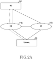
- FIG. 2A is a diagram illustrating an example of a 5G NSA system.
- the 5G NSA system includes an NR RAN 210a, an LTE RAN 210b, a terminal 220, and an evolved packet core (EPC) 250.
- the NR RAN 210a and the LTE RAN 210b may be connected to the EPC 150, and the terminal 220 may receive a service concurrently from any one of the NR RAN 210a and the LTE RAN 210b or the both.
- the NR RAN 210a includes at least one NR base station
- the LTE RAN 210b includes at least one LTE base station.
- the NR base station may be denoted as a '5 th generation (5G) node', a 'next generation nodeB (gNB)' or other terms having a technological meaning equivalent to these.
- the NR base station may have a structure separated into a central unit (CU) and a digital unit (DU), and also the CU may have a structure separated into a CU - control plane (CP) unit and a CU - user plane (UP) unit.
- CU central unit
- DU digital unit
- CP CU - control plane
- UP CU - user plane
- the terminal 220 may perform radio resource control (RRC) access through a first base station (example: a base station belonging to the LTE RAN 210b), and receive a service of a function (example: connection management, mobility management, etc.) presented by a control plane. Also, the terminal 220 may receive an additional wireless resource for transceiving data through a second base station (example: a base station belonging to the NR RAN 210a).
- RRC radio resource control
- a first base station example: a base station belonging to the LTE RAN 210b
- a service of a function example: connection management, mobility management, etc.
- the terminal 220 may receive an additional wireless resource for transceiving data through a second base station (example: a base station belonging to the NR RAN 210a).
- a dual connectivity technology using these LTE and NR may be denoted as evolved universal terrestrial radio access (E-UTRA) - NR dual connectivity (EN-DC).
- NR - E- UTRA dual connectivity NE - DC
- various embodiments may be applied to multiple connectivity and carrier aggregation technologies of various forms besides this. Also, various embodiments may be applied even to when a first system using a first communication technology and a second system using a second communication technology are implemented in one apparatus or when the first base station and the second base station are located in the same geographical position.
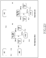
- FIG. 2B is a diagram illustrating an example of an architecture for an O-RAN. It may be assumed that, for the purpose of key performance indicator (KPI) monitoring (E2-SM-KPIMON) of an E2 service model, an O-RAN non-stand alone mode in a multi-connectivity operation using an E-UTRA and NR radio access technology is considered, while an E2 node is in an O-RAN stand alone mode.
- KPI key performance indicator
- E2-SM-KPIMON key performance indicator monitoring
- an eNB in the deployment of the O-RAN non-stand alone mode, may be connected to an EPC through an S1 - C / S1 - U interface, and may be connected to an O-CU-CP through an X2 interface.
- an O-CU-CP In the deployment of the O-RAN stand alone mode, an O-CU-CP may be connected to a 5G core (5GC) through an N2 / N3 interface.
- 5GC 5G core
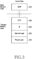
- FIG. 3 is a diagram illustrating an example protocol stack of an E2 application protocol message in a radio access network according to various embodiments.
- a control plane includes a transport network layer and a radio network layer.
- the transport network layer includes a physical layer 310, a data link layer 320, an Internet protocol (IP) 330, and a stream control transmission protocol (SCTP) 340.
- IP Internet protocol
- SCTP stream control transmission protocol
- the radio network layer includes an E2AP 350.
- the E2AP 350 is used to forward a subscription message, an indication message, a control message, a service update message, a service query message, and is transmitted over the SCTP 340 and the IP 330.
- FIG. 4 is a diagram illustrating an example of connection between a base station and a radio access network intelligence controller (RIC) in a radio access network according to various embodiments.
- RIC radio access network intelligence controller
- the RIC 440 is connected with an O-CU-CP 420, an O-CU-UP 410, and an O-DU 430.
- the RIC 440 is a apparatus for customizing an RAN functionality for new service or regional resource optimization.
- the RIC 440 may present a function of network intelligence (example: policy enforcement and handover optimization), resource assurance (example: radio-link management and advanced self-organized-network (SON)), resource control (example: load balancing and slicing policy), etc.
- the RIC 440 may perform communication with the O-CU-CP 420, the O-CU-UP 410, and the O-DU 430.
- the RIC 440 is possible to connect with each node by an E2-CP, E2-UP, or E2-DU interface.
- an interface between the O-CU-CP and the DU and/or between the O-CU-UP and the DU may be called an F1 interface.
- the DU and the O-DU, the CU-CP and the O-CU-CP, or the CU-UP and the O-CU-UP may be used interchangeably.
- FIG. 4 an embodiment of one RIC 440 is illustrated, but in accordance with various embodiments, a plurality of RICs may exist.
- the plurality of RICs may be implemented in a plurality of hardware located in the same physical position or be implemented through virtualization using one hardware.
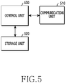
- FIG. 5 is a block diagram illustrating an example configuration of an network entity according to various embodiments.
- An embodiment of structure illustrated in FIG. 5 may be understood as a construction of an network entity having a function of at least one of the RIC, the O-CU-CP, the O-CU-UP, and the O-DU of FIG. 5 .
- the terms '...unit', '...er', etc. used below may refer, for example, the unit of processing at least one function or operation. This may be implemented in hardware or software, or a combination of hardware and software.
- a core network entity includes a communication unit 510, a storage unit 520, and a control unit 530.
- the communication unit 510 presents an interface for performing communication with other entities within a network.
- the communication unit 510 converts a bit string transmitted from the core network entity to other entities into a physical signal, and converts a physical signal received from other entities into a bit string.
- the communication unit 510 may transmit and receive a signal.
- the communication unit 510 may be called a modem, a transmitter, a receiver, or a transceiver.
- the communication unit 510 may enable the core network entity to communicate with other entities or a system via backhaul connection (example: wired backhaul or wireless backhaul) or via a network.
- the storage unit 520 stores data such as a basic program for an operation of the core network entity, an application program, setup information, etc.
- the storage unit 520 may be comprised of a volatile memory, a non-volatile memory, or a combination of the volatile memory and the non-volatile memory. And, the storage unit 520 presents the stored data in accordance with a request of the control unit 530.
- the control unit 530 controls general operations of the core network entity.
- the control unit 530 transceives a signal through the communication unit 510.
- the control unit 530 records data in the storage unit 520, and reads.
- the control unit 530 may include at least one processor.
- the control unit 530 may control the network entity to perform operations of various embodiments described in the present disclosure.
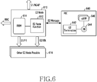
- FIG. 6 is a diagram illustrating a logical function related to an E2 message of an E2 node and an RIC in a radio access network according to various embodiments.
- the RIC 640 and the E2 node 610 may transmit or receive an E2 message therebetween.
- the E2 node 610 may be an O-CU-CP, an O-CU-UP, an O-DU, or a base station.
- a communication interface of the E2 node may be determined according to the type of the E2 node 610.
- the E2 node 610 may perform communication with another E2 node 616 through an E1 interface or an F1 interface.
- the E2 node 610 may perform communication with the E2 node 616 through an X2 interface or an XN interface.
- the E2 node 610 may perform communication through an S1 interface or a next generation application protocol (NGAP) interface (e.g., an interface between a next generation (NG) RAN node and an AMF).
- NGAP next generation application protocol
- the E2 node 610 includes an E2 node function 612.
- the E2 node function 612 is a function corresponding to a specific application S/W (xApp) 646 installed in the RIC 640.
- a KPI monitor collection S/W may be installed in the RIC 540, and the E2 node 610 may include an E2 node function 612 of providing KPI parameters and then forwarding an E2 message including the KPI parameter to an E2 termination function 642 located in the RIC 640.
- the E2 node 610 may manage resources presented to a wireless network for a terminal.
- the E2 termination function 642 located in the RIC 640 is a termination of the RIC 640 for the E2 message, and performs a function of interpreting the E2 message forwarded by the E2 node 610 and then forwarding to the xApp 646.
- a database (DB) 644 located in the RIC 640 may be used for the E2 termination 624 or the xApp 616.
- the E2 node 610 illustrated in FIG. 6 is a termination of at least one interface, and may be understood as a termination of messages forwarded to a terminal, a peripheral base station, and/or a core network.
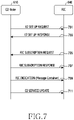
- FIG. 7 is a signal flow diagram illustrating an example procedure for setup of E2 I/F between an E2 node and an RIC, RIC subscription, and information presentation in a radio access network according to various embodiments.
- the E2 node 610 transmits an E2 setup request message to the RIC 640.
- an E2 node function located in the E2 node 610 searches for the RIC 640 using an IP address of the RIC 640 set up by operation-administration-maintenance (OAM) and transmits the E2 setup request message.
- the E2 setup request message may include an RAN function capability information element (IE) (e.g., RAN FUNCTION DEFINITION) supported by the E2 node 610, an E2 node ID, and the like.
- IE RAN function capability information element
- a value of the RAN FUNCTION DEFINITION is a value set up by OAM and may include an RIC STYLE ID value.
- the RIC 640 may receive the RAN FUNCTION DEFINITION value through the E2 setup message or an E2 service update message, and may identify which call processing function is supported by the E2 node 610, based on the RAN FUNCTION DEFINITION value.
- the RIC 640 transmits an E2 SETUP RESPONSE message to the E2 node 610. For example, when the E2 setup request message transmitted by the E2 node 610 is acceptable, the RIC 640 transmits the E2 setup response message.
- the RIC 640 transmits an RIC SUBSCRIPTION REQUEST message to the E2 node 610.
- a specific xApp located in the RIC 640 requests an RIC E2 termination function to subscribe to a specific E2 RAN FUNCTION DEFINITION function supported by E2.
- the E2 RAN FUNCTION DEFINITION may be a service model (SM) defined specifically for an operator, and whether an operator is specific may be indicated using an RIC STYLE ID. Whether the operator is specified may be indicated by an IE other than the RIC STYLE ID.
- the RIC subscription request message may be included in the E2 setup response message transmitted in operation 703.
- the E2 node 610 transmits an RIC SUBSCRIPTION RESPONSE message to the RIC 640.
- the E2 node function of the E2 node 610 decodes the RIC subscription request message and configures an event condition that the RIC 640 has requested to the E2 node function.
- the event condition may be a service model specifically defined by the operator as RAN FUNCTION DEFINITION, and whether the operator is specific may be specified by the RIC STYLE ID.
- the E2 node 610 may notify the RIC 640 that an event trigger condition is successfully configured, by transmitting the RIC subscription response message.
- the E2 node 610 transmits an RIC INDICATION to the RIC 640.
- the E2 node 610 transmits an E2 RIC indication message to the RIC 640.
- the RIC indication may be a message container.
- the RIC indication message may be a service model specifically defined by the operator, and whether the user is specific may be specified by the RIC STYLE ID.
- the E2 node 610 transmits an E2 service update message to the RIC 640.
- the E2 node 610 transmits the changed RAN FUNCTION DEFINITION using the E2 service update message.
- FIG. 8 is a signal flow diagram illustrating an example procedure for E2 RIC control between an E2 node and an RIC in a radio access network according to various embodiments.
- the E2 node 610 and the RIC 640 perform an E2 setup procedure.
- An E2 node function located in the E2 node 610 may find the RIC 640 using an IP address of the RIC 640 set up by OAM, and then transmit an E2 setup request message, thereby notifying which call processing function is supported by the E2 node 610.
- the RIC 640 may transmit an E2 setup response message to the E2 node 610.
- the RIC 640 transmits an RIC SUBSCRIPTION REQUEST message to the E2 node 610.
- a specific xApp located in the RIC 640 requests an RIC E2 termination function to subscribe to a specific E2 RAN FUNCTION DEFINITION function supported by E2.
- the E2 RAN FUNCTION DEFINITION may be a service model (SM) defined specifically for an operator, and whether the operator is specific may be indicated using an RIC STYLE ID. Whether the operator is specified may be indicated by an IE other than the RIC STYLE ID.
- the RIC subscription request message may be included in the E2 setup response message transmitted in operation 703.
- an operator-specific subscription may be configured using an RIC event trigger definition.
- the E2 node 610 transmits an E2 subscription response message to the RIC 640.
- the E2 node 610 may notify a success or non-success of the operator-specific subscription to the RIC 640 by transmitting the subscription response message.
- the E2 node 610 transmits an RIC INDICATION to the RIC 640.
- the E2 node function of the E2 node 610 forwards an E2 RIC indication message to the RIC 640.
- the RIC indication may be a message container.
- the E2 indication message may be transmitted in an operator-specific message type. According to an embodiment, whether the operator-specific message is may be indicated by an RIC INDICATION HEADER TYPE, an RIC INDICATION MESSAGE TYPE, or an RIC STYLE ID.
- the RIC 640 transmits an E2 CONTROL REQUEST message to the E2 node 610.
- the RIC 640 may control the event occurring in operation 807, by transmitting the E2 control request message to the E2 node function.
- the E2 control message may be transmitted in an operator-specific message type. According to an embodiment, whether the operator-specific message is may be indicated by an RIC CONTROL HEADER TYPE, an RIC CONTROL MESSAGE TYPE, or an RIC STYLE ID.
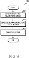
- FIG. 9 is a flowchart 900 illustrating an example operation of providing and transmitting an E2 message in a radio access network according to various embodiments.
- FIG. 9 illustrates an operation method of an E2 node or an RIC. Since the E2 message may be transmitted by the E2 node or the RIC, an operating subject of the flowchart 900 of FIG. 9 below may be understood as the E2 node or the RIC. For convenience, the operating subject of the flowchart 900 of FIG. 9 is referred to as a 'apparatus'.
- the apparatus provides or generates information related to an RIC service.
- the service may be related to an operation for supporting a radio access performed in the E2 node.
- the service may be related to operations such as call processing, call connection, call acceptance determination, handover, carrier aggregation, dual connectivity, and the like.
- the information related to the RIC service may follow a format defined in the standard or may follow an operator-specific format.
- the apparatus provides or generates information indicating a message type.
- the message type corresponds to the RIC service corresponding to the information provided in operation 901.
- a value of the information indicating the message type may belong to a first range when the information related to the RIC service follows the format defined in the standard, and may belong to a second range when the information related to the RIC service does not follow the format defined in the standard.
- the second range is a range including values allocated for a service specifically defined by an operator.
- the apparatus transmits an E2 message.
- the apparatus provides the E2 message including the information provided in operation 901 and the information provided in operation 903, and transmits the provided E2 message.
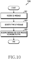
- FIG. 10 is a flowchart 1000 illustrating an example operation of receiving and interpreting an E2 message in a radio access network according to various embodiments.
- FIG. 10 illustrates an operation method of an E2 node or an RIC. Since the E2 message may be transmitted by the E2 node or the RIC, an operating subject of the flowchart 1000 of FIG. 10 below may be understood as the E2 node or the RIC. For convenience, the operating subject of the flowchart 1000 of FIG. 10 is referred to as a 'apparatus'.
- the apparatus receives an E2 message.
- the E2 message may include information related to an RIC service and information indicating the type of the message.
- the apparatus identify the type of the message.
- the message includes information indicating the type.
- the information indicating the type may be included in a fixed position regardless of whether a format of the message has been defined as operator-specific.
- the apparatus may confirm that the received E2 message follows one of the formats defined in the standard.
- the apparatus may confirm that the received E2 message does not follow one of the formats defined in the standard, but follows the format defined specifically by the operator.
- the second range is a range including values allocated for an operator-specifically defined service.
- the apparatus acquires information from the message according to the type.
- the apparatus may analyze the received E2 message, based on one of the formats defined in the standard, and acquire the information related to the RIC service.
- the apparatus may analyze the E2 message, based on the received operator-specifically defined format, and acquire the information related to the RIC service.
- various E2 messages may be used for procedures performed between the E2 node and the RIC.
- a service model defined in the standard not a service model defined in the standard, but a service model specifically defined for an operator may be used.
- a message related to the corresponding service model follows a structure or format defined by the corresponding operator.
- information or an indicator for notifying that the structure or format of the message is defined by the operator may be included in the message.
- various messages including the information or indicator for notifying that the structure or format of the message is defined by the operator may be defined as shown in [Table 1] to [Table 9] below.
- Table 1 is an example of an RIC EVENT TRIGGER DEFINITION IE included in the E2 subscription request message.
- an RIC EVENT TRIGGER DEFINITION TYPE field may be defined, and through this, a maximum of 256 RIC EVENT TRIGGERs may be defined, and values of sections 129 to 256 among the 256 types may be defined by an operator, thereby being used as an out-of-standard method.
- the RIC EVENT TRIGGER DEFINITION TYPE field is defined as one of 129 to 256
- the remaining fields included in the RIC EVENT TRIGGER DEFINITION IE may be configured specifically for an operator.
- RIC EVENT TRIGGER DEFINITION TYPE field illustrated in Table 1 may be omitted, and at least one other field may be added.
- the newly added field may be a field not defined in the standard, and the setup and interpretation of the value may follow the operator-specific rules.
- IE/Group Name Presence Range IE type and reference Semantics description RIC ACITION DEFINITION TYPE M 0.. ⁇ maxofType> Type number 129 ⁇ 256 is reserved for the operator-specific use.
- Table 2 is an example of an RIC ACTION DEFINITION IE included in the E2 subscription request message.
- an RIC ACTION DEFINITION TYPE field may be defined, and through this, a maximum of 256 RIC ACTION DEFINITIONs maybe defined, and values of sections 129 to 256 among the 256 types may be defined by the operator, thereby being used as an out-of-standard method.
- the RIC ACTION DEFINITION TYPE field is defined as one of 129 to 256, the remaining fields included in the RIC ACTION DEFINITION IE may be configured specifically for the operator.
- RIC ACTION DEFINITION TYPE field illustrated in Table 2 may be omitted, and at least one other field may be added.
- the newly added field may be a field not defined in the standard, and the setup and interpretation of the value may follow the operator-specific rules.
- IE/Group Name Presence Range IE type and reference Semantics description RIC INDICATION HEADER TYPE M 0.. ⁇ maxofType> Type number 129 ⁇ 256 is reserved for the operator-specific use.
- Table 3 is an example of an RIC INDICATION HEADER IE included in the E2 indication message.
- an RIC INDICATION HEADER TYPE field may be defined, and through this, a maximum of 256 RIC INDICATION HEADERs may be defined, and values of sections 129 to 256 among 256 types may be defined by the operator, thereby being used as an out-of-standard method.
- the RIC INDICATION HEADER TYPE field is defined as one of 129 to 256, the remaining fields included in the RIC INDICATION HEADER IE may be configured specifically for the operator.
- At least one of the remaining fields other than the RIC INDICATION HEADER TYPE field illustrated in Table 3 may be omitted, and at least one other field may be added.
- the newly added field may be a field not defined in the standard, and the setup and interpretation of the value may follow the operator-specific rules.
- [Table 4] IE/Group Name Presence Range IE type and reference Semantics description RIC INDICATION MESSAGE TYPE M 0.. ⁇ maxofType> Type number 129 ⁇ 256 is reserved for the operator-specific use.
- Table 4 is an example of an RIC INDICATION MESSAGE IE included in the E2 indication message.
- an RIC INDICATION MESSAGE TYPE field may be defined, and through this, a maximum of 256 RIC INDICATION MESSAGEs may be defined, and values of sections 129 to 256 among 256 types may be defined by the operator, thereby being used as an out-of-standard method.
- the RIC INDICATION MESSAGE TYPE field is defined as one of 129 to 256, the remaining fields included in the RIC INDICATION MESSAGE IE may be configured specifically for the operator.
- RIC INDICATION MESSAGE TYPE field illustrated in Table 4 may be omitted, and at least one other field may be added.
- the newly added field may be a field not defined in the standard, and the setup and interpretation of the value may follow the operator-specific rules.
- IE/Group Name Presence Range IE type and reference Semantics description RIC CONTROL HEADER TYPE M 0.. ⁇ maxofType> Type number 129 ⁇ 256 is reserved for the operator-specific use.
- Table 5 is an example of an RIC CONTROL HEADER IE included in the E2 control message.
- an RIC CONTROL HEADER TYPE field may be defined, and through this, a maximum of 256 RIC CONTROL HEADERs may be defined, and values of sections 129 to 256 among the 256 types may be defined by the operator, thereby being used as an out-of-standard method.
- the RIC CONTROL HEADER TYPE field is defined as one of 129 to 256, the remaining fields included in the RIC CONTROL HEADER IE may be configured specifically for the operator.
- At least one of the remaining fields other than the RIC CONTROL HEADER TYPE field illustrated in Table 5 may be omitted, and at least one other field may be added.
- the newly added field may be a field not defined in the standard, and the setup and interpretation of the value may follow the operator-specific rules.
- IE/Group Name Presence Range IE type and reference Semantics description RIC CONTROL MESSAGE TYPE M 0.. ⁇ maxofType> Type number 129 ⁇ 256 is reserved for the operator-specific use.
- Table 6 is an example of an RIC CONTROL MESSAGE IE included in the E2 control message.
- an RIC CONTROL MESSAGE TYPE field may be defined, and through this, a maximum of 256 RIC CONTROL MESSAGEs may be defined, and values of sections 129 to 256 among the 256 types may be defined by the operator, thereby being used as an out-of-standard method.
- the RIC CONTROL MESSAGE TYPE field is defined as one of 129 to 256, the remaining fields included in the RIC CONTROL MESSAGE IE may be configured specifically for the operator.
- At least one of the remaining fields other than the RIC CONTROL MESSAGE TYPE field illustrated in Table 6 may be omitted, and at least one other field may be added.
- the newly added field may be a field not defined in the standard, and the setup and interpretation of the value may follow the operator-specific rules.
- [Table 7] IE/Group Name Presence Range IE type and reference Semantics description RIC CALL PROCESS ID TYPE M 0.. ⁇ maxofType> Type number 129 ⁇ 256 is reserved for the operator-specific use. RAN Call process ID type 1 M 8.3.10
- Table 7 is an example of an RIC CALL PROCESS ID IE included in the E2 control message.
- an RIC CALL PROCESS ID TYPE field may be defined, and through this, a maximum of 256 RIC CALL PROCESS IDs may be defined, and values of sections 129 to 256 among the 256 types may be defined by the operator, thereby being used as an out-of-standard method.
- the RIC CALL PROCESS ID TYPE field is defined as one of 129 to 256, the remaining fields included in the RIC CALL PROCESS ID IE may be configured specifically for the operator.
- At least one of the remaining fields other than the RIC CALL PROCESS ID TYPE field illustrated in Table 7 may be omitted, and at least one other field may be added.
- the newly added field may be a field not defined in the standard, and the setup and interpretation of the value may follow the operator-specific rules.
- [Table 8] IE/Group Name Presence Range IE type and reference Semantics description RAN FUNCTION DEFINITION TYPE M 0.. ⁇ maxofType> Type number 129 ⁇ 256 is reserved for the operator-specific use.
- ⁇ maxofActionParameters> >>RIC Parameter ID M 8.3.6 >>RIC Parameter Name M 8.3.9 >>RIC Parameter Type M 8.3.5 Sequence of Control styles 0..
- ⁇ maxofStyle> >RIC Style ID M 8.3.3 >RIC Style Name M 8.3.4 >Sequence of parameters 0..
- ⁇ maxofActionParameters> >>RIC Parameter ID M 8.3.6 >>RIC Parameter Name M 8.3.9 >>RIC Parameter Type M 8.3.5 Sequence of Policy styles 0..
- ⁇ maxofActionParameters> parameters >>RIC Parameter ID M 8.3.6 >>RIC Parameter Name M 8.3.9 >>RIC Parameter Type M 8.3.5
- Table 8 is an example of an RAN FUNCTION DEFINITION IE included in the E2 service update message.
- an RAN FUNCTION DEFINITION TYPE field may be defined, and through this, a maximum of 256 RAN FUNCTION DEFINITION TYPEs may be defined, and values of sections 129 to 256 among the 256 types may be defined by the operator, thereby being used as an out-of-standard method.
- the RAN FUNCTION DEFINITION TYPE field is defined as one of 129 to 256
- the remaining fields included in the RAN FUNCTION DEFINITION IE may be configured specifically for the operator.
- At least one of the remaining fields other than the RAN FUNCTION DEFINITION TYPE field illustrated in Table 8 may be omitted, and at least one other field may be added.
- the newly added field may be a field not defined in the standard, and the setup and interpretation of the value may follow the operator-specific rules.
- IE/Group Name Presence Range IE type and reference Semantics description RIC style ID M INTEGER (1 ⁇ 256) 129 ⁇ 256 is reserved for the operator-specific style ID.
- Table 9 is an example of an RIC STYLE ID.
- the RIC STYLE ID defined in the conventional O-RAN was available only for an E2 service model defined in the standard.
- the RIC STYLE ID of Table 9 defines a range of 128 to 256 as a range for an operator-specific use, and enables the definition and use of a specific operator or operator's unique function.
- the RIC STYLE ID of Table 9 may indicate an operator-specific service model by replacing, or being used in parallel with, various TYPE fields of Table 1 to Table 8 described above.
- values of 129 to 256 among values of a type field or style ID field were allocated for an operator-specific message.
- a range of the values of the type field or style ID field for the operator-specific message may vary.
- the values for the operator-specific message may be defined as discontinuous values rather than continuous values.
- values corresponding to multiples of a specific number are assigned as values for operator-specific messages, or values having a least significance bit (LSB) of a specific value or a most significant bit (MBS) of a specific value when expressed in binary or hexadecimal may be assigned as the values for the operator-specific messages.
- E2SM operator-specific E2SM
- examples of operator-specific E2SM are as follows.
- the vendor may set the type of an E2SM function illustrated by way of non-limiting example below as an operator-specific type.
- a corresponding relationship between each E2SM function and a message is shown in [Table 10] below.
- an E2 node may use POLICY, CONTROL, and REPORT among POLICY, CONTROL, REPORT, and INSERT services specified in the O-RAN standard.
- the E2 node may forward the operator-specific E2SM function supported by the E2 node, to the RIC, using the RAN FUNCTION DESCRIPTION defined in [Table 8] in the E2 interface setting operation.
- the E2 node may set an RAN Function Definition Type defined in [Table 11] below, by a value (e.g., 129) assigned as the operator-specific type.
- the E2 node or the RIC may set an actual RIC parameter value of the E2SM by a parameter desired by the operator.
- the E2 node or the RIC may set a desired RIC parameter value by a value desired by the operator, and may set an RAN function name.
- POLICY SERVICE is forwarded from the RIC to the E2 node through an E2AP subscription message.
- the E2AP subscription message forwards the RIC Event Trigger Definition of Table 1.
- the RIC Event Trigger Definition is set as a value indicating a subscriber specific type.
- an RIC EVENT TRIGGER DEFINITION TYPE value may be set as 129
- an RIC Style ID value may be set as 1
- an RIC Parameter Type may be set as Integer
- a Sequence of Trigger Conditions may be set as RIC Parameter ID (NSSAI) is equal to '100'.
- NSSAI RIC Parameter ID
- E2-SM-IE is a value presented by the E2 node that is actually required by the operator, and is possible to set all values such as a value standardized in the standard or a value non-standardized in the standard, etc.
- IE/Group Name Presence Range IE type and reference Semantics description RIC EVENT TRIGGER DEFINITION TYPE M 1.. ⁇ maxofTy pe> Type number 129 ⁇ 256 is reserved for the operator-specific use.
- a CommonRadioResourceUsage value is a value non-standardized in the current 3GPP standard.
- the E2 node having performed a non-standard operation desired by the operator may report the execution result of a non-standard function to the RIC using an RIC indication message (e.g., Table 4) and an RIC indication header (e.g., Table 3).
- a value of an RIC INDICATION HEADER TYPE is set as a value (e.g., 129) allocated for operator-specific information, and an updated value of a value of Table 13 is forwarded.
- a value of an RIC INDICATION MESSAGE Type is set as a value (e.g., 129) allocated for the operator-specific information, and the E2 node forwards a non-standard message to the RIC using an RAN container.
- a method for operating a apparatus which uses an interface between a radio access network intelligent controller (RIC) and a node including a base station in a radio access network may include: providing first information related with an RIC service, providing second information indicating the type of a message to be used for transmitting the first information, and transmitting the message including the first information and the second information.
- RIC radio access network intelligent controller
- the type of the message may be determined according to the RIC service related to the first information.
- the type of the message may correspond to a format of the first information.
- the type of the message may belong to a first range including values for indicating a message format defined in the standard, or belong to a second range including values for indicating a message format defined for an operator.
- the node including the base station may be one of a digital unit (DU), a central unit (CU) - control plane (CP), and a CU - user plane (UP).
- DU digital unit
- CU central unit
- CP central unit
- UP CU - user plane
- a method for operating a apparatus which uses an interface between a radio access network intelligent controller (RIC) and a node including a base station in a radio access network may include: receiving a message including first information related to an RIC service, identifying the type of the message, based on second information indicating the type of the message included in the message, and acquiring the first information, based on the second information.
- RIC radio access network intelligent controller
- the type of the message may be determined according to the RIC service related to the first information.
- the type of the message may correspond to a format of the first information.
- the type of the message may belong to a first range including values for indicating a message format defined in the standard, or belong to a second range including values for indicating a message format defined for an operator.
- the node including the base station may be one of a digital unit (DU), a central unit (CU) - control plane (CP), and a CU - user plane (UP).
- DU digital unit
- CU central unit
- CP central unit
- UP CU - user plane
- a apparatus configured to use an interface between a radio access network intelligent controller (RIC) and a node including a base station in a radio access network may include a transceiver, and at least one processor connected to the transceiver.
- the at least one processor may be configured to control the apparatus to: provide first information related to an RIC service, provide second information indicating the type of a message to be used for forwarding the first information, and transmit the message including the first information and the second information.
- the type of the message may be determined according to the RIC service related to the first information.
- the type of the message may correspond to a format of the first information.
- the type of the message may belong to a first range including values for indicating a message format defined in the standard, or belong to a second range including values for indicating a message format defined for an operator.
- the node including the base station may be one of a digital unit (DU), a central unit (CU) - control plane (CP), and a CU - user plane (UP).
- DU digital unit
- CU central unit
- CP central unit
- UP CU - user plane
- a apparatus configured to use an interface between a radio access network intelligent controller (RIC) and a node including a base station in a radio access network may include a transceiver, and at least one processor connected to the transceiver.
- the at least one processor may be configured to control the apparatus to: receive a message including first information related to an RIC service, identify the type of the message, based on second information indicating the type of the message included in the message, and acquire the first information, based on the second information.
- the type of the message may be determined according to the RIC service related to the first information.
- the type of the message may correspond to a format of the first information.
- the type of the message may belong to a first range including values for indicating a message format defined in the standard, or belong to a second range including values for indicating a message format defined for an operator.
- the node including the base station may be one of a digital unit (DU), a central unit (CU) - control plane (CP), and a CU - user plane (UP).
- DU digital unit
- CU central unit
- CP central unit
- UP CU - user plane
- a non-transitory computer-readable storage medium storing one or more programs (e.g., software modules) may be presented.
- One or more programs stored in the computer-readable storage medium are configured to be executable by one or more processors in an electronic device.
- One or more programs include instructions for enabling the electronic device to execute the methods of embodiments described in claims or specification of the present disclosure.
- These programs may be stored in a random access memory, a non-volatile memory including a flash memory, a read only memory (ROM), an electrically erasable programmable ROM (EEPROM), a magnetic disc storage device, a compact disc-ROM (CD-ROM), digital versatile discs (DVDs), or an optical storage device of other forms, and/or a magnetic cassette. Or, they may be stored in a memory including a combination of some or all thereof. Also, each configuration memory may be included in plurality as well.
- the program may be stored in an attachable storage device that may be accessed through a communication network such as the Internet, an intranet, a local area network (LAN), a wide area network (WAN), or a storage area network (SAN), or a communication network including a combination thereof.
- a communication network such as the Internet, an intranet, a local area network (LAN), a wide area network (WAN), or a storage area network (SAN), or a communication network including a combination thereof.
- This storage device may be connected to a device performing an embodiment of the present disclosure through an external port.
- a separate storage device on the communication network may be connected to a device performing an embodiment of the present disclosure as well.
Landscapes
- Engineering & Computer Science (AREA)
- Computer Networks & Wireless Communication (AREA)
- Signal Processing (AREA)
- Mobile Radio Communication Systems (AREA)
Applications Claiming Priority (2)
| Application Number | Priority Date | Filing Date | Title |
|---|---|---|---|
| KR1020190151746A KR20210063168A (ko) | 2019-11-22 | 2019-11-22 | 무선 접속 망에서 사업자 특정 서비스를 지원하기 위한 장치 및 방법 |
| PCT/KR2020/016621 WO2021101355A1 (ko) | 2019-11-22 | 2020-11-23 | 무선 접속 망에서 운영자 특정 서비스를 지원하기 위한 장치 및 방법 |
Publications (2)
| Publication Number | Publication Date |
|---|---|
| EP4050967A1 true EP4050967A1 (de) | 2022-08-31 |
| EP4050967A4 EP4050967A4 (de) | 2022-12-28 |
Family
ID=75981426
Family Applications (1)
| Application Number | Title | Priority Date | Filing Date |
|---|---|---|---|
| EP20890192.6A Pending EP4050967A4 (de) | 2019-11-22 | 2020-11-23 | Gerät und verfahren zum unterstützen eines betreiberspezifischen dienstes in einem drahtlosen zugangsnetz |
Country Status (4)
| Country | Link |
|---|---|
| US (1) | US12477540B2 (de) |
| EP (1) | EP4050967A4 (de) |
| KR (1) | KR20210063168A (de) |
| WO (1) | WO2021101355A1 (de) |
Cited By (3)
| Publication number | Priority date | Publication date | Assignee | Title |
|---|---|---|---|---|
| US20220279498A1 (en) * | 2019-11-22 | 2022-09-01 | Samsung Electronics Co., Ltd. | Apparatus and method for supporting operator-specific service in wireless access network |
| EP4080931A4 (de) * | 2019-12-17 | 2023-02-01 | Samsung Electronics Co., Ltd. | Verfahren und vorrichtung zum messen der leistung in einem drahtlosen kommunikationssystem |
| EP4346269A1 (de) * | 2022-09-28 | 2024-04-03 | Nokia Solutions and Networks Oy | Verfahren zur prüfung von dienstabonnements |
Families Citing this family (7)
| Publication number | Priority date | Publication date | Assignee | Title |
|---|---|---|---|---|
| US11337131B1 (en) * | 2020-12-31 | 2022-05-17 | Sterlite Technologies Limited | Method and apparatus for recommending real-time handover to a target cell in open-radio access network (O-RAN) environment |
| KR20230027447A (ko) * | 2021-08-19 | 2023-02-28 | 삼성전자주식회사 | E2 종단의 트래픽 정보에 기반하여 e2 종단을 제어하는 전자 장치 및 전자 장치의 동작 방법 |
| EP4362544B1 (de) | 2021-08-19 | 2025-08-20 | Samsung Electronics Co., Ltd. | Elektronische vorrichtung zur steuerung des e2-abschlusses auf basis von verkehrsinformationen des e2-abschlusses und verfahren zum betrieb der elektronischen vorrichtung |
| CN116033444B (zh) * | 2021-10-25 | 2025-10-17 | 大唐移动通信设备有限公司 | 一种网络集成控制方法及装置 |
| CN116669066B (zh) * | 2022-02-28 | 2026-03-17 | 诺基亚通信公司 | 小区站点辅助设备控制 |
| KR20230152520A (ko) * | 2022-04-27 | 2023-11-03 | 삼성전자주식회사 | 무선 액세스 네트워크에서 셀 관리를 위한 장치 및 방법 |
| EP4503736A4 (de) | 2022-04-27 | 2025-07-23 | Samsung Electronics Co Ltd | Vorrichtung und verfahren zur zellenverwaltung in einem drahtlosen zugangsnetzwerk |
Family Cites Families (17)
| Publication number | Priority date | Publication date | Assignee | Title |
|---|---|---|---|---|
| US6049545A (en) * | 1997-10-03 | 2000-04-11 | Alcatel Usa Sourcing, L.P. | System and method for message communications in a distributed telecommunications switch |
| KR100449032B1 (ko) * | 2002-08-21 | 2004-09-16 | 삼성전자주식회사 | 홈네트워크 원격 관리 시스템의 엔티티간 데이터 송수신방법 |
| US7983676B2 (en) * | 2004-03-10 | 2011-07-19 | Sk Telecom Co., Ltd. | Inter-system handover |
| US8725122B2 (en) * | 2009-05-13 | 2014-05-13 | First Data Corporation | Systems and methods for providing trusted service management services |
| CN102577227A (zh) | 2010-05-31 | 2012-07-11 | 三洋电机株式会社 | 终端装置以及基站装置 |
| US10469506B2 (en) * | 2012-07-19 | 2019-11-05 | Tecore, Inc. | Systems and methods for communication control in a restricted environment |
| US20160149779A1 (en) * | 2013-05-27 | 2016-05-26 | Rangaprasad Sampath | System state message in software defined networking |
| US20160162858A1 (en) * | 2014-12-04 | 2016-06-09 | Verance Corporation | Screening architectures enabling revocation and update |
| KR102275579B1 (ko) | 2014-12-22 | 2021-07-09 | 삼성전자 주식회사 | 이동 통신 시스템에서 전송 차별화를 제공하는 방법 및 장치 |
| KR102857556B1 (ko) | 2019-01-22 | 2025-09-09 | 삼성전자주식회사 | 무선 통신 시스템에서 네트워크 슬라이스의 인터워킹을 제공하기 위한 장치 및 방법 |
| WO2020153773A1 (en) | 2019-01-22 | 2020-07-30 | Samsung Electronics Co., Ltd. | Device and method for providing network slice interworking in wireless communication system |
| KR20200111099A (ko) | 2019-03-18 | 2020-09-28 | 한국전자통신연구원 | 기능 분리를 지원하는 통신 시스템에서 데이터의 송수신을 위한 방법 및 장치 |
| US20210051567A1 (en) * | 2019-08-15 | 2021-02-18 | Qualcomm Incorporated | Radio access network feature set extension in medium access control |
| JP7695040B2 (ja) * | 2019-10-01 | 2025-06-18 | サムスン エレクトロニクス カンパニー リミテッド | 無線アクセスネットワーク通信システムにおけるe2インタフェースを介するサービス加入のための装置及び方法 |
| KR20210063168A (ko) * | 2019-11-22 | 2021-06-01 | 삼성전자주식회사 | 무선 접속 망에서 사업자 특정 서비스를 지원하기 위한 장치 및 방법 |
| US12376142B2 (en) * | 2022-08-19 | 2025-07-29 | Qualcomm Incorporated | Methods for enhanced sidelink communications with clustered or peer-to-peer federated learning |
| CN119452688A (zh) * | 2022-10-05 | 2025-02-14 | 乐天移动株式会社 | 用于在电信网络内实现o1相关服务的r1-o1数据模型的装置和方法 |
-
2019
- 2019-11-22 KR KR1020190151746A patent/KR20210063168A/ko active Pending
-
2020
- 2020-11-23 WO PCT/KR2020/016621 patent/WO2021101355A1/ko not_active Ceased
- 2020-11-23 EP EP20890192.6A patent/EP4050967A4/de active Pending
-
2022
- 2022-05-20 US US17/749,978 patent/US12477540B2/en active Active
Cited By (6)
| Publication number | Priority date | Publication date | Assignee | Title |
|---|---|---|---|---|
| US20220279498A1 (en) * | 2019-11-22 | 2022-09-01 | Samsung Electronics Co., Ltd. | Apparatus and method for supporting operator-specific service in wireless access network |
| US12477540B2 (en) * | 2019-11-22 | 2025-11-18 | Samsung Electronics Co., Ltd. | Apparatus and method for supporting operator-specific service in wireless access network |
| EP4080931A4 (de) * | 2019-12-17 | 2023-02-01 | Samsung Electronics Co., Ltd. | Verfahren und vorrichtung zum messen der leistung in einem drahtlosen kommunikationssystem |
| US12238563B2 (en) | 2019-12-17 | 2025-02-25 | Samsung Electronics Co., Ltd. | Method and device for measuring performance in wireless communication system |
| EP4346269A1 (de) * | 2022-09-28 | 2024-04-03 | Nokia Solutions and Networks Oy | Verfahren zur prüfung von dienstabonnements |
| US12604179B2 (en) | 2022-09-28 | 2026-04-14 | Nokia Solutions And Networks Oy | Method for service subscription auditing |
Also Published As
| Publication number | Publication date |
|---|---|
| US20220279498A1 (en) | 2022-09-01 |
| EP4050967A4 (de) | 2022-12-28 |
| KR20210063168A (ko) | 2021-06-01 |
| US12477540B2 (en) | 2025-11-18 |
| WO2021101355A1 (ko) | 2021-05-27 |
Similar Documents
| Publication | Publication Date | Title |
|---|---|---|
| US12477540B2 (en) | Apparatus and method for supporting operator-specific service in wireless access network | |
| US12382416B2 (en) | Apparatus and method for service subscription through E2 interface in radio access network communication system | |
| US12238563B2 (en) | Method and device for measuring performance in wireless communication system | |
| JP7612679B2 (ja) | 無線アクセスネットワーク通信システムにおけるe2インタフェースを介するサービス加入のための装置及び方法 | |
| EP4040871B1 (de) | Gerät und verfahren zum weiterleiten von dienstregistrierungsereignissen über eine e2-schnittstelle in einem drahtlosen zugangsnetz-kommunikationssystem | |
| EP4072241A1 (de) | Gerät und verfahren zur e2-schnittstellenkonfiguration, die zelleninformationen in einem drahtlosen zugangsnetz einschliesst | |
| US20230199867A1 (en) | Apparatus and method for e2 interface set up with cell information in radio access network | |
| JP7581341B2 (ja) | 無線アクセスネットワーク通信システムにおけるe2インタフェースを介するサービス加入のための装置及び方法 | |
| EP4044703B1 (de) | Vorrichtung und verfahren für dienstabonnement mittels einer e2-schnittstelle in einem funkzugangsnetzkommunikationssystem | |
| US20220232508A1 (en) | Device and method for relaying service registration event via e2 interface in wireless access network communication system | |
| US20230199539A1 (en) | Method and device for measuring performance in wireless communication system | |
| EP4221313A1 (de) | Vorrichtung und verfahren zur steuerung eines e2-knotens in einem drahtloskommunikationssystem | |
| EP4221314A1 (de) | Vorrichtung und verfahren zur steuerung eines e2-knotens in einem drahtloskommunikationssystem | |
| KR20210073414A (ko) | 무선 접속 망에서 셀 정보를 포함하는 e2 인터페이스 설정을 위한 장치 및 방법 | |
| US12520195B2 (en) | Apparatus and method for transmitting E2 message in wireless communication system | |
| CN120077734A (zh) | 用于提供协议版本的设备和方法 |
Legal Events
| Date | Code | Title | Description |
|---|---|---|---|
| STAA | Information on the status of an ep patent application or granted ep patent |
Free format text: STATUS: THE INTERNATIONAL PUBLICATION HAS BEEN MADE |
|
| PUAI | Public reference made under article 153(3) epc to a published international application that has entered the european phase |
Free format text: ORIGINAL CODE: 0009012 |
|
| STAA | Information on the status of an ep patent application or granted ep patent |
Free format text: STATUS: REQUEST FOR EXAMINATION WAS MADE |
|
| 17P | Request for examination filed |
Effective date: 20220524 |
|
| AK | Designated contracting states |
Kind code of ref document: A1 Designated state(s): AL AT BE BG CH CY CZ DE DK EE ES FI FR GB GR HR HU IE IS IT LI LT LU LV MC MK MT NL NO PL PT RO RS SE SI SK SM TR |
|
| A4 | Supplementary search report drawn up and despatched |
Effective date: 20221125 |
|
| RIC1 | Information provided on ipc code assigned before grant |
Ipc: H04W 92/20 20090101ALI20221121BHEP Ipc: H04W 92/12 20090101ALI20221121BHEP Ipc: H04W 88/18 20090101AFI20221121BHEP |
|
| DAV | Request for validation of the european patent (deleted) | ||
| DAX | Request for extension of the european patent (deleted) | ||
| GRAP | Despatch of communication of intention to grant a patent |
Free format text: ORIGINAL CODE: EPIDOSNIGR1 |
|
| STAA | Information on the status of an ep patent application or granted ep patent |
Free format text: STATUS: GRANT OF PATENT IS INTENDED |
|
| INTG | Intention to grant announced |
Effective date: 20241112 |
|
| GRAJ | Information related to disapproval of communication of intention to grant by the applicant or resumption of examination proceedings by the epo deleted |
Free format text: ORIGINAL CODE: EPIDOSDIGR1 |
|
| STAA | Information on the status of an ep patent application or granted ep patent |
Free format text: STATUS: REQUEST FOR EXAMINATION WAS MADE |
|
| STAA | Information on the status of an ep patent application or granted ep patent |
Free format text: STATUS: EXAMINATION IS IN PROGRESS |
|
| INTC | Intention to grant announced (deleted) | ||
| 17Q | First examination report despatched |
Effective date: 20250324 |