EP4051355B1 - Conduit en textile à fenêtres - Google Patents
Conduit en textile à fenêtres Download PDFInfo
- Publication number
- EP4051355B1 EP4051355B1 EP20882598.4A EP20882598A EP4051355B1 EP 4051355 B1 EP4051355 B1 EP 4051355B1 EP 20882598 A EP20882598 A EP 20882598A EP 4051355 B1 EP4051355 B1 EP 4051355B1
- Authority
- EP
- European Patent Office
- Prior art keywords
- patient
- gas delivery
- delivery tube
- section
- transparent
- Prior art date
- Legal status (The legal status is an assumption and is not a legal conclusion. Google has not performed a legal analysis and makes no representation as to the accuracy of the status listed.)
- Active
Links
Images


Classifications
-
- A—HUMAN NECESSITIES
- A61—MEDICAL OR VETERINARY SCIENCE; HYGIENE
- A61M—DEVICES FOR INTRODUCING MEDIA INTO, OR ONTO, THE BODY; DEVICES FOR TRANSDUCING BODY MEDIA OR FOR TAKING MEDIA FROM THE BODY; DEVICES FOR PRODUCING OR ENDING SLEEP OR STUPOR
- A61M16/00—Devices for influencing the respiratory system of patients by gas treatment, e.g. ventilators; Tracheal tubes
- A61M16/06—Respiratory or anaesthetic masks
- A61M16/0605—Means for improving the adaptation of the mask to the patient
- A61M16/0616—Means for improving the adaptation of the mask to the patient with face sealing means comprising a flap or membrane projecting inwards, such that sealing increases with increasing inhalation gas pressure
-
- A—HUMAN NECESSITIES
- A61—MEDICAL OR VETERINARY SCIENCE; HYGIENE
- A61M—DEVICES FOR INTRODUCING MEDIA INTO, OR ONTO, THE BODY; DEVICES FOR TRANSDUCING BODY MEDIA OR FOR TAKING MEDIA FROM THE BODY; DEVICES FOR PRODUCING OR ENDING SLEEP OR STUPOR
- A61M16/00—Devices for influencing the respiratory system of patients by gas treatment, e.g. ventilators; Tracheal tubes
- A61M16/06—Respiratory or anaesthetic masks
- A61M16/0666—Nasal cannulas or tubing
-
- A—HUMAN NECESSITIES
- A61—MEDICAL OR VETERINARY SCIENCE; HYGIENE
- A61M—DEVICES FOR INTRODUCING MEDIA INTO, OR ONTO, THE BODY; DEVICES FOR TRANSDUCING BODY MEDIA OR FOR TAKING MEDIA FROM THE BODY; DEVICES FOR PRODUCING OR ENDING SLEEP OR STUPOR
- A61M16/00—Devices for influencing the respiratory system of patients by gas treatment, e.g. ventilators; Tracheal tubes
- A61M16/06—Respiratory or anaesthetic masks
- A61M16/0683—Holding devices therefor
-
- A—HUMAN NECESSITIES
- A61—MEDICAL OR VETERINARY SCIENCE; HYGIENE
- A61M—DEVICES FOR INTRODUCING MEDIA INTO, OR ONTO, THE BODY; DEVICES FOR TRANSDUCING BODY MEDIA OR FOR TAKING MEDIA FROM THE BODY; DEVICES FOR PRODUCING OR ENDING SLEEP OR STUPOR
- A61M16/00—Devices for influencing the respiratory system of patients by gas treatment, e.g. ventilators; Tracheal tubes
- A61M16/08—Bellows; Connecting tubes ; Water traps; Patient circuits
- A61M16/0816—Joints or connectors
-
- A—HUMAN NECESSITIES
- A61—MEDICAL OR VETERINARY SCIENCE; HYGIENE
- A61M—DEVICES FOR INTRODUCING MEDIA INTO, OR ONTO, THE BODY; DEVICES FOR TRANSDUCING BODY MEDIA OR FOR TAKING MEDIA FROM THE BODY; DEVICES FOR PRODUCING OR ENDING SLEEP OR STUPOR
- A61M16/00—Devices for influencing the respiratory system of patients by gas treatment, e.g. ventilators; Tracheal tubes
- A61M16/08—Bellows; Connecting tubes ; Water traps; Patient circuits
- A61M16/0875—Connecting tubes
-
- A—HUMAN NECESSITIES
- A61—MEDICAL OR VETERINARY SCIENCE; HYGIENE
- A61M—DEVICES FOR INTRODUCING MEDIA INTO, OR ONTO, THE BODY; DEVICES FOR TRANSDUCING BODY MEDIA OR FOR TAKING MEDIA FROM THE BODY; DEVICES FOR PRODUCING OR ENDING SLEEP OR STUPOR
- A61M16/00—Devices for influencing the respiratory system of patients by gas treatment, e.g. ventilators; Tracheal tubes
- A61M16/20—Valves specially adapted to medical respiratory devices
-
- A—HUMAN NECESSITIES
- A61—MEDICAL OR VETERINARY SCIENCE; HYGIENE
- A61M—DEVICES FOR INTRODUCING MEDIA INTO, OR ONTO, THE BODY; DEVICES FOR TRANSDUCING BODY MEDIA OR FOR TAKING MEDIA FROM THE BODY; DEVICES FOR PRODUCING OR ENDING SLEEP OR STUPOR
- A61M16/00—Devices for influencing the respiratory system of patients by gas treatment, e.g. ventilators; Tracheal tubes
- A61M16/06—Respiratory or anaesthetic masks
-
- A—HUMAN NECESSITIES
- A61—MEDICAL OR VETERINARY SCIENCE; HYGIENE
- A61M—DEVICES FOR INTRODUCING MEDIA INTO, OR ONTO, THE BODY; DEVICES FOR TRANSDUCING BODY MEDIA OR FOR TAKING MEDIA FROM THE BODY; DEVICES FOR PRODUCING OR ENDING SLEEP OR STUPOR
- A61M16/00—Devices for influencing the respiratory system of patients by gas treatment, e.g. ventilators; Tracheal tubes
- A61M16/08—Bellows; Connecting tubes ; Water traps; Patient circuits
- A61M16/0816—Joints or connectors
- A61M16/0825—Joints or connectors with ball-sockets
-
- A—HUMAN NECESSITIES
- A61—MEDICAL OR VETERINARY SCIENCE; HYGIENE
- A61M—DEVICES FOR INTRODUCING MEDIA INTO, OR ONTO, THE BODY; DEVICES FOR TRANSDUCING BODY MEDIA OR FOR TAKING MEDIA FROM THE BODY; DEVICES FOR PRODUCING OR ENDING SLEEP OR STUPOR
- A61M16/00—Devices for influencing the respiratory system of patients by gas treatment, e.g. ventilators; Tracheal tubes
- A61M16/20—Valves specially adapted to medical respiratory devices
- A61M16/208—Non-controlled one-way valves, e.g. exhalation, check, pop-off non-rebreathing valves
-
- A—HUMAN NECESSITIES
- A61—MEDICAL OR VETERINARY SCIENCE; HYGIENE
- A61M—DEVICES FOR INTRODUCING MEDIA INTO, OR ONTO, THE BODY; DEVICES FOR TRANSDUCING BODY MEDIA OR FOR TAKING MEDIA FROM THE BODY; DEVICES FOR PRODUCING OR ENDING SLEEP OR STUPOR
- A61M2202/00—Special media to be introduced, removed or treated
- A61M2202/02—Gases
- A61M2202/0225—Carbon oxides, e.g. Carbon dioxide
-
- A—HUMAN NECESSITIES
- A61—MEDICAL OR VETERINARY SCIENCE; HYGIENE
- A61M—DEVICES FOR INTRODUCING MEDIA INTO, OR ONTO, THE BODY; DEVICES FOR TRANSDUCING BODY MEDIA OR FOR TAKING MEDIA FROM THE BODY; DEVICES FOR PRODUCING OR ENDING SLEEP OR STUPOR
- A61M2205/00—General characteristics of the apparatus
- A61M2205/02—General characteristics of the apparatus characterised by a particular materials
- A61M2205/0216—Materials providing elastic properties, e.g. for facilitating deformation and avoid breaking
-
- A—HUMAN NECESSITIES
- A61—MEDICAL OR VETERINARY SCIENCE; HYGIENE
- A61M—DEVICES FOR INTRODUCING MEDIA INTO, OR ONTO, THE BODY; DEVICES FOR TRANSDUCING BODY MEDIA OR FOR TAKING MEDIA FROM THE BODY; DEVICES FOR PRODUCING OR ENDING SLEEP OR STUPOR
- A61M2205/00—General characteristics of the apparatus
- A61M2205/02—General characteristics of the apparatus characterised by a particular materials
- A61M2205/0238—General characteristics of the apparatus characterised by a particular materials the material being a coating or protective layer
Definitions
- the present technology relates to one or more of the detection, diagnosis, treatment, prevention and amelioration of respiratory-related disorders.
- the present technology also relates to medical devices or apparatus, and their use.
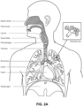
- the respiratory system of the body facilitates gas exchange.
- the nose and mouth form the entrance to the airways of a patient.
- the airways include a series of branching tubes, which become narrower, shorter and more numerous as they penetrate deeper into the lung.
- the prime function of the lung is gas exchange, allowing oxygen to move from the inhaled air into the venous blood and carbon dioxide to move in the opposite direction.
- the trachea divides into right and left main bronchi, which further divide eventually into terminal bronchioles.
- the bronchi make up the conducting airways, and do not take part in gas exchange. Further divisions of the airways lead to the respiratory bronchioles, and eventually to the alveoli.
- the alveolated region of the lung is where the gas exchange takes place, and is referred to as the respiratory zone. See “Respiratory Physiology", by John B. West, Lippincott Williams & Wilkins, 9th edition published 2012.
- a range of respiratory disorders exist. Certain disorders may be characterised by particular events, e.g. apneas, hypopneas, and hyperpneas.
- respiratory disorders include Obstructive Sleep Apnea (OSA), Cheyne-Stokes Respiration (CSR), respiratory insufficiency, Obesity Hyperventilation Syndrome (OHS), Chronic Obstructive Pulmonary Disease (COPD), Neuromuscular Disease (NMD) and Chest wall disorders.
- OSA Obstructive Sleep Apnea
- CSR Cheyne-Stokes Respiration
- OOS Obesity Hyperventilation Syndrome
- COPD Chronic Obstructive Pulmonary Disease
- NMD Neuromuscular Disease
- Chest wall disorders examples include Obstructive Sleep Apnea (OSA), Cheyne-Stokes Respiration (CSR), respiratory insufficiency, Obesity Hyperventilation Syndrome (OHS), Chronic Obstructive Pulmonary Disease (COPD), Neuromuscular Disease (NMD) and Chest wall disorders.
- Obstructive Sleep Apnea a form of Sleep Disordered Breathing (SDB), is characterised by events including occlusion or obstruction of the upper air passage during sleep. It results from a combination of an abnormally small upper airway and the normal loss of muscle tone in the region of the tongue, soft palate and posterior oropharyngeal wall during sleep.
- the condition causes the affected patient to stop breathing for periods typically of 30 to 120 seconds in duration, sometimes 200 to 300 times per night. It often causes excessive daytime somnolence, and it may cause cardiovascular disease and brain damage.
- the syndrome is a common disorder, particularly in middle aged overweight males, although a person affected may have no awareness of the problem. See US Patent No. 4,944,310 (Sullivan ).
- CSR Cheyne-Stokes Respiration
- CSR cycles rhythmic alternating periods of waxing and waning ventilation known as CSR cycles.
- CSR is characterised by repetitive de-oxygenation and re-oxygenation of the arterial blood. It is possible that CSR is harmful because of the repetitive hypoxia. In some patients CSR is associated with repetitive arousal from sleep, which causes severe sleep disruption, increased sympathetic activity, and increased afterload. See US Patent No. 6,532,959 (Berthon-Jones ).
- Respiratory failure is an umbrella term for respiratory disorders in which the lungs are unable to inspire sufficient oxygen or exhale sufficient CO 2 to meet the patient's needs. Respiratory failure may encompass some or all of the following disorders.
- a patient with respiratory insufficiency (a form of respiratory failure) may experience abnormal shortness of breath on exercise.
- Obesity Hyperventilation Syndrome is defined as the combination of severe obesity and awake chronic hypercapnia, in the absence of other known causes for hypoventilation. Symptoms include dyspnea, morning headache and excessive daytime sleepiness.
- COPD Chronic Obstructive Pulmonary Disease
- COPD encompasses any of a group of lower airway diseases that have certain characteristics in common. These include increased resistance to air movement, extended expiratory phase of respiration, and loss of the normal elasticity of the lung. Examples of COPD are emphysema and chronic bronchitis. COPD is caused by chronic tobacco smoking (primary risk factor), occupational exposures, air pollution and genetic factors. Symptoms include: dyspnea on exertion, chronic cough and sputum production.
- Neuromuscular Disease is a broad term that encompasses many diseases and ailments that impair the functioning of the muscles either directly via intrinsic muscle pathology, or indirectly via nerve pathology.
- Some NMD patients are characterised by progressive muscular impairment leading to loss of ambulation, being wheelchair-bound, swallowing difficulties, respiratory muscle weakness and, eventually, death from respiratory failure.
- Neuromuscular disorders can be divided into rapidly progressive and slowly progressive: (i) Rapidly progressive disorders: Characterised by muscle impairment that worsens over months and results in death within a few years (e.g.
- ALS Amyotrophic lateral sclerosis
- DMD Duchenne muscular dystrophy
- Variable or slowly progressive disorders Characterised by muscle impairment that worsens over years and only mildly reduces life expectancy (e.g. Limb girdle, Facioscapulohumeral and Myotonic muscular dystrophy).
- Symptoms of respiratory failure in NMD include: increasing generalised weakness, dysphagia, dyspnea on exertion and at rest, fatigue, sleepiness, morning headache, and difficulties with concentration and mood changes.
- Chest wall disorders are a group of thoracic deformities that result in inefficient coupling between the respiratory muscles and the thoracic cage.
- the disorders are usually characterised by a restrictive defect and share the potential of long term hypercapnic respiratory failure.
- Scoliosis and/or kyphoscoliosis may cause severe respiratory failure.
- Symptoms of respiratory failure include: dyspnea on exertion, peripheral oedema, orthopnea, repeated chest infections, morning headaches, fatigue, poor sleep quality and loss of appetite.
- a range of therapies have been used to treat or ameliorate such conditions. Furthermore, otherwise healthy individuals may take advantage of such therapies to prevent respiratory disorders from arising. However, these have a number of shortcomings.
- CPAP Continuous Positive Airway Pressure
- NMV Non-invasive ventilation
- IV Invasive ventilation
- Continuous Positive Airway Pressure (CPAP) therapy has been used to treat Obstructive Sleep Apnea (OSA).
- OSA Obstructive Sleep Apnea
- the mechanism of action is that continuous positive airway pressure acts as a pneumatic splint and may prevent upper airway occlusion, such as by pushing the soft palate and tongue forward and away from the posterior oropharyngeal wall.
- Treatment of OSA by CPAP therapy may be voluntary, and hence patients may elect not to comply with therapy if they find devices used to provide such therapy one or more of: uncomfortable, difficult to use, expensive and aesthetically unappealing.
- Non-invasive ventilation provides ventilatory support to a patient through the upper airways to assist the patient breathing and/or maintain adequate oxygen levels in the body by doing some or all of the work of breathing.
- the ventilatory support is provided via a non-invasive patient interface.
- NIV has been used to treat CSR and respiratory failure, in forms such as OHS, COPD, NMD and Chest Wall disorders. In some forms, the comfort and effectiveness of these therapies may be improved.
- IV Invasive ventilation
- These therapies may be provided by a treatment system or device. Such systems and devices may also be used to diagnose a condition without treating it.
- a treatment system may comprise a Respiratory Pressure Therapy Device (RPT device), an air circuit, a humidifier, a patient interface, and data management.
- RPT device Respiratory Pressure Therapy Device
- a patient interface may be used to interface respiratory equipment to its wearer, for example by providing a flow of air to an entrance to the airways.
- the flow of air may be provided via a mask to the nose and/or mouth, a tube to the mouth or a tracheostomy tube to the trachea of a patient.
- the patient interface may form a seal, e.g., with a region of the patient's face, to facilitate the delivery of gas at a pressure at sufficient variance with ambient pressure to effect therapy, e.g., at a positive pressure of about 10 cmH 2 O relative to ambient pressure.
- the patient interface may not include a seal sufficient to facilitate delivery to the airways of a supply of gas at a positive pressure of about 10 cmH 2 O.
- Certain other mask systems may be functionally unsuitable for the present field.
- purely ornamental masks may be unable to maintain a suitable pressure.
- Mask systems used for underwater swimming or diving may be configured to guard against ingress of water from an external higher pressure, but not to maintain air internally at a higher pressure than ambient.
- Certain masks may be clinically unfavourable for the present technology e.g. if they block airflow via the nose and only allow it via the mouth.
- Certain masks may be uncomfortable or impractical for the present technology if they require a patient to insert a portion of a mask structure in their mouth to create and maintain a seal via their lips.
- Certain masks may be impractical for use while sleeping, e.g. for sleeping while lying on one's side in bed with a head on a pillow.
- the design of a patient interface presents a number of challenges.
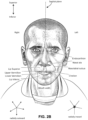
- the face has a complex three-dimensional shape.
- the size and shape of noses and heads varies considerably between individuals. Since the head includes bone, cartilage and soft tissue, different regions of the face respond differently to mechanical forces.
- the jaw or mandible may move relative to other bones of the skull. The whole head may move during the course of a period of respiratory therapy.
- masks suffer from being one or more of obtrusive, aesthetically undesirable, costly, poorly fitting, difficult to use, and uncomfortable especially when worn for long periods of time or when a patient is unfamiliar with a system. Wrongly sized masks can give rise to reduced compliance, reduced comfort and poorer patient outcomes.
- Masks designed solely for aviators, masks designed as part of personal protection equipment (e.g. filter masks), SCUBA masks, or for the administration of anaesthetics may be tolerable for their original application, but nevertheless such masks may be undesirably uncomfortable to be worn for extended periods of time, e.g., several hours. This discomfort may lead to a reduction in patient compliance with therapy. This is even more so if the mask is to be worn during sleep.
- CPAP therapy is highly effective to treat certain respiratory disorders, provided patients comply with therapy. If a mask is uncomfortable, or difficult to use a patient may not comply with therapy. Since it is often recommended that a patient regularly wash their mask, if a mask is difficult to clean (e.g., difficult to assemble or disassemble), patients may not clean their mask and this may impact on patient compliance.
- a mask for other applications may not be suitable for use in treating sleep disordered breathing
- a mask designed for use in treating sleep disordered breathing may be suitable for other applications.
- patient interfaces for delivery of CPAP during sleep form a distinct field.
- Patient interfaces may include a seal-forming structure. Since it is in direct contact with the patient's face, the shape and configuration of the seal-forming structure can have a direct impact the effectiveness and comfort of the patient interface.
- a patient interface may be partly characterised according to the design intent of where the seal-forming structure is to engage with the face in use.
- a seal-forming structure may comprise a first sub-portion to form a seal around the left naris and a second sub-portion to form a seal around the right naris.
- a seal-forming structure may comprise a single element that surrounds both nares in use. Such single element may be designed to for example overlay an upper lip region and a nasal bridge region of a face.
- a seal-forming structure may comprise an element that surrounds a mouth region in use, e.g. by forming a seal on a lower lip region of a face.
- a seal-forming structure may comprise a single element that surrounds both nares and a mouth region in use.
- These different types of patient interfaces may be known by a variety of names by their manufacturer including nasal masks, full-face masks, nasal pillows, nasal puffs and oro-nasal masks.
- Certain seal-forming structures may be designed for mass manufacture such that one design fit and be comfortable and effective for a wide range of different face shapes and sizes. To the extent to which there is a mismatch between the shape of the patient's face, and the seal-forming structure of the mass-manufactured patient interface, one or both must adapt in order for a seal to form.
- seal-forming structure extends around the periphery of the patient interface, and is intended to seal against the patient's face when force is applied to the patient interface with the seal-forming structure in confronting engagement with the patient's face.
- the seal-forming structure may include an air or fluid filled cushion, or a moulded or formed surface of a resilient seal element made of an elastomer such as a rubber.
- seal-forming structure may comprise a friction-fit element, e.g. for insertion into a naris, however some patients find these uncomfortable.
- seal-forming structure may use adhesive to achieve a seal. Some patients may find it inconvenient to constantly apply and remove an adhesive to their face.
- nasal pillow is found in the Adam Circuit manufactured by Puritan Bennett.
- Another nasal pillow, or nasal puff is the subject of US Patent 4,782,832 (Trimble et al. ), assigned to Puritan-Bennett Corporation.
- ResMed Limited has manufactured the following products that incorporate nasal pillows: SWIFT TM nasal pillows mask, SWIFT TM II nasal pillows mask, SWIFT TM LT nasal pillows mask, SWIFT TM FX nasal pillows mask and MIRAGE LIBERTY TM full-face mask.
- a seal-forming structure of a patient interface used for positive air pressure therapy is subject to the corresponding force of the air pressure to disrupt a seal.
- a variety of techniques have been used to position the seal-forming structure, and to maintain it in sealing relation with the appropriate portion of the face.
- Another technique is the use of one or more straps and/or stabilising harnesses. Many such harnesses suffer from being one or more of ill-fitting, bulky, uncomfortable and awkward to use.
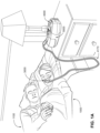
- a flow of pressurised air is provided to a patient interface through a conduit in an air circuit that fluidly connects to the patient interface so that, when the patient interface is positioned on the patient's face during use, the conduit extends out of the patient interface forwards away from the patient's face.
- This may sometimes be referred to as an "elephant trunk" style of interface.
- An alternative type of treatment system which seeks to address these problems comprises a patient interface in which a tube that delivers pressurised air to the patient's airways also functions as part of the structure to position and stabilise the seal-forming portion of the patient interface to the appropriate part of the patient's face, also referred to as "headgear".
- This type of patient interface may be referred to as incorporating 'headgear tubing' or 'conduit headgear'.
- Such patient interfaces allow the conduit in the air circuit providing the flow of pressurised air from a respiratory pressure therapy device to connect to the patient interface in a position other than in front of the patient's face.
- a treatment system is disclosed in US Patent Publication No. 2007/0246043 , in which the conduit connects to a tube in the patient interface through a port positioned in use on top of the patient's head.
- the Philips DreamWear TM mask includes such headgear tubing.
- the length of the DreamWear TM headgear tubes cannot be adjusted. Consequently, the DreamWear TM headgear is supplied in three different sizes to cater for different sized patient faces. Providing a greater number of different sizes may increase the complexity and cost to manufacture the headgear and may result in larger packaging. Additionally, a supply of discretely sized masks may limit the extent to which differently sized patient heads can be accommodated. There may be a greater chance of some patients being unable to achieve what they consider a "perfect" fit if forced to choose between discrete sizes that are not adjustable in length.
- Patient interfaces incorporating headgear tubing may provide some advantages, for example avoiding a conduit connecting to the patient interface at the front of a patient's face, which may be unsightly and obtrusive. However, it is desirable for patient interfaces incorporating headgear tubing to be comfortable for a patient to wear over a prolonged duration when the patient is asleep while forming an effective seal with the patient's face.
- a respiratory pressure therapy (RPT) device may be used to deliver one or more of a number of therapies described above, such as by generating a flow of air for delivery to an entrance to the airways.
- the flow of air may be pressurised.
- RPT devices include a CPAP device and a ventilator.
- Air pressure generators are known in a range of applications, e.g. industrial-scale ventilation systems. However, air pressure generators for medical applications have particular requirements not fulfilled by more generalised air pressure generators, such as the reliability, size and weight requirements of medical devices. In addition, even devices designed for medical treatment may suffer from shortcomings, pertaining to one or more of: comfort, noise, ease of use, efficacy, size, weight, manufacturability, cost, and reliability.
- the designer of a device may be presented with an infinite number of choices to make. Design criteria often conflict, meaning that certain design choices are far from routine or inevitable. Furthermore, the comfort and efficacy of certain aspects may be highly sensitive to small, subtle changes in one or more parameters.
- a range of artificial humidification devices and systems are known, however they may not fulfil the specialised requirements of a medical humidifier.
- Medical humidifiers are used to increase humidity and/or temperature of the flow of air in relation to ambient air when required, typically where the patient may be asleep or resting (e.g. at a hospital).
- a medical humidifier for bedside placement may be small.
- a medical humidifier may be configured to only humidify and/or heat the flow of air delivered to the patient without humidifying and/or heating the patient's surroundings.
- Room-based systems e.g. a sauna, an air conditioner, or an evaporative cooler
- medical humidifiers may have more stringent safety constraints than industrial humidifiers
- Some forms of treatment systems may include a vent to allow the washout of exhaled carbon dioxide.
- the vent may allow a flow of gas from an interior space of a patient interface, e.g., the plenum chamber, to an exterior of the patient interface, e.g., to ambient.
- the vent may comprise an orifice and gas may flow through the orifice in use of the mask. Many such vents are noisy. Others may become blocked in use and thus provide insufficient washout. Some vents may be disruptive of the sleep of a bed partner 1100 of the patient 1000, e.g. through noise or focussed airflow.
- US 2018/250482 A1 relates to a PAP device to generate a supply of pressurized air, a patient interface adapted to form a seal with the patient's face, air delivery tubing to interconnect the patient interface and the PAP device, and a cover that substantially encloses at least a portion of the PAP device and a portion of the air delivery tubing.
- the cover allows the PAP device to be carried by and/or supported on the patient's head.
- US 2019/269870 A1 relates to an air delivery system for providing a supply of air from a source of air at positive pressure to an interfacing structure located at the entrance to the airways of a patient including a manifold adapted to connect with the supply of positive air pressure and at least one tube connected to the manifold and adapted to deliver the supply of air to the interfacing structure.
- Each tube is structured to allow movement between an open phase in which the tube allows the passage of air and a collapsed phase in which the tube is collapsed.
- Each tube is structured such that weight of a typical patient's head against bedding apparel is sufficient to collapse the tube from the open phase to the collapsed phase.
- the present technology is directed towards providing medical devices used in the diagnosis, amelioration, treatment, or prevention of respiratory disorders having one or more of improved comfort, cost, efficacy, ease of use and manufacturability.
- a first aspect of the present technology relates to apparatus used in the diagnosis, amelioration, treatment or prevention of a respiratory disorder.
- Another aspect of the present technology relates to methods used in the diagnosis, amelioration, treatment or prevention of a respiratory disorder.
- a patient interface that includes a seal-forming structure constructed and arranged to form a seal with a region of the patient's face surrounding an entrance to the patient's airways for sealed delivery of a flow of pressurized air at a therapeutic pressure of at least 6 cmH2O above ambient air pressure throughout the patient's respiratory cycle in use; a plenum chamber pressurisable to the therapeutic pressure of at least 6 cmH2O above ambient air pressure; and positioning and stabilising structure to provide a force to hold a seal-forming structure in a therapeutically effective position on a patient's head.
- a patient interface that includes: a plenum chamber; a seal-forming structure; a vent structure; and a positioning and stabilising structure to provide a force to hold the seal-forming structure in a therapeutically effective position on a patient's head
- the positioning and stabilising structure including at least one gas delivery tube to receive the flow of air from a connection port and to deliver the flow of air to the entrance of the patient's airways via the seal-forming structure, the gas delivery tube being constructed and arranged to contact, in use, at least a region of the patient's head superior to an otobasion superior of the patient's head.
- a positioning and stabilising structure to provide a force to hold a seal-forming structure in a therapeutically effective position on a patient's head, the seal-forming structure constructed and arranged to form a seal with a region of the patient's face surrounding an entrance to the patient's airways for sealed delivery of a flow of air at a therapeutic pressure of at least 6 cmH 2 O above ambient air pressure throughout the patient's respiratory cycle in use,
- the positioning and stabilising structure comprising: at least one gas delivery tube to receive the flow of air from a connection port on top of the patient's head and to deliver the flow of air to the entrance of the patient's airways via the seal-forming structure, the gas delivery tube being constructed and arranged to contact, in use, at least a region of the patient's head superior to an otobasion superior of the patient's head, the gas delivery tube comprising a tube wall defining a hollow interior through which air is able to flow to the seal-forming structure, wherein at least a portion
- patient interface comprising:
- the patient contacting portion may comprise a section of transparent and/or translucent material, wherein a portion of the section of transparent and/or translucent material is configured to receive the textile material or foam material.
- the section of transparent and/or translucent material of the non-patient contacting portion may comprise an adhesive layer configured to be bonded to the textile material or foam material.
- the non-patient contacting portion may comprise a section configured to receive the section of transparent and/or translucent material.
- the textile material or foam material of the non-patient contacting portion may comprise: (a) an adhesive layer configured to be bonded to the section of transparent and/or translucent material; or (b) a layer of hook and loop material configured to co-operatively engage with a complementary layer of hook and loop material bonded to the section of transparent and/or translucent material.
- one of the patient contacting portion or non-patient contacting portion is configured to receive: (a) an adhesive layer to which the other of the patient contacting portion or non-patient contacting portion may be bonded; or (b) a layer of hook and loop material configured to co-operatively engage with a complementary layer of hook and loop material bonded to the other of the patient contacting portion or non-patient contacting portion.
- the non-patient contacting portion may comprise two more layers.
- the non-patient contacting portion may comprise an outer layer of transparent and/or translucent material and at least a first inner layer of a thermoplastic material defining at least a portion of an air path within the at least one gas delivery tube.
- the section of transparent and/or translucent material may run substantially the length of the at least one gas delivery tube. In another example of this technology, the section of transparent and/or translucent material may run a portion of the length of the at least one gas delivery tube. In yet another example of this technology, the transparent and/or translucent material may be arranged in discrete sections, each section separated by a section of non-transparent and/or translucent material, such as textile material or foam material, along the length of the at least one gas delivery tube.
- the anterior side of the non-patient contacting portion may have a different rigidity to the posterior side; (a) the anterior side of the non-patient contacting portion may comprise a greater rigidity than the posterior side of the non-patient contacting portion; (b) the anterior side of the non-patient contacting portion and/or the posterior side of the non-patient contacting portion may have a rigidity which varies along the length of the at least one gas delivery tube; (c) the rigidity of the anterior side of the non-patient contacting portion and/or the posterior side of the non-patient contacting portion may be greater at an inferior portion of the at least one gas delivery tube than at a superior portion of the at least one gas delivery tube.
- the section of transparent and/or translucent material of the second outer layer may be formed from an elastomer, wherein the elastomer is one or more of a) silicone; b) thermoplastic elastomer (TPE); or c) thermoplastic polyurethane (TPU).
- the elastomer is one or more of a) silicone; b) thermoplastic elastomer (TPE); or c) thermoplastic polyurethane (TPU).
- the patient contacting portion and/or the non-patient contacting portion may be thermoformed to shape;
- the at least one gas delivery tube may comprise a substantially D-shaped cross section;
- the at least one gas delivery tube may comprise a substantially rectangular cross section with two or more rounded corners;
- the at least one gas delivery tube may vary in width from 34mm to 18mm along a length of the at least one gas delivery tube;
- the at least one gas delivery tube may vary in height from 8mm to 6mm along a length of the at least one gas delivery tube; and/or (f) the non-patient contacting portion comprises a transparent material only.
- the D-shaped cross section includes a substantially flat surface and an arcuate surface, the flat surface forming the patient contacting portion and the arcuate surface forming the non-patient contacting portion;
- the arcuate surface includes a first section and a second section, the first section being constructed from the transparent and/or translucent material, and the second section being constructed from the textile material or foam material; and/or (iii) the first section is directly coupled to the flat surface, and the second section is disposed opposite to the flat surface.
- method of manufacturing comprises positioning the textile material or the foam material in a mold; introducing the transparent and/or translucent material into the mold; bonding the transparent and/or translucent material to the textile material and/or the foam material in order to form the at least one gas delivery tube; and connecting the at least one gas delivery tube to the plenum chamber and/or the seal forming structure.
- the mold includes a semi-circular protrusion and the transparent and/or translucent material flowing around the semi-circular protrusion and creating a semi-circular recess along the hollow interior; and/or (b) the semi-circular protrusion directs the transparent and/or translucent material toward the textile material or the foam material in order to allow bonding between the transparent and/or translucent material and the textile material or the foam material prior to forming the non-patient contacting portion.
- a positioning and stabilising structure to provide a force to hold a seal-forming structure in a therapeutically effective position on a patient's head, the seal-forming structure constructed and arranged to form a seal with a region of the patient's face surrounding an entrance to the patient's airways for sealed delivery of a flow of air at a therapeutic pressure of at least 6 cmH 2 O above ambient air pressure throughout the patient's respiratory cycle in use,
- the positioning and stabilising structure comprising: at least one gas delivery tube to receive the flow of air from a connection port on top of the patient's head and to deliver the flow of air to the entrance of the patient's airways via the seal-forming structure, the at least one gas delivery tube being constructed and arranged to contact, in use, at least a region of the patient's head superior to an otobasion superior of the patient's head, the at least one gas delivery tube comprising a tube wall defining a hollow interior through which air is able to flow to the seal-forming structure, and
- the transparent section may run substantially the length of the at least one gas delivery tube. In another example of this technology, the transparent section runs a portion of the length of the at least one gas delivery tube. In yet another example of this technology, the transparent section is arranged at regular intervals along the length of the at least one gas delivery tube.
- the rigidising element may be provided to one of the anterior edge and the posterior sides of the at least one gas delivery tube.
- the anterior side of the at least one gas delivery tube may have a different rigidity to the posterior side of the at least one gas delivery tube; (a) the anterior side of the at least one gas delivery tube may comprise a greater rigidity than the posterior side of the at least one gas delivery tube; (b) the anterior side of the at least one gas delivery tube and/or the posterior side of the at least one gas delivery tube may have a rigidity which varies along the length of the at least one gas delivery tube; (c) the rigidity of the anterior side of the at least one gas delivery tube and/or the posterior side of the at least one gas delivery tube may be greater at an inferior portion of the at least one gas delivery tube than at a superior portion of the at least one gas delivery tube.
- the first portion is the anterior side of the at least one gas delivery tube and the second portion is the posterior side of the at least one gas delivery tube or the first portion is the posterior portion of the at least one gas delivery tube and the second portion is the anterior portion of the at least one gas delivery tube.
- the non-patient contacting side includes an anterior facing side and a posterior facing side, configured to face in an anterior direction and a posterior direction respectively, in use.
- the anterior facing side and the posterior facing side are each constructed from the transparent and/or translucent material; and/or (b) the transverse axis extends generally from the anterior direction to the posterior direction includes only the transparent and/or translucent material.
- the at least one gas delivery tube is selectively coupled to the plenum chamber, and is configured to be removed in order to allow the patient to clean within the tube.
- a positioning and stabilising structure to provide a force to hold a seal-forming structure in a therapeutically effective position on a patient's head, the seal-forming structure constructed and arranged to form a seal with a region of the patient's face surrounding an entrance to the patient's airways for sealed delivery of a flow of air at a therapeutic pressure of at least 6 cmH 2 O above ambient air pressure throughout the patient's respiratory cycle in use,
- the positioning and stabilising structure comprising: at least one gas delivery tube to receive the flow of air from a connection port on top of the patient's head and to deliver the flow of air to the entrance of the patient's airways via the seal-forming structure, the at least one gas delivery tube being constructed and arranged to contact, in use, at least a region of the patient's head superior to an otobasion superior of the patient's head, the at least one gas delivery tube comprising a tube wall defining a hollow interior through which air is able to flow to the seal-forming structure, the
- the first layer of textile material is a) bonded to the second outer layer by adhesive; b) bonded to the second outer layer by hook and loop material.
- the first layer of textile material is also provided to the superior tube portion.
- the transparent material of the second outer layer may be an elastomer, wherein the elastomer is one or more of a) silicone; b) thermoplastic elastomer (TPE); or c) thermoplastic polyurethane (TPU).
- the elastomer is one or more of a) silicone; b) thermoplastic elastomer (TPE); or c) thermoplastic polyurethane (TPU).
- Another aspect of certain forms of the present technology is a system for treating a respiratory disorder comprising a patient interface according to any one or more of the other aspects of the present technology, an air circuit and a source of air at positive pressure.
- a method of manufacturing a positioning and stabilising structure to provide a force to hold a seal-forming structure in a therapeutically effective position on a patient's head the seal-forming structure constructed and arranged to form a seal with a region of the patient's face surrounding an entrance to the patient's airways for sealed delivery of a flow of air at a therapeutic pressure of at least 6 cmH 2 O above ambient air pressure throughout the patient's respiratory cycle in use
- the positioning and stabilising structure comprising: at least one gas delivery tube to receive the flow of air from a connection port on top of the patient's head and to deliver the flow of air to the entrance of the patient's airways via the seal-forming structure, the gas delivery tube being constructed and arranged to contact, in use, at least a region of the patient's head superior to an otobasion superior of the patient's head, the gas delivery tube comprising a tube wall defining a hollow interior through which air is able to flow to the seal-forming structure, wherein
- An aspect of one form of the present technology is a method of manufacturing apparatus.
- An aspect of certain forms of the present technology is a medical device that is easy to use, e.g. by a person who does not have medical training, by a person who has limited dexterity, vision or by a person with limited experience in using this type of medical device.
- An aspect of one form of the present technology is a portable RPT device that may be carried by a person, e.g., around the home of the person.
- An aspect of one form of the present technology is a patient interface that may be washed in a home of a patient, e.g., in soapy water, without requiring specialised cleaning equipment.
- a patient interface comprising:
- At least one gas delivery tube coupled to the plenum chamber and configured to receive the flow of pressurized air from a connection port on top of the patient's head and to deliver the flow of pressurized air to the entrance of the patient's airways via the plenum chamber, the at least one gas delivery tube being constructed and arranged to contact, in use, at least a region of the patient's head superior to an otobasion superior of the patient's head, the at least one gas delivery tube comprising a tube wall having an interior passage for flow of pressurized air along a longitudinal axis of the tube to the seal-forming structure, wherein at least a portion of the tube wall comprises:
- the present technology comprises a method for treating a respiratory disorder comprising the step of applying positive pressure to the entrance of the airways of a patient 1000.
- a supply of air at positive pressure is provided to the nasal passages of the patient via one or both nares.
- mouth breathing is limited, restricted or prevented.
- the present technology comprises an apparatus or device for treating a respiratory disorder.
- the apparatus or device may comprise an RPT device 4000 for supplying pressurised air to the patient 1000 via an air circuit 4170 to a patient interface 3000.
- a non-invasive patient interface 3000 in accordance with one aspect of the present technology comprises the following functional aspects: a seal-forming structure 3100, a plenum chamber 3200, a positioning and stabilising structure 3300, a vent 3400, one form of connection port 3600 for connection to air circuit (e.g. the air circuit 4170 shown in Figs. 1A-1C ).
- the seal-forming structure 3100 and the plenum chamber 3200 are provided by a cushion module 3150.
- the cushion module 3150 in this example is a cradle cushion module. In other examples it may be a nasal pillows cushion module or another type of cushion module.
- a patient interface is unable to comfortably deliver a minimum level of positive pressure to the airways, the patient interface may be unsuitable for respiratory pressure therapy.
- the patient interface 3000 in accordance with one form of the present technology is constructed and arranged to be able to provide a supply of air at a positive pressure of at least 6 cmH 2 O with respect to ambient.
- the patient interface 3000 in accordance with one form of the present technology is constructed and arranged to be able to provide a supply of air at a positive pressure of at least 10 cmH 2 O with respect to ambient.
- the patient interface 3000 in accordance with one form of the present technology is constructed and arranged to be able to provide a supply of air at a positive pressure of at least 20 cmH 2 O with respect to ambient.
- a seal-forming structure 3100 provides a target seal-forming region, and may additionally provide a cushioning function.
- the target seal-forming region is a region on the seal-forming structure 3100 where sealing may occur.
- the region where sealing actually occurs- the actual sealing surface- may change within a given treatment session, from day to day, and from patient to patient, depending on a range of factors including for example, where the patient interface was placed on the face, tension in the positioning and stabilising structure and the shape of a patient's face.
- the target seal-forming region is located on an outside surface of the seal-forming structure 3100.
- the seal-forming structure 3100 is constructed from a biocompatible material, e.g. silicone rubber.
- a seal-forming structure 3100 in accordance with the present technology may be constructed from a soft, flexible, resilient material such as silicone.
- a system comprising more than one seal-forming structure 3100, each being configured to correspond to a different size and/or shape range.
- the system may comprise one form of a seal-forming structure 3100 suitable for a large sized head, but not a small sized head and another suitable for a small sized head, but not a large sized head.
- the seal-forming structure includes a pressure activated assisted sealing flange utilizing a pressure assisted sealing mechanism.
- the pressure assisted sealing flange can readily respond to a system positive pressure in the interior of the plenum chamber 3200 acting on its underside to urge it into tight sealing engagement with the face.
- the pressure assisted mechanism may act in conjunction with elastic tension in the positioning and stabilising structure.
- the seal-forming structure 3100 comprises a sealing flange and a support flange.
- the sealing flange comprises a relatively thin member with a thickness of less than about 1mm, for example about 0.25mm to about 0.45mm, which extends around the perimeter of the plenum chamber 3200.
- Support flange may be relatively thicker than the sealing flange.
- the support flange is disposed between the sealing flange and the marginal edge of the plenum chamber 3200, and extends at least part of the way around the perimeter.
- the support flange is or includes a springlike element and functions to support the sealing flange from buckling in use.
- the seal-forming structure may comprise a compression sealing portion or a gasket sealing portion.
- the compression sealing portion, or the gasket sealing portion is constructed and arranged to be in compression, e.g. as a result of elastic tension in the positioning and stabilising structure.
- the seal-forming structure comprises a region having a tacky or adhesive surface.
- a seal-forming structure may comprise one or more of a pressure-assisted sealing flange, a compression sealing portion, a gasket sealing portion, a tension portion, and a portion having a tacky or adhesive surface.
- the non-invasive patient interface 3000 comprises a seal-forming structure that forms a seal in use on a nose bridge region or on a nose-ridge region of the patient's face and the upper lip region of the patient's face.
- the seal-forming structure may be referred to as a nasal mask. This is the case, for example, with the patient interface 3000 shown in Fig. 1B .
- This seal-forming portion delivers a supply of air or breathable gas to both nares of patient 1000 through a single orifice.
- This type of seal-forming structure may be referred to as a "nasal cushion" or "nasal mask”.
- the positioning and stabilising structure 3300 shown in Figs. 3 or 4 may be utilised to hold a nasal cushion in sealing position on a patient's face.
- the seal-forming structure 3100 is configured to form a seal in use with the underside of the nose around the nares and optionally with the lip superior of the patient 1000.
- This type of seal-forming structure may be referred to as a "cradle cushion" or "sub-nasal mask”.
- the shape of the seal-forming structure may be configured to match or closely follow the underside of the patient's nose, i.e. the profile and angle of the seal-forming structure may be substantially parallel to the patient's naso-labial angle.
- the seal-forming structure comprises a bridge portion defining two orifices, each of which, in use, supplies air or breathable gas to a different one of the patient's nares.
- the bridge portion may be configured to contact or seal against the patient's columella in use.
- the seal-forming structure 3100 is configured to form a seal on an underside of the patient's nose without contacting a nasal bridge region of the patient's nose.
- patient interface may comprise a seal-forming structure 3100 in the form of a cradle cushion as described in PCT Application No. PCT/AU2018/050289, filed March 29, 2018 .
- the patient interface 3000 comprises a seal-forming portion that forms a seal in use on a chin-region, a nasal bridge region and a cheek region of the patient's face. This is the case, for example, with the patient interface 3000 shown in Fig. 1C .
- This seal-forming portion delivers a supply of air or breathable gas to both nares and mouth of patient 1000 through a single orifice.
- This type of seal-forming structure may be referred to as a "full-face mask".
- the positioning and stabilising structure 3300 shown in Figs. 3 or 4 may be utilised to hold a full-face cushion in sealing position on a patient's face.
- a patient interface 3000 that comprises a nasal seal-forming structure in the manner of a nasal cushion or nasal cradle cushion and an oral seal-forming structure that is configured to form a seal in use around the mouth of a patient (which may be referred to as a "mouth cushion” or “oral mask”).
- a mask air or breathable gas is supplied in use through orifices to the patient's nares and the patient's mouth.
- This type of seal-forming structure 3100 may be referred to as an "oronasal cushion", where there are separate sealing portions around the mouth and nose, or “ultra-compact full face cushion", where the sealing of the nose is around or close to the patient's nares.
- the nasal seal-forming structure and oral seal-forming structure are integrally formed as a single component.
- patient interface may comprise a seal-forming structure 3100 in the form of a cradle cushion as described in US Patent Application No. 62/649,376 .
- the plenum chamber 3200 has a perimeter that is shaped to be complementary to the surface contour of the face of an average person in the region where a seal will form in use. In use, a marginal edge of the plenum chamber 3200 is positioned in close proximity to an adjacent surface of the face. Actual contact with the face is provided by the seal-forming structure 3100.
- the seal-forming structure 3100 may extend in use about the entire perimeter of the plenum chamber 3200.
- the plenum chamber 3200 and the seal-forming structure 3200 are formed from a single homogeneous piece of material.
- the plenum chamber 3200 does not cover the eyes of the patient in use. In other words, the eyes are outside the pressurised volume defined by the plenum chamber.
- Such forms tend to be less obtrusive and / or more comfortable for the wearer, which can improve compliance with therapy.
- the plenum chamber 3200 is constructed from a transparent material, e.g. a transparent polycarbonate.
- a transparent material can reduce the obtrusiveness of the patient interface, and help improve compliance with therapy.
- the use of a transparent material can aid a clinician to observe how the patient interface is located and functioning.
- the plenum chamber 3200 is constructed from a translucent material.
- a translucent material can reduce the obtrusiveness of the patient interface, and help improve compliance with therapy.
- the seal-forming structure 3100 of the patient interface 3000 of the present technology may be held in sealing position in use by the positioning and stabilising structure 3300.
- Positioning and stabilising structure 3300 may be referred to as "headgear" since it engages the patient's head in order to hold the patient interface 3000 in a sealing position.
- the positioning and stabilising structure 3300 provides a retention force at least sufficient to overcome the effect of the positive pressure in the plenum chamber 3200 to lift off the face.
- the positioning and stabilising structure 3300 provides a retention force to overcome the effect of the gravitational force on the patient interface 3000.
- the positioning and stabilising structure 3300 provides a retention force as a safety margin to overcome the potential effect of disrupting forces on the patient interface 3000, such as from tube drag, or accidental interference with the patient interface.
- a positioning and stabilising structure 3300 is provided that is configured in a manner consistent with being worn by a patient while sleeping.
- the positioning and stabilising structure 3300 has a low profile, or cross-sectional thickness, to reduce the perceived or actual bulk of the apparatus.
- the positioning and stabilising structure 3300 comprises at least one strap having a rectangular cross-section.
- the positioning and stabilising structure 3300 comprises at least one flat strap.
- a positioning and stabilising structure 3300 is provided that is configured so as not to be too large and bulky to prevent the patient from lying in a supine sleeping position with a back region of the patient's head on a pillow.
- a positioning and stabilising structure 3300 is provided that is configured so as not to be too large and bulky to prevent the patient from lying in a side sleeping position with a side region of the patient's head on a pillow.
- a positioning and stabilising structure 3300 is provided with a decoupling portion located between an anterior portion of the positioning and stabilising structure 3300, and a posterior portion of the positioning and stabilising structure 3300.
- the decoupling portion does not resist compression and may be, e.g. a flexible or floppy strap.
- the decoupling portion is constructed and arranged so that when the patient lies with their head on a pillow, the presence of the decoupling portion prevents a force on the posterior portion from being transmitted along the positioning and stabilising structure 3300 and disrupting the seal.
- a positioning and stabilising structure 3300 comprises a strap constructed from a laminate of a fabric patient-contacting layer, a foam inner layer and a fabric outer layer.
- the foam is porous to allow moisture, (e.g., sweat), to pass through the strap.
- the fabric outer layer comprises loop material to engage with a hook material portion.
- a positioning and stabilising structure 3300 comprises a strap that is extensible, e.g. resiliently extensible.
- the strap may be configured in use to be in tension, and to direct a force to draw a seal-forming structure into sealing contact with a portion of a patient's face.
- the strap may be configured as a tie.
- a tie will be understood to be a structure designed to resist tension.
- a tie may be part of the positioning and stabilising structure 3300 that is under tension. Some ties will impart an elastic force as a result of this tension, as will be described.
- a tie may act to maintain the seal-forming structure 3100 in a therapeutically effective position on the patient's head.
- the positioning and stabilising structure comprises a first tie, the first tie being constructed and arranged so that in use at least a portion of an inferior edge thereof passes superior to an otobasion superior of the patient's head and overlays a portion of the parietal bone without overlaying the occipital bone.
- the first tie may be provided, for example, as part of a patient interface that comprises a cradle cushion, nasal pillows, nasal cushion, full-face cushion or an oronasal cushion.
- the positioning and stabilising structure 3300 of Fig. 3 comprises a first tie in the form of gas delivery tubes 3350 which lie over the top of the patient's head.
- the gas delivery tubes 3350 may also be known as headgear tubes 3350 as they provide functions of headgear.
- the positioning and stabilising structure includes a second tie, the second tie being constructed and arranged so that in use at least a portion of a superior edge thereof passes inferior to an otobasion inferior of the patient's head and overlays or lies inferior to the occipital bone of the patient's head.
- the second tie may be provided, for example, as part of a patient interface that comprises a cradle cushion, nasal pillows, full-face cushion, nasal cushion or an oronasal cushion.
- the positioning and stabilising structure 3300 of Fig. 3 comprises a second tie in the form of a strap 3310 that lies against posterior surfaces of the patient's head.
- a positioning and stabilising structure 3300 comprises a strap that is bendable and e.g. non-rigid.
- An advantage of this aspect is that the strap is more comfortable for a patient to lie upon while the patient is sleeping.
- the positioning and stabilising structure 3300 of Fig. 3 comprises a strap 3310 that is bendable.
- the strap 3310 may be considered a backstrap.
- the strap 3310 is sufficiently flexible to pass around the back of the patient's head and lie comfortably against the patient's head, even when under tension in use.
- a system comprising more than one positioning and stabilizing structure 3300, each being configured to provide a retaining force to correspond to a different size and/or shape range.
- the system may comprise one form of positioning and stabilizing structure 3300 suitable for a large sized head, but not a small sized head, and another suitable for a small sized head, but not a large sized head.
- the positioning and stabilising structure 3300 comprises only a single tube 3350 configured to overlie the patient's head on one side.
- a strap or other stabilising component may be provided to the other side of the patient's head between the top end of the single tube 3350 and the seal-forming structure 3100, to provide balanced forces on the seal-forming structure 3100.
- the positioning and stabilising structure 3300 may be described as being inflatable. It will be understood that an inflatable positioning and stabilising structure 3300 does not require all components of the positioning and stabilising structure 3300 to be inflatable.
- the positioning and stabilising structure 3300 comprises the headgear tubing 3350, which is inflatable, and the strap 3310, which is not inflatable.
- the patient interface 3000 may comprise a connection port 3600 located proximal a top, side or rear portion of a patient's head.
- the connection port 3600 is located on top of the patient's head.
- the patient interface 3000 comprises an elbow 3610 to which the connection port 3600 is provided.
- the elbow 3610 may swivel with respect to the positioning and stabilising structure 3300 and order to decouple movement of a conduit connected to the connection port 3600 from the positioning and stabilising structure 3300.
- the connection port may be configured as a fluid connection opening 3390, as shown in Fig.
- a conduit connected to the connection port 3600 may swivel with respect to the elbow 3610.
- elbow 3610 comprises a swivelling conduit connector comprising the connection port 3600 to which a conduit of the air circuit 4170 is able to connect, such that the conduit can rotate about its longitudinal axis with respect to the elbow 3610.
- the air circuit 4170 may connect to the fluid connection opening.
- the elbow 3610 may rotatably connect to the fluid connection opening or to a ring received in the fluid connection opening.
- Patient interfaces in which the connection port 3600 is not positioned in front of the patient's face may be advantageous as some patients find a conduit that connects to a patient interface 3000 in front of the face to be unsightly and/or obtrusive.
- a conduit connecting to a patient interface 3000 in front of the face may be prone to being tangled up in bedclothes or bed linen, particularly if the conduit extends downwardly from the patient interface in use.
- Forms of the technology with a patient interface with a connection port positioned proximate the top of the patient's head in use may make it easier or more comfortable for a patient to lie or sleep in one or more of the following positions: in a side or lateral position; in a supine position (i.e. on their back, facing generally upwards); and in a prone position (i.e. on their front, facing generally downwards).
- connecting a conduit to the front of a patient interface may exacerbate a problem known as tube drag, wherein the conduit may provide an undesired drag force upon the patient interface thereby causing dislodgement away from the face.
- the positioning and stabilising structure may alternatively be provided as a single gas delivery tube having left and right arms, as shown in Fig. 4 .
- the connection port 3600 is provided to the superior side of the positioning and stabilising structure rather than being a separate connection module as in the example of Fig. 3 .
- the tubes 3350 in the form of the technology shown in Figs. 3 and 4 have a length of between 15 and 30 cm each, for example between 20 and 27 cm each.
- the length of the tubes is selected to be appropriate for the dimensions of the heads of typical patients, for example the distance between the region proximate the top of the head where the upper end of the tubes 3350 are situated, and the region proximate the openings to the patient's airways at which the lower end of the tubes 3350 connect to the plenum chamber 3200 when following a generally arcuate path down the sides of the heads and across the patient's cheek region (such as the arcuate path taken by the tubes 3350 shown in Figs. 3 and 4 ).
- the patient interface 3000 may be configured so that the length of the tubes 3350 can be varied. It will be appreciated that the length of the tubes 3350 will depend on the length of other components in the patient interface 3000, for example the length of the crown connector 3360 to which the superior ends of the tubes 3350 connect and/or the size of the plenum chamber 3200.
- the cross-sectional shape of the gas delivery tubes 3350 may be circular, elliptical, oval, D-shaped, trapezoidal or a rounded rectangle, for example as described in US Patent No. 6,044,844 .
- the cross-sectional width and/or height of the tubes 3350 may be in the range 8-35mm.
- the tubes may have a width in the range 15-25mm, and a height in the range 6-15mm.
- the height may be considered to be the dimension of the tube extending away from the patient's face in use, i.e. the distance between a patient contacting portion 3348 and the outermost part of a non-patient contacting portion 3349, while the width may be considered to be the dimension across the surface of the patient's head.
- the cross-sectional thickness of the material forming the tubes 3350 may be in the range 0.8-1.6mm, for example 1.0-1.5mm.
- Fig. 5 shows a cross-section through a gas delivery tube 3350 having a substantially D-shaped profile.
- the flat side of the profile contacts the patient's face and head and should be understood to be the patient contacting portion of the gas delivery tube.
- the raised or arcuate side of the profile should be understood to be the non-patient contacting portion of the gas delivery tube.
- the gas delivery tube may have a more square or rectangular shaped profile, configured with slightly rounded corners for patient comfort.
- the textile material of the non-patient contacting side 3354 may be stiffened (e.g., by the gas impermeable layer, by an added stiffener, etc.) in order to assist in maintaining the acuate shape.
- no stiffeners may be included, and the arcuate D-shape may only be formed when pressurized air flows through the gas delivery tube 3350.
- the textile material that comprises the gas delivery tube may be a blend of polyamide, for example, a nylon, polyester and/or spandex, and weighted from between 50g/m 2 to 250g/m 2 .
- the textile material may be of a material weighted to 120g/m 2 .
- the inner layer of the textile material may comprise two or more laminate coats of silicone.
- each laminate coat of silicone may be between 5 to 75 microns thick.
- each laminate coat of silicone may be between 20 to 30 microns thick, preferably 25 microns thick.
- the anterior and posterior sides 3355, 3356 of the D-shaped profile where the patient contacting side of the gas delivery tube 3350 and the non-patient contacting side of the gas delivery tube 3350 meet, are formed from a transparent material.
- This transparent material forms window sections in the profile of the gas delivery tube 3350 which enables the user to visibly inspect its interior. This allows for easier detection of build-up of mould and/or dirt and facilitates better cleaning of the interior while still retaining the comfort of a substantially textile exterior.
- both the patient contacting side 3351 and non-patient contacting side 3354 of the gas delivery tube 3350 are each formed from a single strip of textile material.
- the gas delivery tube of Figs. 5 and 6 is configured with two window sections, one window section along each of the anterior 3355 and posterior sides 3356 of the gas delivery tube.
- a transverse axis TA may extend through both the anterior side 3355 and the posterior side 3356 in a direction transverse to a longitudinal axis LA, which extends generally along at least a portion of the gas delivery tube 3350 (e.g., along the interface between the plenum chamber 3200 and the positioning and stabilizing structure 3300) in a direction of the flow of pressurized air.
- the transverse axis may not pass through either strip of textile material.
- the transverse axis may extend along the strip of textile material that forms the patient contacting side 3351 in the anterior/posterior direction, but does not intersect the strip of textile material that forms the non-patient contacting side 3354.
- a patient looking along the transverse axis TA may be able to see entirely through the gas delivery tube 3350.
- the gas delivery tube 3350 includes no opaque material when viewed along the transverse axis TA. The patient may be able to more clearly identify and debris within the gas delivery tube 3350, because said debris may block a clear line of sight along the transverse axis TA.
- a transverse plane i.e., a plane including the transverse axis TA
- the longitudinal axis LA i.e., cross-section viewed in Fig. 5
- a transverse plane i.e., a plane including the transverse axis TA
- the longitudinal axis LA i.e., cross-section viewed in Fig. 5
- Each strip of textile material has opposing edges along its elongate dimension; the transparent material of the window sections are bonded to the respective edges of the patient contacting side 3351 and non-patient 3354 contacting side, using adhesives or heat welding techniques.
- the window sections may be overmoulded to the edges of the textile material of the patient contacting side 3351 and non-patient 3354 contacting side.
- the non-patient contacting side 3354 may be formed from two or more strips of textile material interspersed with a transparent material.
- the non-patient contacting side 3354 may be formed from two strips of textile material, separated by a single strip of transparent material, bonded or overmoulded to the respective edges of the textile material.
- this places a window section in the centre of the arcuate side of the D-shaped profile.
- the patient contacting and non-patient contacting side of the gas delivery tube is formed from a single strip of textile material, the edges of the textile material being positioned substantially centrally on the non-patient contacting side 3354 of the D-shaped profile or alternatively to one side.
- the window section in this example is positioned between the elongate edges of the textile material.
- the transparent material is positioned (e.g., overmolded) between the elongated edges of the textile material, so that the edges do not completely connect.
- a patient would have only a single viewing window, and would be unable to see completely through the gas delivery tube 3350.
- the transparent material forming the window sections 3355, 3356 is an elastomeric material.
- the transparent material is a silicone of a medical grade.
- the silicone may be selected from silicones having a Shore A durometer measurement ranging between 35 and 45; i.e. from soft to medium soft.
- the silicone has a Shore A durometer measurement of between 38 and 42.
- the silicone has a Shore A durometer measurement of 40.
- a harder durometer measurement may be used to provide the gas delivery tube with greater structural integrity.
- this may also mean that there is greater potential for added pressure should the non-patient contacting side inadvertently come into contact with the face of the patient while wearing the positioning and stabilising structure. This may cause discomfort for the patient.
- the transparent material may be TPE or TPU of an appropriate softness.
- TPE is its relative low cost and the lower temperatures required for working.
- TPE can be moulded at temperatures less than 50° C with a shorter cycle time compared to an elastomer material such as silicone.
- the window sections 3355, 3356 are formed by overmoulding the silicone to strips of textile material, forming the patient contacting side 3351 and non-patient contacting side 3354 respectively.
- the textile material may be laminated or coated to form the gas impermeable layer prior to being cut into strips but in other examples, the strips may be laminated after having been fabricated, for example by flat knitting.
- the strips of textile material are inserted into a mould and the window sections 3355, 3356 moulded onto the textile material.
- This may form a one-piece construction between the textile material and the transparent material.
- the window sections 3355, 3356 include semi-circular profiles 3357 on the hollow interior of the gas delivery tube, which may have a complementary shape to the profiles 3357. These may assist in directing the flow of silicone as it is moulded such that it encourages bonding to the textile strips before the portion that forms the window section is filled. This urges the textile strips on either side of the window section towards each other for a more robust bond. Conversely, forming the window section first may bias the textile strips apart, affecting the quality and appearance of the gas delivery tube.
- a part of the length of the gas delivery tube may be configured with one or more window sections while in other examples, the entire length of the gas delivery tube 3350 may be configured with one or more window sections 3355, 3356.
- the length of the gas delivery tube may be configured with a series of window sections arranged at certain intervals and/or at strategic positions. For example, in certain forms the inferior portion of the gas delivery tube 3350, close to the plenum chamber 3200, is provided with one or more window sections while the superior portion of the gas delivery tube, close to the connection port to the air supply is not.
- at least some of the individual window sections may be separated from adjacent window sections by sections of textile material or foam material.
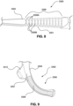
- Fig. 7 shows a gas delivery tube 3350 having a substantially D-shaped profile.
- the curved portion of the profile is the non-patient contacting side 3354 of the gas delivery tube 3350 and may be formed entirely from a transparent material, while the flat portion of the profile is the patient contacting side 3351 of the gas delivery tube and is comprised entirely of a textile material or foam material.
- the patient contacting 3351 and non-patient contacting portions 3354 are bonded at their respective flanges which, in use, form the anterior and posterior sides respectively of the gas delivery tube 3350.
- the gas delivery tube may have a substantially square or rectangular profile, which may include rounded corners for patient comfort.
- the rounded corners as opposed to sharp corners, may assist in reducing potential fault locations (e.g., where gas delivery tube 3350 might fault as a result of repeated pressurization and depressurization).
- Fig. 7 and described examples may be advantageous since it will provide a conduit headgear that is comfortable to wear but will also allow the interior of the at least a portion of the gas delivery tube, if not its entire length, to be visible to the patient.
- the inspection and cleaning of the gas delivery tube may be easier to perform.
- only a portion of the length of the non-patient contacting side may be formed from the transparent material.
- only the non-patient contacting side of the inferior end of the gas delivery tube may be comprised of the transparent material.
- the non-patient contacting side of the superior end of the gas delivery tube may be comprised of the transparent material.
- the transparent material forming the non-patient contacting side 3354 is an elastomeric material.
- the transparent material is a silicone of a medical grade.
- the silicone may be selected from silicones having a Shore A durometer measurement ranging between 35 and 45; i.e. from soft to medium soft.
- the silicone has a Shore A durometer measurement of between 38 and 42.
- the silicone has a Shore A durometer measurement of 40.
- the transparent material may be TPE or TPU of an appropriate softness.
- the patient contacting side 3351 of the gas delivery tube 3350 is constructed from an opaque textile material as previously described.
- the textile layer includes an inner layer in the form of a gas impermeable layer 3352 of a laminate of silicone or the like.
- additional layers of adhesive or further laminate layers may be provided.
- the flow path is formed between the inner gas impermeable layer 3352 and the non-patient contacting side 3354 which, as already described for this example is entirely comprised of an elastomer material and as such is medically compatible with a clean gas flow.
- the patient-contacting side 3351 may be formed from, or may comprise, a foam material.
- the tube 3350 may comprise a combination of textile and foam materials.
- the textile and/or foam materials comprising the patient-contacting side 3351 of the gas delivery tubes may: hold air under pressure, be biocompatible and suitable/approved for use in forming a medical air path, be lighter than silicone tubes, be soft and flexible, generally retain a predetermined shape, be cleanable and be durable for a predetermined lifecycle such as one month, three months, six months, a year or longer.
- the non-patient contacting side 3354 of the gas delivery tube 3350 may comprise, at least partially, one or more concertina sections 3358, as shown in Fig. 8 .
- Each concertina section 3358 may comprise a portion of the gas delivery tube 3350 having one or more folding portions, pleats, corrugations or bellows as described in PCT Application No. PCT/AU2019/050874 .
- the concertina section 3358 of the gas delivery tube 3350 is comprised at least partially of a textile material or a foam material and at least partially of a transparent material, such as silicone, TPE or TPU as previously described in previous examples.
- the textile material or foam material may be provided solely to the patient contacting side of the gas delivery tube, leaving the non-patient contacting side comprised partially or entirely of transparent material.
- the textile material and the transparent material may have similar stretch characteristics so that the patient and non-patient sides are able to stretch together (e.g., the concertina does not curve while stretching).
- the concertina does not curve while stretching.
- the concertina sections 3358 may be comprised of a series of external ridges 3359A and grooves 3359B alternatingly formed along at least a portion of the non-patient contacting side 3351 of the gas delivery tube 3350.
- corresponding ridges and grooves may be provided to the interior of the gas delivery tube but this may compromise the cost efficiency of manufacture.
- the alternating ridges 3359A and grooves 3359B of the concertina section may be formed as corrugations such that the gas delivery tube is able to deform and bend.
- the concertina section may only have limited or no functionality to be shortened or lengthened.
- the ridges 3359A and grooves 3359B may facilitate a change in shape of the concertina section 3358 of the gas delivery tube 3350 which assists in helping the gas delivery tube conform to the patient's head.
- the gas delivery tubes 3350, or portions of the gas delivery tubes, of the positioning and stabilising structure 3300 may be configured to be more resistant to bending in or about some directions or axes than in or about others.
- a tube 3350 that comprises relatively rigid portions on both the anterior and posterior sides of the tube 3350 may advantageously have a higher resistance to bending towards both the anterior and posterior sides of the tube 3350 when in use.
- a rigid portion is provided to only one of the anterior or posterior sides of the tube 3350 since, depending on the rigidity, a rigid portion on one side only may provide a sufficient resistance to bending towards both directions.
- a rigid portion may be provided along the entire length of the gas delivery tube 3350 while in further examples, a rigid portion is provided to only a portion of the length of the gas delivery tube3350.
- the rigid portion may be provided to one of the inferior portions or superior portions of the tube.
- a superior portion of each tube 3350 of the positioning and stabilising structures 3300 shown in Figs. 3 and 4 may be more bendable in a particular direction in comparison to an orthogonal direction.
- having the superior portion of the gas delivery tube more bendable may assist in the positioning and stabilising structure conforming to the shape of the patient's skull, particularly around the curvature of the crown.
- the stiffened portion(s) of the gas delivery tube may be provided by the window sections. Being formed from an elastomeric material, the window sections may inherently have greater rigidity than the textile material or foam material forming at least a substantial portion of the remainder of the gas delivery tube.
- the relative rigidity of the gas delivery tube may be determined by the configuration of the window sections.
- the rigidity of the gas delivery tube 3350 may be enhanced through increasing the thickness of one or both of the window sections 3355, 3356.
- the rigidity of the gas delivery tube may be enhanced through decreasing the thickness of one of the window sections 3355 relative to the other window section 3356.
- the thickness of the window section(s) may increase or decrease along the length of the gas delivery tube 3350. This may give differing rigidities to the inferior 3306 and superior portions 3304 of the gas delivery tube.
- a similar increase in rigidity of the gas delivery tube may be achieved by increasing the relative width of one or both of the window sections 3355, 3356, i.e. reducing the amount of textile material present and increasing the amount of the silicone present in the window section, i.e. increasing the ratio of surface area of the window section relative to the textile material of the non-patient contacting side of the gas delivery tube.
- the ratio of window section relative to textile material may range from 1:10 to 1:1.
- the window sections 3355, 3356 are about an eighth of the width of the textile strip forming the non-patient contacting side 3354, i.e. a ratio of 1:8.
- Doubling the width of the window sections 3355, 3356 with a corresponding decrease in width of the textile material forming the non-patient contacting side 3354 may increase the rigidity of the gas delivery tube.
- the width of the window sections may increase or decrease along the length of the gas delivery tube 3350, providing differing rigidities to the inferior 3306 and superior portions 3304 of the gas delivery tube.
- the rigidity may also increase the rigidity of the gas delivery tube 3350 by adding (e.g., sewing) rigidized threads to the textile material.
- the rigidized threads may provide a stiffness to the textile material, without substantially increasing the weight of the textile material.
- the rigidized threads could be used instead of a window section with an increased width, in order to reduce weight, and improve patient compliance.
- one or the other of the window sections may be configured to be more rigid than the other.
- the window section of the anterior side of the gas delivery tube may be configured such that it is more rigid that the window section of the posterior side of the gas delivery tube. This may mean that the gas delivery tube 3350 is more resistant to forces applied from a posterior direction (such as may occur when the air circuit drags or catches on bedding or the like).
- the window section of the posterior side of the gas delivery tube may be configured such that it is more rigid that the window section of the anterior side of the gas delivery tube. This may mean that the gas delivery tube 3350 is more resistant to forces applied from an anterior direction.
- Fig. 9 shows the inferior portion 3306 of a gas delivery tube 3350 when it has be decoupled from the plenum chamber 3200.
- both the patient contacting side 3351 and non-patient contacting side 3354 of the gas delivery tube 3360 is constructed primarily from a transparent material in the form of an elastomer. This means that the flow path within the gas delivery tube 3350 (or a substantial part thereof) is defined entirely by the elastomer.
- the elastomer is a silicone, which is gas impermeable and medically suitable for use for defining a hygienic flow path.
- Other examples of elastomers may be TPE or TPU.
- the patient contacting side 3351 is configured to permanently or temporarily receive a textile pad 3308 which provides a comfortable, softer surface that, in use, contacts the patient's face.
- the textile pad 3308 does not form a portion of the passage through which pressurized air flows.
- the textile pad 3308 may be added during manufacture or alternatively provided separately to the gas delivery tubes for the patient to secure to the gas delivery tube if desired. This may allow for the provision of conduit headgear in a non-textile form, leaving the patient to place the textile pads on certain areas of the patient contacting side of the gas delivery tube, according to their preference.
- textile pads may be applied to the superior portion of the gas delivery tube 3350, which contacts the crown of the head of the patient.
- the textile pad 3308 does not need to be configured with a surface that forms part of the flow path of the gas delivery tube 3350, this function being fulfilled entirely by the transparent material forming at least a substantial part of the flow path within the gas delivery tube, there may be no need for a textile that incorporates a gas impermeable layer.
- the textile pad 3308 may be comprised of one or more fabrics, for example, nylon, polyester, or spandex or blends of these.
- the textile pad 3308 may be comprised of a sufficiently stretchable and elastic material such that it does not inhibit the bendability of the conduit headgear 3300, for example, to allow for ready movement of the concertina sections 3358 of the conduit headgear of Figs. 10 to 12 .
- the textile pad 3308 is bonded to the transparent material through the use of an adhesive or similar bonding agent.
- the textile pad 3308 may be secured, for example, by hook and loop material such as VELCRO TM , to the transparent material.
- the transparent material may be overmoulded to the textile pad 3308.
- the patient contacting side 3351 of the gas delivery tube 3350 may be moulded or otherwise formed to comprise a partial recess or depression. This may be advantageous in providing a highly integrated look and feel to the gas delivery tube 3350, which may make it more appealing to the consumer.
- the recess may be provided with one of a hook and loop material, with a reverse side of the textile pad 3308 provided with the other of the hook and loop material. This allows the textile pads to be removed for washing to remove skin oils and dirt arising from contact with the patient's face.
- the textile pad 3308 extends from the inferior end of the gas delivery tube 3350 as far in the superior direction as the tab 3312 extending posteriorly from the gas delivery tube.
- the textile pad 3308 may be configured with a corresponding tab such that this covers the tab 3312 of the gas delivery tube 3350. This may improve comfort in the event that the tab 3312 of the gas delivery tube comes into contact with the face and/or hair of the patient while the positioning and stabilising structure is worn.
- Fig. 9 shows only the inferior portion 3306 of the gas delivery tube being provided with a textile pad 3308, but in other examples, the superior portion 3304 of the gas delivery tube 3350 may also or alternatively be configured with a textile pad 3308. This may be a separate textile pad to that provided to the inferior portion 3306 of the gas delivery tube or, as shown in Fig. 10 , a single textile pad may cover both the superior 3304 and inferior 3306 portions of the gas delivery tube 3350.
- a textile material covering both superior 3304 and inferior 3306 portions may be particularly beneficial for patients with little or no hair on the scalp or sides of the head and who dislike the contact of elastomeric material against the skin. There is also little risk of the elastomeric material gripping and pulling at the patient's hair should the positioning and stabilising structure inadvertently move on the patient's head.
- a textile pad may also be applied to the non-patient contacting side of the gas delivery tube 3350 leaving the window sections 3355, 3356 uncovered.
- the transparent material forms at least a substantial part of the flow path within the gas delivery tube.
- the use of a textile pad 3350, bonded through the use of adhesive, moulding techniques or hook and loop material such as VELCRO TM may provide a finish to the non-patient contacting side of the gas delivery tube that is aesthetically pleasing and comfortable to touch should the patient need to do so (for example, when donning and doffing the positioning and stabilising structure.
- the patient interface 3000 includes a vent 3400 constructed and arranged to allow for the washout of exhaled gases, e.g. carbon dioxide.
- exhaled gases e.g. carbon dioxide.
- the vent 3400 is configured to allow a continuous vent flow from an interior of the plenum chamber 3200 to ambient whilst the pressure within the plenum chamber is positive with respect to ambient.
- the vent 3400 is configured such that the vent flow rate has a magnitude sufficient to reduce rebreathing of exhaled CO2 by the patient while maintaining the therapeutic pressure in the plenum chamber in use.
- vent 3400 in accordance with the present technology comprises a plurality of holes, for example, about 20 to about 80 holes, or about 40 to about 60 holes, or about 45 to about 55 holes.
- the vent 3400 may be located in the plenum chamber 3200.
- the vent 3400 is located in a decoupling structure, e.g., an elbow swivel.
- the patient interface 3000 includes at least one decoupling structure, for example, a swivel or a ball and socket.
- Connection port 3600 allows for connection to the air circuit 4170.
- the patient interface 3000 includes an anti-asphyxia valve.
- a patient interface 3000 includes one or more ports that allow access to the volume within the plenum chamber 3200. In one form this allows a clinician to supply supplemental oxygen. In one form, this allows for the direct measurement of a property of gases within the plenum chamber 3200, such as the pressure.
- An RPT device 4000 in accordance with one aspect of the present technology comprises mechanical, pneumatic, and/or electrical components and is configured to execute one or more algorithms 4300.
- the RPT device 4000 may be configured to generate a flow of air for delivery to a patient's airways, such as to treat one or more of the respiratory conditions described elsewhere in the present document
- the RPT device 4000 is constructed and arranged to be capable of delivering a flow of air in a range of -20 L/min to +150 L/min while maintaining a positive pressure of at least 6 cmH 2 O, or at least 10cmH 2 O, or at least 20 cmH 2 O.
- Air In certain forms of the present technology, air may be taken to mean atmospheric air, and in other forms of the present technology air may be taken to mean some other combination of breathable gases, e.g. atmospheric air enriched with oxygen.
- Ambient In certain forms of the present technology, the term ambient will be taken to mean (i) external of the treatment system or patient, and (ii) immediately surrounding the treatment system or patient.
- ambient humidity with respect to a humidifier may be the humidity of air immediately surrounding the humidifier, e.g. the humidity in the room where a patient is sleeping. Such ambient humidity may be different to the humidity outside the room where a patient is sleeping.
- ambient pressure may be the pressure immediately surrounding or external to the body.
- ambient noise may be considered to be the background noise level in the room where a patient is located, other than for example, noise generated by an RPT device or emanating from a mask or patient interface.
- Ambient noise may be generated by sources outside the room.
- APAP therapy in which the treatment pressure is automatically adjustable, e.g. from breath to breath, between minimum and maximum limits, depending on the presence or absence of indications of SDB events.
- Continuous Positive Airway Pressure (CPAP) therapy Respiratory pressure therapy in which the treatment pressure is approximately constant through a respiratory cycle of a patient.
- the pressure at the entrance to the airways will be slightly higher during exhalation, and slightly lower during inhalation.
- the pressure will vary between different respiratory cycles of the patient, for example, being increased in response to detection of indications of partial upper airway obstruction, and decreased in the absence of indications of partial upper airway obstruction.
- Flow rate The volume (or mass) of air delivered per unit time. Flow rate may refer to an instantaneous quantity. In some cases, a reference to flow rate will be a reference to a scalar quantity, namely a quantity having magnitude only. In other cases, a reference to flow rate will be a reference to a vector quantity, namely a quantity having both magnitude and direction. Flow rate may be given the symbol Q. 'Flow rate' is sometimes shortened to simply 'flow' or 'airflow'.
- a flow rate may be nominally positive for the inspiratory portion of a breathing cycle of a patient, and hence negative for the expiratory portion of the breathing cycle of a patient.
- Total flow rate, Qt is the flow rate of air leaving the RPT device.
- Vent flow rate, Qv is the flow rate of air leaving a vent to allow washout of exhaled gases.
- Leak flow rate, Ql is the flow rate of leak from a patient interface system or elsewhere.
- Respiratory flow rate, Qr is the flow rate of air that is received into the patient's respiratory system.
- Humidifier The word humidifier will be taken to mean a humidifying apparatus constructed and arranged, or configured with a physical structure to be capable of providing a therapeutically beneficial amount of water (H 2 O) vapour to a flow of air to ameliorate a medical respiratory condition of a patient.
- H 2 O water
- Leak The word leak will be taken to be an unintended flow of air. In one example, leak may occur as the result of an incomplete seal between a mask and a patient's face. In another example leak may occur in a swivel elbow to the ambient.
- Patient A person, whether or not they are suffering from a respiratory condition.
- Pressure Force per unit area. Pressure may be expressed in a range of units, including cmH 2 O, g-f/cm 2 and hectopascal. 1 cmH 2 O is equal to 1 g-f/cm 2 and is approximately 0.98 hectopascal. In this specification, unless otherwise stated, pressure is given in units of cmH 2 O.
- the pressure in the patient interface is given the symbol Pm, while the treatment pressure, which represents a target value to be achieved by the mask pressure Pm at the current instant of time, is given the symbol Pt.
- Respiratory Pressure Therapy The application of a supply of air to an entrance to the airways at a treatment pressure that is typically positive with respect to atmosphere.
- Ventilator A mechanical device that provides pressure support to a patient to perform some or all of the work of breathing.
- Silicone or Silicone Elastomer A synthetic rubber.
- a reference to silicone is a reference to liquid silicone rubber (LSR) or a compression moulded silicone rubber (CMSR).
- LSR liquid silicone rubber
- CMSR compression moulded silicone rubber
- SILASTIC included in the range of products sold under this trademark
- Another manufacturer of LSR is Wacker.
- an exemplary form of LSR has a Shore A (or Type A) indentation hardness in the range of about 35 to about 45 as measured using ASTM D2240.
- Polycarbonate a thermoplastic polymer of Bisphenol-A Carbonate.
- Resilience Ability of a material to absorb energy when deformed elastically and to release the energy upon unloading.
- Resilient Will release substantially all of the energy when unloaded. Includes e.g. certain silicones, and thermoplastic elastomers.
- Hardness The ability of a material per se to resist deformation (e.g. described by a Young's Modulus, or an indentation hardness scale measured on a standardised sample size).
- Stiffness (or rigidity) of a structure or component The ability of the structure or component to resist deformation in response to an applied load.
- the load may be a force or a moment, e.g. compression, tension, bending or torsion.
- the structure or component may offer different resistances in different directions.
- Floppy structure or component A structure or component that will change shape, e.g. bend, when caused to support its own weight, within a relatively short period of time such as 1 second.
- Rigid structure or component A structure or component that will not substantially change shape when subject to the loads typically encountered in use.
- An example of such a use may be setting up and maintaining a patient interface in sealing relationship with an entrance to a patient's airways, e.g. at a load of approximately 20 to 30 cmH 2 O pressure.
- an I-beam may comprise a different bending stiffness (resistance to a bending load) in a first direction in comparison to a second, orthogonal direction.
- a structure or component may be floppy in a first direction and rigid in a second direction.
- an apnea is said to have occurred when flow falls below a predetermined threshold for a duration, e.g. 10 seconds.
- An obstructive apnea will be said to have occurred when, despite patient effort, some obstruction of the airway does not allow air to flow.
- a central apnea will be said to have occurred when an apnea is detected that is due to a reduction in breathing effort, or the absence of breathing effort, despite the airway being patent.
- a mixed apnea occurs when a reduction or absence of breathing effort coincides with an obstructed airway.
- Breathing rate The rate of spontaneous respiration of a patient, usually measured in breaths per minute.
- Expiratory portion of a breathing cycle The period from the start of expiratory flow to the start of inspiratory flow.
- Inspiratory portion of a breathing cycle The period from the start of inspiratory flow to the start of expiratory flow will be taken to be the inspiratory portion of a breathing cycle.
- Patency The degree of the airway being open, or the extent to which the airway is open. A patent airway is open. Airway patency may be quantified, for example with a value of one (1) being patent, and a value of zero (0), being closed (obstructed).
- Ventilation A measure of a rate of gas being exchanged by the patient's respiratory system. Measures of ventilation may include one or both of inspiratory and expiratory flow, per unit time. When expressed as a volume per minute, this quantity is often referred to as "minute ventilation”. Minute ventilation is sometimes given simply as a volume, understood to be the volume per minute.
- Auricle The whole external visible part of the ear.
- (nose) Bony framework The bony framework of the nose comprises the nasal bones, the frontal process of the maxillae and the nasal part of the frontal bone.
- (nose) Cartilaginous framework The cartilaginous framework of the nose comprises the septal, lateral, major and minor cartilages.
- Frankfort horizontal plane A line extending from the most inferior point of the orbital margin to the left tragion.
- the tragion is the deepest point in the notch superior to the tragus of the auricle.
- Glabella Located on the soft tissue, the most prominent point in the midsagittal plane of the forehead.
- Lip, lower A point on the face between the mouth and supramenton, lying in the median sagittal plane.
- Nares Nostrils: Approximately ellipsoidal apertures forming the entrance to the nasal cavity.
- the singular form of nares is naris (nostril). The nares are separated by the nasal septum.
- Otobasion superior The highest point of attachment of the auricle to the skin of the face.
- Frontal bone The frontal bone includes a large vertical portion, the squama frontalis, corresponding to the region known as the forehead.
- Maxilla The maxilla forms the upper jaw and is located above the mandible and below the orbits. The frontal process of the maxilla projects upwards by the side of the nose, and forms part of its lateral boundary.
- the parietal bones are the bones that, when joined together, form the roof and sides of the cranium.
- Temporal bones The temporal bones are situated on the bases and sides of the skull, and support that part of the face known as the temple.
- Zygomatic bones The face includes two zygomatic bones, located in the upper and lateral parts of the face and forming the prominence of the cheek.
- Nasal cavity The nasal cavity (or nasal fossa) is a large air filled space above and behind the nose in the middle of the face.
- the nasal cavity is divided in two by a vertical fin called the nasal septum.
- On the sides of the nasal cavity are three horizontal outgrowths called nasal conchae (singular "concha") or turbinates.
- nasal conchae singular "concha”
- turbinates To the front of the nasal cavity is the nose, while the back blends, via the choanae, into the nasopharynx.
- Pharynx The part of the throat situated immediately inferior to (below) the nasal cavity, and superior to the oesophagus and larynx.
- the pharynx is conventionally divided into three sections: the nasopharynx (epipharynx) (the nasal part of the pharynx), the oropharynx (mesopharynx) (the oral part of the pharynx), and the laryngopharynx (hypopharynx).
- Anti-asphyxia valve The component or sub-assembly of a mask system that, by opening to atmosphere in a failsafe manner, reduces the risk of excessive CO 2 rebreathing by a patient.
- Frame will be taken to mean a mask structure that bears the load of tension between two or more points of connection with a headgear.
- a mask frame may be a non-airtight load bearing structure in the mask. However, some forms of mask frame may also be air-tight.
- Headgear will be taken to mean a form of positioning and stabilizing structure designed for use on a head.
- the headgear may comprise a collection of one or more struts, ties and stiffeners configured to locate and retain a patient interface in position on a patient's face for delivery of respiratory therapy.
- Some ties are formed of a soft, flexible, elastic material such as a laminated composite of foam and fabric.
- Membrane will be taken to mean a typically thin element that has, preferably, substantially no resistance to bending, but has resistance to being stretched.
- Plenum chamber a mask plenum chamber will be taken to mean a portion of a patient interface having walls at least partially enclosing a volume of space, the volume having air therein pressurised above atmospheric pressure in use.
- a shell may form part of the walls of a mask plenum chamber.
- Seal May be a noun form ("a seal”) which refers to a structure, or a verb form ("to seal”) which refers to the effect.
- a seal noun form
- to seal to seal
- Two elements may be constructed and/or arranged to 'seal' or to effect 'sealing' therebetween without requiring a separate 'seal' element per se.
- a shell will be taken to mean a curved, relatively thin structure having bending, tensile and compressive stiffness.
- a curved structural wall of a mask may be a shell.
- a shell may be faceted.
- a shell may be airtight.
- a shell may not be airtight.
- a stiffener will be taken to mean a structural component designed to increase the bending resistance of another component in at least one direction.
- a strut will be taken to be a structural component designed to increase the compression resistance of another component in at least one direction.
- Swivel A subassembly of components configured to rotate about a common axis, preferably independently, preferably under low torque.
- the swivel may be constructed to rotate through an angle of at least 360 degrees.
- the swivel may be constructed to rotate through an angle less than 360 degrees.
- the sub-assembly of components preferably comprises a matched pair of cylindrical conduits. There may be little or no leak flow of air from the swivel in use.
- Tie A structure designed to resist tension.
- Vent (noun): A structure that allows a flow of air from an interior of the mask, or conduit, to ambient air for clinically effective washout of exhaled gases.
- a clinically effective washout may involve a flow rate of about 10 litres per minute to about 100 litres per minute, depending on the mask design and treatment pressure.
- Products in accordance with the present technology may comprise one or more three-dimensional mechanical structures, for example a mask cushion or an impeller.
- the three-dimensional structures may be bounded by two-dimensional surfaces. These surfaces may be distinguished using a label to describe an associated surface orientation, location, function, or some other characteristic.
- a structure may comprise one or more of an anterior surface, a posterior surface, an interior surface and an exterior surface.
- a seal-forming structure may comprise a face-contacting (e.g. outer) surface, and a separate non-face-contacting (e.g. underside or inner) surface.
- a structure may comprise a first surface and a second surface.
- the curvature of a plane curve at p may be described as having a sign (e.g. positive, negative) and a magnitude (e.g. 1/radius of a circle that just touches the curve at p ).
- Negative curvature If the curve at p turns away from the outward normal, the curvature in that direction at that point will be taken to be negative (if the imaginary small person leaves the point p they must walk downhill). Such curves are often referred to as convex.
- a description of the shape at a given point on a two-dimensional surface in accordance with the present technology may include multiple normal cross-sections.
- the multiple cross-sections may cut the surface in a plane that includes the outward normal (a "normal plane"), and each cross-section may be taken in a different direction.
- Each cross-section results in a plane curve with a corresponding curvature.
- the different curvatures at that point may have the same sign, or a different sign.
- Each of the curvatures at that point has a magnitude, e.g. relatively small.
- Principal curvatures and directions The directions of the normal planes where the curvature of the curve takes its maximum and minimum values are called the principal directions.
- Region of a surface A connected set of points on a surface.
- the set of points in a region may have similar characteristics, e.g. curvatures or signs.
- Saddle region A region where at each point, the principal curvatures have opposite signs, that is, one is positive, and the other is negative (depending on the direction to which the imaginary person turns, they may walk uphill or downhill).
- Dome region A region where at each point the principal curvatures have the same sign, e.g. both positive (a "concave dome”) or both negative (a “convex dome”).
- Cylindrical region A region where one principal curvature is zero (or, for example, zero within manufacturing tolerances) and the other principal curvature is non-zero.
- Planar region A region of a surface where both of the principal curvatures are zero (or, for example, zero within manufacturing tolerances).
- Edge of a surface A boundary or limit of a surface or region.
- 'path' will be taken to mean a path in the mathematical - topological sense, e.g. a continuous space curve from f(0) to f(1) on a surface.
- a 'path' may be described as a route or course, including e.g. a set of points on a surface. (The path for the imaginary person is where they walk on the surface, and is analogous to a garden path).
- Path length In certain forms of the present technology, 'path length' will be taken to mean the distance along the surface from f(0) to f(1), that is, the distance along the path on the surface. There may be more than one path between two points on a surface and such paths may have different path lengths. (The path length for the imaginary person would be the distance they have to walk on the surface along the path).
- the straight-line distance is the distance between two points on a surface, but without regard to the surface. On planar regions, there would be a path on the surface having the same path length as the straight-line distance between two points on the surface. On non-planar surfaces, there may be no paths having the same path length as the straight-line distance between two points. (For the imaginary person, the straight-line distance would correspond to the distance 'as the crow flies'.)
- a surface may have a one-dimensional hole, e.g. a hole bounded by a plane curve or by a space curve.
- Thin structures e.g. a membrane
- Thin structures with a hole, may be described as having a one-dimensional hole.
- a structure may have a two-dimensional hole, e.g. a hole bounded by a surface.
- a hole bounded by a surface e.g. an inflatable tyre has a two dimensional hole bounded by the interior surface of the tyre.
- a bladder with a cavity for air or gel could have a two-dimensional hole.
- a conduit may comprise a one-dimension hole (e.g. at its entrance or at its exit), and a two-dimension hole bounded by the inside surface of the conduit.
- any and all components herein described are understood to be capable of being manufactured and, as such, may be manufactured together or separately.
Landscapes
- Health & Medical Sciences (AREA)
- Pulmonology (AREA)
- Hematology (AREA)
- Life Sciences & Earth Sciences (AREA)
- Engineering & Computer Science (AREA)
- Anesthesiology (AREA)
- Biomedical Technology (AREA)
- Heart & Thoracic Surgery (AREA)
- Veterinary Medicine (AREA)
- Emergency Medicine (AREA)
- Animal Behavior & Ethology (AREA)
- General Health & Medical Sciences (AREA)
- Public Health (AREA)
- Otolaryngology (AREA)
- Orthopedics, Nursing, And Contraception (AREA)
- Accommodation For Nursing Or Treatment Tables (AREA)
Claims (15)
- Interface patient (3000) comprenant :une structure formant joint d'étanchéité (3100) construite et agencée pour former un joint d'étanchéité avec une région du visage du patient entourant un accès aux voies aériennes du patient pour une distribution étanche d'un flux d'air sous pression à une pression thérapeutique d'au moins 6 cmH2O au-dessus de la pression de l'air ambiant tout au long du cycle respiratoire du patient en utilisation ;une chambre de tranquillisation (3200) pouvant être mise sous pression à la pression thérapeutique d'au moins 6 cmH2O au-dessus de la pression de l'air ambiant ; etune structure de positionnement et de stabilisation (3300) pour fournir une force pour maintenir la structure formant joint d'étanchéité dans une position thérapeutiquement efficace sur la tête d'un patient, la structure de positionnement et de stabilisation comprenant :
au moins un tube de distribution de gaz (3350) couplé à la chambre de tranquillisation et configuré pour recevoir le flux d'air sous pression d'un orifice de raccordement (3600) au-dessus de la tête du patient et pour distribuer le flux d'air sous pression à l'accès aux voies aériennes du patient par le biais de la chambre de tranquillisation, l'au moins un tube de distribution de gaz étant construit et agencé pour être en contact, en utilisation, avec au moins une région de la tête du patient supérieure à un otobasion supérieur de la tête du patient, l'au moins un tube de distribution de gaz comprenant une paroi de tube ayant un passage intérieur pour un flux d'air sous pression le long d'un axe longitudinal du tube vers la structure formant joint d'étanchéité, dans laquelle au moins une partie de la paroi de tube comprend :une partie en contact avec le patient (3351) comprenant une couche de matériau textile ou de matériau en mousse (3353) configurée pour reposer contre la tête du patient en utilisation ; etune partie sans contact avec le patient (3354), dans laquelle au moins une section (3355, 3356) de la partie sans contact avec le patient est composée d'un matériau transparent et/ou translucide pour permettre l'observation du passage intérieur depuis l'extérieur,dans laquelle la couche de matériau textile ou de matériau en mousse est liée au matériau transparent et/ou translucide de telle sorte que la paroi de tube est formée d'un seul tenant ;dans laquelle un plan s'étendant généralement transversalement à l'axe longitudinal contient à la fois [1] le matériau textile ou le matériau en mousse de la couche et [2] le matériau transparent et/ou translucide, de telle sorte que le patient peut observer le passage intérieur le long d'un axe transversal s'étendant dans le plan ; etdans laquelle une partie de la section de matériau transparent et/ou translucide est configurée sous la forme d'un élément de rigidification. - Interface patient (3000) selon la revendication 1, dans laquelle :la partie en contact avec le patient (3351) comprend une couche externe de matériau textile ou de matériau en mousse (3353) configurée pour reposer contre la tête du patient en utilisation, et au moins une première couche interne d'un matériau thermoplastique (3352) formant au moins une partie d'un trajet d'air à l'intérieur de l'au moins un tube de distribution de gaz (3350), la première couche interne est liée à la couche externe ; oula partie en contact avec le patient comprend une seule couche de matériau textile ou de matériau en mousse.
- Interface patient (3000) selon la revendication 2, dans laquelle :une propriété de matériau de la couche unique de matériau textile ou du matériau en mousse (3353) est qu'elle est imperméable ; oula couche unique de matériau textile ou de matériau en mousse est revêtue d'une substance imperméable (3352) le long d'au moins une surface, qui forme une surface interne de l'au moins un tube de distribution de gaz (3350) configurée pour être en contact avec le flux de gaz sous pression ; oula seule couche de matériau textile ou de matériau en mousse comprend un mélange de polyamide ; oula seule couche de matériau textile ou de matériau en mousse comprend également un ou plusieurs revêtements stratifiés de silicone.
- Interface patient (3000) selon l'une quelconque des revendications 1 à 3, dans laquelle la partie sans contact avec le patient (3354) peut comprendre une section configurée pour recevoir la section (3355, 3356) de matériau transparent et/ou translucide.
- Interface patient (3000) selon l'une quelconque des revendications 1 à 4, dans laquelle la section (3355, 3356) de matériau transparent inclut une couche adhésive configurée pour être liée à la couche de matériau textile ou de matériau en mousse (3353).
- Interface patient (3000) selon l'une quelconque des revendications 1 à 5, dans laquelle :l'une de la partie en contact avec le patient (3351) ou de la partie sans contact avec le patient (3354) est configurée pour recevoir une couche adhésive à laquelle l'autre de la partie en contact avec le patient ou de la partie sans contact avec le patient peut être liée ; et/oula partie sans contact avec le patient comprend une couche externe de matériau transparent et/ou translucide et au moins une première couche interne d'un matériau thermoplastique définissant au moins une partie d'un trajet d'air à l'intérieur de l'au moins un tube de distribution de gaz.
- Interface patient (3000) selon l'une quelconque des revendications 1 à 6, dans laquelle :une partie de la section (3355, 3356) de matériau transparent et/ou translucide comprend une section en accordéon (3358) ; ouune partie de la section de matériau transparent et/ou translucide comprend une série de cannelures (3359A, 3359B).
- Interface patient (3000) selon la revendication 7, dans laquelle un matériau textile ou un matériau en mousse (3308) est fourni à la section en accordéon (3358) ou à la série de cannelures (3359A, 3359B), dans laquelle :le matériau textile ou le matériau en mousse est sur la partie en contact avec le patient (3351) et configuré pour être en contact avec le patient ; et/oule matériau textile ou le matériau en mousse est sur la partie sans contact avec le patient (3354).
- Interface patient (3000) selon l'une quelconque des revendications 1 à 8 dans laquelle :la section (3355, 3356) de matériau transparent et/ou translucide longe sensiblement une longueur de l'au moins un tube de distribution de gaz (3350) ; oula section de matériau transparent et/ou translucide est agencée en sections discrètes, chaque section étant séparée par une section de matériau non transparent et/ou de matériau non translucide, dans laquelle la section de matériau non transparent et/ou de matériau translucide est un matériau textile ou un matériau en mousse (3353).
- Interface patient (3000) selon l'une quelconque des revendications 1 à 9, dans laquelle la partie en contact avec le patient (3351) et la partie sans contact avec le patient (3354) du tube de distribution de gaz (3350) comprennent chacune respectivement un côté antérieur et un côté postérieur.
- Interface patient (3000) selon la revendication 10, dans laquelle :les côtés antérieur et postérieur respectifs de la partie en contact avec le patient (3351) et de la partie sans contact avec le patient (3354) se rejoignent le long d'une longueur de l'au moins un tube de distribution de gaz (3350) ; ouau moins l'un ou les deux du côté antérieur (3355) et du côté postérieur (3356) du côté sans contact avec le patient est composé du matériau transparent et/ou translucide ; oule côté antérieur de la partie sans contact avec le patient a une rigidité différente du côté postérieur ; oule côté antérieur de la partie sans contact avec le patient et/ou le côté postérieur de la partie sans contact avec le patient a une rigidité qui varie le long d'une longueur de l'au moins un tube de distribution de gaz ; ouune épaisseur de la section de matériau transparent et/ou translucide est plus importante au niveau d'une première partie de l'au moins un tube de distribution de gaz par rapport à une deuxième partie de l'au moins un tube de distribution de gaz ; ouune largeur de la section de matériau transparent et/ou translucide est plus importante au niveau d'une première partie de l'au moins un tube de distribution de gaz par rapport à une deuxième partie de l'au moins un tube de distribution de gaz ; oul'axe transversal s'étend généralement de la direction antérieure à la direction postérieure et inclut uniquement le matériau transparent et/ou translucide.
- Interface patient (3000) selon l'une quelconque des revendications 1 à 11, dans laquelle la section (3355, 3356) de matériau transparent et/ou translucide est formée d'un élastomère, dans laquelle l'élastomère est un ou plusieurs parmi a) silicone ; b) élastomère thermoplastique ou c) polyuréthane thermoplastique.
- Interface patient (3000) selon l'une quelconque des revendications 1 à 12, dans laquelle :la partie en contact avec le patient (3351) et/ou la partie sans contact avec le patient (3354) peuvent être thermoformées pour prendre une forme ; oul'au moins un tube de distribution de gaz (3350) peut comprendre une section transversale sensiblement en forme de D, dans laquelle la section transversale sensiblement en forme de D inclut une surface sensiblement plane et une surface arquée, et dans laquelle la surface sensiblement plane forme la partie en contact avec le patient et la surface arquée forme la partie sans contact avec le patient, la surface arquée incluant une première section et une deuxième section, la première section étant construite à partir du matériau transparent et/ou translucide, et la deuxième section étant construite à partir du matériau textile ou du matériau en mousse ; oul'au moins un tube de distribution de gaz peut comprendre une section transversale sensiblement rectangulaire avec deux coins arrondis ou plus.
- Interface patient (3000) selon l'une quelconque des revendications 1 à 13, dans laquelle :la partie sans contact avec le patient (3354) comprend uniquement un matériau transparent ; oul'au moins un tube de distribution de gaz (3350) est couplé sélectivement à la chambre de tranquillisation (3200), et est configuré de manière à pouvoir être retiré afin de permettre au patient de nettoyer à l'intérieur du tube ; oul'élément de rigidification est prévu le long de la totalité de la longueur du tube de distribution de gaz et est configuré pour rigidifier la totalité du tube de distribution de gaz ; oul'élément de rigidification inclut une résistance plus élevée à la flexion dans une première direction que dans une deuxième direction, la première direction étant généralement orthogonale à la deuxième direction, dans laquelle, en utilisation, la première direction est une direction antérieure-postérieure et la deuxième direction est une direction orthogonale, le tube de distribution de gaz étant configuré pour fléchir dans la direction orthogonale afin de se conformer à la forme du crâne du patient.
- Interface patient selon la revendication 14, dans laquelle une partie supérieure (3304) du tube de distribution de gaz (3350) à proximité de l'orifice de raccordement (3600) a une résistance plus importante qu'une partie inférieure (3306) du tube de distribution de gaz à proximité de la chambre de tranquillisation (3200), dans laquelle la résistance plus importante dans la partie supérieure est configurée pour limiter la traînée d'un conduit d'air (4170) configuré pour être raccordé à l'orifice de raccordement.
Priority Applications (1)
| Application Number | Priority Date | Filing Date | Title |
|---|---|---|---|
| EP25162725.3A EP4591909A3 (fr) | 2019-10-31 | 2020-10-30 | Conduit textile avec fenêtres |
Applications Claiming Priority (2)
| Application Number | Priority Date | Filing Date | Title |
|---|---|---|---|
| AU2019904118A AU2019904118A0 (en) | 2019-10-31 | Headgear for a patient interface | |
| PCT/AU2020/051179 WO2021081595A1 (fr) | 2019-10-31 | 2020-10-30 | Conduit en textile à fenêtres |
Related Child Applications (1)
| Application Number | Title | Priority Date | Filing Date |
|---|---|---|---|
| EP25162725.3A Division EP4591909A3 (fr) | 2019-10-31 | 2020-10-30 | Conduit textile avec fenêtres |
Publications (3)
| Publication Number | Publication Date |
|---|---|
| EP4051355A1 EP4051355A1 (fr) | 2022-09-07 |
| EP4051355A4 EP4051355A4 (fr) | 2023-11-22 |
| EP4051355B1 true EP4051355B1 (fr) | 2025-03-12 |
Family
ID=75714452
Family Applications (2)
| Application Number | Title | Priority Date | Filing Date |
|---|---|---|---|
| EP25162725.3A Pending EP4591909A3 (fr) | 2019-10-31 | 2020-10-30 | Conduit textile avec fenêtres |
| EP20882598.4A Active EP4051355B1 (fr) | 2019-10-31 | 2020-10-30 | Conduit en textile à fenêtres |
Family Applications Before (1)
| Application Number | Title | Priority Date | Filing Date |
|---|---|---|---|
| EP25162725.3A Pending EP4591909A3 (fr) | 2019-10-31 | 2020-10-30 | Conduit textile avec fenêtres |
Country Status (6)
| Country | Link |
|---|---|
| US (2) | US11826511B2 (fr) |
| EP (2) | EP4591909A3 (fr) |
| JP (2) | JP7802662B2 (fr) |
| CN (2) | CN114650859B (fr) |
| AU (1) | AU2020375444A1 (fr) |
| WO (1) | WO2021081595A1 (fr) |
Families Citing this family (5)
| Publication number | Priority date | Publication date | Assignee | Title |
|---|---|---|---|---|
| US20220023512A1 (en) * | 2020-07-21 | 2022-01-27 | Carl Morgan | Exhalation Disposal System |
| WO2023023770A1 (fr) * | 2021-08-25 | 2023-03-02 | ResMed Asia Pte. Ltd. | Structures de positionnement et de stabilisation pour interfaces patient |
| EP4405018A4 (fr) * | 2021-09-24 | 2025-06-11 | ResMed Asia Pte. Ltd. | Structures de positionnement et de stabilisation pour interfaces patient |
| USD1011523S1 (en) * | 2021-09-27 | 2024-01-16 | Fisher & Paykel Healthcare Limited | Surgical gas diffuser |
| WO2026000027A1 (fr) * | 2024-06-27 | 2026-01-02 | ResMed Pty Ltd | Structure de positionnement et de stabilisation pour interfaces patient et dispositifs de thérapie par pression respiratoire |
Family Cites Families (41)
| Publication number | Priority date | Publication date | Assignee | Title |
|---|---|---|---|---|
| US916567A (en) * | 1908-05-26 | 1909-03-30 | Lawrence P Leonard | Fresh-air-treatment apparatus. |
| EP0088761B1 (fr) | 1981-04-24 | 1987-08-12 | Somed Pty. Ltd. | Dispositif de traitement de la maladie du ronfleur |
| US4782832A (en) | 1987-07-30 | 1988-11-08 | Puritan-Bennett Corporation | Nasal puff with adjustable sealing means |
| US5687715A (en) | 1991-10-29 | 1997-11-18 | Airways Ltd Inc | Nasal positive airway pressure apparatus and method |
| US5584286A (en) * | 1993-01-13 | 1996-12-17 | Kippax; John E. | Integrated breathing system |
| AUPO126596A0 (en) | 1996-07-26 | 1996-08-22 | Resmed Limited | A nasal mask and mask cushion therefor |
| AUPO400296A0 (en) | 1996-12-02 | 1997-01-02 | Resmed Limited | A mask and harness apparatus |
| AUPO504597A0 (en) | 1997-02-10 | 1997-03-06 | Resmed Limited | A mask and a vent assembly therefor |
| AUPP366398A0 (en) | 1998-05-22 | 1998-06-18 | Resmed Limited | Ventilatory assistance for treatment of cardiac failure and cheyne-stokes breathing |
| AUPQ102999A0 (en) | 1999-06-18 | 1999-07-08 | Resmed Limited | A connector for a respiratory mask and a respiratory mask |
| US6581594B1 (en) | 2000-05-15 | 2003-06-24 | Resmed Limited | Respiratory mask having gas washout vent and gas washout vent for respiratory mask |
| DE202004021759U1 (de) | 2003-02-21 | 2010-10-07 | ResMed Ltd., Bella Vista | Nasale Anordnung |
| CN101214402B (zh) | 2003-12-31 | 2013-08-21 | 雷斯梅德有限公司 | 一种呼吸装置 |
| JP2005211207A (ja) * | 2004-01-28 | 2005-08-11 | Yokohama Rubber Co Ltd:The | 人工呼吸用マスク |
| NZ550423A (en) | 2004-04-15 | 2011-01-28 | Resmed Ltd | Positive-air-pressure machine conduit |
| CN106955408B (zh) | 2005-01-12 | 2020-06-05 | 瑞思迈私人有限公司 | 用于患者界面的衬垫 |
| CN101237902B (zh) | 2005-06-06 | 2012-02-29 | 雷斯梅德有限公司 | 面罩系统 |
| ATE499532T1 (de) | 2006-05-24 | 2011-03-15 | Resmed Motor Technologies Inc | Kompaktes, geräuscharmes effizientes gebläse für cpap-geräte |
| NZ720629A (en) * | 2006-07-28 | 2017-12-22 | Resmed Ltd | Delivery of respiratory therapy |
| EP2046430B1 (fr) | 2006-07-28 | 2016-04-20 | ResMed Ltd. | Administration d'un traitement respiratoire |
| CN102931798B (zh) | 2006-10-24 | 2016-01-20 | 瑞思迈发动机及马达技术股份有限公司 | 具有轴承的无刷直流电动机 |
| ES2573432T3 (es) | 2006-12-15 | 2016-06-07 | Resmed Ltd. | Suministro de terapia respiratoria |
| JP5468747B2 (ja) | 2007-06-05 | 2014-04-09 | レスメド・モーター・テクノロジーズ・インコーポレーテッド | 軸受管を有するブロワ |
| NZ599563A (en) | 2007-07-30 | 2015-01-30 | Resmed Ltd | Patient interface |
| EP3858411B1 (fr) | 2007-08-24 | 2024-05-29 | ResMed Pty Ltd | Ventilation de masque |
| CN106039505A (zh) | 2008-06-04 | 2016-10-26 | 瑞思迈有限公司 | 患者接口系统 |
| CN105944209B (zh) | 2009-05-29 | 2019-04-19 | 瑞思迈有限公司 | 鼻面罩系统 |
| AU2010206053B2 (en) | 2009-07-31 | 2014-08-07 | ResMed Pty Ltd | Wire Heated Tube with Temperature Control System, Tube Type Detection, and Active Over Temperature Protection for Humidifier for Respiratory Apparatus |
| CN109999290B (zh) | 2009-08-28 | 2022-06-28 | 瑞思迈有限公司 | Pap系统 |
| CN102791314A (zh) * | 2010-03-08 | 2012-11-21 | 皇家飞利浦电子股份有限公司 | 具有管组件的患者接口装置 |
| US8978648B2 (en) * | 2010-04-07 | 2015-03-17 | Resmed Limited | Air delivery conduit |
| WO2012167327A1 (fr) | 2011-06-08 | 2012-12-13 | Resmed Limited | Conduite de distribution d'air |
| CN114949526A (zh) | 2011-06-16 | 2022-08-30 | 瑞思迈私人有限公司 | 加湿器和层式加热元件 |
| JP6196214B2 (ja) * | 2011-06-21 | 2017-09-13 | レスメド・リミテッドResMed Limited | Papシステム |
| CN103906929B (zh) | 2011-08-05 | 2017-12-15 | 瑞思迈发动机及马达技术股份有限公司 | 鼓风机 |
| US9333314B2 (en) * | 2011-09-20 | 2016-05-10 | Koninklijke Philips N.V. | Patient interface with torque-resistant connection |
| EP4147738B1 (fr) * | 2014-07-07 | 2025-12-24 | Fisher & Paykel Healthcare Limited | Tubes médicaux et connecteurs pour systèmes de distribution de gaz |
| CN118286563A (zh) * | 2014-11-26 | 2024-07-05 | 瑞思迈私人有限公司 | 纺织品患者接口 |
| WO2017124152A1 (fr) * | 2016-01-21 | 2017-07-27 | Resmed Limited | Tube de masque réglable pour une interface patient |
| TWI747981B (zh) * | 2017-05-01 | 2021-12-01 | 紐西蘭商費雪&佩凱爾關心健康有限公司 | 呼吸氣體輸送及取樣系統 |
| EP3866896B1 (fr) | 2018-10-16 | 2025-07-30 | ResMed Pty Ltd | Interface patient |
-
2020
- 2020-10-30 EP EP25162725.3A patent/EP4591909A3/fr active Pending
- 2020-10-30 EP EP20882598.4A patent/EP4051355B1/fr active Active
- 2020-10-30 WO PCT/AU2020/051179 patent/WO2021081595A1/fr not_active Ceased
- 2020-10-30 CN CN202080076690.2A patent/CN114650859B/zh active Active
- 2020-10-30 JP JP2022525419A patent/JP7802662B2/ja active Active
- 2020-10-30 AU AU2020375444A patent/AU2020375444A1/en active Pending
- 2020-10-30 CN CN202511996773.4A patent/CN121731618A/zh active Pending
- 2020-10-30 US US17/773,075 patent/US11826511B2/en active Active
-
2023
- 2023-10-19 US US18/490,050 patent/US20240066253A1/en active Pending
-
2025
- 2025-02-06 JP JP2025018449A patent/JP2025083344A/ja active Pending
Also Published As
| Publication number | Publication date |
|---|---|
| CN114650859B (zh) | 2026-01-16 |
| WO2021081595A1 (fr) | 2021-05-06 |
| CN121731618A (zh) | 2026-03-27 |
| JP2025083344A (ja) | 2025-05-30 |
| US20220401684A1 (en) | 2022-12-22 |
| US11826511B2 (en) | 2023-11-28 |
| AU2020375444A1 (en) | 2022-05-19 |
| EP4591909A3 (fr) | 2025-09-24 |
| JP7802662B2 (ja) | 2026-01-20 |
| EP4051355A1 (fr) | 2022-09-07 |
| EP4051355A4 (fr) | 2023-11-22 |
| EP4591909A2 (fr) | 2025-07-30 |
| CN114650859A (zh) | 2022-06-21 |
| JP2023506125A (ja) | 2023-02-15 |
| US20240066253A1 (en) | 2024-02-29 |
Similar Documents
| Publication | Publication Date | Title |
|---|---|---|
| US11590311B2 (en) | Headgear with covered edge | |
| US12420048B2 (en) | Headgear for a patient interface | |
| US12508384B2 (en) | Cushion module for a patient interface | |
| EP4051355B1 (fr) | Conduit en textile à fenêtres | |
| EP4213921B1 (fr) | Structure de positionnement et de stabilisation à manchon textile | |
| EP4121152B1 (fr) | Interface patient avec un ancrage occipital | |
| US20250186727A1 (en) | Positioning and stabilising structures for patient interfaces | |
| US12226581B2 (en) | Headgear with covered edge | |
| EP4161621B1 (fr) | Interface patient | |
| US20230191066A1 (en) | Apparatus, systems and methods for positioning and stabilising a patient interface | |
| US20240366897A1 (en) | Vent arrangements for patient interfaces | |
| NZ769846B2 (en) | Headgear with Covered Edge |
Legal Events
| Date | Code | Title | Description |
|---|---|---|---|
| STAA | Information on the status of an ep patent application or granted ep patent |
Free format text: STATUS: THE INTERNATIONAL PUBLICATION HAS BEEN MADE |
|
| PUAI | Public reference made under article 153(3) epc to a published international application that has entered the european phase |
Free format text: ORIGINAL CODE: 0009012 |
|
| STAA | Information on the status of an ep patent application or granted ep patent |
Free format text: STATUS: REQUEST FOR EXAMINATION WAS MADE |
|
| 17P | Request for examination filed |
Effective date: 20220531 |
|
| AK | Designated contracting states |
Kind code of ref document: A1 Designated state(s): AL AT BE BG CH CY CZ DE DK EE ES FI FR GB GR HR HU IE IS IT LI LT LU LV MC MK MT NL NO PL PT RO RS SE SI SK SM TR |
|
| DAV | Request for validation of the european patent (deleted) | ||
| DAX | Request for extension of the european patent (deleted) | ||
| A4 | Supplementary search report drawn up and despatched |
Effective date: 20231019 |
|
| RIC1 | Information provided on ipc code assigned before grant |
Ipc: A61M 16/06 20060101ALI20231013BHEP Ipc: A61M 16/08 20060101AFI20231013BHEP |
|
| GRAP | Despatch of communication of intention to grant a patent |
Free format text: ORIGINAL CODE: EPIDOSNIGR1 |
|
| STAA | Information on the status of an ep patent application or granted ep patent |
Free format text: STATUS: GRANT OF PATENT IS INTENDED |
|
| INTG | Intention to grant announced |
Effective date: 20241016 |
|
| GRAS | Grant fee paid |
Free format text: ORIGINAL CODE: EPIDOSNIGR3 |
|
| GRAA | (expected) grant |
Free format text: ORIGINAL CODE: 0009210 |
|
| STAA | Information on the status of an ep patent application or granted ep patent |
Free format text: STATUS: THE PATENT HAS BEEN GRANTED |
|
| AK | Designated contracting states |
Kind code of ref document: B1 Designated state(s): AL AT BE BG CH CY CZ DE DK EE ES FI FR GB GR HR HU IE IS IT LI LT LU LV MC MK MT NL NO PL PT RO RS SE SI SK SM TR |
|
| REG | Reference to a national code |
Ref country code: GB Ref legal event code: FG4D |
|
| REG | Reference to a national code |
Ref country code: CH Ref legal event code: EP |
|
| REG | Reference to a national code |
Ref country code: DE Ref legal event code: R096 Ref document number: 602020047734 Country of ref document: DE |
|
| REG | Reference to a national code |
Ref country code: IE Ref legal event code: FG4D |
|
| PG25 | Lapsed in a contracting state [announced via postgrant information from national office to epo] |
Ref country code: RS Free format text: LAPSE BECAUSE OF FAILURE TO SUBMIT A TRANSLATION OF THE DESCRIPTION OR TO PAY THE FEE WITHIN THE PRESCRIBED TIME-LIMIT Effective date: 20250612 |
|
| PG25 | Lapsed in a contracting state [announced via postgrant information from national office to epo] |
Ref country code: FI Free format text: LAPSE BECAUSE OF FAILURE TO SUBMIT A TRANSLATION OF THE DESCRIPTION OR TO PAY THE FEE WITHIN THE PRESCRIBED TIME-LIMIT Effective date: 20250312 |
|
| PG25 | Lapsed in a contracting state [announced via postgrant information from national office to epo] |
Ref country code: ES Free format text: LAPSE BECAUSE OF FAILURE TO SUBMIT A TRANSLATION OF THE DESCRIPTION OR TO PAY THE FEE WITHIN THE PRESCRIBED TIME-LIMIT Effective date: 20250312 |
|
| REG | Reference to a national code |
Ref country code: LT Ref legal event code: MG9D |
|
| PG25 | Lapsed in a contracting state [announced via postgrant information from national office to epo] |
Ref country code: NO Free format text: LAPSE BECAUSE OF FAILURE TO SUBMIT A TRANSLATION OF THE DESCRIPTION OR TO PAY THE FEE WITHIN THE PRESCRIBED TIME-LIMIT Effective date: 20250612 |
|
| PG25 | Lapsed in a contracting state [announced via postgrant information from national office to epo] |
Ref country code: HR Free format text: LAPSE BECAUSE OF FAILURE TO SUBMIT A TRANSLATION OF THE DESCRIPTION OR TO PAY THE FEE WITHIN THE PRESCRIBED TIME-LIMIT Effective date: 20250312 |
|
| REG | Reference to a national code |
Ref country code: NL Ref legal event code: MP Effective date: 20250312 |
|
| PG25 | Lapsed in a contracting state [announced via postgrant information from national office to epo] |
Ref country code: LV Free format text: LAPSE BECAUSE OF FAILURE TO SUBMIT A TRANSLATION OF THE DESCRIPTION OR TO PAY THE FEE WITHIN THE PRESCRIBED TIME-LIMIT Effective date: 20250312 |
|
| PG25 | Lapsed in a contracting state [announced via postgrant information from national office to epo] |
Ref country code: GR Free format text: LAPSE BECAUSE OF FAILURE TO SUBMIT A TRANSLATION OF THE DESCRIPTION OR TO PAY THE FEE WITHIN THE PRESCRIBED TIME-LIMIT Effective date: 20250613 Ref country code: BG Free format text: LAPSE BECAUSE OF FAILURE TO SUBMIT A TRANSLATION OF THE DESCRIPTION OR TO PAY THE FEE WITHIN THE PRESCRIBED TIME-LIMIT Effective date: 20250312 |
|
| REG | Reference to a national code |
Ref country code: AT Ref legal event code: MK05 Ref document number: 1774511 Country of ref document: AT Kind code of ref document: T Effective date: 20250312 |
|
| PG25 | Lapsed in a contracting state [announced via postgrant information from national office to epo] |
Ref country code: NL Free format text: LAPSE BECAUSE OF FAILURE TO SUBMIT A TRANSLATION OF THE DESCRIPTION OR TO PAY THE FEE WITHIN THE PRESCRIBED TIME-LIMIT Effective date: 20250312 |
|
| PG25 | Lapsed in a contracting state [announced via postgrant information from national office to epo] |
Ref country code: SE Free format text: LAPSE BECAUSE OF FAILURE TO SUBMIT A TRANSLATION OF THE DESCRIPTION OR TO PAY THE FEE WITHIN THE PRESCRIBED TIME-LIMIT Effective date: 20250312 |
|
| PG25 | Lapsed in a contracting state [announced via postgrant information from national office to epo] |
Ref country code: SM Free format text: LAPSE BECAUSE OF FAILURE TO SUBMIT A TRANSLATION OF THE DESCRIPTION OR TO PAY THE FEE WITHIN THE PRESCRIBED TIME-LIMIT Effective date: 20250312 |
|
| PG25 | Lapsed in a contracting state [announced via postgrant information from national office to epo] |
Ref country code: PT Free format text: LAPSE BECAUSE OF FAILURE TO SUBMIT A TRANSLATION OF THE DESCRIPTION OR TO PAY THE FEE WITHIN THE PRESCRIBED TIME-LIMIT Effective date: 20250714 |
|
| PG25 | Lapsed in a contracting state [announced via postgrant information from national office to epo] |
Ref country code: PL Free format text: LAPSE BECAUSE OF FAILURE TO SUBMIT A TRANSLATION OF THE DESCRIPTION OR TO PAY THE FEE WITHIN THE PRESCRIBED TIME-LIMIT Effective date: 20250312 Ref country code: IT Free format text: LAPSE BECAUSE OF FAILURE TO SUBMIT A TRANSLATION OF THE DESCRIPTION OR TO PAY THE FEE WITHIN THE PRESCRIBED TIME-LIMIT Effective date: 20250312 |
|
| PG25 | Lapsed in a contracting state [announced via postgrant information from national office to epo] |
Ref country code: AT Free format text: LAPSE BECAUSE OF FAILURE TO SUBMIT A TRANSLATION OF THE DESCRIPTION OR TO PAY THE FEE WITHIN THE PRESCRIBED TIME-LIMIT Effective date: 20250312 |
|
| PGFP | Annual fee paid to national office [announced via postgrant information from national office to epo] |
Ref country code: FR Payment date: 20250924 Year of fee payment: 6 |
|
| PG25 | Lapsed in a contracting state [announced via postgrant information from national office to epo] |
Ref country code: CZ Free format text: LAPSE BECAUSE OF FAILURE TO SUBMIT A TRANSLATION OF THE DESCRIPTION OR TO PAY THE FEE WITHIN THE PRESCRIBED TIME-LIMIT Effective date: 20250312 Ref country code: EE Free format text: LAPSE BECAUSE OF FAILURE TO SUBMIT A TRANSLATION OF THE DESCRIPTION OR TO PAY THE FEE WITHIN THE PRESCRIBED TIME-LIMIT Effective date: 20250312 |
|
| PG25 | Lapsed in a contracting state [announced via postgrant information from national office to epo] |
Ref country code: RO Free format text: LAPSE BECAUSE OF FAILURE TO SUBMIT A TRANSLATION OF THE DESCRIPTION OR TO PAY THE FEE WITHIN THE PRESCRIBED TIME-LIMIT Effective date: 20250312 |
|
| PG25 | Lapsed in a contracting state [announced via postgrant information from national office to epo] |
Ref country code: SK Free format text: LAPSE BECAUSE OF FAILURE TO SUBMIT A TRANSLATION OF THE DESCRIPTION OR TO PAY THE FEE WITHIN THE PRESCRIBED TIME-LIMIT Effective date: 20250312 |
|
| PG25 | Lapsed in a contracting state [announced via postgrant information from national office to epo] |
Ref country code: IS Free format text: LAPSE BECAUSE OF FAILURE TO SUBMIT A TRANSLATION OF THE DESCRIPTION OR TO PAY THE FEE WITHIN THE PRESCRIBED TIME-LIMIT Effective date: 20250712 |
|
| REG | Reference to a national code |
Ref country code: DE Ref legal event code: R097 Ref document number: 602020047734 Country of ref document: DE |
|
| PGFP | Annual fee paid to national office [announced via postgrant information from national office to epo] |
Ref country code: DE Payment date: 20250923 Year of fee payment: 6 |
|
| PG25 | Lapsed in a contracting state [announced via postgrant information from national office to epo] |
Ref country code: DK Free format text: LAPSE BECAUSE OF FAILURE TO SUBMIT A TRANSLATION OF THE DESCRIPTION OR TO PAY THE FEE WITHIN THE PRESCRIBED TIME-LIMIT Effective date: 20250312 |
|
| PLBE | No opposition filed within time limit |
Free format text: ORIGINAL CODE: 0009261 |
|
| STAA | Information on the status of an ep patent application or granted ep patent |
Free format text: STATUS: NO OPPOSITION FILED WITHIN TIME LIMIT |
|
| REG | Reference to a national code |
Ref country code: CH Ref legal event code: L10 Free format text: ST27 STATUS EVENT CODE: U-0-0-L10-L00 (AS PROVIDED BY THE NATIONAL OFFICE) Effective date: 20260121 |
|
| 26N | No opposition filed |
Effective date: 20251215 |