EP4051623B1 - Korkenzieher mit stützhebel und verfahren zur extraktion eines korkens - Google Patents
Korkenzieher mit stützhebel und verfahren zur extraktion eines korkens Download PDFInfo
- Publication number
- EP4051623B1 EP4051623B1 EP20811236.7A EP20811236A EP4051623B1 EP 4051623 B1 EP4051623 B1 EP 4051623B1 EP 20811236 A EP20811236 A EP 20811236A EP 4051623 B1 EP4051623 B1 EP 4051623B1
- Authority
- EP
- European Patent Office
- Prior art keywords
- extraction
- phase
- cork
- fulcrum
- screw
- Prior art date
- Legal status (The legal status is an assumption and is not a legal conclusion. Google has not performed a legal analysis and makes no representation as to the accuracy of the status listed.)
- Active
Links
Images


Classifications
-
- B—PERFORMING OPERATIONS; TRANSPORTING
- B67—OPENING, CLOSING OR CLEANING BOTTLES, JARS OR SIMILAR CONTAINERS; LIQUID HANDLING
- B67B—APPLYING CLOSURE MEMBERS TO BOTTLES JARS, OR SIMILAR CONTAINERS; OPENING CLOSED CONTAINERS
- B67B7/00—Hand- or power-operated devices for opening closed containers
- B67B7/02—Hand- or power-operated devices for opening closed containers for removing stoppers
- B67B7/04—Cork-screws
- B67B7/0417—Cork-screws with supporting means for assisting the pulling action
- B67B7/0423—Cork-screws with supporting means for assisting the pulling action of wine-waiter, i.e. sommelier type
- B67B7/0429—Cork-screws with supporting means for assisting the pulling action of wine-waiter, i.e. sommelier type having means for varying the effective lever arm length
Definitions
- the present invention relates to a corkscrew with propping lever and relative extraction method according to the characteristics of the pre-characterizing portion of the respective claims.
- corkscrews suitable for the extraction of corks made from cork oak, of silicone or of similar materials from the neck of a bottle, particular importance have the corkscrews of the switchblade pocket type, possibly provided with cutting blade of the cover capsule of the end portion of the neck of the bottle and/or possibly provided with extraction elements of crown corks.
- Solutions with single propping lever involve the use of a very long lever which is provided with two couples of bearing teeth arranged in different positions along the extension in length of the lever, in such a way that a first series of teeth is useful for the first part of the extraction phase of the cork from the neck of the bottle and a second series of teeth is useful for the second part of the extraction phase of the cork from the neck of the bottle, when the first phase is completed and the position of the first series of teeth does not allow to complete the extraction.
- the corkscrew FR2689115 which provides in the propping lever for the bearing on the neck of the bottle, a lever subdivided into arm and forearm, instead of a single propping lever, in which in the arm a hook is internally provided to remove the crown corks and above this a bearing tooth for propping the bottle neck for a first extraction of the cork and, with end pivoting, a second extension lever or forearm with a second bearing tooth for propping until completion of the extraction of the cork.
- This solution is suitable for the extraction with the help of the screw or gimlet spiral of corks from the bottles, also when they are partially extracted by means of the action with the first lever, to facilitate the completion of the extraction, precisely by means of the second openable lever.
- WO2005068348 is also known, in the name of the same applicant, in which a corkscrew with double propping lever is described, associated with a screw for extraction of the cork, in which the double propping lever has a first base lever hinged to the handle of the corkscrew, and a second extension lever for the propping hinged to the end of the first base lever, and in which the second extension lever for propping has internally two propping bearing teeth, one at the end and one which is more retracted.
- the application EP 3 287 414 describes a corkscrew comprising the features of the preamble of claim 1, having a spiral provided with a free end for introduction into a cork to be removed from a bottle and a connecting end opposite to the free end.
- the corkscrew further includes a guide for the spiral which is provided with a first seat for the housing of the connecting end in an extraction start position and a second seat for the housing of the connecting end in a removal end position.
- the guide is made in the form of a slot obtained on a support of the spiral.
- the support of the spiral consists of an oblong body hinged on the handle of the corkscrew in a hinging point.
- the support includes a seat for insertion of a head of the spiral according to a "U" configuration.
- a pin is obtained which is inserted within the slot.
- the pin slides within the slot between the two end positions of the slot, guiding the movement of the spiral which rotates around the pin, while the support rotates around the respective hinging point.
- the application US 7 377 196 describes a corkscrew comprising a supporting element having two opposite sliding slits or slots, a movable rod sliding in the slits of the supporting element, a bearing element and a screw element mounted on the supporting element, a cover mounted on the support and a traction handle mounted in a pivoting way on the cover and comprising a tongue between the sliding slits of the supporting element and the movable rod.
- the angle between the handle and the supporting element is adjustable.
- the supporting element includes two rectilinear opposite slits or slots for the sliding of the movable rod which consists of a pin which engages within the two slots.
- the bearing element is used for the bearing on the edge of the neck of the bottle and is mounted in a revolving way on the supporting element.
- the handle has a first end mounted in a revolving way on the cover and is shaped with a protrusion or tongue placed between the sliding slits or slots of the supporting element and the movable rod or pin.
- the supporting element has a first end provided with an extension with two side walls, on each one of which a respective sliding slit or slot being obtained.
- the first end of the supporting element is shaped with a receiving hollow to receive the first end of the handle.
- the extension of the supporting element has a U-shaped profile in transverse section.
- the movable rod or pin is movable in the extension and is guided by the slits or slots.
- the cover contains the supporting element and hides it from view.
- the tongue of the traction handle is perpendicular to the supporting element and the tongue is movable in the extension to obtain a bearing condition on the movable rod or pin.
- the handle is revolving with respect to the supporting element between a first position in which the handle is aligned with the supporting element and the tongue is spaced from the movable rod or pin, and a second position in which the handle is inclined with respect to the supporting element and the tongue is put on the movable rod or pin.
- the screw element is screwed into a cork and the bearing element rests on the neck of the bottle. Therefore, the handle is pulled upward with respect to the supporting element to extract the cork.
- the handle When the handle reaches the greatest rise angle and the user can no longer easily exert the traction force, the handle is initially pressed downward and then pulled upward. When the handle is pressed downward, the tongue is moved toward the movable rod or pin to push the movable rod until the tongue crosses a first side of the movable rod and abuts on a second side of the movable rod. When the handle is pulled upward, the tongue is moved to rest on the movable rod to reduce the rise angle of the traction handle, so that the user can pull the handle upward and complete the extraction of the cork.
- the solutions with single propping lever with two couples of bearing teeth have a first disadvantage given by the fact that necessarily the extraction of the cork from the neck of the bottle requires the execution of two separate phases, because the first phase is not suitable for completing the extraction for the reduced distance between the first series of bearing teeth and the base of the extraction screw while, by using only the second series of teeth, it is not possible to start the extraction of the cork because the distance between the second series of bearing teeth and the base of the extraction screw is excessive. Furthermore, such solutions are constructively more complex and expensive besides being little efficient, as risks are also present of loss of bearing of the teeth on the neck of the bottle during the extraction phases of the cork.
- corkscrew devices with double propping lever with a main bearing tooth on the arm and a secondary bearing tooth on the forearm are subject to a wearing of the main bearing tooth because of the fixing appendix of the second lever or arm, which appendix, in the initial phase of the extraction operation comes into contact with the edge of the bottle trying to drag the main bearing tooth outwards. This occurs because during the extraction, for a vertical exit of the cork, the propping lever must forcedly tilt starting from an initial condition of parallelism with the extraction screw, with consequent wearing of the main bearing tooth.
- the aim of this invention is to supply a corkscrew with single propping lever and an extraction method, in which the lever associated to an extraction screw of the cork from the neck of the bottle, is able to accomplish the extraction process in a single phase without the need to move the propping lever on different positions. Furthermore, aim of the invention is to allow the extraction of the cork in a single extraction movement without the need to accomplish the operation in two different phases which involve the interruption of the extraction of the cork after a first extraction phase to place the corkscrew again at the limit of the maximum stroke of the first extraction phase, for the purpose of proceeding with a second extraction sub-phase, as it occurs in the traditional corkscrews with double lever or with single lever, but provided with double series of bearing teeth on the neck of the bottle.
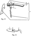
- the lever (2) is hinged on the head (13) in correspondence with a respective hinge (9), which allows a rotation of the lever (2) with respect to the handle (4) both for switchblade closure of the lever (2) itself in a proximity condition with the handle (4), and for allowing a reciprocal rotation between the lever (2) and the handle (4) during the extraction phase ( Fig. 8 , Fig. 9 , Fig. 10 , Fig. 11 , Fig. 12 , Fig. 13, Fig. 14 ) of a cork (21) from the neck of a bottle (22).
- the lever (2) has an elongated shape delimited by a first end (25) provided with propping teeth (10) and by a second end (26) in correspondence with which there is the hinge (9).
- the propping teeth (10) include a first tooth (11) and a second tooth (12).
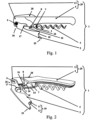
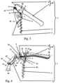
- the propping teeth (10) are located ( Fig. 1, Fig. 2 , Fig. 3, Fig. 4 , Fig. 5, Fig. 6 , Fig. 7 ) on the lever (2) in correspondence with the side of the lever (2) which faces the extraction screw (5).
- the lever (2) is shaped ( Fig. 2 , Fig. 4 ) with an essentially "U" shaped section, in which the end sides of the "U” shape form a first flank (19) and a second flank (20) which are essentially parallel, on each one of which a respective tooth of the propping teeth (10) is obtained.
- the first tooth (11) is obtained and on the second flank (20) the second tooth (12) is obtained, in such a way that the first tooth (11) and the second tooth (12) form a couple of reciprocally parallel propping teeth (10).
- the teeth (10, 11, 12) are used for engagement ( Fig. 8 , Fig. 9 , Fig. 10 , Fig. 11 , Fig. 12 , Fig. 13, Fig. 14 ) of the corkscrew (1) on the edge (23) of the neck of the bottle (22) during the extraction phases of the cork (21).
- the "U" shape of the lever (2) allows a reduction of the encumbrance when the corkscrew (1) must be put away, because the lever (2) can be thus folded on the body (29) receiving a portion of it within the hollow defined by the "U" shape.
- the corkscrew (1) can be without or can be provided with further accessory elements to be considered optional and irrelevant for the purposes of the present invention, such for example a blade (28), little knives or other cutting tools for example small wheels, of the type extractable from the handle (4), for the removal of the coating of the neck of the bottle according to known art.
- a blade 28
- little knives or other cutting tools for example small wheels
- the corkscrew (1) can be without or can be provided with further accessory elements to be considered optional and irrelevant for the purposes of the present invention, such as for example traditional opening hooks (17) for crown corks.
- the opening hooks (17) for crown corks which can also have the shape of an opening crotchet arranged on the lever (2) or on the handle (4).
- the extraction screw (5) is not directly fixed to the body (29) of the corkscrew (1) and is fixed to the body (29) of the corkscrew (1) with interposition of an extension element (3) according to a configuration in which:
- the extension element (3) is provided with a respective flattened terminal end of the extension element (3) in which this end is introduced within a corresponding insertion free space (18) obtained in the head (13) of the body (29), in such a way that this flattened terminal end is inserted in the free space (18) which guides the movement during the rotation around the first fulcrum point (8), obtained by means of a first pin passing through a couple of holes obtained in the head (13) and a hole obtained on the flattened terminal end of the extension element (3).
- the extraction screw (5) is provided with a terminal end of the screw with flattened section, in which this end is inserted within a corresponding insertion seat (14) obtained in the extension element (3), in such a way that this flattened terminal end is inserted in the seat (14) which guides its movement during the rotation around the second fulcrum point (7) obtained by means of a second pin passing through a couple of holes obtained in the extension element (3) and a hole obtained on the flattened terminal end of the extraction screw (5).
- the extraction screw (5) and the extension element (3) are reciprocally located in such a way that the axis of the screw (32) is parallel, preferably but not necessarily aligned, with respect to the axis (33) of the extension element, that is such that the axis of the screw (32) forms a first angle (A) with respect to the axis (33) of the extension element in which the first angle (A) has a first value which is equal to about 180°, possibly being able to have values included between 170° and 190°, without going beyond the scope of the present invention.
- the extraction occurs in the first sub-phase ( Fig. 3, Fig. 4 , Fig. 5 , Fig. 8 , Fig. 9, Fig. 10 ), for approximately the first half of the cork (21), according to one configuration and with force ratios similar to those of a corkscrew of traditional type with double lever.
- the first sub-phase occurs by exerting ( Fig. 9, Fig. 10 ) an opening force (27) on the handle (4) of the body (29).
- the extraction screw (5) and the lever (2) work in reciprocal synergy by means of rotation of the extraction screw (5) on the first fulcrum (8) and rotation of the lever (2) on the respective hinge (9), in which first fulcrum (8) and hinge (9) are spaced ( Fig.
- the axis of the extension element (33) is maintained parallel, preferably aligned, with respect to the axis of the screw (32), in such a way that the extension element (3) and the extraction screw (5) rotate together as a single body around the first fulcrum (8).
- the rotatory motion occurs involving a rotation of the assembly of extension element (3) and extraction screw (5) which rotate together with respect to the body (29) and also a reciprocal rotation between the body (29) and the lever (2) with respect to the hinge (9) with a progressive increase ( Fig. 8 , Fig.
- This blocking position of the first rotation phase is defined by the inclination of the second backing surface (24) present on the extension element (3) with respect to the axis of the extension element (33).
- the blocking position of the first rotation phase is defined in such a way that, in this position, the axis of the extension element (33) forms a second angle (B) of approximately 90° with respect to the axis of the body (30) of the corkscrew (1).
- the axis of the extension element (33) can form a second angle (B) with values included between 80° and 100° with respect to the axis of the body (30) of the corkscrew (1) without going beyond the scope of the present invention, also according to the form of the body (29).
- the lever ratio changes, thus having a multiplying effect of the lever most favourable for the extraction of the end part of the cork (21) also obtaining an acceleration of the extraction for the completion of the second part of the cork (21).
- the axis of the extension element (33) remains fixed with respect to the body (29) while the axis of the extraction screw (5), following the progressive rotation around the second fulcrum (7), is progressively inclined as the extraction proceeds, so that the first angle (A) changes formed between the axis of the screw (32) and the axis (33) of the extension element while simultaneously the value further increases of the angle included between the axis of the body (29), which is lifted, and the axis of the screw (32) which in this phase, in turn, tilts with respect to the axis of the extension element (33).
- the extraction of the cork (21) is obtained with a single uninterrupted extraction movement also having an additional further advantage which, as can be clearly seen in the figures ( Fig. 8 , Fig. 9 , Fig. 10 , Fig. 11 , Fig. 12 , Fig. 13, Fig. 14 ), relates to the fact that the extraction of the cork (21) from the neck of the bottle (22) occurs, especially in the second extraction sub-phase ( Fig. 11, Fig. 12 , Fig. 13, Fig. 14 ), perfectly vertically so that the axis of the cork is aligned with the axis of the extraction screw, in such a way as to avoid the breakage of the cork, besides allowing an easier uncorking.
- the second uncorking sub-phase develops inwards, that is with a progressive reduction of the first angle (A) formed between the axis of the screw (32) and the axis (33) of the extension element while simultaneously the value further increases of the angle included between the axis of the body (29), which is lifted, and the axis of the screw (32) which in this phase, in turn, tilts with respect to the axis of the extension element (33) taking a position in which the axis of the screw (32) remains parallel to the axis of the cork thanks to the rotation allowed by the second fulcrum (7).
- the present invention refers to a corkscrew (1) for extraction of a cork (21) from a neck of a bottle (22), comprising ( Fig. 1, Fig. 2 , Fig. 4 ):
- the corkscrew (1) further includes an extension element (3) constituting a fixing interface of the extraction screw (5) with respect to the first fulcrum (8) according to a configuration in which the extension element (3) is coupled to the body (29) in correspondence with the first fulcrum (8) and the extraction screw (5) is pivotably coupled to the extension element (3) by means of a second fulcrum (7), the assembly of extension element (3) and extraction screw (5) being provided with two fulcra (7, 8), that is first fulcrum (8) and second fulcrum (7), arranged one after the other.
- the first angle (A) has progressively lower values during the progress of the second extraction sub-phase of the cork for rotation of the extraction screw (5) with respect to the extension element (3) around the second fulcrum (7).
- a second angle (B) formed between the axis of the extension element (33) and an axis of longitudinal development of the body (30) of the corkscrew (1) is included between 15° and 100°.
- the second angle (B) maintains a fixed value in the absence of rotation of the extension element (3) with respect to the first fulcrum (8) and with rotation of the extraction screw (5) around the second fulcrum (7).
- the first backing surface (16) and the second backing surface (24) are in a condition of reciprocal contact with consequent blocking condition of the rotation of the pivotable coupling of the first fulcrum (8) between extraction screw (5) and body (29).
- the extraction method includes a blocking phase of the first sub-phase for the start of the second extraction sub-phase, in which the blocking phase occurs by means of interference between the previously described first backing surface (16) of the body (29) and second backing surface (24) of the extension element (3).
- the extraction phase composed of the two sub-phases consisting of first extraction sub-phase and second extraction sub-phase, occurs by means of lifting movement of the grasping handle (4), in which the lifting movement is continuous and without interruptions between the start of the extraction, the passage from first extraction sub-phase to second extraction sub-phase, end of the extraction.
Landscapes
- Engineering & Computer Science (AREA)
- Mechanical Engineering (AREA)
- Devices For Opening Bottles Or Cans (AREA)
Claims (17)
- Korkenzieher (1) zur Extraktion eines Korkens (21) aus einem Flaschenhals (22), der Folgendes umfasst:- einen Körper (29), der mit einem Haltegriff (4) und einem Endkopf (13) versehen ist, der von dem Griff (4) getragen wird;- einen Stützhebel (2), der mit mindestens einem Paar von Zähnen (10) zum Stützen auf einer Kante (23) des Flaschenhalses (22) versehen ist und bei dem der Hebel (2) ferner durch ein Scharnier (9) an dem Körper (29) in Übereinstimmung mit dem Kopf (13) angelenkt ist;- eine Extraktionsschraube (5) zur Extraktion des Korkens (21) durch Einsetzen durch Schrauben in das Volumen des Korkens (21), wobei die Schraube (5) eine spiralförmige Längserstreckung aufweist;- einen ersten Drehpunkt (8) zum schwenkbaren Koppeln der Extraktionsschraube (5) an den Körper (29) in Übereinstimmung mit dem Kopf (13), wobei der erste Drehpunkt (8) in einer Position des Kopfes (13) angeordnet ist, die in Bezug auf das Scharnier (9) beabstandet ist und zwischen dem Scharnier (9) und dem Griff (4) angeordnet ist;wobei der Korkenzieher (1) ferner ein Verlängerungselement (3) enthält, das eine Befestigungsschnittstelle der Extraktionsschraube (5) in Bezug auf den ersten Drehpunkt (8) gemäß einer Konfiguration bildet, in der das Verlängerungselement (3) mit dem Körper (29) in Übereinstimmung mit dem ersten Drehpunkt (8) gekoppelt ist und die Extraktionsschraube (5) mit dem Verlängerungselement (3) durch einen zweiten Drehpunkt (7) schwenkbar gekoppelt ist, wobei die Anordnung aus Verlängerungselement (3) und Extraktionsschraube (5) somit mit zwei Drehpunkten (7, 8) versehen ist, die aus einem ersten Drehpunkt (8) und einem zweiten Drehpunkt (7) bestehen, wobei der Korkenzieher (1) zwischen zwei Extraktionskonfigurationen des Korkens (21) konfigurierbar ist, die unterschiedliche Winkelwerte eines ersten Winkels (A) aufweisen, der der Winkel ist, der zwischen einer Achse des Verlängerungselements (33), das den ersten Drehpunkt (8) und den zweiten Drehpunkt (7) verbindet, und einer Achse der Schraube (32) gebildet ist, die die Achse der spiralförmigen Längserstreckung der Schraube (5) ist, wobei:- eine erste Extraktionskonfiguration für eine entsprechende erste Extraktionsteilphase des Korkens einen Wert des ersten Winkels (A) zwischen 170° und 190°, vorzugsweise gleich etwa 180° aufweist;- eine zweite Extraktionskonfiguration für eine entsprechende zweite Extraktionsteilphase des Korkens Werte des ersten Winkels (A) aufweist, die niedriger als der Wert des ersten Winkels (A) der ersten Extraktionskonfiguration sind,gekennzeichnet dadurch, dass in der ersten Extraktionskonfiguration während der entsprechenden ersten Extraktionsteilphase des Korkens der erste Winkel (A) einen festen Wert für die Drehung der Anordnung aus Verlängerungselement (3) und Extraktionsschraube (5) um den ersten Drehpunkt (8) aufweist, wobei eine Betätigungskraft auf den Griff einer Zugkraft auf die Extraktionsschraube (5) gemäß einer mit dem Verlängerungselement (3) ausgerichteten Richtung entspricht, wobei eine erste Stützfläche (16) auf dem Körper (29) des Korkenziehers vorhanden ist, wobei die erste Stützfläche (16) nahe dem ersten Drehpunkt (8) angeordnet ist, wobei eine zweite Stützfläche (24) auf dem Verlängerungselement (3) vorhanden ist, die gemäß einer Konfiguration angeordnet ist, in der ein Zustand des gegenseitigen Kontakts zwischen der ersten Stützfläche (16) und der zweiten Stützfläche (24) einen Blockierungszustand der schwenkbaren Kopplung des ersten Drehpunkts (8) zwischen der Extraktionsschraube (5) und dem Körper (29) für den automatischen Übergang von der ersten Extraktionskonfiguration zu der zweiten Extraktionskonfiguration für eine kontinuierliche Extraktionsbewegung des Korkens (21) darstellt.
- Korkenzieher (1) nach dem vorhergehenden Anspruch, gekennzeichnet dadurch, dass die zweite Extraktionskonfiguration durch Werte des ersten Winkels (A) zwischen 80° und 170° gekennzeichnet ist, wobei mit Ausnahme von 170° die Werte der zweiten Extraktionskonfiguration in Bezug auf den ersten Wert des ersten Winkels (A) in der ersten Konfiguration niedriger sind.
- Korkenzieher (1) nach einem der vorhergehenden Ansprüche, gekennzeichnet dadurch, dass in der zweiten Extraktionskonfiguration während der entsprechenden zweiten Extraktionsteilphase des Korkens der erste Winkel (A) während des Verlaufs der zweiten Extraktionsteilphase des Korkens für die Drehung der Extraktionsschraube (5) in Bezug auf das Verlängerungselement (3) um den zweiten Drehpunkt (7) zunehmend niedrigere Werte aufweist.
- Korkenzieher (1) nach einem der vorhergehenden Ansprüche, gekennzeichnet dadurch, dass in der ersten Extraktionskonfiguration während der entsprechenden ersten Extraktionsteilphase des Korkens ein zweiter Winkel (B), der zwischen der Achse des Verlängerungselements (33) und einer Längsentwicklungsachse des Körpers (30) des Korkenziehers (1) gebildet ist, zwischen 15° und 100° liegt.
- Korkenzieher (1) nach dem vorhergehenden Anspruch, gekennzeichnet dadurch, dass in der zweiten Extraktionskonfiguration während der entsprechenden zweiten Extraktionsteilphase des Korkens der zweite Winkel (B) zwischen 80° und 100° liegt.
- Korkenzieher (1) nach einem der vorhergehenden Ansprüche 4 bis 5, gekennzeichnet dadurch, dass
in der ersten Extraktionskonfiguration während der entsprechenden ersten Extraktionsteilphase des Korkens der zweite Winkel (B) während des Verlaufs der ersten Extraktionsteilphase des Korkens für die Drehung des Verlängerungselements (3) in Bezug auf den Körper (29) des Korkenziehers (1) um den ersten Drehpunkt (8) zunehmend niedrigere Werte aufweist. - Korkenzieher (1) nach einem der vorhergehenden Ansprüche 4 bis 6, gekennzeichnet dadurch, dass
in der zweiten Extraktionskonfiguration während der entsprechenden zweiten Extraktionsteilphase des Korkens der zweite Winkel (B) einen festen Wert aufweist, wenn keine Drehung des Verlängerungselements (3) in Bezug auf den ersten Drehpunkt (8) erfolgt und eine Drehung der Extraktionsschraube (5) um den zweiten Drehpunkt (7) erfolgt. - Korkenzieher (1) nach einem der vorhergehenden Ansprüche, gekennzeichnet dadurch, dass in der ersten Extraktionskonfiguration für die entsprechende erste Extraktionsteilphase des Korkens die erste Stützfläche (16) und die zweite Stützfläche (24) sich nicht in einem Zustand des gegenseitigen Kontakts befinden, was zu einem Zustand der freien Drehung der schwenkbaren Kopplung des ersten Drehpunkts (8) zwischen der Extraktionsschraube (5) und dem Körper (29) führt.
- Korkenzieher (1) nach einem der vorhergehenden Ansprüche, gekennzeichnet dadurch, dass in der zweiten Extraktionskonfiguration für die entsprechende zweite Extraktionsteilphase des Korkens die erste Stützfläche (16) und die zweite Stützfläche (24) sich in einem Zustand des gegenseitigen Kontakts mit daraus folgendem Blockierungszustand der Drehung der schwenkbaren Kopplung des ersten Drehpunkts (8) zwischen der Extraktionsschraube (5) und dem Körper (29) befinden.
- Extraktionsverfahren eines Korkens (21) aus einem Flaschenhals (22) durch einen Extraktionskorkenzieher (1) nach Anspruch 1, wobei das Verfahren eine Schraubphase der Extraktionsschraube (5) in den Korken (21) zum Einführen der Schraube (5) in das Volumen des Korkens (21) und eine Auflagephase des Stützhebels (2) auf der Kante (23) des Flaschenhalses (22) durch Auflagern des mindestens einen Paars von Zähnen (10) auf der Kante (23) des Flaschenhalses (22) umfasst, wobei das Verfahren ferner eine Extraktionsphase umfasst, die in zwei Teilphasen unterteilt ist, von denen:- eine erste Extraktionsteilphase der besagten ersten Extraktionskonfiguration entspricht, in der die Extraktion durch eine Drehphase einer Anordnung erfolgt, die aus der Extraktionsschraube (5) und dem Verlängerungselement (3) besteht, das eine Befestigungsschnittstelle der Extraktionsschraube (5) in Bezug auf den ersten Drehpunkt (8) bildet, gemäß einer Konfiguration, in der das Verlängerungselement (3) mit dem Körper (29) in Übereinstimmung mit dem ersten Drehpunkt (8) gekoppelt ist und die Extraktionsschraube (5) schwenkbar mit dem Verlängerungselement (3) durch den zweiten Drehpunkt (7) gekoppelt ist, wobei die Anordnung aus Verlängerungselement (3) und Extraktionsschraube (5) somit mit zwei Drehpunkten (7, 8) versehen ist, d.h. einem ersten Drehpunkt (8) und einem zweiten Drehpunkt (7), die hintereinander angeordnet sind, wobei die erste Extraktionsteilphase durch Drehung der Anordnung aus Extraktionsschraube (5) und Verlängerungselement (3) um den ersten Drehpunkt (8) erfolgt, wenn keine Drehung der Extraktionsschraube (5) um den zweiten Drehpunkt (7) erfolgt;- eine zweite Extraktionsteilphase der besagten zweiten Extraktionskonfiguration entspricht, in der die Extraktion durch eine Drehphase der Extraktionsschraube (5) um den zweiten Drehpunkt (7) erfolgt, wenn keine Drehung des Verlängerungselements (3) um den ersten Drehpunkt (8) erfolgt;wobei die Extraktionsphase durch eine Hebebewegung des Haltegriffs (4) erfolgt und die besagten zwei Teilphasen umfasst, die aus der ersten Extraktionsteilphase und der zweiten Extraktionsteilphase bestehen, wobei während der entsprechenden ersten Extraktionsteilphase des Korkens der erste Winkel (A) den besagten festen Wert für die Drehung der Anordnung aus Verlängerungselement (3) und Extraktionsschraube (5) um den ersten Drehpunkt (8) zur Ausführung einer Hebebewegung aufweist, die kontinuierlich und ohne Unterbrechungen zwischen dem Beginn der Extraktion, dem Übergang von der ersten Extraktionsteilphase zu der zweiten Extraktionsteilphase und dem Ende der Extraktion ist, wobei das Verfahren eine Blockierungsphase der ersten Extraktionsteilphase für den Beginn der zweiten Extraktionsteilphase enthält, wobei die Blockierungsphase durch Interferenz zwischen Folgenden erfolgt:- der ersten Stützfläche (16) des Körpers (29), wobei die erste Stützfläche (16) nahe dem ersten Drehpunkt (8) angeordnet ist;- der zweiten Stützfläche (24) des Verlängerungselements (3);wobei die erste Stützfläche (16) und die zweite Stützfläche (24) gemäß einer Konfiguration angeordnet sind, in der nach der Drehung der Anordnung, die aus Extraktionsschraube (5) und Verlängerungselement (3) besteht, ein Zustand des gegenseitigen Kontakts zwischen der ersten Stützfläche (16) und der zweiten Stützfläche (24) auftritt, der der besagten Blockierungsphase entspricht, was einen Blockierungszustand der schwenkbaren Kopplung des ersten Drehpunkts (8) zwischen der Extraktionsschraube (5) und dem Körper (29) für den Beginn der zweiten Extraktionsteilphase bewirkt.
- Extraktionsverfahren eines Korkens (21) nach dem vorhergehenden Anspruch, gekennzeichnet dadurch, dass
die zweite Extraktionsteilphase durch Werte des ersten Winkels (A) zwischen 80° und 170° gekennzeichnet ist, wobei mit Ausnahme von 170° die Werte der zweiten Extraktionskonfiguration in Bezug auf den ersten Wert des ersten Winkels (A) in der ersten Konfiguration niedriger sind. - Extraktionsverfahren eines Korkens (21) nach einem der vorhergehenden Ansprüche 10 bis 11, gekennzeichnet dadurch, dass
während der ersten Extraktionsteilphase des Korkens der erste Winkel (A) einen festen Wert mit entsprechender Drehungsphase der Anordnung aus Verlängerungselement (3) und Extraktionsschraube (5) um den ersten Drehpunkt (8) beibehält. - Extraktionsverfahren eines Korkens (21) nach einem der vorhergehenden Ansprüche 10 bis 12, gekennzeichnet dadurch, dass
während der zweiten Extraktionsteilphase des Korkens der erste Winkel (A) während des Verlaufs der zweiten Extraktionsteilphase des Korkens mit entsprechender Drehphase der Extraktionsschraube (5) in Bezug auf das Verlängerungselement (3) um den zweiten Drehpunkt (7) zunehmend niedrigere Werte aufweist. - Extraktionsverfahren eines Korkens (21) nach einem der vorhergehenden Ansprüche 10 bis 13, gekennzeichnet dadurch, dass
während der ersten Extraktionsteilphase des Korkens ein zweiter Winkel (B), der zwischen der Achse des Verlängerungselements (33) und einer Längsentwicklungsachse des Körpers (30) des Korkenziehers (1) gebildet ist, zwischen 15° und 100° liegt. - Extraktionsverfahren eines Korkens (21) nach dem vorhergehenden Anspruch, gekennzeichnet dadurch, dass
während der zweiten Extraktionsteilphase des Korkens der zweite Winkel (B) zwischen 80° und 100° liegt. - Extraktionsverfahren eines Korkens (21) nach einem der vorhergehenden Ansprüche 14 bis 15, gekennzeichnet dadurch, dass
während der ersten Extraktionsteilphase des Korkens der zweite Winkel (B) während des Verlaufs der ersten Extraktionsteilphase des Korkens für die Drehung des Verlängerungselements (3) in Bezug auf den Körper (29) des Korkenziehers (1) um den ersten Drehpunkt (8) zunehmend niedrigere Werte aufweist. - Extraktionsverfahren eines Korkens (21) nach einem der vorhergehenden Ansprüche 14 bis 16, gekennzeichnet dadurch, dass
während der zweiten Extraktionsteilphase des Korkens der zweite Winkel (B) einen festen Wert beibehält, wenn keine Drehung des Verlängerungselements (3) in Bezug auf den ersten Drehpunkt (8) erfolgt und eine Drehung der Extraktionsschraube (5) um den zweiten Drehpunkt (7) erfolgt.
Applications Claiming Priority (2)
| Application Number | Priority Date | Filing Date | Title |
|---|---|---|---|
| IT102019000020090A IT201900020090A1 (it) | 2019-10-30 | 2019-10-30 | Cavatappi con leva di puntellamento e metodo di estrazione di un tappo |
| PCT/EP2020/000184 WO2021083540A1 (en) | 2019-10-30 | 2020-10-29 | Corkscrew with propping lever and method for the extraction of a cork |
Publications (3)
| Publication Number | Publication Date |
|---|---|
| EP4051623A1 EP4051623A1 (de) | 2022-09-07 |
| EP4051623B1 true EP4051623B1 (de) | 2023-12-20 |
| EP4051623C0 EP4051623C0 (de) | 2023-12-20 |
Family
ID=69903753
Family Applications (1)
| Application Number | Title | Priority Date | Filing Date |
|---|---|---|---|
| EP20811236.7A Active EP4051623B1 (de) | 2019-10-30 | 2020-10-29 | Korkenzieher mit stützhebel und verfahren zur extraktion eines korkens |
Country Status (4)
| Country | Link |
|---|---|
| US (1) | US12030765B2 (de) |
| EP (1) | EP4051623B1 (de) |
| IT (1) | IT201900020090A1 (de) |
| WO (1) | WO2021083540A1 (de) |
Family Cites Families (6)
| Publication number | Priority date | Publication date | Assignee | Title |
|---|---|---|---|---|
| ES1020637Y (es) | 1992-03-24 | 1993-03-01 | Brucart Puig Ramon | Sacacorchos de doble apoyo. |
| US7614323B2 (en) * | 2001-11-29 | 2009-11-10 | Warner Brent J | Corkscrew for one handed operation |
| ITUD20040004A1 (it) | 2004-01-15 | 2004-04-15 | Daniele Farfalli | Cavatappi a doppia leva di puntellamento |
| US7377196B1 (en) * | 2007-03-06 | 2008-05-27 | Hsing-Hui Chen | Corkscrew having an angle adjustable function |
| ES2590402B1 (es) * | 2015-04-21 | 2017-04-24 | Koala Internacional Hosteleria, S.L. | Sacacorchos |
| EP3459905B1 (de) * | 2017-09-26 | 2022-01-05 | Sknife AG | Kellnermesser |
-
2019
- 2019-10-30 IT IT102019000020090A patent/IT201900020090A1/it unknown
-
2020
- 2020-10-29 US US17/772,744 patent/US12030765B2/en active Active
- 2020-10-29 EP EP20811236.7A patent/EP4051623B1/de active Active
- 2020-10-29 WO PCT/EP2020/000184 patent/WO2021083540A1/en not_active Ceased
Also Published As
| Publication number | Publication date |
|---|---|
| US12030765B2 (en) | 2024-07-09 |
| US20220388827A1 (en) | 2022-12-08 |
| EP4051623A1 (de) | 2022-09-07 |
| WO2021083540A1 (en) | 2021-05-06 |
| IT201900020090A1 (it) | 2021-04-30 |
| EP4051623C0 (de) | 2023-12-20 |
Similar Documents
| Publication | Publication Date | Title |
|---|---|---|
| US4584911A (en) | Corkscrew device | |
| US6116116A (en) | Corkscrew with ribbed arm | |
| EP1708954B1 (de) | Korkenzieher mit doppeltem stützhebel | |
| US20120222280A1 (en) | Level Corkscrew Having a Double Fulcrum and Method of Using Same | |
| US20110185859A1 (en) | Corkscrew | |
| US20090301261A1 (en) | Snap-type corkscrew | |
| US20020157188A1 (en) | Waiter's friend corkscrew | |
| KR200462449Y1 (ko) | 캔 오픈장치 | |
| US12030765B2 (en) | Corkscrew with propping lever and method for the extraction of a cork | |
| US12503350B2 (en) | Apparatus and method for removing an internal closure from a container | |
| EP2593395B1 (de) | Doppelhebelkorkenzieher | |
| EP3621914B1 (de) | Korkenzieher | |
| US4750391A (en) | Opener for removing champagne-type corks | |
| AU2004315115A1 (en) | Corkscrew | |
| US6530295B1 (en) | Corkscrew spacer | |
| EP0064644A1 (de) | Führungs- und Positioniermechanismus für die Bohrstange des Abstichloches am Schachtofen und Stichlochbohrmaschine mit einem solchen Mechanismus | |
| US9670043B2 (en) | Lever corkscrew with removable wrapper cutter | |
| KR101886004B1 (ko) | 음료수 캔의 원형 고리 따개 | |
| EP0291546B1 (de) | Sektflaschen-Entkorker | |
| US1861993A (en) | Cork extractor and bottle opener | |
| CN214399748U (zh) | 用于输液瓶的启瓶器 | |
| WO2003084858A1 (en) | Pocket corkscrew | |
| LU83335A1 (fr) | Dispositif de centrage et de guidage d'une tige de percage du trou de coulee d'un four a cuve et perceuse pourvue d'un tel dispositif | |
| ES2898060T3 (es) | Sacacorchos y procedimiento asociado para la extracción de un corcho | |
| WO2005056463A2 (en) | Cork extractor apparatus and method |
Legal Events
| Date | Code | Title | Description |
|---|---|---|---|
| STAA | Information on the status of an ep patent application or granted ep patent |
Free format text: STATUS: UNKNOWN |
|
| STAA | Information on the status of an ep patent application or granted ep patent |
Free format text: STATUS: THE INTERNATIONAL PUBLICATION HAS BEEN MADE |
|
| PUAI | Public reference made under article 153(3) epc to a published international application that has entered the european phase |
Free format text: ORIGINAL CODE: 0009012 |
|
| STAA | Information on the status of an ep patent application or granted ep patent |
Free format text: STATUS: REQUEST FOR EXAMINATION WAS MADE |
|
| 17P | Request for examination filed |
Effective date: 20220524 |
|
| AK | Designated contracting states |
Kind code of ref document: A1 Designated state(s): AL AT BE BG CH CY CZ DE DK EE ES FI FR GB GR HR HU IE IS IT LI LT LU LV MC MK MT NL NO PL PT RO RS SE SI SK SM TR |
|
| DAV | Request for validation of the european patent (deleted) | ||
| DAX | Request for extension of the european patent (deleted) | ||
| GRAP | Despatch of communication of intention to grant a patent |
Free format text: ORIGINAL CODE: EPIDOSNIGR1 |
|
| STAA | Information on the status of an ep patent application or granted ep patent |
Free format text: STATUS: GRANT OF PATENT IS INTENDED |
|
| INTG | Intention to grant announced |
Effective date: 20230711 |
|
| GRAS | Grant fee paid |
Free format text: ORIGINAL CODE: EPIDOSNIGR3 |
|
| GRAA | (expected) grant |
Free format text: ORIGINAL CODE: 0009210 |
|
| STAA | Information on the status of an ep patent application or granted ep patent |
Free format text: STATUS: THE PATENT HAS BEEN GRANTED |
|
| AK | Designated contracting states |
Kind code of ref document: B1 Designated state(s): AL AT BE BG CH CY CZ DE DK EE ES FI FR GB GR HR HU IE IS IT LI LT LU LV MC MK MT NL NO PL PT RO RS SE SI SK SM TR |
|
| RAP3 | Party data changed (applicant data changed or rights of an application transferred) |
Owner name: FARFALLI, DANIELE |
|
| REG | Reference to a national code |
Ref country code: GB Ref legal event code: FG4D |
|
| RIN1 | Information on inventor provided before grant (corrected) |
Inventor name: FARFALLI, DANIELE |
|
| REG | Reference to a national code |
Ref country code: CH Ref legal event code: EP |
|
| REG | Reference to a national code |
Ref country code: DE Ref legal event code: R096 Ref document number: 602020023162 Country of ref document: DE |
|
| REG | Reference to a national code |
Ref country code: IE Ref legal event code: FG4D |
|
| U01 | Request for unitary effect filed |
Effective date: 20240115 |
|
| U07 | Unitary effect registered |
Designated state(s): AT BE BG DE DK EE FI FR IT LT LU LV MT NL PT SE SI Effective date: 20240126 |
|
| PG25 | Lapsed in a contracting state [announced via postgrant information from national office to epo] |
Ref country code: GR Free format text: LAPSE BECAUSE OF FAILURE TO SUBMIT A TRANSLATION OF THE DESCRIPTION OR TO PAY THE FEE WITHIN THE PRESCRIBED TIME-LIMIT Effective date: 20240321 |
|
| PG25 | Lapsed in a contracting state [announced via postgrant information from national office to epo] |
Ref country code: ES Free format text: LAPSE BECAUSE OF FAILURE TO SUBMIT A TRANSLATION OF THE DESCRIPTION OR TO PAY THE FEE WITHIN THE PRESCRIBED TIME-LIMIT Effective date: 20231220 |
|
| PG25 | Lapsed in a contracting state [announced via postgrant information from national office to epo] |
Ref country code: GR Free format text: LAPSE BECAUSE OF FAILURE TO SUBMIT A TRANSLATION OF THE DESCRIPTION OR TO PAY THE FEE WITHIN THE PRESCRIBED TIME-LIMIT Effective date: 20240321 Ref country code: ES Free format text: LAPSE BECAUSE OF FAILURE TO SUBMIT A TRANSLATION OF THE DESCRIPTION OR TO PAY THE FEE WITHIN THE PRESCRIBED TIME-LIMIT Effective date: 20231220 |
|
| PG25 | Lapsed in a contracting state [announced via postgrant information from national office to epo] |
Ref country code: RS Free format text: LAPSE BECAUSE OF FAILURE TO SUBMIT A TRANSLATION OF THE DESCRIPTION OR TO PAY THE FEE WITHIN THE PRESCRIBED TIME-LIMIT Effective date: 20231220 Ref country code: NO Free format text: LAPSE BECAUSE OF FAILURE TO SUBMIT A TRANSLATION OF THE DESCRIPTION OR TO PAY THE FEE WITHIN THE PRESCRIBED TIME-LIMIT Effective date: 20240320 Ref country code: HR Free format text: LAPSE BECAUSE OF FAILURE TO SUBMIT A TRANSLATION OF THE DESCRIPTION OR TO PAY THE FEE WITHIN THE PRESCRIBED TIME-LIMIT Effective date: 20231220 |
|
| PG25 | Lapsed in a contracting state [announced via postgrant information from national office to epo] |
Ref country code: IS Free format text: LAPSE BECAUSE OF FAILURE TO SUBMIT A TRANSLATION OF THE DESCRIPTION OR TO PAY THE FEE WITHIN THE PRESCRIBED TIME-LIMIT Effective date: 20240420 |
|
| PG25 | Lapsed in a contracting state [announced via postgrant information from national office to epo] |
Ref country code: CZ Free format text: LAPSE BECAUSE OF FAILURE TO SUBMIT A TRANSLATION OF THE DESCRIPTION OR TO PAY THE FEE WITHIN THE PRESCRIBED TIME-LIMIT Effective date: 20231220 |
|
| PG25 | Lapsed in a contracting state [announced via postgrant information from national office to epo] |
Ref country code: SK Free format text: LAPSE BECAUSE OF FAILURE TO SUBMIT A TRANSLATION OF THE DESCRIPTION OR TO PAY THE FEE WITHIN THE PRESCRIBED TIME-LIMIT Effective date: 20231220 |
|
| PG25 | Lapsed in a contracting state [announced via postgrant information from national office to epo] |
Ref country code: SM Free format text: LAPSE BECAUSE OF FAILURE TO SUBMIT A TRANSLATION OF THE DESCRIPTION OR TO PAY THE FEE WITHIN THE PRESCRIBED TIME-LIMIT Effective date: 20231220 Ref country code: SK Free format text: LAPSE BECAUSE OF FAILURE TO SUBMIT A TRANSLATION OF THE DESCRIPTION OR TO PAY THE FEE WITHIN THE PRESCRIBED TIME-LIMIT Effective date: 20231220 Ref country code: RO Free format text: LAPSE BECAUSE OF FAILURE TO SUBMIT A TRANSLATION OF THE DESCRIPTION OR TO PAY THE FEE WITHIN THE PRESCRIBED TIME-LIMIT Effective date: 20231220 Ref country code: IS Free format text: LAPSE BECAUSE OF FAILURE TO SUBMIT A TRANSLATION OF THE DESCRIPTION OR TO PAY THE FEE WITHIN THE PRESCRIBED TIME-LIMIT Effective date: 20240420 Ref country code: CZ Free format text: LAPSE BECAUSE OF FAILURE TO SUBMIT A TRANSLATION OF THE DESCRIPTION OR TO PAY THE FEE WITHIN THE PRESCRIBED TIME-LIMIT Effective date: 20231220 |
|
| PG25 | Lapsed in a contracting state [announced via postgrant information from national office to epo] |
Ref country code: PL Free format text: LAPSE BECAUSE OF FAILURE TO SUBMIT A TRANSLATION OF THE DESCRIPTION OR TO PAY THE FEE WITHIN THE PRESCRIBED TIME-LIMIT Effective date: 20231220 |
|
| PG25 | Lapsed in a contracting state [announced via postgrant information from national office to epo] |
Ref country code: PL Free format text: LAPSE BECAUSE OF FAILURE TO SUBMIT A TRANSLATION OF THE DESCRIPTION OR TO PAY THE FEE WITHIN THE PRESCRIBED TIME-LIMIT Effective date: 20231220 |
|
| REG | Reference to a national code |
Ref country code: DE Ref legal event code: R097 Ref document number: 602020023162 Country of ref document: DE |
|
| PLBE | No opposition filed within time limit |
Free format text: ORIGINAL CODE: 0009261 |
|
| STAA | Information on the status of an ep patent application or granted ep patent |
Free format text: STATUS: NO OPPOSITION FILED WITHIN TIME LIMIT |
|
| 26N | No opposition filed |
Effective date: 20240923 |
|
| U20 | Renewal fee for the european patent with unitary effect paid |
Year of fee payment: 5 Effective date: 20241031 |
|
| PG25 | Lapsed in a contracting state [announced via postgrant information from national office to epo] |
Ref country code: MC Free format text: LAPSE BECAUSE OF FAILURE TO SUBMIT A TRANSLATION OF THE DESCRIPTION OR TO PAY THE FEE WITHIN THE PRESCRIBED TIME-LIMIT Effective date: 20231220 |
|
| PG25 | Lapsed in a contracting state [announced via postgrant information from national office to epo] |
Ref country code: IE Free format text: LAPSE BECAUSE OF NON-PAYMENT OF DUE FEES Effective date: 20241029 |
|
| REG | Reference to a national code |
Ref country code: CH Ref legal event code: U11 Free format text: ST27 STATUS EVENT CODE: U-0-0-U10-U11 (AS PROVIDED BY THE NATIONAL OFFICE) Effective date: 20251101 |
|
| U20 | Renewal fee for the european patent with unitary effect paid |
Year of fee payment: 6 Effective date: 20251031 |
|
| PGFP | Annual fee paid to national office [announced via postgrant information from national office to epo] |
Ref country code: GB Payment date: 20251021 Year of fee payment: 6 |
|
| PGFP | Annual fee paid to national office [announced via postgrant information from national office to epo] |
Ref country code: CH Payment date: 20251101 Year of fee payment: 6 |
|
| PG25 | Lapsed in a contracting state [announced via postgrant information from national office to epo] |
Ref country code: HU Free format text: LAPSE BECAUSE OF FAILURE TO SUBMIT A TRANSLATION OF THE DESCRIPTION OR TO PAY THE FEE WITHIN THE PRESCRIBED TIME-LIMIT; INVALID AB INITIO Effective date: 20201029 |
|
| PG25 | Lapsed in a contracting state [announced via postgrant information from national office to epo] |
Ref country code: CY Free format text: LAPSE BECAUSE OF FAILURE TO SUBMIT A TRANSLATION OF THE DESCRIPTION OR TO PAY THE FEE WITHIN THE PRESCRIBED TIME-LIMIT; INVALID AB INITIO Effective date: 20201029 |
|
| PG25 | Lapsed in a contracting state [announced via postgrant information from national office to epo] |
Ref country code: TR Free format text: LAPSE BECAUSE OF FAILURE TO SUBMIT A TRANSLATION OF THE DESCRIPTION OR TO PAY THE FEE WITHIN THE PRESCRIBED TIME-LIMIT Effective date: 20231220 |